EP2897142A1 - Induktiver Spannungswandler - Google Patents
Induktiver Spannungswandler Download PDFInfo
- Publication number
- EP2897142A1 EP2897142A1 EP14195814.0A EP14195814A EP2897142A1 EP 2897142 A1 EP2897142 A1 EP 2897142A1 EP 14195814 A EP14195814 A EP 14195814A EP 2897142 A1 EP2897142 A1 EP 2897142A1
- Authority
- EP
- European Patent Office
- Prior art keywords
- primary coil
- coil
- voltage converter
- voltage
- layers
- Prior art date
- Legal status (The legal status is an assumption and is not a legal conclusion. Google has not performed a legal analysis and makes no representation as to the accuracy of the status listed.)
- Granted
Links
Images


Classifications
-
- H—ELECTRICITY
- H01—ELECTRIC ELEMENTS
- H01F—MAGNETS; INDUCTANCES; TRANSFORMERS; SELECTION OF MATERIALS FOR THEIR MAGNETIC PROPERTIES
- H01F27/00—Details of transformers or inductances, in general
- H01F27/34—Special means for preventing or reducing unwanted electric or magnetic effects, e.g. no-load losses, reactive currents, harmonics, oscillations, leakage fields
-
- H—ELECTRICITY
- H01—ELECTRIC ELEMENTS
- H01F—MAGNETS; INDUCTANCES; TRANSFORMERS; SELECTION OF MATERIALS FOR THEIR MAGNETIC PROPERTIES
- H01F27/00—Details of transformers or inductances, in general
- H01F27/02—Casings
- H01F27/022—Encapsulation
-
- H—ELECTRICITY
- H01—ELECTRIC ELEMENTS
- H01F—MAGNETS; INDUCTANCES; TRANSFORMERS; SELECTION OF MATERIALS FOR THEIR MAGNETIC PROPERTIES
- H01F27/00—Details of transformers or inductances, in general
- H01F27/40—Structural association with built-in electric component, e.g. fuse
Definitions
- the invention relates to inductive voltage transformers and in particular low and medium voltage converters.
- harmonics In the electrical energy supply networks, in particular in low and medium voltage networks (up to 1 kV or between 1 kV and 75 kV) occur more harmonics. These harmonics are mainly caused by regenerative generation plants and customers with frequency converters and adversely affect the so-called "power quality" or the voltage quality of a power supply network. In order to ensure a desired voltage quality in a power supply network, it is first necessary to determine the actually existing voltage quality.
- Harmonics can be quantified by a THD (total harmonic distortion) value.
- the harmonic content or the THD value must be below 0.08 for an acceptable voltage quality in accordance with the applicable VDE and IEC regulations in low and medium voltage networks in the frequency range up to 2.5 kHz. In addition, it is recommended that the THD value in the frequency range between 2.5 kHz and 9 kHz does not exceed the limit of 0.002. Individual values also apply to the individual harmonics, which must be complied with. In order to check compliance with these limits, voltage converters with downstream measuring devices should preferably be used.
- the low and medium voltage from the power grid should be reduced so that designed for low voltages and therefore cost-effective measuring devices can be used to measure voltage or voltage waveforms in a low or medium voltage network. From the results of the measuring devices, which are arranged behind a voltage transformer, conclusions can be drawn on the conditions in the respective low- or medium-voltage network, in particular also with regard to the voltage quality.
- inductive voltage transformers are known as voltage transformers. These work on the principle of the transformer.
- corresponding voltage transformers basically have natural oscillations that are relevant for the harmonics in low and medium voltage networks Frequency range, which disturb the transmission in the voltage converter.
- a 20 kV inductive voltage converter according to the prior art have natural oscillations in the frequency range of 2 kHz to 15 kHz, the transmission ratio of the voltage converter from 1.5 kHz can be so strongly influenced that a measurement of the harmonics using a corresponding voltage converter is not possible.
- there is a limitation of the frequency band whereby only frequencies below 1.5 kHz can be transmitted acceptable.
- a determination of harmonics in a low or medium voltage network over 1.5 kHz is therefore not or only partially possible with an inductive voltage converter according to the prior art. The same applies to the verification of THD values in low and medium voltage networks.
- the capacitors with corresponding voltage transformers must withstand a high voltage and are consequently exposed to a certain aging, in which the capacitance of the capacitor can change. By changing the capacitance, however, the natural vibration behavior of the combination of voltage converter and capacitor changes, so that a preferred for the review of the voltage quality constant transmission behavior can not be guaranteed.
- the invention has for its object to provide a low-maintenance voltage converter, which is adapted to transmit the harmonics in low or medium voltage networks such that the harmonics with a downstream measuring device for determining the voltage quality in the low or medium voltage network sufficiently accurate during the entire life of the transducer can be detected.
- the invention relates to voltage converter comprising a primary coil, at least one secondary coil and a coil core, wherein the at least one secondary coil to the Spool core and the primary coil is arranged around the at least one secondary coil, wherein a capacitance is provided parallel to the layers of the primary coil, wherein the capacitance is connected in parallel to the lowermost layers of the primary coil, wherein the number of lowermost layers is less than half of Number of all layers of the primary coil.
- lowest layers of the primary coil are those winding or winding layers of the primary coil, which are located on the inside and thus closest to the coil core.
- the term “lowest layers of the primary coil” also includes the lowest layer of the primary coil.
- a primary coil of a voltage transformer for low and medium voltages typically has at least 2, at least 10 or at least 20 layers.
- the invention is based on the finding that despite the smaller number of layers compared to the prior art, to which the capacitance is connected in parallel, the inventive arrangement of the capacitance has a nearly linear transmission behavior in a wide frequency range starting from and greater than 0 Hz can be achieved, which is advantageous for use as a measuring voltage converter for low and medium voltage networks and brings the desired improvement over a wider frequency range.
- the capacity is not connected in parallel to half the layers of the primary coil, but to a smaller number of layers, it is basically sufficient if the capacitance has a lower dielectric strength. As a result, less expensive capacitors or capacitors can be used.
- the capacitance in the solution according to the invention is also generally loaded with less voltage than the prior art, more cost-effective capacitors can be used. Also, possibly aging effects are lower.
- the capacitance may be connected in parallel to the lowest 10% of the layers of the primary coil, preferably to the lowest 5% of the layers of the primary coil, more preferably to the bottom 3% of the layers of the primary coil. It is also possible for the capacitance to be connected in parallel only to the lowermost or the two lowest layers of the primary coil.
- the capacity is in each case to be selected such that the desired pole-zero compensation is achieved at the first resonance.
- the capacity suitable for the desired pole-zero compensation can be determined, for example, by tests.
- the capacitance For parallel connection with the lowest layers of the primary coil, the capacitance with its one connection with the Lead to the lowest position of the primary coil to be connected.
- the other terminal of the capacitance is further connected to the primary coil itself in order to achieve the parallel connection according to the invention.
- Voltage transformers for low and medium voltages are usually cast resin insulated, d. h., The individual components of the voltage converter are completely enclosed by the casting resin.
- the casting resin fills the space around the coils and thus acts as a different dielectric from air, which also changes the frequency response of the voltage converter.
- the casting resin insulation of the prior art comprises the primary coil, the at least one secondary coil, the coil core and the capacitor connected in parallel.
- the voltage converter according to the invention preferably also has a cast resin insulation, but the capacitance is arranged outside of the cast resin insulation.
- the cast resin insulation thus encloses the primary coil, the at least one secondary coil and the coil core, but not the capacitance, which is connected in parallel with the lowermost layers of the primary coil.
- the arrangement of the capacitance outside the cast resin insulation can be achieved, for example, by means of connecting lines that extend through the cast resin insulation.
- the arrangement of the capacitance outside of the cast resin insulation offers several advantages. So can on an elaborate upholstery
- the capacity is made interchangeable. This allows a simple replacement in case of failure or possible aging effects of the capacity, without having to replace the entire voltage transformer.
- the capacity can be arranged, for example, in an externally accessible terminal box, wherein the terminal box itself may be partially cast in the G cumharzisolation.
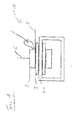
- FIG. 1 an inventive voltage converter 1 is shown, which is designed for 20 kV.
- the voltage converter 1 comprises a primary coil 2, a secondary coil 3 and a coil core 4.
- the secondary coil 3 is arranged around the core 4, while the primary coil 2 is arranged around the secondary coil 3.
- the voltage converter 1 operates on the principle of a transformer, wherein a voltage applied to the primary coil 2 higher AC voltage is transformed to a lower AC voltage at the secondary coil 3.
- the primary coil 2 has leads 5 for connection to a power supply network.
- the secondary coil 3 has connections for connection to a measuring device. For reasons of clarity, the abovementioned connections of the secondary coil and the measuring device are in FIG. 1 not shown.
- a capacity 6 is provided in the voltage converter 1 in FIG. 1 .
- This capacitor 6 is connected in parallel with the lowest 10% of the layers of the primary coil 2.
- the capacitance 6 is chosen such that a pole-zero compensation occurs in the region of the first resonance of the coil arrangement of the voltage converter.
- the transmission behavior of the voltage converter 1 in the range up to the first resonance is improved such that a substantially distortion-free transmission of high-frequency Harmonics and thus a review of the voltage quality in low or medium voltage networks is possible.
- FIG. 2 illustrates where the advantages of the inductive voltage converter 1 according to FIG. 1 become clear compared to a conventional inductive voltage converter.
- a usual inductive voltage converter while a voltage converter is referred to in which no parallel to the primary coil connected capacitance is provided.
- the phase response remains almost constant over a wide frequency range (up to approx. 12 kHz) starting from 0 Hz.
- significant distortions are already visible from about 2 kHz. Because of these distortions, a typical inductive voltage converter for the determination of the voltage quality in a power supply network, in particular a low or medium voltage network, not or only partially suitable.
- phase response is also in a wide, starting from 0 Hz frequency range (up to 12 kHz) almost constant. Compared to a conventional voltage converter, however, the amplitude response up to a frequency of about 11 kHz is almost constant. Due to this advantageous transmission behavior of the voltage converter is according to FIG. 1 well suited for the determination of the voltage quality in a power supply network and in particular in a low or medium voltage network.
- FIG. 3 a second embodiment of a voltage converter 1 according to the invention is shown.
- the basic structure of this voltage converter 1 is comparable to that of FIG. 1 , Reference is therefore made to the above statements and below only the differences in the voltage transformers 1 mentioned.
- the primary coil 2, the secondary coil 3 and the coil core 4 are cast in a cast resin insulation 7. Also cast in the cast resin insulation 7 is an externally accessible terminal box 8, in which the capacitor 6 is arranged interchangeable.
- the capacitance is connected in parallel via connecting lines 9 to the lowermost two layers of the primary coil 1.
- one connecting line 9 is connected to the primary coil 1, more precisely to the second lowermost layer of the primary coil 1, while the other connecting line 9 is connected to the feed line 5.
- the connecting lines 9 are also cast in the G cumharzisolation.
- the capacity 6 By arranging the capacity 6 in the externally accessible terminal box 8 a simple interchangeability of the capacity 6 is ensured. This makes it possible to respond to production fluctuations in the manufacture of a voltage converter 1 according to the invention and to use a capacity 6 adapted to any deviations in the frequency response of the voltage converter, in order to achieve the desired Pol-zero compensation or the substantially constant frequency response to reach the first resonant frequency of the coil assembly of the voltage converter 1. It is also possible to simply replace the capacity 6 in case of failure or due to possible aging phenomena without the voltage converter 1 having to be replaced altogether.
Landscapes
- Engineering & Computer Science (AREA)
- Power Engineering (AREA)
- Coils Of Transformers For General Uses (AREA)
- Transformers For Measuring Instruments (AREA)
Abstract
Description
- Die Erfindung betrifft induktive Spannungswandler und insbesondere Nieder- und Mittelspannungswandler.
- In den elektrischen Energieversorgungsnetzen, insbesondere in Nieder- und Mittelspannungsnetzen (bis 1 kV bzw. zwischen 1 kV und 75 kV) treten vermehrt Oberschwingungen auf. Diese Oberschwingungen werden vorwiegend von regenerativen Erzeugungsanlagen und Abnehmern mit Frequenzumrichtern verursacht und beeinträchtigen die sog. "Power Quality" bzw. die Spannungsqualität eines Energieversorgungsnetzes negativ. Um eine gewünschte Spannungsqualität in einem Energieversorgungsnetz zu gewährleisten, ist es zunächst erforderlich, die tatsächlich vorhandene Spannungsqualität zu ermitteln.
- Oberschwingungen können durch einen THD-Wert ("Total harmonic distortion" bzw. "gesamte harmonische Verzerrung") quantifiziert werden. Der THD ist definiert als das Verhältnis des Effektivwertes der Summe aller Oberschwingungsanteile zum Effektivwert der Grundschwingung und lässt sich wie folgt berechnen:

- In dieser Berechnung bedeutet Un die Effektivwertspannung Ueff der harmonischen Oberschwingungen n mit n>1 bzw. der Grundschwingung n=1.
- Der Anteil an Oberschwingungen bzw. der THD-Wert muss für eine akzeptable Spannungsqualität gemäß den geltenden VDE- und IEC-Bestimmungen in Nieder- und Mittelspannungsnetzen im Frequenzbereich bis 2,5 kHz unter 0,08 liegen. Darüber hinaus wird empfohlen, dass der THD-Wert im Frequenzbereich zwischen 2,5 kHz und 9 kHz die Grenze von 0,002 nicht überschreitet. Es gelten für die einzelnen Oberschwingungen ebenfalls individuelle Werte, die eingehalten werden müssen. Um die Einhaltung dieser Grenzen zu überprüfen, sollen vorzugsweise Spannungswandler mit nachgeschalteten Messeinrichtungen zum Einsatz kommen.
- Mit Spannungswandlern soll die Nieder- und Mittelspannung aus dem Energieversorgungsnetz derart herabgesetzt werden, dass für niedrige Spannungen ausgelegte und damit kostengünstige Messeinrichtungen zum Einsatz kommen können, um Spannung oder Spannungsverläufe in einem Nieder- oder Mittelspannungsnetz zu messen. Aus den Ergebnissen der Messeinrichtungen, die hinter einem Spannungswandler angeordnet sind, lassen sich Rückschlüsse auf die Verhältnisse im jeweiligen Nieder- oder Mittelspannungsnetz ziehen, insbesondere auch hinsichtlich der Spannungsqualität.
- Grundsätzlich sind als Spannungswandler induktive Spannungswandler bekannt. Diese funktionieren nach dem Prinzip des Transformators. Entsprechende Spannungswandler besitzen jedoch grundsätzlich Eigenschwingungen im für die Oberschwingungen in Nieder- und Mittelspannungsnetzen relevanten Frequenzbereich, welche die Übertragung im Spannungswandler stören. So kann beispielsweise ein induktiver 20-kV-Spannungswandler gemäß dem Stand der Technik Eigenschwingungen im Frequenzbereich von 2 kHz bis 15 kHz aufweisen, wobei das Übersetzungsverhältnis des Spannungswandlers bereits ab 1,5 kHz so stark beeinflusst sein kann, dass eine Messung der Oberschwingungen mithilfe eines entsprechenden Spannungswandlers nicht möglich ist. Es kommt also im Prinzip zu einer Begrenzung des Frequenzbands, wodurch nur Frequenzen unter 1,5 kHz akzeptabel übertragen werden können. Eine Bestimmung von Oberschwingungen in einem Nieder- oder Mittelspannungsnetz über 1,5 kHz ist mit einem induktiven Spannungswandler gemäß dem Stand der Technik daher nicht oder nur eingeschränkt möglich. Für die Überprüfung der THD-Werte in Nieder- und Mittelspannungsnetzen gilt das Gleiche.
- Um Oberschwingungen in Nieder- oder Mittelspannungsnetzen ausreichend genau messen zu können, wird grundsätzlich gefordert, dass dafür vorgesehene Spannungswandler zumindest bis 2,5 kHz ein konstantes Übertragungsverhalten aufweisen. Weiterhin wird empfohlen, dass die Spannungswandler auch bis zu 9 kHz ein konstantes Übertragungsverhalten aufweisen. Dabei werden maximale Fehler kleiner als 5 % erwünscht.
- Um ein entsprechendes Übertragungsverhalten zu erreichen, wurde im Stand der Technik versucht, die störenden Eigenschwingungen eines induktiven Spannungswandlers durch parallel geschaltete Kondensatoren an der Stirnseite der Primärspule zu reduzieren, wobei der Kondensator die Spule von deren Mitte bis zu dem mit der Erdung verbundenen äußeren Ende überspannt.
- Die Kondensatoren bei entsprechenden Spannungswandlern müssen eine hohe Spannungs aushalten und sind in der Folge einer gewissen Alterung ausgesetzt, bei der sich die Kapazität des Kondensators ändern kann. Durch eine Änderung der Kapazität ändert sich jedoch das Eigenschwingungsverhalten der Kombination aus Spannungswandler und Kondensator, so dass ein für die Überprüfung der Spannungsqualität bevorzugtes konstantes Übertragungsverhalten nicht gewährleistet werden kann.
- Aufgrund der hohen Anforderungen an die Spannungsfestigkeit und der damit ggf. verbundenen Alterung, welche eine intensive Wartung erfordern kann, ist der Einsatz entsprechender Spannungswandler in Schaltanlagen unpraktikabel oder gar unmöglich.
- Der Erfindung liegt die Aufgabe zugrunde, einen wartungsarmen Spannungswandler zu schaffen, der dazu ausgebildet ist, die Oberschwingungen in Nieder- oder Mittelspannungsnetzen derart übertragen zu können, dass die Oberschwingungen mit einer nachgeschalteten Messeinrichtung zur Bestimmung der Spannungsqualität im Nieder- oder Mittelspannungsnetz ausreichend genau während der gesamten Lebensdauer des Wandlers erfasst werden können.
- Gelöst wird diese Aufgabe durch einen Spannungswandler gemäß dem Hauptanspruch. Vorteilhafte Weiterbildungen sind Gegenstand der abhängigen Ansprüche.
- Demnach betrifft die Erfindung Spannungswandler umfassend eine Primärspule, wenigstens eine Sekundärspule und einen Spulenkern, wobei die wenigstens eine Sekundärspule um den Spulenkern und die Primärspule um die wenigstens eine Sekundärspule angeordnet ist, wobei eine Kapazität parallel zu den Lagen der Primärspule vorgesehen ist, bei der die Kapazität parallel zu den untersten Lagen der Primärspule geschaltet ist, wobei die Anzahl der untersten Lagen kleiner ist als die Hälfte der Anzahl aller Lagen der Primärspule.
- Bei den "untersten Lagen der Primärspule" handelt es sich um diejenigen Windungs- bzw. Wicklungslagen der Primärspule, die innenliegend und damit dem Spulenkern nächstliegend sind. Insbesondere umfasst der Begriff der "untersten Lagen der Primärspule" auch die unterste Lage der Primärspule. Eine Primärspule eines Spannungswandlers für Nieder- und Mittelspannungen hat typischerweise wenigstens 2, wenigstens 10 oder wenigstens 20 Lagen.
- Durch die erfindungsgemäß parallel geschaltete Kapazität kann eine Pol-Nullstellenkompensation der ersten Resonanz der Spulenanordnung des Spannungswandlers erreicht werden, wobei ähnlich wie im Stand der Technik durch den Fachmann eine jeweils von der Größe her geeignete Kapazität zu ermitteln ist, welche die gewünschte Kompensation zur Folge hat. Durch eine entsprechende Pol-Nullstellenkompensation verbessert sich das Übertragungsverhalten des Spannungswandlers bis hin zu der ersten Resonanz erheblich. Der Erfindung liegt dabei die Erkenntnis zugrunde, dass trotz der gegenüber dem Stand der Technik geringeren Anzahl an Lagen, zu denen die Kapazität parallel geschaltet ist, durch die erfindungsgemäße Anordnung der Kapazität ein nahezu lineares Übertragungsverhalten in einem breiten Frequenzbereich ausgehend von und größer als 0 Hz erreicht werden kann, welches für den Einsatz als Messspannungswandler für Nieder- und Mittelspannungsnetze vorteilhaft ist und die gewünschte Verbesserung über einen größeren Frequenzbereich bringt.
- Da bei dem erfindungsgemäßen Spannungswandler - anders als im Stand der Technik - die Kapazität nicht parallel zur Hälfte der Lagen der Primärspule, sondern zu einer geringeren Anzahl an Lagen geschaltet ist, ist es grundsätzlich ausreichend, wenn die Kapazität eine geringere Spannungsfestigkeit aufweist. In der Folge können kostengünstigere Kapazitäten bzw. Kondensatoren verwendet werden.
- Da die Kapazität bei der erfindungsgemäßen Lösung gegenüber dem Stand der Technik weiterhin grundsätzlich mit weniger Spannung belastet wird, können kostengünstigere Kondensatoren verwendet werden. Auch fallen evtl. Alterungseffekte geringer aus.
- Die Kapazität kann parallel zu den untersten 10 % der Lagen der Primärspule, vorzugsweise zu den untersten 5 % der Lagen der Primärspule, weiter vorzugsweise zu den untersten 3 % der Lagen der Primärspule geschaltet sein. Es ist auch möglich, dass die Kapazität parallel nur zu der untersten oder den beiden untersten Lagen der Primärspule geschaltet ist. Die Kapazität ist dabei jeweils derart zu wählen, dass die gewünschte Pol-Nullstellenkompensation bei der ersten Resonanz erreicht wird. Die für die gewünschte Pol-Nullstellenkompensation geeignete Kapazität kann bspw. durch Versuche ermittelt werden.
- Zur Parallelschaltung mit den untersten Lagen der Primärspule kann die Kapazität mit ihrem einen Anschluss mit der Zuleitung zur untersten Lage der Primärspule verbunden sein. Der andere Anschluss der Kapazität ist weiterhin an der Primärspule selbst angeschlossen, um die erfindungsgemäße Parallelschaltung zu erreichen. Durch den Anschluss an der Zuleitung wird die Herstellung eines erfindungsgemäßen Spannungswandlers vereinfacht und somit kostengünstiger möglich.
- Spannungswandler für Nieder- und Mittelspannungen sind in der Regel gießharzisoliert, d. h., die einzelnen Komponenten des Spannungswandlers sind vollständig vom Gießharz umschlossen. Das Gießharz füllt dabei den Raum um die Spulen und wirkt somit als ein von Luft verschiedenes Dielektrikum, wodurch sich auch das Frequenzverhalten des Spannungswandlers ändert. Die Gießharzisolation aus dem Stand der Technik umfasst die Primärspule, die wenigstens eine Sekundärspule, den Spulenkern sowie den parallel geschalteten Kondensator.
- Der erfindungsgemäße Spannungswandler weist vorzugsweise ebenfalls eine Gießharzisolation auf, wobei jedoch die Kapazität außerhalb der Gießharzisolation angeordnet ist. In anderen Worten umschließt die Gießharzisolation also die Primärspule, die wenigstens eine Sekundärspule und den Spulenkern, nicht jedoch die Kapazität, die parallel zu den untersten Lagen der Primärspule geschaltet ist. Die Anordnung der Kapazität außerhalb der Gießharzisolation kann beispielsweise mithilfe von Anschlussleitungen, die sich durch die Gießharzisolation erstrecken, erreicht werden.
- Die Anordnung der Kapazität außerhalb der Gießharzisolation bietet mehrere Vorteile. So kann auf eine aufwendige Polsterung der Kapazität, wie sie im Falle einer Anordnung eines Kondensators in der Gießharzisolation aufgrund von Schrumpfungsprozessen während des Aushärtens der Isolation notwendig ist, verzichtet werden. Auch ist es möglich, die Kapazität noch auf im Produktionsprozess unvermeidliche Abweichungen (bspw. bei der Aushärtung der Gießharzisolation) auf die dielektrischen Verhältnisse des Spannungswandlers, die bedeutende Auswirkungen auf dessen Frequenzgang haben können, einzustellen, indem ggf. eine individuell ermittelte Kapazität vorgesehen wird. Dadurch kann bei den Spannungswandlern trotz unvermeidlicher Produktionsabweichungen ein optimaler Frequenzgang gewährleistet werden.
- Es ist weiter bevorzugt, wenn die Kapazität austauschbar ausgestaltet ist. Dadurch wird ein einfacher Austausch bei Ausfall oder evtl. Alterungseffekten der Kapazität ermöglicht, ohne dass der gesamte Spannungswandler ausgetauscht werden müsste. Die Kapazität kann dabei bspw. in einen von außen zugänglichen Klemmenkasten angeordnet sein, wobei der Klemmenkasten selbst ggf. teilweise in die Gießharzisolation eingegossen ist.
- Die Erfindung wird anhand von Ausführungsbeispielen unter Bezugnahme auf die beigefügten Zeichnungen beispielhaft beschrieben. Es zeigen:
- Figur 1:
- eine schematische Darstellung eines ersten Ausführungsbeispiels eines erfindungsgemäßen Spannungswandlers;
- Figur 2:
- das Übertragungsverhalten eines gewöhnlichen induktiven Spannungswandlers und eines induktiven Spannungswandlers gemäß
Figur 1 ; und - Figur 3:
- eine schematische Darstellung eines zweiten Ausführungsbeispiels eines erfindungsgemäßen Spannungswandlers.
- In
Figur 1 ist ein erfindungsgemäßer Spannungswandler 1 dargestellt, der für 20 kV ausgelegt ist. Der Spannungswandler 1 umfasst eine Primärspule 2, eine Sekundärspule 3 und einen Spulenkern 4. Die Sekundärspule 3 ist dabei um den Kern 4 angeordnet, während die Primärspule 2 um die Sekundärspule 3 angeordnet ist. Der Spannungswandler 1 funktioniert nach dem Prinzip eines Transformators, wobei eine an der Primärspule 2 anliegende höhere Wechselspannung auf eine niedrigere Wechselspannung an der Sekundärspule 3 transformiert wird. Die Primärspule 2 weist Zuleitungen 5 zum Anschluss an ein Energieversorgungsnetz auf. Die Sekundärspule 3 weist Anschlüsse zum Anschluss an eine Messeinrichtung auf. Aus Gründen der Übersichtlichkeit sind die genannten Anschlüsse der Sekundärspule sowie die Messeinrichtung inFigur 1 nicht dargestellt. - Bei dem Spannungswandler 1 in
Figur 1 ist eine Kapazität 6 vorgesehen. Diese Kapazität 6 ist parallel zu den untersten 10 % der Lagen der Primärspule 2 geschaltet. Die Kapazität 6 ist dabei so gewählt, dass eine Pol-Nullstellenkompensation im Bereich der ersten Resonanz der Spulenanordnung des Spannungswandlers kommt. - Durch eine entsprechende Kompensation wird das Übertragungsverhalten des Spannungswandlers 1 im Bereich bis zur ersten Resonanz derart verbessert, dass auch eine im Wesentlichen verzerrungsfreie Übertragung von hochfrequenten Oberschwingungen und somit eine Überprüfung der Spannungsqualität in Nieder- oder Mittelspannungsnetzen möglich wird.
- Diese Verbesserung des Übertragungsverhaltens wird anhand von
Figur 2 veranschaulicht, wo die Vorteile des induktiven Spannungswandlers 1 gemäßFigur 1 gegenüber einem gewöhnlichen induktiven Spannungswandler deutlich werden. Als gewöhnlicher induktiver Spannungswandler wird dabei ein Spannungswandler bezeichnet, bei dem keine zur Primärspule parallel geschaltete Kapazität vorgesehen ist. - Bei dem in
Figur 2 links dargestellten gewöhnlichen induktiven Spannungswandler bleibt der Phasengang in einem weiten, von 0 Hz ausgehenden Frequenzbereich (bis ca. 12 kHz) nahezu konstant. Im Amplitudengang über denselben Frequenzbereich werden jedoch bereits ab ca. 2 kHz deutliche Verzerrungen sichtbar. Aufgrund dieser Verzerrungen ist ein gewöhnlicher induktiver Spannungswandler für die Bestimmung der Spannungsqualität in einem Energieversorgungsnetz, insbesondere einem Nieder- oder Mittelspannungsnetz, nicht bzw. nur bedingt geeignet. - Bei einem Spannungswandler gemäß
Figur 1 , dessen Amplituden- und Phasengang rechts inFigur 2 dargestellt sind, ist der Phasengang ebenfalls in einem weiten, von 0 Hz ausgehenden Frequenzbereich (bis ca. 12 kHz) nahezu konstant. Gegenüber eines gewöhnlichen Spannungswandlers ist jedoch auch der Amplitudengang bis zu einer Frequenz von ca. 11 kHz nahezu konstant. Aufgrund dieses vorteilhaften Übertragungsverhaltens ist der Spannungswandler gemäßFigur 1 für die Bestimmung der Spannungsqualität in einem Energieversorgungsnetz und insbesondere auch in einem Nieder- oder Mittelspannungsnetz gut geeignet. - In
Figur 3 ist ein zweites Ausführungsbeispiel eines erfindungsgemäßen Spannungswandlers 1 dargestellt. Der grundsätzliche Aufbau dieses Spannungswandlers 1 ist vergleichbar mit demjenigen ausFigur 1 . Es wird daher auf die obigen Ausführungen verwiesen und im Folgenden nur auf die Unterschiede bei den genannten Spannungswandlern 1 eingegangen. - Bei dem Spannungswandler 1 gemäß
Figur 3 sind die Primärspule 2, die Sekundärspule 3 sowie der Spulenkern 4 in eine Gießharzisolation 7 eingegossen. Ebenfalls in die Gießharzisolation 7 eingegossen ist ein von außen zugänglicher Klemmenkasten 8, in dem die Kapazität 6 austauschbar angeordnet ist. Die Kapazität ist dabei über Anschlussleitungen 9 zu den untersten beiden Lagen der Primärspule 1 parallel geschaltet. Dazu ist die eine Anschlussleitung 9 mit der Primärspule 1, genauer mit der zweit-untersten Lage der Primärspule 1, verbunden, während die andere Anschlussleitung 9 mit der Zuleitung 5 verbunden ist. Die Anschlussleitungen 9 sind ebenfalls in die Gießharzisolation eingegossen. - Durch die Anordnung der Kapazität 6 im von außen zugänglichen Klemmenkasten 8 ist eine einfache Austauschbarkeit der Kapazität 6 gewährleistet. Dadurch ist es möglich, auf Produktionsschwankungen bei der Herstellung eines erfindungsgemäßen Spannungswandlers 1 zu reagieren und eine an evtl. auftretende Abweichungen im Frequenzgang des Spannungswandlers angepasste Kapazität 6 zu verwenden, um die gewünschte Pol-Nullstellenkompensation bzw. den im Wesentlichen konstanten Frequenzgang bis zur ersten Resonanzfrequenz der Spulenanordnung des Spannungswandlers 1 zu erreichen. Auch ist es möglich, die Kapazität 6 bei Ausfall oder wegen evtl. Alterungserscheinungen einfach auszutauschen, ohne dass der Spannungswandler 1 insgesamt ausgetauscht werden müsste.
Claims (7)
- Spannungswandler (1) umfassend eine Primärspule (2), wenigstens eine Sekundärspule (3) und einen Spulenkern (4), wobei die wenigstens eine Sekundärspule (3) um den Spulenkern (4) und die Primärspule (2) um die wenigstens eine Sekundärspule (3) angeordnet ist, wobei eine Kapazität (6) parallel zu den Lagen der Primärspule (6) vorgesehen ist,
dadurch gekennzeichnet, dass
die Kapazität (6) parallel zu den untersten Lagen der Primärspule (2) geschaltet ist, wobei die Anzahl der untersten Lagen kleiner ist als die Hälfte der Anzahl aller Lagen der Primärspule (2). - Spannungswandler nach Anspruch 1,
dadurch gekennzeichnet, dass
die Kapazität (6) parallel zu den untersten 10 % der Lagen der Primärspule (2), vorzugsweise zu den untersten 5 % der Lagen der Primärspule(2), weiter vorzugsweise zu den untersten 3 % der Lagen der Primärspule (2) geschaltet ist. - Spannungswandler nach Anspruch 1,
dadurch gekennzeichnet, dass
die Kapazität (6) parallel zu der untersten oder den beiden untersten Lagen der Primärspule (1) geschaltet ist. - Spannungswandler nach einem der vorhergehenden Ansprüche,
dadurch gekennzeichnet, dass
die Kapazität (6) mit ihrem einen Anschluss mit einer der Zuleitungen (5) der Primärspule (1) verbunden ist. - Spannungswandler nach einem der vorhergehenden Ansprüche,
dadurch gekennzeichnet, dass
eine Gießharzisolation (7) vorgesehen ist, die die Primärspule (2), die Sekundärspule (3) und den Spulenkern (4) vollständig umschließt, wobei die Kapazität (6) außerhalb der Gießharzisolation (7) angeordnet ist. - Spannungswandler nach Anspruch 5,
dadurch gekennzeichnet, dass
die Kapazität (6) austauschbar, vorzugsweise in einem von außen zugänglichen Klemmenkasten (8), angeordnet ist. - Spannungswandler nach einem der vorhergehenden Ansprüche,
dadurch gekennzeichnet, dass
die Primärspule (2) wenigstens 2, vorzugsweise wenigstens 10, weiter vorzugsweise wenigstens 20 Lagen aufweist.
Applications Claiming Priority (1)
| Application Number | Priority Date | Filing Date | Title |
|---|---|---|---|
| DE102013225657.4A DE102013225657A1 (de) | 2013-12-11 | 2013-12-11 | Induktiver Spannungswandler |
Publications (2)
| Publication Number | Publication Date |
|---|---|
| EP2897142A1 true EP2897142A1 (de) | 2015-07-22 |
| EP2897142B1 EP2897142B1 (de) | 2018-04-04 |
Family
ID=52013869
Family Applications (1)
| Application Number | Title | Priority Date | Filing Date |
|---|---|---|---|
| EP14195814.0A Active EP2897142B1 (de) | 2013-12-11 | 2014-12-02 | Induktiver Spannungswandler |
Country Status (2)
| Country | Link |
|---|---|
| EP (1) | EP2897142B1 (de) |
| DE (1) | DE102013225657A1 (de) |
Citations (1)
| Publication number | Priority date | Publication date | Assignee | Title |
|---|---|---|---|---|
| DE102012205784A1 (de) * | 2012-04-10 | 2013-10-10 | Gottfried Wilhelm Leibniz Universität Hannover | Spannungswandler |
-
2013
- 2013-12-11 DE DE102013225657.4A patent/DE102013225657A1/de not_active Withdrawn
-
2014
- 2014-12-02 EP EP14195814.0A patent/EP2897142B1/de active Active
Patent Citations (1)
| Publication number | Priority date | Publication date | Assignee | Title |
|---|---|---|---|---|
| DE102012205784A1 (de) * | 2012-04-10 | 2013-10-10 | Gottfried Wilhelm Leibniz Universität Hannover | Spannungswandler |
Also Published As
| Publication number | Publication date |
|---|---|
| EP2897142B1 (de) | 2018-04-04 |
| DE102013225657A1 (de) | 2015-06-11 |
Similar Documents
| Publication | Publication Date | Title |
|---|---|---|
| EP2438450B1 (de) | Vorrichtung zur prüfung von geräten der hochspannungstechnik | |
| EP2622615B1 (de) | Anordnung und verfahren zur kompensation eines magnetischen gleichflusses in einem transformatorkern | |
| EP2133888A1 (de) | Prüfanordnung zur Wechselspannungsprüfung von elektrischen Hochspannungskomponenten | |
| WO2013127555A1 (de) | Prüfsystem und verfahren zur prüfung von geräten der hochspannungstechnik | |
| DE2501405A1 (de) | Stromwandler | |
| EP2897142B1 (de) | Induktiver Spannungswandler | |
| EP2651020B1 (de) | Spannungswandler | |
| DE102012105046A1 (de) | Referenzmesssystem zum Kalibrieren eines Leistungsmesssystems für Leistungstransformatoren | |
| EP2685581A1 (de) | Versorgung eines Schienenfahrzeugs mit elektrischer Energie über eine abgeschirmte Energieversorgungsleitung | |
| EP2897141B1 (de) | Induktiver Spannungswandler | |
| DE2452056A1 (de) | Induktiver spannungswandler fuer eine mittels isoliergas vollisolierte, metallgekapselte hochspannungsschaltanlage | |
| EP3133615B1 (de) | Elektrische wicklungsanordnung | |
| DE571127C (de) | Schaltungsanordnung zur Beseitigung von Rundfunkstoerungen | |
| DE69912523T2 (de) | Begrenzungseinrichtung für Hochspannungsleistungsschalter mit einem geerdeten Gehäuse | |
| DE2710827C3 (de) | Anordnung zur Prüfung der Oberspannungswicklung eines fertig montierten induktiven Spannungswandlers | |
| CH314113A (de) | Aus Scheibenspulen aufgebaute Röhrenwicklung, insbesondere für Transformatoren und Drosseln | |
| DE966783C (de) | Anordnung zum Entnehmen kleiner Leistung aus Hochspannungsnetzen mittels kapazitiver Spannungsteilung | |
| AT202221B (de) | Stromwandler für Höchstspannungsanlagen | |
| DE950942C (de) | Transformator fuer den UEbergang von einem elektrisch symmetrischen System auf ein unsymmetrisches und umgekehrt | |
| DE837127C (de) | Ausgleichsverfahren zur Verminderung der Geraeuschstoerungen bei mehrlagigen Fernmeldekabeln | |
| DE432982C (de) | Anzeigevorrichtung zum selektiven Erkennen einer mit Erdschluss behafteten Zweigleitung eines Hochspannungsnetzes | |
| DE502770C (de) | Einrichtung zur Kompensation des Erdschlussstromes von Hochspannungsleitungen | |
| DE717827C (de) | Einrichtung zur Erdschlussloeschung und bzw. oder zur Beeinflussung der Lage des Erdpunktes | |
| AT100921B (de) | Anordnung zur Messung der Spannung in Hochspannungsnetzen. | |
| AT117398B (de) | Vorrichtung zur Prüfung der durch Erdschlußspulen erzielten Kompensation des Erdschlußstromes. |
Legal Events
| Date | Code | Title | Description |
|---|---|---|---|
| PUAI | Public reference made under article 153(3) epc to a published international application that has entered the european phase |
Free format text: ORIGINAL CODE: 0009012 |
|
| 17P | Request for examination filed |
Effective date: 20141202 |
|
| AK | Designated contracting states |
Kind code of ref document: A1 Designated state(s): AL AT BE BG CH CY CZ DE DK EE ES FI FR GB GR HR HU IE IS IT LI LT LU LV MC MK MT NL NO PL PT RO RS SE SI SK SM TR |
|
| AX | Request for extension of the european patent |
Extension state: BA ME |
|
| 17P | Request for examination filed |
Effective date: 20160108 |
|
| RBV | Designated contracting states (corrected) |
Designated state(s): AL AT BE BG CH CY CZ DE DK EE ES FI FR GB GR HR HU IE IS IT LI LT LU LV MC MK MT NL NO PL PT RO RS SE SI SK SM TR |
|
| GRAP | Despatch of communication of intention to grant a patent |
Free format text: ORIGINAL CODE: EPIDOSNIGR1 |
|
| STAA | Information on the status of an ep patent application or granted ep patent |
Free format text: STATUS: GRANT OF PATENT IS INTENDED |
|
| INTG | Intention to grant announced |
Effective date: 20170822 |
|
| GRAS | Grant fee paid |
Free format text: ORIGINAL CODE: EPIDOSNIGR3 |
|
| GRAJ | Information related to disapproval of communication of intention to grant by the applicant or resumption of examination proceedings by the epo deleted |
Free format text: ORIGINAL CODE: EPIDOSDIGR1 |
|
| GRAL | Information related to payment of fee for publishing/printing deleted |
Free format text: ORIGINAL CODE: EPIDOSDIGR3 |
|
| STAA | Information on the status of an ep patent application or granted ep patent |
Free format text: STATUS: REQUEST FOR EXAMINATION WAS MADE |
|
| INTC | Intention to grant announced (deleted) | ||
| GRAP | Despatch of communication of intention to grant a patent |
Free format text: ORIGINAL CODE: EPIDOSNIGR1 |
|
| STAA | Information on the status of an ep patent application or granted ep patent |
Free format text: STATUS: GRANT OF PATENT IS INTENDED |
|
| GRAA | (expected) grant |
Free format text: ORIGINAL CODE: 0009210 |
|
| STAA | Information on the status of an ep patent application or granted ep patent |
Free format text: STATUS: THE PATENT HAS BEEN GRANTED |
|
| INTG | Intention to grant announced |
Effective date: 20180213 |
|
| AK | Designated contracting states |
Kind code of ref document: B1 Designated state(s): AL AT BE BG CH CY CZ DE DK EE ES FI FR GB GR HR HU IE IS IT LI LT LU LV MC MK MT NL NO PL PT RO RS SE SI SK SM TR |
|
| REG | Reference to a national code |
Ref country code: GB Ref legal event code: FG4D Free format text: NOT ENGLISH |
|
| REG | Reference to a national code |
Ref country code: CH Ref legal event code: EP |
|
| REG | Reference to a national code |
Ref country code: AT Ref legal event code: REF Ref document number: 986434 Country of ref document: AT Kind code of ref document: T Effective date: 20180415 |
|
| REG | Reference to a national code |
Ref country code: IE Ref legal event code: FG4D Free format text: LANGUAGE OF EP DOCUMENT: GERMAN |
|
| REG | Reference to a national code |
Ref country code: DE Ref legal event code: R096 Ref document number: 502014007828 Country of ref document: DE |
|
| REG | Reference to a national code |
Ref country code: NL Ref legal event code: MP Effective date: 20180404 |
|
| REG | Reference to a national code |
Ref country code: LT Ref legal event code: MG4D |
|
| PG25 | Lapsed in a contracting state [announced via postgrant information from national office to epo] |
Ref country code: NL Free format text: LAPSE BECAUSE OF FAILURE TO SUBMIT A TRANSLATION OF THE DESCRIPTION OR TO PAY THE FEE WITHIN THE PRESCRIBED TIME-LIMIT Effective date: 20180404 |
|
| PG25 | Lapsed in a contracting state [announced via postgrant information from national office to epo] |
Ref country code: ES Free format text: LAPSE BECAUSE OF FAILURE TO SUBMIT A TRANSLATION OF THE DESCRIPTION OR TO PAY THE FEE WITHIN THE PRESCRIBED TIME-LIMIT Effective date: 20180404 Ref country code: LT Free format text: LAPSE BECAUSE OF FAILURE TO SUBMIT A TRANSLATION OF THE DESCRIPTION OR TO PAY THE FEE WITHIN THE PRESCRIBED TIME-LIMIT Effective date: 20180404 Ref country code: FI Free format text: LAPSE BECAUSE OF FAILURE TO SUBMIT A TRANSLATION OF THE DESCRIPTION OR TO PAY THE FEE WITHIN THE PRESCRIBED TIME-LIMIT Effective date: 20180404 Ref country code: BG Free format text: LAPSE BECAUSE OF FAILURE TO SUBMIT A TRANSLATION OF THE DESCRIPTION OR TO PAY THE FEE WITHIN THE PRESCRIBED TIME-LIMIT Effective date: 20180704 Ref country code: PL Free format text: LAPSE BECAUSE OF FAILURE TO SUBMIT A TRANSLATION OF THE DESCRIPTION OR TO PAY THE FEE WITHIN THE PRESCRIBED TIME-LIMIT Effective date: 20180404 Ref country code: SE Free format text: LAPSE BECAUSE OF FAILURE TO SUBMIT A TRANSLATION OF THE DESCRIPTION OR TO PAY THE FEE WITHIN THE PRESCRIBED TIME-LIMIT Effective date: 20180404 Ref country code: AL Free format text: LAPSE BECAUSE OF FAILURE TO SUBMIT A TRANSLATION OF THE DESCRIPTION OR TO PAY THE FEE WITHIN THE PRESCRIBED TIME-LIMIT Effective date: 20180404 Ref country code: NO Free format text: LAPSE BECAUSE OF FAILURE TO SUBMIT A TRANSLATION OF THE DESCRIPTION OR TO PAY THE FEE WITHIN THE PRESCRIBED TIME-LIMIT Effective date: 20180704 |
|
| PG25 | Lapsed in a contracting state [announced via postgrant information from national office to epo] |
Ref country code: HR Free format text: LAPSE BECAUSE OF FAILURE TO SUBMIT A TRANSLATION OF THE DESCRIPTION OR TO PAY THE FEE WITHIN THE PRESCRIBED TIME-LIMIT Effective date: 20180404 Ref country code: GR Free format text: LAPSE BECAUSE OF FAILURE TO SUBMIT A TRANSLATION OF THE DESCRIPTION OR TO PAY THE FEE WITHIN THE PRESCRIBED TIME-LIMIT Effective date: 20180705 Ref country code: LV Free format text: LAPSE BECAUSE OF FAILURE TO SUBMIT A TRANSLATION OF THE DESCRIPTION OR TO PAY THE FEE WITHIN THE PRESCRIBED TIME-LIMIT Effective date: 20180404 Ref country code: RS Free format text: LAPSE BECAUSE OF FAILURE TO SUBMIT A TRANSLATION OF THE DESCRIPTION OR TO PAY THE FEE WITHIN THE PRESCRIBED TIME-LIMIT Effective date: 20180404 |
|
| PG25 | Lapsed in a contracting state [announced via postgrant information from national office to epo] |
Ref country code: PT Free format text: LAPSE BECAUSE OF FAILURE TO SUBMIT A TRANSLATION OF THE DESCRIPTION OR TO PAY THE FEE WITHIN THE PRESCRIBED TIME-LIMIT Effective date: 20180806 |
|
| REG | Reference to a national code |
Ref country code: DE Ref legal event code: R097 Ref document number: 502014007828 Country of ref document: DE |
|
| PG25 | Lapsed in a contracting state [announced via postgrant information from national office to epo] |
Ref country code: CZ Free format text: LAPSE BECAUSE OF FAILURE TO SUBMIT A TRANSLATION OF THE DESCRIPTION OR TO PAY THE FEE WITHIN THE PRESCRIBED TIME-LIMIT Effective date: 20180404 Ref country code: RO Free format text: LAPSE BECAUSE OF FAILURE TO SUBMIT A TRANSLATION OF THE DESCRIPTION OR TO PAY THE FEE WITHIN THE PRESCRIBED TIME-LIMIT Effective date: 20180404 Ref country code: SK Free format text: LAPSE BECAUSE OF FAILURE TO SUBMIT A TRANSLATION OF THE DESCRIPTION OR TO PAY THE FEE WITHIN THE PRESCRIBED TIME-LIMIT Effective date: 20180404 Ref country code: EE Free format text: LAPSE BECAUSE OF FAILURE TO SUBMIT A TRANSLATION OF THE DESCRIPTION OR TO PAY THE FEE WITHIN THE PRESCRIBED TIME-LIMIT Effective date: 20180404 Ref country code: DK Free format text: LAPSE BECAUSE OF FAILURE TO SUBMIT A TRANSLATION OF THE DESCRIPTION OR TO PAY THE FEE WITHIN THE PRESCRIBED TIME-LIMIT Effective date: 20180404 |
|
| PLBE | No opposition filed within time limit |
Free format text: ORIGINAL CODE: 0009261 |
|
| STAA | Information on the status of an ep patent application or granted ep patent |
Free format text: STATUS: NO OPPOSITION FILED WITHIN TIME LIMIT |
|
| PG25 | Lapsed in a contracting state [announced via postgrant information from national office to epo] |
Ref country code: IT Free format text: LAPSE BECAUSE OF FAILURE TO SUBMIT A TRANSLATION OF THE DESCRIPTION OR TO PAY THE FEE WITHIN THE PRESCRIBED TIME-LIMIT Effective date: 20180404 Ref country code: SM Free format text: LAPSE BECAUSE OF FAILURE TO SUBMIT A TRANSLATION OF THE DESCRIPTION OR TO PAY THE FEE WITHIN THE PRESCRIBED TIME-LIMIT Effective date: 20180404 |
|
| 26N | No opposition filed |
Effective date: 20190107 |
|
| PG25 | Lapsed in a contracting state [announced via postgrant information from national office to epo] |
Ref country code: SI Free format text: LAPSE BECAUSE OF FAILURE TO SUBMIT A TRANSLATION OF THE DESCRIPTION OR TO PAY THE FEE WITHIN THE PRESCRIBED TIME-LIMIT Effective date: 20180404 |
|
| REG | Reference to a national code |
Ref country code: CH Ref legal event code: PL |
|
| PG25 | Lapsed in a contracting state [announced via postgrant information from national office to epo] |
Ref country code: LU Free format text: LAPSE BECAUSE OF NON-PAYMENT OF DUE FEES Effective date: 20181202 Ref country code: MC Free format text: LAPSE BECAUSE OF FAILURE TO SUBMIT A TRANSLATION OF THE DESCRIPTION OR TO PAY THE FEE WITHIN THE PRESCRIBED TIME-LIMIT Effective date: 20180404 |
|
| REG | Reference to a national code |
Ref country code: IE Ref legal event code: MM4A |
|
| REG | Reference to a national code |
Ref country code: BE Ref legal event code: MM Effective date: 20181231 |
|
| PG25 | Lapsed in a contracting state [announced via postgrant information from national office to epo] |
Ref country code: IE Free format text: LAPSE BECAUSE OF NON-PAYMENT OF DUE FEES Effective date: 20181202 |
|
| PG25 | Lapsed in a contracting state [announced via postgrant information from national office to epo] |
Ref country code: BE Free format text: LAPSE BECAUSE OF NON-PAYMENT OF DUE FEES Effective date: 20181231 |
|
| PG25 | Lapsed in a contracting state [announced via postgrant information from national office to epo] |
Ref country code: LI Free format text: LAPSE BECAUSE OF NON-PAYMENT OF DUE FEES Effective date: 20181231 Ref country code: CH Free format text: LAPSE BECAUSE OF NON-PAYMENT OF DUE FEES Effective date: 20181231 |
|
| PG25 | Lapsed in a contracting state [announced via postgrant information from national office to epo] |
Ref country code: MT Free format text: LAPSE BECAUSE OF FAILURE TO SUBMIT A TRANSLATION OF THE DESCRIPTION OR TO PAY THE FEE WITHIN THE PRESCRIBED TIME-LIMIT Effective date: 20180404 |
|
| PG25 | Lapsed in a contracting state [announced via postgrant information from national office to epo] |
Ref country code: TR Free format text: LAPSE BECAUSE OF FAILURE TO SUBMIT A TRANSLATION OF THE DESCRIPTION OR TO PAY THE FEE WITHIN THE PRESCRIBED TIME-LIMIT Effective date: 20180404 |
|
| PG25 | Lapsed in a contracting state [announced via postgrant information from national office to epo] |
Ref country code: MK Free format text: LAPSE BECAUSE OF NON-PAYMENT OF DUE FEES Effective date: 20180404 Ref country code: HU Free format text: LAPSE BECAUSE OF FAILURE TO SUBMIT A TRANSLATION OF THE DESCRIPTION OR TO PAY THE FEE WITHIN THE PRESCRIBED TIME-LIMIT; INVALID AB INITIO Effective date: 20141202 Ref country code: CY Free format text: LAPSE BECAUSE OF FAILURE TO SUBMIT A TRANSLATION OF THE DESCRIPTION OR TO PAY THE FEE WITHIN THE PRESCRIBED TIME-LIMIT Effective date: 20180404 |
|
| PG25 | Lapsed in a contracting state [announced via postgrant information from national office to epo] |
Ref country code: IS Free format text: LAPSE BECAUSE OF FAILURE TO SUBMIT A TRANSLATION OF THE DESCRIPTION OR TO PAY THE FEE WITHIN THE PRESCRIBED TIME-LIMIT Effective date: 20180804 |
|
| P01 | Opt-out of the competence of the unified patent court (upc) registered |
Effective date: 20230525 |
|
| PGFP | Annual fee paid to national office [announced via postgrant information from national office to epo] |
Ref country code: DE Payment date: 20251218 Year of fee payment: 12 |
|
| PGFP | Annual fee paid to national office [announced via postgrant information from national office to epo] |
Ref country code: GB Payment date: 20251218 Year of fee payment: 12 |
|
| PGFP | Annual fee paid to national office [announced via postgrant information from national office to epo] |
Ref country code: AT Payment date: 20251215 Year of fee payment: 12 |
|
| PGFP | Annual fee paid to national office [announced via postgrant information from national office to epo] |
Ref country code: FR Payment date: 20251218 Year of fee payment: 12 |