EP2897003B1 - Movement and mechanical timepiece including a chronograph mechanism - Google Patents
Movement and mechanical timepiece including a chronograph mechanism Download PDFInfo
- Publication number
- EP2897003B1 EP2897003B1 EP15151310.8A EP15151310A EP2897003B1 EP 2897003 B1 EP2897003 B1 EP 2897003B1 EP 15151310 A EP15151310 A EP 15151310A EP 2897003 B1 EP2897003 B1 EP 2897003B1
- Authority
- EP
- European Patent Office
- Prior art keywords
- chronograph
- friction spring
- chronograph mechanism
- movement
- movement according
- Prior art date
- Legal status (The legal status is an assumption and is not a legal conclusion. Google has not performed a legal analysis and makes no representation as to the accuracy of the status listed.)
- Active
Links
- 238000005265 energy consumption Methods 0.000 claims description 6
- 210000000056 organ Anatomy 0.000 claims description 2
- 230000008878 coupling Effects 0.000 claims 7
- 238000010168 coupling process Methods 0.000 claims 7
- 238000005859 coupling reaction Methods 0.000 claims 7
- 230000001105 regulatory effect Effects 0.000 description 3
- 240000008042 Zea mays Species 0.000 description 1
- 238000006073 displacement reaction Methods 0.000 description 1
- 230000005021 gait Effects 0.000 description 1
- 238000009413 insulation Methods 0.000 description 1
- 238000003754 machining Methods 0.000 description 1
- 230000001960 triggered effect Effects 0.000 description 1
Images


Classifications
-
- G—PHYSICS
- G04—HOROLOGY
- G04B—MECHANICALLY-DRIVEN CLOCKS OR WATCHES; MECHANICAL PARTS OF CLOCKS OR WATCHES IN GENERAL; TIME PIECES USING THE POSITION OF THE SUN, MOON OR STARS
- G04B1/00—Driving mechanisms
- G04B1/10—Driving mechanisms with mainspring
- G04B1/22—Compensation of changes in the motive power of the mainspring
- G04B1/225—Compensation of changes in the motive power of the mainspring with the aid of an interposed power-accumulator (secondary spring) which is always tensioned
-
- G—PHYSICS
- G04—HOROLOGY
- G04F—TIME-INTERVAL MEASURING
- G04F7/00—Apparatus for measuring unknown time intervals by non-electric means
- G04F7/04—Apparatus for measuring unknown time intervals by non-electric means using a mechanical oscillator
- G04F7/08—Watches or clocks with stop devices, e.g. chronograph
- G04F7/0823—Watches or clocks with stop devices, e.g. chronograph with couplings between the chronograph mechanism and the base movement
-
- G—PHYSICS
- G04—HOROLOGY
- G04F—TIME-INTERVAL MEASURING
- G04F7/00—Apparatus for measuring unknown time intervals by non-electric means
- G04F7/04—Apparatus for measuring unknown time intervals by non-electric means using a mechanical oscillator
- G04F7/08—Watches or clocks with stop devices, e.g. chronograph
- G04F7/0842—Watches or clocks with stop devices, e.g. chronograph with start-stop control mechanisms
- G04F7/0857—Watches or clocks with stop devices, e.g. chronograph with start-stop control mechanisms with single push-button or actuation member for start-stop and reset
Definitions
- the present invention relates to a watch movement and to a timepiece comprising a chronograph mechanism.
- Movements and mechanical timepieces comprising an existing chronograph mechanism have drawbacks such as variation in the movement of the movement, amplitude variations of the regulating member, between the different operating states, particularly on or off the chronograph. These variations in the course of the movement or the isochronism of the regulating organ come at least partly from the fact that the energy consumed is not the same depending on the function, on or off in particular, engaged.
- CH242662 discloses a mechanical clockwork according to the preamble of claim 1.
- One of the aims of the present invention is to homogenize the energy consumption regardless of the function or the functions engaged and to stabilize the amplitude variations of the regulating member between the different operating states of the movement.
- the present invention relates to a watch movement comprising a chronograph mechanism obviating the aforementioned drawbacks which is distinguished by the features set forth in claim 1.
- the invention also relates to a timepiece comprising a movement as enumerated in claim 1.
- the present invention relates to a watch movement and a mechanical timepiece comprising a chronograph mechanism.
- the movement comprises a barrel or motor member, a power train connecting the barrel to a driving wheel, called a field wheel 1, pivoted on a fixed part of the movement and a chronograph wheel 2, also pivoted on a fixed part of the movement, the axis 3 is integral with a core 4.
- This movement further comprises an intermediate rocker or clutch rocker 5 pivoted on a fixed part of the movement in A by a first end and the second end, free, 5.1 cooperates in a conventional manner with a column wheel 6 also rotated on a fixed part of the movement.
- the intermediate lever 5 carries an intermediate wheel 7 pivoted freely on this intermediate lever and meshes permanently with the field wheel 1.
- a large rocker 8 subjected to the action of a control pushbutton 9 accessible from outside the timepiece causes, for each pressure on the control pushbutton 9 step by step, the column wheel 6 thanks to its ratchet 8.1.
- the novelty and originality of the present watchmaking movement lies in the addition of a friction spring 10 fixed on a fixed part of the movement, generally the plate P thereof, passing close to the axis 1.1 of the field wheel 1 and extending beyond this axis until it is superimposed on the intermediate lever 5.
- this friction spring is free, that is to say it passes next to the axis 1.1. of the field wheel 1 and that its free end is in contact with nothing.
- this free end of the friction spring is able to come into contact with an adjustable eccentric abutment 11 carried by the intermediate lever 5.
- the abutment 11 can be fixed on the intermediate lever 5 and formed by a pin or a machining thereof.
- the principle of the present invention which makes it possible to minimize or even cancel the amplitude variations of a mechanical clockwork movement comprising a chronograph mechanism therefore consists in adding a friction spring to the field wheel which consumes the energy when the chronograph is triggered, when stopped.
- the friction of the friction spring consumes no energy when the chronograph is running.
- the intermediate lever or chronograph clutch serves as control of the friction spring and carries an eccentric that allows the adjustment of the spring tension and therefore of the energy consumed by the friction of this spring on the axis of the wheel of field.
- the tension of the spring is adjusted by means of the eccentric so that the energy consumption of the friction spring, when the chronograph is at a standstill, is equivalent to the energy that the chronograph consumes when he is engaged.
- the column wheel 6 can be replaced by a cam in a known manner.
- the column wheel 6 or the cam thus forms a control member of the intermediate lever 5.
- the free end of the friction spring 10 is located in the path of a stop 11, adjustable or not, and its middle portion is adapted to be applied against the axis 1.1. of the field wheel 1.
- the stop is carried by the intermediate rocker 5 or, in variants, on another appropriate part of the clutch system of the chronograph mechanism.
- the friction spring 10 can be mounted on or integrated with the intermediate lever 5.
- the friction spring 10 is in the rest state in contact against the axis 1.1 of the field wheel 1 and it is the stop 11 carried by the intermediate rocker 5 which displaces the friction spring 10 at the moment of the switching on the chronograph to separate said spring 11 from the axis 1.1 of the field wheel 1.
Landscapes
- Physics & Mathematics (AREA)
- General Physics & Mathematics (AREA)
- Measurement Of Unknown Time Intervals (AREA)
Description
La présente invention se rapporte à un mouvement d'horlogerie ainsi qu'à une pièce d'horlogerie comprenant un mécanisme de chronographe.The present invention relates to a watch movement and to a timepiece comprising a chronograph mechanism.
Les mouvements et pièces d'horlogerie mécanique comprenant un mécanisme de chronographe existants présentent des inconvénients tels que variation de la marche du mouvement, variations d'amplitude de l'organe réglant, entre les différents états de fonctionnement notamment marche ou arrêt du chronographe. Ces variations de la marche du mouvement ou de l'isochronisme de l'organe réglant proviennent pour partie au moins du fait que l'énergie consommée n'est pas la même suivant la fonction, marche ou arrêt notamment, enclenchée.
L'un des buts de la présente invention est d'homogénéiser la consommation d'énergie quelle que soit la fonction ou les fonctions enclenchées et de stabiliser les variations d'amplitude de l'organe réglant entre les différents états de fonctionnement du mouvement.One of the aims of the present invention is to homogenize the energy consumption regardless of the function or the functions engaged and to stabilize the amplitude variations of the regulating member between the different operating states of the movement.
La présente invention a pour objet un mouvement d'horlogerie comportant un mécanisme de chronographe obviant aux inconvénients précités qui se distingue par les caractéristiques énoncées à la revendication 1.The present invention relates to a watch movement comprising a chronograph mechanism obviating the aforementioned drawbacks which is distinguished by the features set forth in claim 1.
L'invention a également pour objet une pièce d'horlogerie comportant un mouvement tel qu'énuméré à la revendication 1.The invention also relates to a timepiece comprising a movement as enumerated in claim 1.
Le dessin annexé illustre schématiquement et partiellement, à titre d'exemple, deux formes d'exécution du mouvement d'horlogerie selon l'invention.
- La
figure 1 est une vue partielle d'un mouvement vu de dessous, côté ponts, selon une première forme d'exécution de l'invention, le mécanisme de chronographe étant à l'arrêt. - La
figure 2 est une vue similaire à lafigure 1 , le mécanisme chronographe étant en marche. - La
figure 3 illustre en plan un détail de lafigure 1 . - La
figure 4 illustre en plan un détail de lafigure 2 . - Les
figures 5 à 8 sont des figures semblables auxfigures 1 à 4 mais pour une seconde forme d'exécution de l'invention.
- The
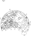
figure 1 is a partial view of a movement seen from below, bridges side, according to a first embodiment of the invention, the chronograph mechanism being stopped. - The
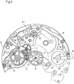
figure 2 is a view similar to thefigure 1 , the chronograph mechanism being in operation. - The
figure 3 illustrates in plan a detail of thefigure 1 . - The
figure 4 illustrates in plan a detail of thefigure 2 . - The
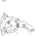
Figures 5 to 8 are figures similar toFigures 1 to 4 but for a second embodiment of the invention.
La présente invention a pour objet un mouvement d'horlogerie et une pièce d'horlogerie mécanique comportant un mécanisme de chronographe. Le mouvement comporte à l'instar des mouvements existants de ce type un barillet ou organe moteur, un rouage moteur reliant le barillet à une roue entraîneuse, dite roue de champ 1, pivotée sur une partie fixe du mouvement et une roue de chronographe 2, également pivotée sur une partie fixe du mouvement, dont l'axe 3 est solidaire d'un coeur 4. Ce mouvement comporte encore une bascule intermédiaire ou bascule d'embrayage 5 pivotée sur une partie fixe du mouvement en A par une première extrémité et dont la seconde extrémité, libre, 5.1 coopère de façon classique avec une roue à colonne 6 également pivotée sur une partie fixe du mouvement.The present invention relates to a watch movement and a mechanical timepiece comprising a chronograph mechanism. Like the existing movements of this type, the movement comprises a barrel or motor member, a power train connecting the barrel to a driving wheel, called a field wheel 1, pivoted on a fixed part of the movement and a
La bascule intermédiaire 5 porte une roue intermédiaire 7 pivotée librement sur cette bascule intermédiaire et engrenant en permanence avec la roue de champ 1.The
De façon classique, une grande bascule 8 soumise à l'action d'un poussoir de commande 9 accessible de l'extérieur de la pièce d'horlogerie entraîne, pour chaque pression sur le poussoir de commande 9 pas à pas, la roue à colonne 6 grâce à son cliquet 8.1.Conventionally, a
Toujours de façon classique lorsque la seconde extrémité libre 5.1 de la bascule intermédiaire 5 s'appuie sur une colonne de la roue à colonne 6, la roue intermédiaire 7 n'engrène pas avec la roue de chronographe 2 et le chronographe est à l'arrêt (voir
Par contre, lorsque la seconde extrémité libre 5.1 de la bascule intermédiaire 5 tombe entre deux colonnes de la roue à colonne 6, la bascule intermédiaire 5 bascule sous l'action de son ressort de rappel 5.2 et la roue intermédiaire 7 vient s'engrener avec la roue de chronographe 2, le mécanisme de chronographe est en marche (voir
La nouveauté et l'originalité du présent mouvement d'horlogerie réside dans l'adjonction d'un ressort de friction 10 fixé sur une partie fixe du mouvement, généralement la platine P de celui-ci, passant à proximité de l'axe 1.1 de la roue de champ 1 et s'étendant au-delà de cet axe jusqu'à se superposer à la bascule intermédiaire 5. En position de marche du chronographe (
Comme on le voit sur le dessin, cette extrémité libre du ressort de friction est apte à entrer en contact avec une butée excentrique réglable 11 portée par la bascule intermédiaire 5.As can be seen in the drawing, this free end of the friction spring is able to come into contact with an adjustable
Lorsque le chronographe est mis à l'arrêt (
Dans une variante, la butée 11 peut être fixe sur la bascule intermédiaire 5 et formée par une goupille ou un usinage de celle-ci.In a variant, the
De cette manière, on remplace l'énergie consommée par la marche du chronographe par une friction sur l'axe de la roue de champ 1 lorsque le chronographe est à l'arrêt. Ainsi, la consommation d'énergie est toujours sensiblement la même que le chronographe soit en marche ou à l'arrêt. Ceci étant, on a supprimé la cause des variations de marche et d'isochronisme ou d'amplitude du balancier et la marche du mouvement devient indépendante de l'état de marche ou d'arrêt du chronographe.In this way, the energy consumed by the chronograph operation is replaced by friction on the axis of the field wheel 1 when the chronograph is stopped. Thus, the energy consumption is still substantially the same whether the chronograph is on or off. This being the case, the cause of the variations of gait and isochronism or amplitude has been removed. the pendulum and the movement of the movement becomes independent of the state of operation or stopping of the chronograph.
Le principe de la présente invention qui permet de minimiser voir d'annuler les variations d'amplitude d'un mouvement d'horlogerie mécanique comportant un mécanisme de chronographe consiste donc à ajouter un ressort de friction sur la roue de champ qui consomme de l'énergie lorsque le chronographe est déclenché, à l'arrêt. Le frottement du ressort de friction ne consomme aucune énergie lorsque le chronographe est en marche. La bascule intermédiaire ou d'embrayage de chronographe fait office de commande du ressort de friction et porte un excentrique qui permet le réglage de la tension du ressort et donc de l'énergie consommée par la friction de ce ressort sur l'axe de la roue de champ. On ajuste la tension du ressort à l'aide de l'excentrique de manière à ce que la consommation d'énergie du ressort de friction, lorsque le chronographe est à l'arrêt, soit équivalente à l'énergie que le chronographe consomme lorsqu'il est enclenché.The principle of the present invention which makes it possible to minimize or even cancel the amplitude variations of a mechanical clockwork movement comprising a chronograph mechanism therefore consists in adding a friction spring to the field wheel which consumes the energy when the chronograph is triggered, when stopped. The friction of the friction spring consumes no energy when the chronograph is running. The intermediate lever or chronograph clutch serves as control of the friction spring and carries an eccentric that allows the adjustment of the spring tension and therefore of the energy consumed by the friction of this spring on the axis of the wheel of field. The tension of the spring is adjusted by means of the eccentric so that the energy consumption of the friction spring, when the chronograph is at a standstill, is equivalent to the energy that the chronograph consumes when he is engaged.
On a ainsi réalisé l'homogénéisation de la consommation d'énergie selon l'état d'enclenchement ou non des fonctions chronographe et rattrapante si le mécanisme de chronographe comporte une rattrapante avec isolation.It has thus been realized that the energy consumption is homogenized according to the state of engagement or not of the chronograph and catch-up functions if the chronograph mechanism comprises an override with insulation.
Dans des variantes la roue à colonne 6 peut être remplacée par une came de façon connue. La roue à colonne 6 ou la came forme donc un organe de commande de la bascule intermédiaire 5.In variants, the
Dans toutes les réalisations possibles l'extrémité libre du ressort de friction 10 est située sur le chemin d'une butée 11, réglable ou non, et sa portion médiane est apte à être appliquée contre l'axe 1.1. de la roue de champ 1. La butée est portée par la bascule intermédiaire 5 ou, dans des variantes, sur une autre partie appropriée du système d'embrayage du mécanisme de chronographe.In all possible embodiments the free end of the
Dans une variante le ressort de friction 10 peut être monté sur ou intégré à la bascule intermédiaire 5.In a variant, the
Le principe d'ajout d'un ressort consommateur d'énergie pour homogénéiser la consommation d'énergie quelles que soient les fonctions enclenchées peut être également appliqué à un chronographe à embrayage vertical.The principle of adding a power-consuming spring to homogenize energy consumption regardless of the functions engaged can also be applied to a chronograph with vertical clutch.
Dans une second forme d'exécution (
Claims (14)
- A mechanical horological movement comprising a chronograph mechanism including a driving wheel (1) connected by a gear train to a motor organ of the movement and driven in rotation independently of the running or stopped state of the chronograph mechanism and a chronograph wheel (2) adapted, in the running position of the chronograph mechanism, to be driven by the driving wheel (1), the chronograph wheel (2) not being driven by the driving wheel (1) when the chronograph mechanism is stopped, characterised in that it comprises a friction spring (10) arranged to rub on the driving wheel (1) when the chronograph mechanism is stopped.
- The movement according to claim 1, characterised in that the friction spring (10) is controlled by a coupling system (5) of the chronograph mechanism.
- The movement according to claim 2, characterised in that the friction spring (10) has a free end located in the path of a abutment (11) carried by the coupling system (5) of the chronograph mechanism, the middle part of the friction spring (10) being adapted to be applied against the driving wheel (1).
- The movement according to claim 3, characterised in that the abutment (11) is adjustable.
- The movement according to one of claims 2 to 4, characterised in that the coupling system of the chronograph mechanism comprises an intermediate lever or a coupling lever (5).
- The movement according to claim 5, characterised in that the friction spring (10) is attached to or integrated with the intermediate lever or with the coupling lever (5).
- The movement according to claim 6, characterised in that the abutment (11) is carried by the intermediate lever or the coupling lever (5) and is an adjustable eccentric element allowing adjustment of the tension of the friction spring (10).
- The movement according to one of the preceding claims 1 to 5, characterised in that the friction spring (10) is attached to a fixed part of the movement.
- The movement according to one of the preceding claims, characterised in that the friction spring (10) is arranged so that in the stop position of the chronograph, said friction spring (10) is pushed against the driving wheel (1) by the abutment (11) of the coupling system (5) of the chronograph mechanism or by its own elasticity.
- The movement according to one of the preceding claims, characterised in that it is arranged so that, when the chronograph mechanism is stopped, the energy consumed by the friction of the driving wheel (1) against the friction spring (10) is substantially equal to the energy consumed by the chronograph wheel (2) when the chronograph mechanism is running.
- The movement according to one of the preceding claims, characterised in that it is arranged so that its energy consumption is substantially the same regardless whether the chronograph mechanism is running or stopped.
- The movement according to one of the preceding claims, characterised in that the friction spring (10) is arranged so that in the running position of the chronograph mechanism, said friction spring (10) is not in contact with the driving wheel (1).
- The mechanism according to one of the preceding claims, characterised in that the friction spring (10) is arranged to rub on the axis (1.1) of the driving wheel (1) when the chronograph mechanism is stopped.
- A timepiece comprising a mechanical horological movement according to one of the preceding claims.
Applications Claiming Priority (1)
| Application Number | Priority Date | Filing Date | Title |
|---|---|---|---|
| CH00054/14A CH709154A1 (en) | 2014-01-16 | 2014-01-16 | Movement and mechanical timepiece including a chronograph mechanism. |
Publications (3)
| Publication Number | Publication Date |
|---|---|
| EP2897003A2 EP2897003A2 (en) | 2015-07-22 |
| EP2897003A3 EP2897003A3 (en) | 2016-04-06 |
| EP2897003B1 true EP2897003B1 (en) | 2018-11-21 |
Family
ID=52394915
Family Applications (1)
| Application Number | Title | Priority Date | Filing Date |
|---|---|---|---|
| EP15151310.8A Active EP2897003B1 (en) | 2014-01-16 | 2015-01-15 | Movement and mechanical timepiece including a chronograph mechanism |
Country Status (2)
| Country | Link |
|---|---|
| EP (1) | EP2897003B1 (en) |
| CH (1) | CH709154A1 (en) |
Families Citing this family (5)
| Publication number | Priority date | Publication date | Assignee | Title |
|---|---|---|---|---|
| EP3324249A1 (en) * | 2016-11-17 | 2018-05-23 | Nogerah SA | Clutch system for chronograph |
| EP3327518B1 (en) | 2016-11-29 | 2020-03-18 | Montres Breguet S.A. | Timepiece comprising a switching device of a clockwork mechanism |
| CH715923B1 (en) * | 2019-03-14 | 2022-03-15 | Lvmh Swiss Mft Sa C/O Zenith Succursale De Lvmh Swiss Mft Sa | Lateral clutch device for chronograph with two transmissions and chronograph watch movement comprising such a device. |
| NL2023822B1 (en) * | 2019-09-12 | 2021-05-17 | Flexous Mech Ip B V | Chronograph watch |
| NL2023823B1 (en) * | 2019-09-12 | 2021-05-17 | Flexous Mech Ip B V | Watch |
Family Cites Families (4)
| Publication number | Priority date | Publication date | Assignee | Title |
|---|---|---|---|---|
| GB310987A (en) * | 1928-01-06 | 1929-05-06 | Charles Vernon Boys | Improvements in means for equalizing the drive in clocks and clock-governed mechanism |
| CH242662A (en) * | 1944-07-18 | 1946-05-31 | Girard Erwin | Chronograph. |
| CH580301B5 (en) * | 1973-07-10 | 1976-09-30 | Suisse Horlogerie | |
| EP1498788A1 (en) * | 2003-07-14 | 2005-01-19 | Eterna SA | Display device for timepiece |
-
2014
- 2014-01-16 CH CH00054/14A patent/CH709154A1/en not_active Application Discontinuation
-
2015
- 2015-01-15 EP EP15151310.8A patent/EP2897003B1/en active Active
Non-Patent Citations (1)
| Title |
|---|
| None * |
Also Published As
| Publication number | Publication date |
|---|---|
| EP2897003A2 (en) | 2015-07-22 |
| EP2897003A3 (en) | 2016-04-06 |
| CH709154A1 (en) | 2015-07-31 |
Similar Documents
| Publication | Publication Date | Title |
|---|---|---|
| EP2897003B1 (en) | Movement and mechanical timepiece including a chronograph mechanism | |
| EP3059641B1 (en) | Oscillator with a detent escapement | |
| EP2541346A2 (en) | Device for resetting a component indicating a time-related magnitude to a predetermined position | |
| EP3059643A1 (en) | Chronograph mechanism | |
| CH705075A2 (en) | Shockproof device for absorbing shocks subjected by shaft of balance spring of clock movement of watch, has adjustment unit adjusting pre-stressing of elastic part when elastic part is mounted in support ring | |
| EP2241945B1 (en) | Chronograph mechanism and timepiece equipped with such mechanism | |
| EP2251747A2 (en) | Chronograph mechanism and timepiece provided with such a chronograph mechanism | |
| EP2221678A1 (en) | Device for blocking a resonator of a timepiece | |
| EP2500785B1 (en) | Chronograph mechanism and timepiece provided with such a mechanism | |
| EP3644134B1 (en) | Stopping device for oscillating system | |
| FR3090912A1 (en) | WINDER WITH BUMPER SYSTEM | |
| CH291567A (en) | Timepiece. | |
| CH370709A (en) | Thin frame element for watch movement | |
| CH714372A2 (en) | Mechanism for correcting a function of a movement of a timepiece. | |
| CH281802A (en) | Automatic winding watch movement with double effect by oscillating weight. | |
| CH441474A (en) | Push-button operated switch for house installation | |
| EP2690510B1 (en) | Timepiece display mechanism | |
| CH157096A (en) | Chronograph wristwatch. | |
| EP4357857A1 (en) | Hairspring for timepiece resonator mechanism provided with means for adjusting the stiffness | |
| CH720136A2 (en) | Spiral spring for a watch resonator mechanism provided with means for adjusting the stiffness. | |
| CH336014A (en) | Friction spring | |
| CH330190A (en) | Self-winding timepiece | |
| CH245132A (en) | Automatic winding mechanism with oscillating weight. | |
| CH716149A1 (en) | Clockwork movement comprising at least one gong. | |
| CH408785A (en) | Device for winding the mainspring of a clockwork movement |
Legal Events
| Date | Code | Title | Description |
|---|---|---|---|
| PUAI | Public reference made under article 153(3) epc to a published international application that has entered the european phase |
Free format text: ORIGINAL CODE: 0009012 |
|
| 17P | Request for examination filed |
Effective date: 20150115 |
|
| AK | Designated contracting states |
Kind code of ref document: A2 Designated state(s): AL AT BE BG CH CY CZ DE DK EE ES FI FR GB GR HR HU IE IS IT LI LT LU LV MC MK MT NL NO PL PT RO RS SE SI SK SM TR |
|
| AX | Request for extension of the european patent |
Extension state: BA ME |
|
| PUAL | Search report despatched |
Free format text: ORIGINAL CODE: 0009013 |
|
| AK | Designated contracting states |
Kind code of ref document: A3 Designated state(s): AL AT BE BG CH CY CZ DE DK EE ES FI FR GB GR HR HU IE IS IT LI LT LU LV MC MK MT NL NO PL PT RO RS SE SI SK SM TR |
|
| AX | Request for extension of the european patent |
Extension state: BA ME |
|
| RIC1 | Information provided on ipc code assigned before grant |
Ipc: G04F 7/08 20060101AFI20160303BHEP Ipc: G04B 1/22 20060101ALI20160303BHEP |
|
| RAP1 | Party data changed (applicant data changed or rights of an application transferred) |
Owner name: MONTBLANC MONTRE SA |
|
| 17P | Request for examination filed |
Effective date: 20160929 |
|
| RBV | Designated contracting states (corrected) |
Designated state(s): AL AT BE BG CH CY CZ DE DK EE ES FI FR GB GR HR HU IE IS IT LI LT LU LV MC MK MT NL NO PL PT RO RS SE SI SK SM TR |
|
| STAA | Information on the status of an ep patent application or granted ep patent |
Free format text: STATUS: EXAMINATION IS IN PROGRESS |
|
| 17Q | First examination report despatched |
Effective date: 20180119 |
|
| GRAP | Despatch of communication of intention to grant a patent |
Free format text: ORIGINAL CODE: EPIDOSNIGR1 |
|
| STAA | Information on the status of an ep patent application or granted ep patent |
Free format text: STATUS: GRANT OF PATENT IS INTENDED |
|
| INTG | Intention to grant announced |
Effective date: 20180710 |
|
| GRAS | Grant fee paid |
Free format text: ORIGINAL CODE: EPIDOSNIGR3 |
|
| GRAA | (expected) grant |
Free format text: ORIGINAL CODE: 0009210 |
|
| STAA | Information on the status of an ep patent application or granted ep patent |
Free format text: STATUS: THE PATENT HAS BEEN GRANTED |
|
| AK | Designated contracting states |
Kind code of ref document: B1 Designated state(s): AL AT BE BG CH CY CZ DE DK EE ES FI FR GB GR HR HU IE IS IT LI LT LU LV MC MK MT NL NO PL PT RO RS SE SI SK SM TR |
|
| REG | Reference to a national code |
Ref country code: CH Ref legal event code: EP Ref country code: CH Ref legal event code: NV Representative=s name: MICHELI AND CIE SA, CH |
|
| REG | Reference to a national code |
Ref country code: IE Ref legal event code: FG4D Free format text: LANGUAGE OF EP DOCUMENT: FRENCH |
|
| REG | Reference to a national code |
Ref country code: DE Ref legal event code: R096 Ref document number: 602015019945 Country of ref document: DE |
|
| REG | Reference to a national code |
Ref country code: AT Ref legal event code: REF Ref document number: 1068277 Country of ref document: AT Kind code of ref document: T Effective date: 20181215 |
|
| REG | Reference to a national code |
Ref country code: NL Ref legal event code: MP Effective date: 20181121 |
|
| REG | Reference to a national code |
Ref country code: AT Ref legal event code: MK05 Ref document number: 1068277 Country of ref document: AT Kind code of ref document: T Effective date: 20181121 |
|
| PG25 | Lapsed in a contracting state [announced via postgrant information from national office to epo] |
Ref country code: AT Free format text: LAPSE BECAUSE OF FAILURE TO SUBMIT A TRANSLATION OF THE DESCRIPTION OR TO PAY THE FEE WITHIN THE PRESCRIBED TIME-LIMIT Effective date: 20181121 Ref country code: NO Free format text: LAPSE BECAUSE OF FAILURE TO SUBMIT A TRANSLATION OF THE DESCRIPTION OR TO PAY THE FEE WITHIN THE PRESCRIBED TIME-LIMIT Effective date: 20190221 Ref country code: LV Free format text: LAPSE BECAUSE OF FAILURE TO SUBMIT A TRANSLATION OF THE DESCRIPTION OR TO PAY THE FEE WITHIN THE PRESCRIBED TIME-LIMIT Effective date: 20181121 Ref country code: FI Free format text: LAPSE BECAUSE OF FAILURE TO SUBMIT A TRANSLATION OF THE DESCRIPTION OR TO PAY THE FEE WITHIN THE PRESCRIBED TIME-LIMIT Effective date: 20181121 Ref country code: IS Free format text: LAPSE BECAUSE OF FAILURE TO SUBMIT A TRANSLATION OF THE DESCRIPTION OR TO PAY THE FEE WITHIN THE PRESCRIBED TIME-LIMIT Effective date: 20190321 Ref country code: BG Free format text: LAPSE BECAUSE OF FAILURE TO SUBMIT A TRANSLATION OF THE DESCRIPTION OR TO PAY THE FEE WITHIN THE PRESCRIBED TIME-LIMIT Effective date: 20190221 Ref country code: LT Free format text: LAPSE BECAUSE OF FAILURE TO SUBMIT A TRANSLATION OF THE DESCRIPTION OR TO PAY THE FEE WITHIN THE PRESCRIBED TIME-LIMIT Effective date: 20181121 Ref country code: HR Free format text: LAPSE BECAUSE OF FAILURE TO SUBMIT A TRANSLATION OF THE DESCRIPTION OR TO PAY THE FEE WITHIN THE PRESCRIBED TIME-LIMIT Effective date: 20181121 Ref country code: ES Free format text: LAPSE BECAUSE OF FAILURE TO SUBMIT A TRANSLATION OF THE DESCRIPTION OR TO PAY THE FEE WITHIN THE PRESCRIBED TIME-LIMIT Effective date: 20181121 |
|
| PG25 | Lapsed in a contracting state [announced via postgrant information from national office to epo] |
Ref country code: GR Free format text: LAPSE BECAUSE OF FAILURE TO SUBMIT A TRANSLATION OF THE DESCRIPTION OR TO PAY THE FEE WITHIN THE PRESCRIBED TIME-LIMIT Effective date: 20190222 Ref country code: NL Free format text: LAPSE BECAUSE OF FAILURE TO SUBMIT A TRANSLATION OF THE DESCRIPTION OR TO PAY THE FEE WITHIN THE PRESCRIBED TIME-LIMIT Effective date: 20181121 Ref country code: PT Free format text: LAPSE BECAUSE OF FAILURE TO SUBMIT A TRANSLATION OF THE DESCRIPTION OR TO PAY THE FEE WITHIN THE PRESCRIBED TIME-LIMIT Effective date: 20190321 Ref country code: AL Free format text: LAPSE BECAUSE OF FAILURE TO SUBMIT A TRANSLATION OF THE DESCRIPTION OR TO PAY THE FEE WITHIN THE PRESCRIBED TIME-LIMIT Effective date: 20181121 Ref country code: SE Free format text: LAPSE BECAUSE OF FAILURE TO SUBMIT A TRANSLATION OF THE DESCRIPTION OR TO PAY THE FEE WITHIN THE PRESCRIBED TIME-LIMIT Effective date: 20181121 Ref country code: RS Free format text: LAPSE BECAUSE OF FAILURE TO SUBMIT A TRANSLATION OF THE DESCRIPTION OR TO PAY THE FEE WITHIN THE PRESCRIBED TIME-LIMIT Effective date: 20181121 |
|
| PG25 | Lapsed in a contracting state [announced via postgrant information from national office to epo] |
Ref country code: PL Free format text: LAPSE BECAUSE OF FAILURE TO SUBMIT A TRANSLATION OF THE DESCRIPTION OR TO PAY THE FEE WITHIN THE PRESCRIBED TIME-LIMIT Effective date: 20181121 Ref country code: IT Free format text: LAPSE BECAUSE OF FAILURE TO SUBMIT A TRANSLATION OF THE DESCRIPTION OR TO PAY THE FEE WITHIN THE PRESCRIBED TIME-LIMIT Effective date: 20181121 Ref country code: CZ Free format text: LAPSE BECAUSE OF FAILURE TO SUBMIT A TRANSLATION OF THE DESCRIPTION OR TO PAY THE FEE WITHIN THE PRESCRIBED TIME-LIMIT Effective date: 20181121 Ref country code: DK Free format text: LAPSE BECAUSE OF FAILURE TO SUBMIT A TRANSLATION OF THE DESCRIPTION OR TO PAY THE FEE WITHIN THE PRESCRIBED TIME-LIMIT Effective date: 20181121 |
|
| REG | Reference to a national code |
Ref country code: DE Ref legal event code: R097 Ref document number: 602015019945 Country of ref document: DE |
|
| PG25 | Lapsed in a contracting state [announced via postgrant information from national office to epo] |
Ref country code: SK Free format text: LAPSE BECAUSE OF FAILURE TO SUBMIT A TRANSLATION OF THE DESCRIPTION OR TO PAY THE FEE WITHIN THE PRESCRIBED TIME-LIMIT Effective date: 20181121 Ref country code: RO Free format text: LAPSE BECAUSE OF FAILURE TO SUBMIT A TRANSLATION OF THE DESCRIPTION OR TO PAY THE FEE WITHIN THE PRESCRIBED TIME-LIMIT Effective date: 20181121 Ref country code: EE Free format text: LAPSE BECAUSE OF FAILURE TO SUBMIT A TRANSLATION OF THE DESCRIPTION OR TO PAY THE FEE WITHIN THE PRESCRIBED TIME-LIMIT Effective date: 20181121 Ref country code: SM Free format text: LAPSE BECAUSE OF FAILURE TO SUBMIT A TRANSLATION OF THE DESCRIPTION OR TO PAY THE FEE WITHIN THE PRESCRIBED TIME-LIMIT Effective date: 20181121 Ref country code: MC Free format text: LAPSE BECAUSE OF FAILURE TO SUBMIT A TRANSLATION OF THE DESCRIPTION OR TO PAY THE FEE WITHIN THE PRESCRIBED TIME-LIMIT Effective date: 20181121 |
|
| PLBE | No opposition filed within time limit |
Free format text: ORIGINAL CODE: 0009261 |
|
| STAA | Information on the status of an ep patent application or granted ep patent |
Free format text: STATUS: NO OPPOSITION FILED WITHIN TIME LIMIT |
|
| PG25 | Lapsed in a contracting state [announced via postgrant information from national office to epo] |
Ref country code: LU Free format text: LAPSE BECAUSE OF NON-PAYMENT OF DUE FEES Effective date: 20190115 |
|
| REG | Reference to a national code |
Ref country code: BE Ref legal event code: MM Effective date: 20190131 |
|
| 26N | No opposition filed |
Effective date: 20190822 |
|
| REG | Reference to a national code |
Ref country code: IE Ref legal event code: MM4A |
|
| PG25 | Lapsed in a contracting state [announced via postgrant information from national office to epo] |
Ref country code: SI Free format text: LAPSE BECAUSE OF FAILURE TO SUBMIT A TRANSLATION OF THE DESCRIPTION OR TO PAY THE FEE WITHIN THE PRESCRIBED TIME-LIMIT Effective date: 20181121 |
|
| PG25 | Lapsed in a contracting state [announced via postgrant information from national office to epo] |
Ref country code: BE Free format text: LAPSE BECAUSE OF NON-PAYMENT OF DUE FEES Effective date: 20190131 |
|
| PG25 | Lapsed in a contracting state [announced via postgrant information from national office to epo] |
Ref country code: IE Free format text: LAPSE BECAUSE OF NON-PAYMENT OF DUE FEES Effective date: 20190115 |
|
| PG25 | Lapsed in a contracting state [announced via postgrant information from national office to epo] |
Ref country code: TR Free format text: LAPSE BECAUSE OF FAILURE TO SUBMIT A TRANSLATION OF THE DESCRIPTION OR TO PAY THE FEE WITHIN THE PRESCRIBED TIME-LIMIT Effective date: 20181121 |
|
| PG25 | Lapsed in a contracting state [announced via postgrant information from national office to epo] |
Ref country code: MT Free format text: LAPSE BECAUSE OF FAILURE TO SUBMIT A TRANSLATION OF THE DESCRIPTION OR TO PAY THE FEE WITHIN THE PRESCRIBED TIME-LIMIT Effective date: 20181121 |
|
| PG25 | Lapsed in a contracting state [announced via postgrant information from national office to epo] |
Ref country code: CY Free format text: LAPSE BECAUSE OF FAILURE TO SUBMIT A TRANSLATION OF THE DESCRIPTION OR TO PAY THE FEE WITHIN THE PRESCRIBED TIME-LIMIT Effective date: 20181121 |
|
| PG25 | Lapsed in a contracting state [announced via postgrant information from national office to epo] |
Ref country code: HU Free format text: LAPSE BECAUSE OF FAILURE TO SUBMIT A TRANSLATION OF THE DESCRIPTION OR TO PAY THE FEE WITHIN THE PRESCRIBED TIME-LIMIT; INVALID AB INITIO Effective date: 20150115 |
|
| PG25 | Lapsed in a contracting state [announced via postgrant information from national office to epo] |
Ref country code: MK Free format text: LAPSE BECAUSE OF FAILURE TO SUBMIT A TRANSLATION OF THE DESCRIPTION OR TO PAY THE FEE WITHIN THE PRESCRIBED TIME-LIMIT Effective date: 20181121 |
|
| PGFP | Annual fee paid to national office [announced via postgrant information from national office to epo] |
Ref country code: DE Payment date: 20240119 Year of fee payment: 10 Ref country code: CH Payment date: 20240202 Year of fee payment: 10 Ref country code: GB Payment date: 20240123 Year of fee payment: 10 |
|
| PGFP | Annual fee paid to national office [announced via postgrant information from national office to epo] |
Ref country code: FR Payment date: 20240122 Year of fee payment: 10 |