EP2896375B1 - Bohrführung - Google Patents
Bohrführung Download PDFInfo
- Publication number
- EP2896375B1 EP2896375B1 EP15152599.5A EP15152599A EP2896375B1 EP 2896375 B1 EP2896375 B1 EP 2896375B1 EP 15152599 A EP15152599 A EP 15152599A EP 2896375 B1 EP2896375 B1 EP 2896375B1
- Authority
- EP
- European Patent Office
- Prior art keywords
- drill guide
- femoral
- arm
- intramedullary rod
- hole
- Prior art date
- Legal status (The legal status is an assumption and is not a legal conclusion. Google has not performed a legal analysis and makes no representation as to the accuracy of the status listed.)
- Active
Links
Images


Classifications
-
- A—HUMAN NECESSITIES
- A61—MEDICAL OR VETERINARY SCIENCE; HYGIENE
- A61B—DIAGNOSIS; SURGERY; IDENTIFICATION
- A61B17/00—Surgical instruments, devices or methods
- A61B17/16—Instruments for performing osteoclasis; Drills or chisels for bones; Trepans
- A61B17/17—Guides or aligning means for drills, mills, pins or wires
- A61B17/1739—Guides or aligning means for drills, mills, pins or wires specially adapted for particular parts of the body
- A61B17/1764—Guides or aligning means for drills, mills, pins or wires specially adapted for particular parts of the body for the knee
-
- A—HUMAN NECESSITIES
- A61—MEDICAL OR VETERINARY SCIENCE; HYGIENE
- A61B—DIAGNOSIS; SURGERY; IDENTIFICATION
- A61B17/00—Surgical instruments, devices or methods
- A61B17/14—Surgical saws
- A61B17/15—Guides therefor
-
- A—HUMAN NECESSITIES
- A61—MEDICAL OR VETERINARY SCIENCE; HYGIENE
- A61B—DIAGNOSIS; SURGERY; IDENTIFICATION
- A61B17/00—Surgical instruments, devices or methods
- A61B17/16—Instruments for performing osteoclasis; Drills or chisels for bones; Trepans
- A61B17/17—Guides or aligning means for drills, mills, pins or wires
- A61B17/1717—Guides or aligning means for drills, mills, pins or wires for applying intramedullary nails or pins
-
- A—HUMAN NECESSITIES
- A61—MEDICAL OR VETERINARY SCIENCE; HYGIENE
- A61B—DIAGNOSIS; SURGERY; IDENTIFICATION
- A61B17/00—Surgical instruments, devices or methods
- A61B17/16—Instruments for performing osteoclasis; Drills or chisels for bones; Trepans
- A61B17/17—Guides or aligning means for drills, mills, pins or wires
- A61B17/1725—Guides or aligning means for drills, mills, pins or wires for applying transverse screws or pins through intramedullary nails or pins
-
- A—HUMAN NECESSITIES
- A61—MEDICAL OR VETERINARY SCIENCE; HYGIENE
- A61B—DIAGNOSIS; SURGERY; IDENTIFICATION
- A61B17/00—Surgical instruments, devices or methods
- A61B17/16—Instruments for performing osteoclasis; Drills or chisels for bones; Trepans
- A61B17/17—Guides or aligning means for drills, mills, pins or wires
- A61B17/1728—Guides or aligning means for drills, mills, pins or wires for holes for bone plates or plate screws
-
- A—HUMAN NECESSITIES
- A61—MEDICAL OR VETERINARY SCIENCE; HYGIENE
- A61B—DIAGNOSIS; SURGERY; IDENTIFICATION
- A61B17/00—Surgical instruments, devices or methods
- A61B17/56—Surgical instruments or methods for treatment of bones or joints; Devices specially adapted therefor
- A61B17/58—Surgical instruments or methods for treatment of bones or joints; Devices specially adapted therefor for osteosynthesis, e.g. bone plates, screws or setting implements
- A61B17/68—Internal fixation devices, including fasteners and spinal fixators, even if a part thereof projects from the skin
- A61B17/72—Intramedullary devices, e.g. pins or nails
Definitions
- the present invention relates to a femoral drill guide particularly, but not exclusively, a femoral drill guide for use during a partial knee replacement.
- the joint is prepared by first resecting the tibial plateau. Following resection of the tibial plateau, one or more holes are then drilled into the femoral condyle to receive a cutting guide for resecting the condyle. Conventionally, a hole is made in the intramedullary canal of the femur, into which an intramedullary rod is inserted. The intramedullary rod acts as a reference for the drilling of the hole or holes which locate the cutting guide. These holes may also serve to locate the femoral component of the prosthetic following resection of the femoral condyle.
- the femoral component may comprise a single fixation peg or two fixation pegs which are received in holes in the femur.
- the femoral component may comprise one or more webs.
- the webs may be thin layers of material, which may extend between the pegs.
- a two peg component provides greater coverage (i.e. a larger degree of rotation) and may be selected where the patient's lifestyle is such that they are squatting regularly.
- the intramedullary rod is used as a reference for locating the hole(s) for receiving the cutting guide.
- a drill guide may be used to reference from the intramedullary rod in order to properly locate the cutting guide.
- Existing drill guides require the surgeon to align the drill guide with the intramedullary rod in various planes so that the guide hole is placed in the correct position on the femur.
- a tibial template is placed on the resected tibial plateau and the drill guide inserted into the operative wound.
- a feeler gauge is then inserted in between the tibial template and the drill guide. Due to this layering of components there is a stack up in the tolerances of each component.
- EP 1479350 discloses a drill guide according to the preamble of claim 1.
- a drill guide comprising: a body comprising a hole extending therethrough for guiding a drill; a femoral intramedullary rod; and an alignment tool, comprising a first arm and a second arm, the first arm being operable to connect the alignment tool to the body, the second arm being operable to connect the alignment tool to the femoral intramedullary rod such that, the alignment tool operably connects the body to the femoral intramedullary rod thereby fixing the orientation of the body with respect to the femoral intramedullary rod in an anteroposterior plane of a femur and in a transverse plane of a femur; wherein the first and second arms are pivotably connected to one another such that the distance between the first and second arms can be altered, and wherein the first and second arms are configured such that, when the distance between the first and second arms is altered, the body moves laterally with respect to the femoral intramedullary
- a drill guide comprising: a body comprising a hole extending therethrough for guiding a drill; wherein the body comprises a fixed foot and a movable foot which are receivable within a joint; wherein the movable foot is releasably attached to the body and, when in a released state, the movable foot is translatable with respect to the fixed foot, such that the fixed foot contacts a first bone of the joint and the movable foot contacts a second bone of the joint.
- a drill guide comprising: a body and a tubular element, the tubular element having a hole extending therethrough for guiding a drill; wherein the tubular element is pivotably mounted with respect to the body such that the angle of the tubular element with respect to the body is adjustable.
- the intramedullary rod may be cannulated and the second arm is received within the intramedullary rod.
- the body comprises two mounting holes for receiving the alignment tool.
- the mounting hole may be angled to the left or right lateral side of the body.
- the mounting hole may be angled to the left or right lateral side of the body by 7°.
- the mounting hole may be angled in the vertical plane relative to the body.
- the mounting hole may be angled down by 5°.
- the alignment tool may comprise a handle.
- the movable foot may be releasably attached to the body by a screw which passes through a slot in the body and into the movable foot.
- the movable foot may be locked in position by tightening the screw such that a section of the body disposed between a head of the screw and the movable foot is held therebetween.
- the drill guide may further comprise an incremental locking means for locking the movable foot in predefined positions.
- a leading edge of the movable foot may be curved in the plane of the movable foot.
- An underside of the movable foot may be curved along its length.
- the first and second mounting holes extend through the body at different angles.
- the first and second holes may be angled at 0° and 10° respectively or 5° and 15° respectively.
- the body may further comprise a protrusion on a left lateral side of the body and a protrusion on a right lateral side of the body.
- the distance between the protrusions may be equal to a width of a femoral component.
- the drill guide may further comprise a locking mechanism for locking the angle of the tubular element with respect to the body.
- the drill guide may further comprise an indexing mechanism for positioning the tubular element in predefined angles with respect to the body.
- the tubular element may be translatable with respect to the body.
- the tubular element may be translatable toward the top or bottom of the body.
- FIG 1 shows a drill guide 2 in accordance with a first embodiment of the invention, wherein the drill guide is located in a knee joint between the tibia and the femur.
- the drill guide 2 comprises a body 4.
- the body 4 has a first drilling hole 6 and a second drilling hole 8 which each extend longitudinally through the body 4 (as shown in Figure 3 ).
- the first and second drilling holes 6, 8 are aligned at different angles which correspond to the required location of holes for the single peg femoral component or the two peg femoral component.
- the first and second drilling holes 6, 8 are shown angled at 0° and 10° respectively, however the angles may be chosen as 5° and 15° or other suitable angles for the femoral components which may be used.
- the body 4 of the drilling guide 2 is provided with protrusions 10, 12 on both the left lateral and right lateral side of the body 4.
- the distance from the end of one protrusion to the other is equal to the width of the femoral component and thus provides a means of aligning the drill guide 2 in the centre of the femoral condyle.
- the drill guide 2 may be supplied in different sizes which correspond to the size of the femoral component e.g. the width of the component and/or the radius of curvature of the component.
- the protrusions 10, 12 may be replaced with different sized protrusions to indicate the correct width of the component.
- the body 4 is provided with a fixed foot 14 and a movable foot 16.
- the movable foot 16 is releasably attached to the body 4 by a screw 18 or other such means which passes through a slot 19 in the body 4 and into the movable foot 16.
- the movable foot 16 is locked in position by tightening the screw 18 such that the section of the body 4 disposed between the head of the screw 18 and the movable foot 16 is held therebetween.
- the movable foot 16 is released by undoing the screw 18 sufficiently so that the body 4 is no longer held between the head of the screw 18 and the movable foot 16.
- the movable foot 16 is then free to translate toward or away from the fixed foot 14.
- the body 4 and movable foot 16 may be provided with an incremental locking means 20.
- the incremental locking means 20 allows the movable foot 16 to be translated and locked in predefined positions.
- the incremental locking means 20 may be provided with a scale for determining the position of the movable foot 16.
- the fixed foot 14 is narrow to allow reference off the posterior femoral condyle without interference from femoral osteophytes.
- the movable foot 16 has a leading edge which is curved in the plane of the movable foot 16. This allows the movable foot 16 and therefore the drill guide 2 to be angled relative to the vertical cut on the tibial plateau.
- the underside of the movable foot 16 is also curved along its length. This curvature allows the drill guide 2 to be rotated about the tibial plateau in the anteroposterior plane.
- the drill guide 2 further comprises an alignment tool 22 for aligning the body 4.
- the alignment tool 22 has a handle 23 and a bifurcated end, the bifurcated end having a first arm 25 and a second arm 26.
- the first arm 25 is received within a mounting hole 28 provided on the top of the body 4 of the drill guide 2.
- the drill guide 2 is provided with two mounting holes 28 for use of the drill guide 2 on a left or right knee.
- An intramedullary rod 24 is passed into the intramedullary canal of the patient, which provides a reference for the drill guide 2. At least an end portion of the intramedullary rod 24 is cannulated and the second arm 26 is received within the intramedullary rod 24.
- the second arm 26 may be cannulated so that the intramedullary rod 24 is received within the second arm 26.
- the first and second arms 25, 26 are pivotably mounted on the handle 23 of the alignment tool 22 such that the distance between the first and second arms 25, 26 may be altered.
- the mounting holes 28 are angled relative to the body 4, either to the left or right lateral side of the body 4 as shown in Figure 2 , to provide the correct alignment, preferably 7°, for the drill guide 2 relative to the intramedullary rod 24. Also the mounting holes 28 may be angled in the vertical plane relative to the body 4; preferably they are angled down by 5°, as shown in Figure 2 .
- the drill guide 2 is inserted into the operative wound of the patient, with the movable foot 16 aligned with the fixed foot 14.
- the movable foot 16 is then translated vertically such that the fixed foot 14 contacts the posterior femoral condyle and the movable foot 16 contacts the tibial plateau.
- the position of the movable foot 16 is determined by the amount of bone resected from the tibial plateau.
- the scale on the incremental locking means 20 may correspond to a setting on a previously used resection guide. This allows the surgeon to easily adjust the movable foot 16 to the correct position for the amount of bone resected from the tibial plateau so that the drill holes are correctly aligned on the distal femoral condyle.
- the alignment tool 22 is connected to both the body 4 and the intramedullary rod 24 by inserting the first arm 25 into the correct mounting hole 28 and by inserting the second arm 26 into the cannulated end of the intramedullary rod 24.
- the protrusions 10, 12 on the body 4 are then used to align the drill guide 2 in the centre of the femoral condyle.
- the pivotably mounted first and second arms 25, 26 allow the distance between the first and second arms 25, 26 to be altered. This allows the drill guide 2 to be moved laterally whilst maintaining the correct alignment with the intramedullary rod 24 in both the anteroposterior and transverse planes.
- the curvature of the underside of the movable foot 16 allows the drill guide to be rotated about the tibial plateau in the anteroposterior plane. This therefore enables the drill guide 2 to correctly align the drilling holes 6, 8 without the knee being in perfect 90° flexion.
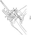
- a drill 30 is passed through one of the first and second drilling holes 6, 8 and drilled into the distal femoral condyle.
- the drill 30 is drilled into the distal femoral condyle until a stop 32 on the drill 30 abuts the body 4 and prevents the drill 30 from drilling any deeper.
- the length of the first and second drilling holes 6, 8 and the length of the drill 30 therefore controls the depth of the hole.
- the hole may be used to mount a cutting guide and/or milling spigot for resection of the femoral condyle to the desired shape for the femoral component.
- the fixed foot may contact the tibial plateau and the movable foot may contact the posterior femoral condyle.
- first and second drilling holes 6, 8 may be replaced by a single drilling hole which is pivotably mounted in the body 4.
- the angle of the single drilling hole may be adjusted to correspond to the femoral component and locked in position by a locking mechanism.
- the locking mechanism and single drilling hole may be provided with an indexing mechanism which provides discrete angles for the single drilling hole.
- the present invention has been described in reference to a knee replacement; however the invention may be adapted to be used in other joints.
- the present invention provides a drill guide which does not require the use of feeler gauges and which has a direct connection to the intramedullary rod so as to simplify alignment of the drill guide.
Landscapes
- Health & Medical Sciences (AREA)
- Surgery (AREA)
- Life Sciences & Earth Sciences (AREA)
- Orthopedic Medicine & Surgery (AREA)
- Biomedical Technology (AREA)
- Public Health (AREA)
- Veterinary Medicine (AREA)
- Engineering & Computer Science (AREA)
- Nuclear Medicine, Radiotherapy & Molecular Imaging (AREA)
- Heart & Thoracic Surgery (AREA)
- Medical Informatics (AREA)
- Molecular Biology (AREA)
- Animal Behavior & Ethology (AREA)
- General Health & Medical Sciences (AREA)
- Dentistry (AREA)
- Oral & Maxillofacial Surgery (AREA)
- Neurology (AREA)
- Surgical Instruments (AREA)
- Prostheses (AREA)
Claims (7)
- Femorale Bohrführung (2), umfassend:ein Ausrichtungsinstrument (22);einen Körper (4), der folgendes umfasst:ein Loch (6, 8), das sich zum Führen eines Bohrers dort hindurch erstreckt;einen femoralen intramedullären Stab (24);wobei das Ausrichtungsinstrument (22) einen ersten Arm (25), einen zweiten Arm (26) und einen Griff (23) umfasst, wobei der erste und der zweite Arm (25, 26) drehbar an dem Griff (23) angebracht sind, so dass der Abstand zwischen dem ersten und dem zweiten Arm (25, 26) angepasst werden kann, wobei der erste Arm (25) so funktionsfähig ist, dass das Ausrichtungsinstrument (22) mit dem Körper (4) verbunden wird, und wobei der zweite Arm (26) so funktionsfähig ist, dass das Ausrichtungsinstrument (22) mit dem femoralen intramedullären Stab (24) verbunden wird, so dass die Ausrichtung des Körpers (4) im Verhältnis zu dem femoralen intramedullären Stab (24) in der anteroposterioren Ebene und in einer transversalen Ebene fixierbar ist;dadurch gekennzeichnet, dass der Körper (4) ferner erste und zweite Befestigungslöcher (28) zur Aufnahme des Ausrichtungsinstruments (22) und zur Verwendung der Bohrführung (2) an einem linken oder rechten Knie umfasst, wobei das erste Befestigungsloch (28) zu der linken lateralen Seite des Körpers (4) angewinkelt ist, und wobei das zweite Befestigungsloch (28) zu der rechten lateralen Seite des Körpers (4) angewinkelt ist; wobei der erste Arm (25) für eine Aufnahme in jedem der Befestigungslöcher (28) gestaltet ist.
- Femorale Bohrführung (2) nach Anspruch 1, wobei ein Element des femoralen intramedullären Stabs (24) und des zweiten Arms (26) kanüliert ist, und wobei das jeweils andere Element des femoralen intramedullären Stabs (24) und des zweiten Arms (26) in dem einen Element des femoralen intramedullären Stabs (24) und des zweiten Arms (26) aufgenommen wird.
- Femorale Bohrführung (2) nach Anspruch 1 oder 2, wobei die Befestigungslöcher (28) um 7° zu der linken oder rechten lateralen Seite des Körpers (4) angewinkelt sind.
- Femorale Bohrführung (2) nach einem der Ansprüche 1 bis 3, wobei die Befestigungslöcher (28) in der vertikalen Ebene im Verhältnis zu dem Körper (4) nach unten um 5° angewinkelt sind.
- Femorale Bohrführung (2) nach Anspruch 1, wobei das Loch durch ein röhrenförmiges Element definiert ist, das drehbar im Verhältnis zu dem Körper (4) angebracht ist, so dass der Winkel des röhrenförmigen Elements im Verhältnis zu dem Körper (4) anpassbar ist.
- Femorale Bohrführung (2) nach Anspruch 1, wobei das Loch erste und zweite Löcher (6, 8) umfasst, die sich in unterschiedlichen Winkeln von 0° und 10° oder von 5° und 15° entsprechend durch den Körper (4) erstrecken.
- Femorale Bohrführung (2) nach Anspruch 1, wobei der Körper (4) ferner einen Vorsprung (10) auf einer linken lateralen Seite des Körpers (4) und einen Vorsprung (12) auf einer rechten lateralen Seite des Körpers (4) umfasst, und wobei der Abstand zwischen den Vorsprüngen (10, 12) gleich einer Breite einer femoralen Komponente ist.
Applications Claiming Priority (3)
| Application Number | Priority Date | Filing Date | Title |
|---|---|---|---|
| GB0920225A GB2475491A (en) | 2009-11-18 | 2009-11-18 | Alignment tool for a femoral drill guide |
| EP10781729.8A EP2501302B1 (de) | 2009-11-18 | 2010-11-17 | Bohrführung |
| PCT/GB2010/002117 WO2011061489A1 (en) | 2009-11-18 | 2010-11-17 | A drill guide |
Related Parent Applications (2)
| Application Number | Title | Priority Date | Filing Date |
|---|---|---|---|
| EP10781729.8A Division EP2501302B1 (de) | 2009-11-18 | 2010-11-17 | Bohrführung |
| EP10781729.8A Division-Into EP2501302B1 (de) | 2009-11-18 | 2010-11-17 | Bohrführung |
Publications (2)
| Publication Number | Publication Date |
|---|---|
| EP2896375A1 EP2896375A1 (de) | 2015-07-22 |
| EP2896375B1 true EP2896375B1 (de) | 2020-04-15 |
Family
ID=41565500
Family Applications (2)
| Application Number | Title | Priority Date | Filing Date |
|---|---|---|---|
| EP10781729.8A Active EP2501302B1 (de) | 2009-11-18 | 2010-11-17 | Bohrführung |
| EP15152599.5A Active EP2896375B1 (de) | 2009-11-18 | 2010-11-17 | Bohrführung |
Family Applications Before (1)
| Application Number | Title | Priority Date | Filing Date |
|---|---|---|---|
| EP10781729.8A Active EP2501302B1 (de) | 2009-11-18 | 2010-11-17 | Bohrführung |
Country Status (8)
| Country | Link |
|---|---|
| US (1) | US9028503B2 (de) |
| EP (2) | EP2501302B1 (de) |
| JP (1) | JP5750117B2 (de) |
| KR (1) | KR101757010B1 (de) |
| AU (1) | AU2010320719B2 (de) |
| CA (1) | CA2781006C (de) |
| GB (1) | GB2475491A (de) |
| WO (1) | WO2011061489A1 (de) |
Families Citing this family (13)
| Publication number | Priority date | Publication date | Assignee | Title |
|---|---|---|---|---|
| GB2482702A (en) | 2010-08-11 | 2012-02-15 | Biomet Uk Healthcare Ltd | Ligament balancer |
| US8672946B2 (en) | 2011-02-11 | 2014-03-18 | Biomet Manfacturing, LLC | Method and apparatus for performing knee arthroplasty |
| US9241784B2 (en) | 2011-07-08 | 2016-01-26 | Smith & Nephew, Inc. | Soft tissue reconstruction |
| US9955963B2 (en) | 2011-07-08 | 2018-05-01 | Smith & Nephew, Inc. | Soft tissue repair |
| US9662105B2 (en) | 2011-07-08 | 2017-05-30 | Smith & Nephew, Inc. | Suture passer and method |
| US9357997B2 (en) | 2011-07-08 | 2016-06-07 | Smith & Nephew, Inc. | Suture passer and method |
| US8882834B2 (en) | 2011-07-08 | 2014-11-11 | Smith & Nephew, Inc. | Soft tissue repair |
| US9907558B2 (en) | 2011-07-08 | 2018-03-06 | Smith & Nephew, Inc. | Osteotomy guide and method |
| EP2729080B1 (de) * | 2011-07-08 | 2019-02-27 | Smith & Nephew, Inc. | Orthopädische instrumente |
| GB2506616B (en) * | 2012-10-03 | 2018-12-05 | Corin Ltd | Leg alignment apparatus and method |
| KR102053600B1 (ko) * | 2017-07-25 | 2019-12-11 | 주식회사 코렌텍 | 환자 맞춤형 어깨관절 수술기구 |
| WO2021029984A1 (en) * | 2019-08-14 | 2021-02-18 | Smith & Nephew, Inc. | Instruments and methods for preparing a femur in a partial knee reconstruction |
| WO2025064874A1 (en) * | 2023-09-20 | 2025-03-27 | Paragon 28, Inc. | Right angle drill, instrumentation, system and methods of use and assembly |
Family Cites Families (35)
| Publication number | Priority date | Publication date | Assignee | Title |
|---|---|---|---|---|
| US2666430A (en) * | 1949-05-31 | 1954-01-19 | Gispert Humberto Altamirano | Hip nail aiming and guiding device |
| US2697433A (en) * | 1951-12-04 | 1954-12-21 | Max A Zehnder | Device for accurately positioning and guiding guide wires used in the nailing of thefemoral neck |
| US4566448A (en) | 1983-03-07 | 1986-01-28 | Rohr Jr William L | Ligament tensor and distal femoral resector guide |
| DE3878156T2 (de) * | 1987-10-21 | 1993-05-27 | Smith & Nephew Richards Inc | Chirurgisches instrument. |
| US5385567A (en) * | 1990-09-07 | 1995-01-31 | Goble; E. Marlowe | Sight barrel arthroscopic instrument |
| EP0613658B1 (de) * | 1993-03-05 | 2001-09-12 | Sulzer Orthopädie AG | Vorrichtung zum Bestimmen des Verlaufs von Bohrungen in Knochen |
| DE9308276U1 (de) * | 1993-06-02 | 1993-08-05 | Weber, Gerhard, 78727 Oberndorf | Vorrichtung zur ventralen Verschraubung von Dens-Frakturen mit Kompressionsschrauben |
| US5423827A (en) * | 1994-06-02 | 1995-06-13 | Intermedics Orthopedics, Inc. | Surgical jig for femoral knee prosthesis |
| IT1268313B1 (it) * | 1994-07-28 | 1997-02-27 | Orthofix Srl | Attrezzatura meccanica per il centraggio di fori ciechi per viti ossee di chiodi intramidollari |
| DE19510372C1 (de) * | 1995-03-22 | 1996-07-25 | Aesculap Ag | Bohrlehre für chirurgische Bohrwerkzeuge |
| US5776194A (en) * | 1996-04-25 | 1998-07-07 | Nuvana Medical Innovations, Llc | Intermedullary rod apparatus and methods of repairing proximal humerus fractures |
| GB9611074D0 (en) * | 1996-05-28 | 1996-07-31 | Howmedica | Surgical apparatus |
| EP1095626B1 (de) | 1999-11-01 | 2016-02-24 | Zimmer GmbH | Radiusmarknagel |
| EP1276424B1 (de) * | 2000-04-27 | 2004-12-29 | Finsbury (Development) Limited | Spanngerät zum ausführen einer knieersatzoperation |
| AT410282B (de) * | 2000-09-01 | 2003-03-25 | Ender Hans Georg | Knochennagel und setz- und zielgerät hiefür |
| ATE330565T1 (de) * | 2001-04-27 | 2006-07-15 | Zimmer Gmbh | Bohrlehere für die festlegung der achse einer femurkopfprothese |
| EP1260188B1 (de) | 2001-05-25 | 2014-09-17 | Zimmer GmbH | Oberschenkel-Marknagel zum Einbringen am Kniegelenk |
| FR2829376A1 (fr) * | 2001-09-07 | 2003-03-14 | Bertrand Bergue | Materiel de reperage de coupes femoro-tibiale |
| PT1480582E (pt) * | 2002-02-14 | 2012-10-02 | Biomet Spain Orthopaedics S L | Substituição da articulação patelo-femoral |
| DE10215358B4 (de) | 2002-04-08 | 2007-03-08 | Mathys Medizinaltechnik Ag | Bänderspannvorrichtung mit Schnittlehre |
| US20040153066A1 (en) * | 2003-02-03 | 2004-08-05 | Coon Thomas M. | Apparatus for knee surgery and method of use |
| US20040220583A1 (en) * | 2003-02-04 | 2004-11-04 | Zimmer Technology, Inc. | Instrumentation for total knee arthroplasty, and methods of performing same |
| DE10309493A1 (de) * | 2003-02-26 | 2004-09-16 | Aesculap Ag & Co. Kg | Chirurgische Positionier- und Haltevorrichtung |
| US7641659B2 (en) * | 2003-03-13 | 2010-01-05 | Zimmer Spine, Inc. | Spinal access instrument |
| ES2246438T3 (es) * | 2003-04-25 | 2006-02-16 | Zimmer Gmbh | Dispositivo para la preparacion de un condilo femoral. |
| US7481814B1 (en) * | 2003-07-28 | 2009-01-27 | Biomet Manufacturing Corporation | Method and apparatus for use of a mill or reamer |
| GB0404347D0 (en) * | 2004-02-27 | 2004-03-31 | Depuy Int Ltd | A drill guide assembly |
| WO2005084560A1 (en) * | 2004-03-01 | 2005-09-15 | Depuy International Limited | An alignment instrument for use with an intramedullary nail |
| US20060064104A1 (en) | 2004-09-09 | 2006-03-23 | Kana Richard J | Translating surgical mount |
| DE102004063977A1 (de) * | 2004-10-19 | 2006-06-22 | Mathys Ag Bettlach | Bänderspannvorrichtung, Schnittlehre und Verfahren zur Osteotomie |
| GB2423021A (en) * | 2005-02-15 | 2006-08-16 | Biomet Uk Ltd | A surgical guide jig with an expanding spherical joint |
| US20070100346A1 (en) * | 2005-10-27 | 2007-05-03 | Wyss Joseph G | Support for locating instrument guides |
| US8685034B2 (en) * | 2006-08-10 | 2014-04-01 | Stryker Trauma Gmbh | Distal targeting device |
| CA2669644C (en) * | 2006-11-21 | 2015-06-16 | Smith & Nephew, Inc. | Variable angle drill guide |
| US8771283B2 (en) * | 2007-12-17 | 2014-07-08 | Wright Medical Technology, Inc. | Guide assembly for intramedullary fixation and method of using the same |
-
2009
- 2009-11-18 GB GB0920225A patent/GB2475491A/en not_active Withdrawn
-
2010
- 2010-11-17 WO PCT/GB2010/002117 patent/WO2011061489A1/en not_active Ceased
- 2010-11-17 KR KR1020127015320A patent/KR101757010B1/ko not_active Expired - Fee Related
- 2010-11-17 JP JP2012539404A patent/JP5750117B2/ja active Active
- 2010-11-17 EP EP10781729.8A patent/EP2501302B1/de active Active
- 2010-11-17 EP EP15152599.5A patent/EP2896375B1/de active Active
- 2010-11-17 AU AU2010320719A patent/AU2010320719B2/en active Active
- 2010-11-17 CA CA2781006A patent/CA2781006C/en active Active
- 2010-11-17 US US13/510,480 patent/US9028503B2/en active Active
Non-Patent Citations (1)
| Title |
|---|
| None * |
Also Published As
| Publication number | Publication date |
|---|---|
| KR101757010B1 (ko) | 2017-07-11 |
| CA2781006C (en) | 2018-07-24 |
| WO2011061489A1 (en) | 2011-05-26 |
| JP2013511316A (ja) | 2013-04-04 |
| GB0920225D0 (en) | 2010-01-06 |
| US9028503B2 (en) | 2015-05-12 |
| EP2896375A1 (de) | 2015-07-22 |
| US20120323249A1 (en) | 2012-12-20 |
| AU2010320719A1 (en) | 2012-06-07 |
| CA2781006A1 (en) | 2011-05-26 |
| AU2010320719B2 (en) | 2015-01-22 |
| EP2501302B1 (de) | 2015-11-11 |
| JP5750117B2 (ja) | 2015-07-15 |
| GB2475491A (en) | 2011-05-25 |
| EP2501302A1 (de) | 2012-09-26 |
| KR20120132468A (ko) | 2012-12-05 |
Similar Documents
| Publication | Publication Date | Title |
|---|---|---|
| EP2896375B1 (de) | Bohrführung | |
| US20250090180A1 (en) | Resection guides, sweeping reamers, and methods for use in total ankle replacement | |
| EP1095624B1 (de) | Fräsausrüstung zur Verwendung bei einer totalen Kniegelenkrekonstruktion | |
| EP2001373B1 (de) | Orthopädisches schneidführungsinstrument | |
| US6033410A (en) | Orthopaedic instrumentation | |
| EP2568890B1 (de) | Grössenbestimmungsführung für oberschenkel | |
| EP2775942B1 (de) | Knochenbemessungsführung | |
| EP2166969B1 (de) | Universelle positionierungsvorrichtung für orthopädische chirurgie | |
| US7621920B2 (en) | Adjustable cut guide | |
| EP2568889B1 (de) | Chirurgisches instrument | |
| WO1997030640A9 (en) | Distal femoral cutting guide apparatus | |
| WO1997030640A1 (en) | Distal femoral cutting guide apparatus | |
| EP3813692B1 (de) | Chirurgisches kit zur resektion des oberschenkelhalses während hüftoperation | |
| US8043294B2 (en) | Reference mark adjustment mechanism for a femoral caliper and method of using the same | |
| EP1833386B1 (de) | Bohrerführungsanordnung | |
| AU2014268275A1 (en) | A Drill Guide | |
| US20250387126A1 (en) | Resection Guide And Flex Plate To Alter Distal Femoral Flexion | |
| EP3086719B1 (de) | Chirurgisches instrument |
Legal Events
| Date | Code | Title | Description |
|---|---|---|---|
| PUAI | Public reference made under article 153(3) epc to a published international application that has entered the european phase |
Free format text: ORIGINAL CODE: 0009012 |
|
| 17P | Request for examination filed |
Effective date: 20150127 |
|
| AC | Divisional application: reference to earlier application |
Ref document number: 2501302 Country of ref document: EP Kind code of ref document: P |
|
| AK | Designated contracting states |
Kind code of ref document: A1 Designated state(s): AL AT BE BG CH CY CZ DE DK EE ES FI FR GB GR HR HU IE IS IT LI LT LU LV MC MK MT NL NO PL PT RO RS SE SI SK SM TR |
|
| 17P | Request for examination filed |
Effective date: 20160121 |
|
| RBV | Designated contracting states (corrected) |
Designated state(s): AL AT BE BG CH CY CZ DE DK EE ES FI FR GB GR HR HU IE IS IT LI LT LU LV MC MK MT NL NO PL PT RO RS SE SI SK SM TR |
|
| 17Q | First examination report despatched |
Effective date: 20160523 |
|
| STAA | Information on the status of an ep patent application or granted ep patent |
Free format text: STATUS: EXAMINATION IS IN PROGRESS |
|
| GRAP | Despatch of communication of intention to grant a patent |
Free format text: ORIGINAL CODE: EPIDOSNIGR1 |
|
| STAA | Information on the status of an ep patent application or granted ep patent |
Free format text: STATUS: GRANT OF PATENT IS INTENDED |
|
| RAP1 | Party data changed (applicant data changed or rights of an application transferred) |
Owner name: MURRAY, DAVID WYCLIFFE Owner name: HUNSLEY, COLIN Owner name: OXFORD JOINT ANALYSIS LTD. Owner name: BIOMET UK LIMITED |
|
| INTG | Intention to grant announced |
Effective date: 20191029 |
|
| RAP1 | Party data changed (applicant data changed or rights of an application transferred) |
Owner name: COLIN HUNSLEY, ACTING AS EXECUTOR FOR THE ESTATE O Owner name: BIOMET UK LIMITED Owner name: OXFORD JOINT ANALYSIS LTD. Owner name: MURRAY, DAVID WYCLIFFE |
|
| GRAS | Grant fee paid |
Free format text: ORIGINAL CODE: EPIDOSNIGR3 |
|
| GRAA | (expected) grant |
Free format text: ORIGINAL CODE: 0009210 |
|
| STAA | Information on the status of an ep patent application or granted ep patent |
Free format text: STATUS: THE PATENT HAS BEEN GRANTED |
|
| AC | Divisional application: reference to earlier application |
Ref document number: 2501302 Country of ref document: EP Kind code of ref document: P |
|
| AK | Designated contracting states |
Kind code of ref document: B1 Designated state(s): AL AT BE BG CH CY CZ DE DK EE ES FI FR GB GR HR HU IE IS IT LI LT LU LV MC MK MT NL NO PL PT RO RS SE SI SK SM TR |
|
| REG | Reference to a national code |
Ref country code: CH Ref legal event code: EP |
|
| REG | Reference to a national code |
Ref country code: DE Ref legal event code: R096 Ref document number: 602010063961 Country of ref document: DE |
|
| REG | Reference to a national code |
Ref country code: IE Ref legal event code: FG4D |
|
| REG | Reference to a national code |
Ref country code: AT Ref legal event code: REF Ref document number: 1256378 Country of ref document: AT Kind code of ref document: T Effective date: 20200515 |
|
| REG | Reference to a national code |
Ref country code: CH Ref legal event code: NV Representative=s name: MICHELI AND CIE SA, CH |
|
| REG | Reference to a national code |
Ref country code: NL Ref legal event code: MP Effective date: 20200415 |
|
| REG | Reference to a national code |
Ref country code: LT Ref legal event code: MG4D |
|
| REG | Reference to a national code |
Ref country code: DE Ref legal event code: R082 Ref document number: 602010063961 Country of ref document: DE Representative=s name: VENNER SHIPLEY GERMANY LLP, DE Ref country code: DE Ref legal event code: R082 Ref document number: 602010063961 Country of ref document: DE Representative=s name: VENNER SHIPLEY LLP, DE |
|
| PG25 | Lapsed in a contracting state [announced via postgrant information from national office to epo] |
Ref country code: SE Free format text: LAPSE BECAUSE OF FAILURE TO SUBMIT A TRANSLATION OF THE DESCRIPTION OR TO PAY THE FEE WITHIN THE PRESCRIBED TIME-LIMIT Effective date: 20200415 Ref country code: FI Free format text: LAPSE BECAUSE OF FAILURE TO SUBMIT A TRANSLATION OF THE DESCRIPTION OR TO PAY THE FEE WITHIN THE PRESCRIBED TIME-LIMIT Effective date: 20200415 Ref country code: IS Free format text: LAPSE BECAUSE OF FAILURE TO SUBMIT A TRANSLATION OF THE DESCRIPTION OR TO PAY THE FEE WITHIN THE PRESCRIBED TIME-LIMIT Effective date: 20200815 Ref country code: NO Free format text: LAPSE BECAUSE OF FAILURE TO SUBMIT A TRANSLATION OF THE DESCRIPTION OR TO PAY THE FEE WITHIN THE PRESCRIBED TIME-LIMIT Effective date: 20200715 Ref country code: GR Free format text: LAPSE BECAUSE OF FAILURE TO SUBMIT A TRANSLATION OF THE DESCRIPTION OR TO PAY THE FEE WITHIN THE PRESCRIBED TIME-LIMIT Effective date: 20200716 Ref country code: LT Free format text: LAPSE BECAUSE OF FAILURE TO SUBMIT A TRANSLATION OF THE DESCRIPTION OR TO PAY THE FEE WITHIN THE PRESCRIBED TIME-LIMIT Effective date: 20200415 Ref country code: PT Free format text: LAPSE BECAUSE OF FAILURE TO SUBMIT A TRANSLATION OF THE DESCRIPTION OR TO PAY THE FEE WITHIN THE PRESCRIBED TIME-LIMIT Effective date: 20200817 Ref country code: NL Free format text: LAPSE BECAUSE OF FAILURE TO SUBMIT A TRANSLATION OF THE DESCRIPTION OR TO PAY THE FEE WITHIN THE PRESCRIBED TIME-LIMIT Effective date: 20200415 |
|
| REG | Reference to a national code |
Ref country code: AT Ref legal event code: MK05 Ref document number: 1256378 Country of ref document: AT Kind code of ref document: T Effective date: 20200415 |
|
| PG25 | Lapsed in a contracting state [announced via postgrant information from national office to epo] |
Ref country code: LV Free format text: LAPSE BECAUSE OF FAILURE TO SUBMIT A TRANSLATION OF THE DESCRIPTION OR TO PAY THE FEE WITHIN THE PRESCRIBED TIME-LIMIT Effective date: 20200415 Ref country code: BG Free format text: LAPSE BECAUSE OF FAILURE TO SUBMIT A TRANSLATION OF THE DESCRIPTION OR TO PAY THE FEE WITHIN THE PRESCRIBED TIME-LIMIT Effective date: 20200715 Ref country code: RS Free format text: LAPSE BECAUSE OF FAILURE TO SUBMIT A TRANSLATION OF THE DESCRIPTION OR TO PAY THE FEE WITHIN THE PRESCRIBED TIME-LIMIT Effective date: 20200415 Ref country code: HR Free format text: LAPSE BECAUSE OF FAILURE TO SUBMIT A TRANSLATION OF THE DESCRIPTION OR TO PAY THE FEE WITHIN THE PRESCRIBED TIME-LIMIT Effective date: 20200415 |
|
| PG25 | Lapsed in a contracting state [announced via postgrant information from national office to epo] |
Ref country code: AL Free format text: LAPSE BECAUSE OF FAILURE TO SUBMIT A TRANSLATION OF THE DESCRIPTION OR TO PAY THE FEE WITHIN THE PRESCRIBED TIME-LIMIT Effective date: 20200415 |
|
| REG | Reference to a national code |
Ref country code: DE Ref legal event code: R097 Ref document number: 602010063961 Country of ref document: DE |
|
| PG25 | Lapsed in a contracting state [announced via postgrant information from national office to epo] |
Ref country code: CZ Free format text: LAPSE BECAUSE OF FAILURE TO SUBMIT A TRANSLATION OF THE DESCRIPTION OR TO PAY THE FEE WITHIN THE PRESCRIBED TIME-LIMIT Effective date: 20200415 Ref country code: RO Free format text: LAPSE BECAUSE OF FAILURE TO SUBMIT A TRANSLATION OF THE DESCRIPTION OR TO PAY THE FEE WITHIN THE PRESCRIBED TIME-LIMIT Effective date: 20200415 Ref country code: EE Free format text: LAPSE BECAUSE OF FAILURE TO SUBMIT A TRANSLATION OF THE DESCRIPTION OR TO PAY THE FEE WITHIN THE PRESCRIBED TIME-LIMIT Effective date: 20200415 Ref country code: DK Free format text: LAPSE BECAUSE OF FAILURE TO SUBMIT A TRANSLATION OF THE DESCRIPTION OR TO PAY THE FEE WITHIN THE PRESCRIBED TIME-LIMIT Effective date: 20200415 Ref country code: AT Free format text: LAPSE BECAUSE OF FAILURE TO SUBMIT A TRANSLATION OF THE DESCRIPTION OR TO PAY THE FEE WITHIN THE PRESCRIBED TIME-LIMIT Effective date: 20200415 Ref country code: SM Free format text: LAPSE BECAUSE OF FAILURE TO SUBMIT A TRANSLATION OF THE DESCRIPTION OR TO PAY THE FEE WITHIN THE PRESCRIBED TIME-LIMIT Effective date: 20200415 Ref country code: IT Free format text: LAPSE BECAUSE OF FAILURE TO SUBMIT A TRANSLATION OF THE DESCRIPTION OR TO PAY THE FEE WITHIN THE PRESCRIBED TIME-LIMIT Effective date: 20200415 Ref country code: ES Free format text: LAPSE BECAUSE OF FAILURE TO SUBMIT A TRANSLATION OF THE DESCRIPTION OR TO PAY THE FEE WITHIN THE PRESCRIBED TIME-LIMIT Effective date: 20200415 |
|
| PLBE | No opposition filed within time limit |
Free format text: ORIGINAL CODE: 0009261 |
|
| STAA | Information on the status of an ep patent application or granted ep patent |
Free format text: STATUS: NO OPPOSITION FILED WITHIN TIME LIMIT |
|
| PG25 | Lapsed in a contracting state [announced via postgrant information from national office to epo] |
Ref country code: SK Free format text: LAPSE BECAUSE OF FAILURE TO SUBMIT A TRANSLATION OF THE DESCRIPTION OR TO PAY THE FEE WITHIN THE PRESCRIBED TIME-LIMIT Effective date: 20200415 Ref country code: PL Free format text: LAPSE BECAUSE OF FAILURE TO SUBMIT A TRANSLATION OF THE DESCRIPTION OR TO PAY THE FEE WITHIN THE PRESCRIBED TIME-LIMIT Effective date: 20200415 |
|
| 26N | No opposition filed |
Effective date: 20210118 |
|
| PG25 | Lapsed in a contracting state [announced via postgrant information from national office to epo] |
Ref country code: SI Free format text: LAPSE BECAUSE OF FAILURE TO SUBMIT A TRANSLATION OF THE DESCRIPTION OR TO PAY THE FEE WITHIN THE PRESCRIBED TIME-LIMIT Effective date: 20200415 |
|
| PG25 | Lapsed in a contracting state [announced via postgrant information from national office to epo] |
Ref country code: MC Free format text: LAPSE BECAUSE OF FAILURE TO SUBMIT A TRANSLATION OF THE DESCRIPTION OR TO PAY THE FEE WITHIN THE PRESCRIBED TIME-LIMIT Effective date: 20200415 |
|
| PG25 | Lapsed in a contracting state [announced via postgrant information from national office to epo] |
Ref country code: LU Free format text: LAPSE BECAUSE OF NON-PAYMENT OF DUE FEES Effective date: 20201117 |
|
| REG | Reference to a national code |
Ref country code: BE Ref legal event code: MM Effective date: 20201130 |
|
| PG25 | Lapsed in a contracting state [announced via postgrant information from national office to epo] |
Ref country code: IE Free format text: LAPSE BECAUSE OF NON-PAYMENT OF DUE FEES Effective date: 20201117 |
|
| PG25 | Lapsed in a contracting state [announced via postgrant information from national office to epo] |
Ref country code: TR Free format text: LAPSE BECAUSE OF FAILURE TO SUBMIT A TRANSLATION OF THE DESCRIPTION OR TO PAY THE FEE WITHIN THE PRESCRIBED TIME-LIMIT Effective date: 20200415 Ref country code: MT Free format text: LAPSE BECAUSE OF FAILURE TO SUBMIT A TRANSLATION OF THE DESCRIPTION OR TO PAY THE FEE WITHIN THE PRESCRIBED TIME-LIMIT Effective date: 20200415 Ref country code: CY Free format text: LAPSE BECAUSE OF FAILURE TO SUBMIT A TRANSLATION OF THE DESCRIPTION OR TO PAY THE FEE WITHIN THE PRESCRIBED TIME-LIMIT Effective date: 20200415 |
|
| PG25 | Lapsed in a contracting state [announced via postgrant information from national office to epo] |
Ref country code: MK Free format text: LAPSE BECAUSE OF FAILURE TO SUBMIT A TRANSLATION OF THE DESCRIPTION OR TO PAY THE FEE WITHIN THE PRESCRIBED TIME-LIMIT Effective date: 20200415 |
|
| PG25 | Lapsed in a contracting state [announced via postgrant information from national office to epo] |
Ref country code: BE Free format text: LAPSE BECAUSE OF NON-PAYMENT OF DUE FEES Effective date: 20201130 |
|
| P01 | Opt-out of the competence of the unified patent court (upc) registered |
Effective date: 20230526 |
|
| REG | Reference to a national code |
Ref country code: CH Ref legal event code: U11 Free format text: ST27 STATUS EVENT CODE: U-0-0-U10-U11 (AS PROVIDED BY THE NATIONAL OFFICE) Effective date: 20251201 |
|
| PGFP | Annual fee paid to national office [announced via postgrant information from national office to epo] |
Ref country code: DE Payment date: 20251021 Year of fee payment: 16 |
|
| PGFP | Annual fee paid to national office [announced via postgrant information from national office to epo] |
Ref country code: GB Payment date: 20251114 Year of fee payment: 16 |
|
| PGFP | Annual fee paid to national office [announced via postgrant information from national office to epo] |
Ref country code: FR Payment date: 20251112 Year of fee payment: 16 |
|
| PGFP | Annual fee paid to national office [announced via postgrant information from national office to epo] |
Ref country code: CH Payment date: 20251201 Year of fee payment: 16 |