EP3086719B1 - Chirurgisches instrument - Google Patents
Chirurgisches instrument Download PDFInfo
- Publication number
- EP3086719B1 EP3086719B1 EP14820922.4A EP14820922A EP3086719B1 EP 3086719 B1 EP3086719 B1 EP 3086719B1 EP 14820922 A EP14820922 A EP 14820922A EP 3086719 B1 EP3086719 B1 EP 3086719B1
- Authority
- EP
- European Patent Office
- Prior art keywords
- arm
- elongate member
- head assembly
- inferior surface
- mount
- Prior art date
- Legal status (The legal status is an assumption and is not a legal conclusion. Google has not performed a legal analysis and makes no representation as to the accuracy of the status listed.)
- Not-in-force
Links
- 238000001356 surgical procedure Methods 0.000 claims description 10
- 210000000988 bone and bone Anatomy 0.000 claims description 5
- 230000001154 acute effect Effects 0.000 claims description 3
- 210000002303 tibia Anatomy 0.000 description 8
- 238000000034 method Methods 0.000 description 3
- 241001422033 Thestylus Species 0.000 description 1
- 230000001419 dependent effect Effects 0.000 description 1
- 238000000605 extraction Methods 0.000 description 1
- 239000007943 implant Substances 0.000 description 1
- 210000003127 knee Anatomy 0.000 description 1
- 210000000629 knee joint Anatomy 0.000 description 1
- 238000013150 knee replacement Methods 0.000 description 1
- 210000002414 leg Anatomy 0.000 description 1
- 210000001699 lower leg Anatomy 0.000 description 1
- 239000000463 material Substances 0.000 description 1
- 238000012829 orthopaedic surgery Methods 0.000 description 1
- 229920000642 polymer Polymers 0.000 description 1
- 238000002271 resection Methods 0.000 description 1
- 238000000926 separation method Methods 0.000 description 1
- 238000003786 synthesis reaction Methods 0.000 description 1
Images


Classifications
-
- A—HUMAN NECESSITIES
- A61—MEDICAL OR VETERINARY SCIENCE; HYGIENE
- A61B—DIAGNOSIS; SURGERY; IDENTIFICATION
- A61B17/00—Surgical instruments, devices or methods
- A61B17/14—Surgical saws
- A61B17/15—Guides therefor
- A61B17/154—Guides therefor for preparing bone for knee prosthesis
- A61B17/157—Cutting tibia
Definitions
- the present invention relates to surgical instruments and in particular to a jig assembly used in orthopaedic surgery.
- Knee replacement surgery is complex and requires the bone surfaces to be prepared.
- femoral and tibial resectioning in which a saw or other cutting tool is used to prepare bone surfaces to receive surgical implants, is required.
- a number of tools and instruments can be used to assist the surgeon in carrying out the procedure appropriately.
- a cutting block is usually used in order to guide the saw during the resection procedure.
- the cutting block is mounted and secured at the appropriate position on the bone surface.
- the correct positioning of the cutting block may be assisted by means of a jig and/or other alignment and support tools.
- a tibial jig can be used in order to align a cutting block with respect to the longitudinal axis of the tibia.
- the tibial jig comprises a rod which can be in two parts to accommodate different tibia lengths.
- An appropriate cutting block is mounted on the rod, aligned at the proximal end of the tibia, and then secured in place by means of pins.
- the cutting block defines an upper surface for guiding the cutting tool and may have a slot which can also be used as a cutting tool guiding surface.
- the slot can also be used as a means to attach other instruments such as a condylar stylus, or an alignment and adjustment tool.
- the jig may also include a mechanism for adjusting the flexion/extension slope of the cutting tool guiding surface.
- tibial jig is disclosed in EP-A-2014/0324054 .
- This includes a spiked head assembly for attachment to a tibial jig.
- the assembly includes a body and an arm.
- the arm is not spaced such that the arm and an inferior surface of the body define an access space for a surgical procedure.
- Another tibial jig is the one designed for use with the Attune® knee prosthetic system from De Puy Synthes.
- the spiked jig that includes a rod which is aligned parallel to the tibia in the same way as the jig referred to above, but also includes a head which extends perpendicularly to the rod at a position that extends beyond the proximal end of the tibia at the knee joint.
- the head is mounted onto the rod by means of a mounting rod.
- the head includes a number of downwardly extending spikes which can be inserted into the tibia at the tibial eminence. One spike is longer than the other.
- the cutting block is supported by the rod and mounted at an intermediate location on the tibia.
- the cutting block is therefore mounted partially along the rod rather than at the end as with the jig described above.
- a spiked head assembly for attachment to a tibial jig for use during an orthopaedic surgical procedure as defined in claim 1.
- This assembly can be mounted onto a standard tibial jig at the end of the jig that is aligned with the cutting block.
- the at least one arm is displaced or spaced apart from the plane which includes the central longitudinal axis of the elongate member which carries the at least one securing spike, an access space is defined between the at least one arm and the inferior surface of the elongate member thus allowing access to the slot in the cutting block.
- This means that the spiked head assembly does not need to be removed when access to the cutting block is required and additional tools such as a long leg alignment guide can be used.
- the at least one arm and a side edge of the elongate member may be configured to subtend an acute angle.
- This provides an assembly body which has a Z-shaped side profile. This enables the elongate member to have an increased length, and therefore increased strength and resistance to impact, while still enabling the at least one securing spike to be fixated in the tibial eminence. This is significant in view of the fact that the assembly will be required to be hammered in place when in use.
- the body may comprise a first arm and a second arm, the first arm and the second arm both extending from the elongate member in the same direction substantially perpendicularly to the inferior surface, the first and second arms being displaced laterally from each other, and from the plane including the central longitudinal axis and extending substantially perpendicularly to the inferior surface, in opposing directions such that the access space is defined by the first arm, the second arm and the inferior surface.
- the body may include a crosspiece connected between the first and second arms.
- the crosspiece may be U-shaped or T-shaped.
- the mount may comprise a body having a pair of grooves provided on opposite sides of the body and arranged to receive respective terminating ends of the first and second arms.
- the mount body may comprise a pair of hingedly connected body portions which, when in a closed position, are configured to clamp the mount to the tibial jig.
- the mount body may have an internal surface contour configured to match the contour of the outer surface of the tibial jig.
- This provides a mount that enables the assembly to be detachably connected to the jig.
- the mount can be integral with the jig.
- the elongate member may comprise a first part and a second part, the first part being attached to the at least one arm and the second part including the at least one securing spike and being detachably connected to the first part for slidable movement relative to the first part along the central longitudinal axis.
- the first part may include a grooved recess and the second part may include a lipped portion, the lipped portion being arranged to be receivable into the grooved recess for cooperation therewith, and the second part may include a securing means for securing the first part to the second part when the lipped portion is received into the grooved recess.
- the securing means may be a rotatable knob that translates a bolt into and out of engagement with the floor of the grooved recess to secure the first part to the second part.
- the knob may include a retaining pin to prevent the knob from being removed from the second part.
- the elongate member may have a reduced profile at the second end.
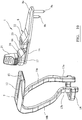
- a spiked head assembly 100 for a tibial jig 101 comprises a main body 1 and a mount 25.
- the main body 1 comprises an elongate member 2 having a central longitudinal axis X, a first end 3, and a second end 4, a superior surface 5 and an inferior surface 6.
- the elongate member 2 has side edges 28a, 28b.
- the main body 1 has a pair of arms, comprising a first arm 10a and a second arm 10b, attached to, and extending from, the first end 3 of the elongate member 2.
- the first arm 10a, and the second arm 10b extend from the first end 3 at a respective side edge 28a, 28b of the elongate member 2, such that the first arm 10a, and the second arm 10b are spaced apart from each other.
- the first end 3 of the elongate member 2 being proximal to the point of attachment between the elongate member 2 and the pair of arms 10a, 10b, is a proximal end
- the second end 4 is a distal end of the elongate member 2, being the end away from this point of attachment between the elongate member and the pair of arms 10a, 10b.
- the elongate member 2 comprises a first part 7 and a second part 8, the second part 8 being slidable with respect to the first part 7 as indicated by the double-headed arrow in Figure 2 .
- the first part 7 includes the first end 3 of the elongate member 2 and the second part 8 includes the second end 4 of the elongate member 2. Extending substantially perpendicularly from the inferior surface 6 towards the second end 4 are a pair of spiked pins 9a, 9b. One of the pins 9a is longer than the other 9b.
- the inferior surface 6 has a stepped profile at the point where the first part 7 ends.
- Each of the first and second arms 10a, 10b subtend an acute angle ⁇ to the respective side edges 28a, 28b of the elongate member 2, but extend in a direction substantially perpendicularly to the inferior surface 6 as indicated by the arrow Y in Figures 1 and 5 .
- Each of the first and second arms 10a, 10b therefore present a Z-shaped profile as viewed from the side - see, for example, Figure 6 .
- the first and second arms 10a, 10b follow a curved or bowed profile as viewed from the ends of the assembly 1, as can be seen in Figure 5 .
- Each of the first and second arms 10a, 10b terminates in a straight end segment 13a, 13b.
- a U-shaped crosspiece 14 extends perpendicular to, and between, the end segments 13a, 13b.
- the first and second arms 10a, 10b are spaced apart, laterally of each other, and of this transverse plane A - one arm 10a, 10b on either side of the plane A. This is illustrated in Figure 5 .
- the first and second arms 10a, 10b and the inferior surface 6 define an access space 11 for the assembly 1.
- the access space 11 therefore comprises the space bounded by the inferior surface 6, extending from the first end 3 of the elongate member 2, and the first and second arms 10a, 10b.
- the access space 11 is accessible through the space defined by the spaced apart first and second arms 10a, 10b.
- the first part 7 of the elongate member 2 includes a longitudinal U-shaped recess 12 in the superior surface 5.
- the U-shaped recess 12 has an internal groove 15 around the perimeter of the U-shaped recess 12.
- the second part 8 of the elongate member 2 includes a tongue portion 8a which includes the second end 4 and a U-shaped rear portion 16 which has a lip 17 extending around the perimeter of the U-shaped rear portion 16.
- the U-shaped rear portion 16 is dimensioned so as to cooperate with the U-shaped recess 12 in the first part 7 so that the lip 17 can be received into the groove 15 in the U-shaped recess 12.
- first part 7 and the second part 8 can be connected together and the second part 8 is able to slide relative to the first part 7 along the central longitudinal axis X of the elongate member 2.
- the tongue portion 8a has a reduced height profile at the second end 4.
- the U-shaped rear portion 16 has a raised region 18 with a threaded cylindrical aperture 19 into which a threaded bolt 20 can be received.
- a knob 21 attached to the threaded bolt 20 can be used to manually turn the threaded bolt 20 when engaged in the threaded cylindrical aperture 19 to translate the bolt 20 within the cylindrical aperture 19 so that the bolt 21 can engage the floor of the U-shaped recess 12 so as to lock the second part 8 in position relative to the first part 7 of the elongate member 2.
- By turning the bolt 21 in the opposite direction the bolt will disengage from the floor of the U-shaped recess 12 to allow the second part to be slidable moved relative to the first part 7 of the elongate member 2 again.
- a retaining pin (not shown) is provided to prevent the knob 21 from being removed from the second part 8.
- the second part 8 also includes a raised section 22 with a second circular aperture 23 provided therein.
- the second circular aperture 23 can be used to receive an impaction/ extraction tool (not shown) as will be described in further detail below.
- the mount 25 mounts the assembly 100 to the tibial jig 101.
- the tibial jig is illustrated in Figure 3 and comprises an elongate tibial jig body 102 and a cutting block 103.
- the mount 25 comprises a body formed from two hingedly connected body portions 25a, 25b.
- Each of the body portions 25a, 25b has a groove 26a, 26b running lengthways along one side of the respective body portion 25a, 25b and a curved recesses 27a, 27b on the opposite side of the respective body portion 25a, 25b.
- the curved recesses 27a, 27b define a matching internal surface contour in which the elongate tibial jig body 102 can be received.
- the body portions 25a, 25b clamp around the elongate jig body 102 so as to secure the mount 25 to the tibial jig body 102.
- the matching surface contour can be selected depending upon the profile of the tibial jig body 102 as long as it enables the mount 25 to be clamped around the tibial jig body 102.
- the grooves 26a, 26b are aligned substantially parallel with each other on opposite sides of the mount 25 as shown, for example, in Figures 1 , 2 and 3 .
- the body portions 25a, 25b are in the closed position and the straight end segments 13a, 13b of the arms 10a, 10b are received into respective grooves 26a, 26b as illustrated in Figures 2 and 3 .
- the U-shaped crosspiece 14 encloses the mount 25 at the hinged connection between the body portions 25a, 25b thus serving to keep the mount 25 in the closed position.
- the crosspiece can be T-shaped.
- the mount 25 is attached to the tibial jig body 102 as described above.
- the position of the mount 25 along the length of the tibial jig body 102 can be selected dependent upon the required bone section.
- the tibial jig body 102 is secured to a patient's lower leg (not shown) in the usual way.
- the main body 1 is then attached to the mount 25 by inserting the straight end segments 13a. 13b into the respective grooves 26a, 26b. In this way, the arms 10a, 10b are spaced apart, laterally of the longitudinal axis of the tibial jig body 102.
- the elongate member 2 can then be adjusted by sliding the first part 7 relative to the second part 8 so as to adjust the position of the spiked pins 9a, 9b as required.
- the spiked pins 9a, 9b are hammered into position in accordance with known surgical techniques.
- tibial jig 101 is provided with a cutting tool slope adjustment mechanism 104, as shown in Figure 3 , then this can be manipulated to select the correct slope for the cutting tool.
- the access space 11 is defined by the inferior surface 6 of the elongate body 2 and the first and second arms 10a, 10b, with access to the access space 11 being available through the separation between the spaced apart first and second arms 10a, 10b.
- the access space 11 is then available for a surgeon to access the cutting block 103 for use with any required tools to carry out the necessary alignments as is well known in the art.
- a condyle stylus can be mounted on the cutting block 103. Because of the reduced profile of the second end 4 of the elongate member 2, the condyle stylus can pivoted between condyles without being obstructed by the elongate member 2.
- the assembly 100 can be removed by removing the body 2 from the mount 25 and then unclamping the mount 25 from the tibial jig body 102.
- the tibia can then be resected in accordance with known surgical techniques.
- the assembly 100 can be made of medical grade stainless and/or medical grade polymers as required. Other suitable materials may also be used.
- only a single arm 10a, 10b could be provided on the elongate member 2 with the access space 11 being defined by the arm 10a, 10b and the inferior surface 6.
Landscapes
- Health & Medical Sciences (AREA)
- Surgery (AREA)
- Life Sciences & Earth Sciences (AREA)
- Biomedical Technology (AREA)
- Medical Informatics (AREA)
- Oral & Maxillofacial Surgery (AREA)
- Nuclear Medicine, Radiotherapy & Molecular Imaging (AREA)
- Transplantation (AREA)
- Physical Education & Sports Medicine (AREA)
- Engineering & Computer Science (AREA)
- Orthopedic Medicine & Surgery (AREA)
- Heart & Thoracic Surgery (AREA)
- Dentistry (AREA)
- Molecular Biology (AREA)
- Animal Behavior & Ethology (AREA)
- General Health & Medical Sciences (AREA)
- Public Health (AREA)
- Veterinary Medicine (AREA)
- Prostheses (AREA)
- Surgical Instruments (AREA)
Claims (9)
- Stachelkopfanordnung (100) für die Befestigung an einer Tibiaspannvorrichtung (1010) für die Verwendung während eines orthopädischen chirurgischen Verfahrens, wobei die Anordnung umfasst:(a) einen Körper (1), der umfasst: ein längliches Element (2) mit einer Längsmittelachse (X), einem ersten Ende (3) und einem zweiten Ende (4), oberen (5) und unteren (6) Flächen und wenigstens einem Befestigungsstachel (9a, 9b), der auf der unteren Fläche in Richtung des zweiten Endes des länglichen Elements bereitgestellt ist und aufgebaut ist, um mit einer Knochenmasse einzugreifen; und wenigstens einen Arm (10a, 10b), der sich von dem länglichen Element in eine Richtung senkrecht zu der unteren Fläche erstreckt; und(b) eine Halterung (25) auf dem wenigstens einen Arm, die aufgebaut ist, um die Anordnung an der Tibiaspannvorrichtung zu befestigen,dadurch gekennzeichnet, dass der wenigstens eine Arm von einer Ebene (A), die die Längsmittelachse umfasst und sich im Wesentlichen senkrecht zu der unteren Oberfläche erstreckt, beabstandet ist, so dass der wenigstens eine Arm und die untere Oberfläche einen Zugangsraum (11) für das chirurgische Verfahren definieren.
- Stachelkopfanordnung (100) nach Anspruch 1, wobei der wenigstens eine Arm (10a, 10b) und ein Seitenrand (28a, 28b) des länglichen Elements (2) derart aufgebaut sind, dass sie sich in einem spitzen Winkel schneiden.
- Stachelkopfanordnung (100) nach Anspruch 1 oder Anspruch 2, wobei der Körper (1) einen ersten Arm (10a) und einen zweiten Arm (10b) umfasst, wobei der erste Arm und der zweite Arm sich beide von dem länglichen Element (2) in die gleiche Richtung im Wesentlichen senkrecht zu der unteren Oberfläche (6) erstrecken, wobei die ersten und zweiten Arme seitlich voneinander und von der Ebene (A), die die Längsmittelachse (X) enthält und die sich im Wesentlichen senkrecht zu der unteren Fläche erstreckt, beabstandet sind, so dass der Zugangsraum (11) durch den ersten Arm, den zweiten Arm und die untere Fläche definiert ist.
- Stachelkopfanordnung (100) nach Anspruch 3, wobei der Körper (1) ein Querstück (14) umfasst, das zwischen den ersten (10a) und zweiten (110b) Armen verbindet.
- Stachelkopfanordnung (100) nach Anspruch 3 oder Anspruch 4, wobei die Halterung (25) einen Körper (25a, 25b) mit einem Paar von Nuten (26a, 26b) umfasst, die auf entgegengesetzten Seiten des Körpers bereitgestellt sind und eingerichtet sind, um jeweilige Abschlussenden der ersten (10a) und zweiten (10b) Arme aufzunehmen.
- Stachelkopfanordnung (100) nach Anspruch 5, wobei der Halterungskörper ein Paar von gelenkig verbundenen Körperabschnitten (25a, 25b) umfasst, die, wenn sie in einer geschlossenen Position sind, aufgebaut sind, die Halterung an die Tibiaspannvorrichtung zu spannen.
- Stachelkopfanordnung (100) nach einem der vorhergehenden Ansprüche, wobei das längliche Element (2) einen ersten Teil (7) und einen zweiten Teil (8) umfasst, wobei der erste Teil an dem wenigstens einen Arm (10a, 10b) befestigt ist und der zweite Teil den wenigstens einen Befestigungsstachel (9a, 9b) umfasst und für die Verschiebungsbewegung relativ zu dem ersten Teil entlang der Längsmittelachse (X) lösbar mit dem ersten Teil verbunden ist.
- Stachelkopfanordnung (100) nach Anspruch 7, wobei der erste Teil (7) eine Nutvertiefung (12) umfasst und der zweite Teil (8) einen gelippten Abschnitt (17) umfasst, wobei der gelippte Abschnitt derart angeordnet ist, dass er für die Befestigung des ersten Teils an dem zweiten Teil in der Nutvertiefung aufnehmbar ist, wenn der gelippte Abschnitt in der Nutvertiefung aufgenommen wird.
- Stachelkopfanordnung (100) nach jedem vorhergehenden Anspruch, wobei das längliche Element (2) an dem zweiten Ende (4) ein reduziertes Profil hat.
Applications Claiming Priority (2)
| Application Number | Priority Date | Filing Date | Title |
|---|---|---|---|
| GBGB1322923.2A GB201322923D0 (en) | 2013-12-23 | 2013-12-23 | Surgical instrument |
| PCT/GB2014/053725 WO2015097443A1 (en) | 2013-12-23 | 2014-12-17 | Surgical instrument |
Publications (2)
| Publication Number | Publication Date |
|---|---|
| EP3086719A1 EP3086719A1 (de) | 2016-11-02 |
| EP3086719B1 true EP3086719B1 (de) | 2017-09-20 |
Family
ID=50114683
Family Applications (1)
| Application Number | Title | Priority Date | Filing Date |
|---|---|---|---|
| EP14820922.4A Not-in-force EP3086719B1 (de) | 2013-12-23 | 2014-12-17 | Chirurgisches instrument |
Country Status (4)
| Country | Link |
|---|---|
| US (1) | US10271857B2 (de) |
| EP (1) | EP3086719B1 (de) |
| GB (1) | GB201322923D0 (de) |
| WO (1) | WO2015097443A1 (de) |
Family Cites Families (6)
| Publication number | Priority date | Publication date | Assignee | Title |
|---|---|---|---|---|
| US5704941A (en) | 1995-11-03 | 1998-01-06 | Osteonics Corp. | Tibial preparation apparatus and method |
| US6645215B1 (en) | 2002-08-07 | 2003-11-11 | Howmedica Osteonics Corp. | Tibial rotation guide |
| US8226658B2 (en) * | 2008-05-09 | 2012-07-24 | Depuy Products, Inc. | Instrument for guiding resection of a greater tubercle |
| US8758354B2 (en) * | 2010-10-22 | 2014-06-24 | Zimmer, Inc. | Flexible attachment for an extramedullary surgical instrument |
| US9232951B2 (en) | 2011-01-19 | 2016-01-12 | Synvasive Technology, Inc. | Knee arthroplasty apparatus and method |
| ES2508518T3 (es) | 2011-11-23 | 2014-10-16 | Waldemar Link Gmbh & Co. Kg | Dispositivo para la previsión de un plano de corte para la resección ósea |
-
2013
- 2013-12-23 GB GBGB1322923.2A patent/GB201322923D0/en not_active Ceased
-
2014
- 2014-12-17 US US15/107,225 patent/US10271857B2/en active Active
- 2014-12-17 EP EP14820922.4A patent/EP3086719B1/de not_active Not-in-force
- 2014-12-17 WO PCT/GB2014/053725 patent/WO2015097443A1/en not_active Ceased
Non-Patent Citations (1)
| Title |
|---|
| None * |
Also Published As
| Publication number | Publication date |
|---|---|
| GB201322923D0 (en) | 2014-02-12 |
| US10271857B2 (en) | 2019-04-30 |
| EP3086719A1 (de) | 2016-11-02 |
| WO2015097443A1 (en) | 2015-07-02 |
| US20160331384A1 (en) | 2016-11-17 |
Similar Documents
| Publication | Publication Date | Title |
|---|---|---|
| US12156664B2 (en) | Resection guides, sweeping reamers, and methods for use in total ankle replacement | |
| US5997543A (en) | Surgical instrumentation | |
| US6056754A (en) | Method and apparatus for patella resection and guide handle | |
| EP2623045B1 (de) | Operationsinstrumentensatz | |
| US8702714B2 (en) | Instruments for total knee arthroplasty | |
| EP2989998B1 (de) | Tibia-Schnittblock | |
| AU2012342759B2 (en) | Device for defining a cutting plane for bone resection | |
| EP2501302B1 (de) | Bohrführung | |
| US20080154270A1 (en) | Methods and apparatus for knee arthroplasty | |
| WO1997030640A1 (en) | Distal femoral cutting guide apparatus | |
| EP2574290B1 (de) | Patellaresektionsanordnung | |
| EP1833386B1 (de) | Bohrerführungsanordnung | |
| US20070186738A1 (en) | Tibial cut guide assembly having rotatable cut guide body | |
| EP3086719B1 (de) | Chirurgisches instrument | |
| US11553928B2 (en) | Tibial cutting guide assemblies and associated instrumentation for performing surgical methods | |
| IE83815B1 (en) | Surgical instrumentation |
Legal Events
| Date | Code | Title | Description |
|---|---|---|---|
| PUAI | Public reference made under article 153(3) epc to a published international application that has entered the european phase |
Free format text: ORIGINAL CODE: 0009012 |
|
| 17P | Request for examination filed |
Effective date: 20160621 |
|
| AK | Designated contracting states |
Kind code of ref document: A1 Designated state(s): AL AT BE BG CH CY CZ DE DK EE ES FI FR GB GR HR HU IE IS IT LI LT LU LV MC MK MT NL NO PL PT RO RS SE SI SK SM TR |
|
| AX | Request for extension of the european patent |
Extension state: BA ME |
|
| RAP1 | Party data changed (applicant data changed or rights of an application transferred) |
Owner name: DEPUY IRELAND UNLIMITED COMPANY |
|
| DAX | Request for extension of the european patent (deleted) | ||
| GRAP | Despatch of communication of intention to grant a patent |
Free format text: ORIGINAL CODE: EPIDOSNIGR1 |
|
| INTG | Intention to grant announced |
Effective date: 20170420 |
|
| GRAS | Grant fee paid |
Free format text: ORIGINAL CODE: EPIDOSNIGR3 |
|
| GRAA | (expected) grant |
Free format text: ORIGINAL CODE: 0009210 |
|
| AK | Designated contracting states |
Kind code of ref document: B1 Designated state(s): AL AT BE BG CH CY CZ DE DK EE ES FI FR GB GR HR HU IE IS IT LI LT LU LV MC MK MT NL NO PL PT RO RS SE SI SK SM TR |
|
| REG | Reference to a national code |
Ref country code: GB Ref legal event code: FG4D |
|
| REG | Reference to a national code |
Ref country code: CH Ref legal event code: EP Ref country code: CH Ref legal event code: NV Representative=s name: E. BLUM AND CO. AG PATENT- UND MARKENANWAELTE , CH |
|
| REG | Reference to a national code |
Ref country code: AT Ref legal event code: REF Ref document number: 929535 Country of ref document: AT Kind code of ref document: T Effective date: 20171015 |
|
| REG | Reference to a national code |
Ref country code: IE Ref legal event code: FG4D |
|
| REG | Reference to a national code |
Ref country code: DE Ref legal event code: R096 Ref document number: 602014014917 Country of ref document: DE |
|
| REG | Reference to a national code |
Ref country code: FR Ref legal event code: PLFP Year of fee payment: 4 |
|
| REG | Reference to a national code |
Ref country code: NL Ref legal event code: MP Effective date: 20170920 |
|
| PG25 | Lapsed in a contracting state [announced via postgrant information from national office to epo] |
Ref country code: HR Free format text: LAPSE BECAUSE OF FAILURE TO SUBMIT A TRANSLATION OF THE DESCRIPTION OR TO PAY THE FEE WITHIN THE PRESCRIBED TIME-LIMIT Effective date: 20170920 Ref country code: SE Free format text: LAPSE BECAUSE OF FAILURE TO SUBMIT A TRANSLATION OF THE DESCRIPTION OR TO PAY THE FEE WITHIN THE PRESCRIBED TIME-LIMIT Effective date: 20170920 Ref country code: FI Free format text: LAPSE BECAUSE OF FAILURE TO SUBMIT A TRANSLATION OF THE DESCRIPTION OR TO PAY THE FEE WITHIN THE PRESCRIBED TIME-LIMIT Effective date: 20170920 Ref country code: NO Free format text: LAPSE BECAUSE OF FAILURE TO SUBMIT A TRANSLATION OF THE DESCRIPTION OR TO PAY THE FEE WITHIN THE PRESCRIBED TIME-LIMIT Effective date: 20171220 Ref country code: LT Free format text: LAPSE BECAUSE OF FAILURE TO SUBMIT A TRANSLATION OF THE DESCRIPTION OR TO PAY THE FEE WITHIN THE PRESCRIBED TIME-LIMIT Effective date: 20170920 |
|
| REG | Reference to a national code |
Ref country code: LT Ref legal event code: MG4D |
|
| REG | Reference to a national code |
Ref country code: AT Ref legal event code: MK05 Ref document number: 929535 Country of ref document: AT Kind code of ref document: T Effective date: 20170920 |
|
| PG25 | Lapsed in a contracting state [announced via postgrant information from national office to epo] |
Ref country code: BG Free format text: LAPSE BECAUSE OF FAILURE TO SUBMIT A TRANSLATION OF THE DESCRIPTION OR TO PAY THE FEE WITHIN THE PRESCRIBED TIME-LIMIT Effective date: 20171220 Ref country code: GR Free format text: LAPSE BECAUSE OF FAILURE TO SUBMIT A TRANSLATION OF THE DESCRIPTION OR TO PAY THE FEE WITHIN THE PRESCRIBED TIME-LIMIT Effective date: 20171221 Ref country code: RS Free format text: LAPSE BECAUSE OF FAILURE TO SUBMIT A TRANSLATION OF THE DESCRIPTION OR TO PAY THE FEE WITHIN THE PRESCRIBED TIME-LIMIT Effective date: 20170920 Ref country code: LV Free format text: LAPSE BECAUSE OF FAILURE TO SUBMIT A TRANSLATION OF THE DESCRIPTION OR TO PAY THE FEE WITHIN THE PRESCRIBED TIME-LIMIT Effective date: 20170920 |
|
| PG25 | Lapsed in a contracting state [announced via postgrant information from national office to epo] |
Ref country code: NL Free format text: LAPSE BECAUSE OF FAILURE TO SUBMIT A TRANSLATION OF THE DESCRIPTION OR TO PAY THE FEE WITHIN THE PRESCRIBED TIME-LIMIT Effective date: 20170920 |
|
| PG25 | Lapsed in a contracting state [announced via postgrant information from national office to epo] |
Ref country code: PL Free format text: LAPSE BECAUSE OF FAILURE TO SUBMIT A TRANSLATION OF THE DESCRIPTION OR TO PAY THE FEE WITHIN THE PRESCRIBED TIME-LIMIT Effective date: 20170920 Ref country code: ES Free format text: LAPSE BECAUSE OF FAILURE TO SUBMIT A TRANSLATION OF THE DESCRIPTION OR TO PAY THE FEE WITHIN THE PRESCRIBED TIME-LIMIT Effective date: 20170920 Ref country code: CZ Free format text: LAPSE BECAUSE OF FAILURE TO SUBMIT A TRANSLATION OF THE DESCRIPTION OR TO PAY THE FEE WITHIN THE PRESCRIBED TIME-LIMIT Effective date: 20170920 |
|
| PG25 | Lapsed in a contracting state [announced via postgrant information from national office to epo] |
Ref country code: SK Free format text: LAPSE BECAUSE OF FAILURE TO SUBMIT A TRANSLATION OF THE DESCRIPTION OR TO PAY THE FEE WITHIN THE PRESCRIBED TIME-LIMIT Effective date: 20170920 Ref country code: IT Free format text: LAPSE BECAUSE OF FAILURE TO SUBMIT A TRANSLATION OF THE DESCRIPTION OR TO PAY THE FEE WITHIN THE PRESCRIBED TIME-LIMIT Effective date: 20170920 Ref country code: IS Free format text: LAPSE BECAUSE OF FAILURE TO SUBMIT A TRANSLATION OF THE DESCRIPTION OR TO PAY THE FEE WITHIN THE PRESCRIBED TIME-LIMIT Effective date: 20180120 Ref country code: AT Free format text: LAPSE BECAUSE OF FAILURE TO SUBMIT A TRANSLATION OF THE DESCRIPTION OR TO PAY THE FEE WITHIN THE PRESCRIBED TIME-LIMIT Effective date: 20170920 Ref country code: SM Free format text: LAPSE BECAUSE OF FAILURE TO SUBMIT A TRANSLATION OF THE DESCRIPTION OR TO PAY THE FEE WITHIN THE PRESCRIBED TIME-LIMIT Effective date: 20170920 Ref country code: EE Free format text: LAPSE BECAUSE OF FAILURE TO SUBMIT A TRANSLATION OF THE DESCRIPTION OR TO PAY THE FEE WITHIN THE PRESCRIBED TIME-LIMIT Effective date: 20170920 |
|
| REG | Reference to a national code |
Ref country code: DE Ref legal event code: R097 Ref document number: 602014014917 Country of ref document: DE |
|
| PLBE | No opposition filed within time limit |
Free format text: ORIGINAL CODE: 0009261 |
|
| STAA | Information on the status of an ep patent application or granted ep patent |
Free format text: STATUS: NO OPPOSITION FILED WITHIN TIME LIMIT |
|
| PG25 | Lapsed in a contracting state [announced via postgrant information from national office to epo] |
Ref country code: DK Free format text: LAPSE BECAUSE OF FAILURE TO SUBMIT A TRANSLATION OF THE DESCRIPTION OR TO PAY THE FEE WITHIN THE PRESCRIBED TIME-LIMIT Effective date: 20170920 |
|
| 26N | No opposition filed |
Effective date: 20180621 |
|
| PG25 | Lapsed in a contracting state [announced via postgrant information from national office to epo] |
Ref country code: LU Free format text: LAPSE BECAUSE OF NON-PAYMENT OF DUE FEES Effective date: 20171217 Ref country code: MT Free format text: LAPSE BECAUSE OF NON-PAYMENT OF DUE FEES Effective date: 20171217 |
|
| REG | Reference to a national code |
Ref country code: BE Ref legal event code: MM Effective date: 20171231 |
|
| PG25 | Lapsed in a contracting state [announced via postgrant information from national office to epo] |
Ref country code: SI Free format text: LAPSE BECAUSE OF FAILURE TO SUBMIT A TRANSLATION OF THE DESCRIPTION OR TO PAY THE FEE WITHIN THE PRESCRIBED TIME-LIMIT Effective date: 20170920 Ref country code: BE Free format text: LAPSE BECAUSE OF NON-PAYMENT OF DUE FEES Effective date: 20171231 |
|
| PG25 | Lapsed in a contracting state [announced via postgrant information from national office to epo] |
Ref country code: HU Free format text: LAPSE BECAUSE OF FAILURE TO SUBMIT A TRANSLATION OF THE DESCRIPTION OR TO PAY THE FEE WITHIN THE PRESCRIBED TIME-LIMIT; INVALID AB INITIO Effective date: 20141217 Ref country code: MC Free format text: LAPSE BECAUSE OF FAILURE TO SUBMIT A TRANSLATION OF THE DESCRIPTION OR TO PAY THE FEE WITHIN THE PRESCRIBED TIME-LIMIT Effective date: 20170920 |
|
| PG25 | Lapsed in a contracting state [announced via postgrant information from national office to epo] |
Ref country code: RO Free format text: LAPSE BECAUSE OF FAILURE TO SUBMIT A TRANSLATION OF THE DESCRIPTION OR TO PAY THE FEE WITHIN THE PRESCRIBED TIME-LIMIT Effective date: 20170920 |
|
| PG25 | Lapsed in a contracting state [announced via postgrant information from national office to epo] |
Ref country code: CY Free format text: LAPSE BECAUSE OF FAILURE TO SUBMIT A TRANSLATION OF THE DESCRIPTION OR TO PAY THE FEE WITHIN THE PRESCRIBED TIME-LIMIT Effective date: 20170920 |
|
| PG25 | Lapsed in a contracting state [announced via postgrant information from national office to epo] |
Ref country code: MK Free format text: LAPSE BECAUSE OF FAILURE TO SUBMIT A TRANSLATION OF THE DESCRIPTION OR TO PAY THE FEE WITHIN THE PRESCRIBED TIME-LIMIT Effective date: 20170920 |
|
| PGFP | Annual fee paid to national office [announced via postgrant information from national office to epo] |
Ref country code: IE Payment date: 20191209 Year of fee payment: 6 Ref country code: DE Payment date: 20191203 Year of fee payment: 6 |
|
| PGFP | Annual fee paid to national office [announced via postgrant information from national office to epo] |
Ref country code: FR Payment date: 20191113 Year of fee payment: 6 |
|
| PG25 | Lapsed in a contracting state [announced via postgrant information from national office to epo] |
Ref country code: TR Free format text: LAPSE BECAUSE OF FAILURE TO SUBMIT A TRANSLATION OF THE DESCRIPTION OR TO PAY THE FEE WITHIN THE PRESCRIBED TIME-LIMIT Effective date: 20170920 |
|
| PGFP | Annual fee paid to national office [announced via postgrant information from national office to epo] |
Ref country code: CH Payment date: 20191213 Year of fee payment: 6 |
|
| PGFP | Annual fee paid to national office [announced via postgrant information from national office to epo] |
Ref country code: GB Payment date: 20191213 Year of fee payment: 6 |
|
| PG25 | Lapsed in a contracting state [announced via postgrant information from national office to epo] |
Ref country code: PT Free format text: LAPSE BECAUSE OF FAILURE TO SUBMIT A TRANSLATION OF THE DESCRIPTION OR TO PAY THE FEE WITHIN THE PRESCRIBED TIME-LIMIT Effective date: 20170920 |
|
| PG25 | Lapsed in a contracting state [announced via postgrant information from national office to epo] |
Ref country code: AL Free format text: LAPSE BECAUSE OF FAILURE TO SUBMIT A TRANSLATION OF THE DESCRIPTION OR TO PAY THE FEE WITHIN THE PRESCRIBED TIME-LIMIT Effective date: 20170920 |
|
| REG | Reference to a national code |
Ref country code: DE Ref legal event code: R119 Ref document number: 602014014917 Country of ref document: DE |
|
| REG | Reference to a national code |
Ref country code: CH Ref legal event code: PL |
|
| GBPC | Gb: european patent ceased through non-payment of renewal fee |
Effective date: 20201217 |
|
| PG25 | Lapsed in a contracting state [announced via postgrant information from national office to epo] |
Ref country code: FR Free format text: LAPSE BECAUSE OF NON-PAYMENT OF DUE FEES Effective date: 20201231 Ref country code: IE Free format text: LAPSE BECAUSE OF NON-PAYMENT OF DUE FEES Effective date: 20201217 |
|
| PG25 | Lapsed in a contracting state [announced via postgrant information from national office to epo] |
Ref country code: DE Free format text: LAPSE BECAUSE OF NON-PAYMENT OF DUE FEES Effective date: 20210701 Ref country code: GB Free format text: LAPSE BECAUSE OF NON-PAYMENT OF DUE FEES Effective date: 20201217 Ref country code: CH Free format text: LAPSE BECAUSE OF NON-PAYMENT OF DUE FEES Effective date: 20201231 Ref country code: LI Free format text: LAPSE BECAUSE OF NON-PAYMENT OF DUE FEES Effective date: 20201231 |