EP2894784A1 - Magnettemperaturschätzungssystem für elektrischen Synchronmotoren - Google Patents
Magnettemperaturschätzungssystem für elektrischen Synchronmotoren Download PDFInfo
- Publication number
- EP2894784A1 EP2894784A1 EP14380002.7A EP14380002A EP2894784A1 EP 2894784 A1 EP2894784 A1 EP 2894784A1 EP 14380002 A EP14380002 A EP 14380002A EP 2894784 A1 EP2894784 A1 EP 2894784A1
- Authority
- EP
- European Patent Office
- Prior art keywords
- electric motor
- synchronous electric
- magnet
- impedance
- current
- Prior art date
- Legal status (The legal status is an assumption and is not a legal conclusion. Google has not performed a legal analysis and makes no representation as to the accuracy of the status listed.)
- Granted
Links
Images





Classifications
-
- H—ELECTRICITY
- H02—GENERATION; CONVERSION OR DISTRIBUTION OF ELECTRIC POWER
- H02P—CONTROL OR REGULATION OF ELECTRIC MOTORS, ELECTRIC GENERATORS OR DYNAMO-ELECTRIC CONVERTERS; CONTROLLING TRANSFORMERS, REACTORS OR CHOKE COILS
- H02P6/00—Arrangements for controlling synchronous motors or other dynamo-electric motors using electronic commutation dependent on the rotor position; Electronic commutators therefor
- H02P6/34—Modelling or simulation for control purposes
-
- H—ELECTRICITY
- H02—GENERATION; CONVERSION OR DISTRIBUTION OF ELECTRIC POWER
- H02P—CONTROL OR REGULATION OF ELECTRIC MOTORS, ELECTRIC GENERATORS OR DYNAMO-ELECTRIC CONVERTERS; CONTROLLING TRANSFORMERS, REACTORS OR CHOKE COILS
- H02P23/00—Arrangements or methods for the control of AC motors characterised by a control method other than vector control
- H02P23/14—Estimation or adaptation of motor parameters, e.g. rotor time constant, flux, speed, current or voltage
-
- H—ELECTRICITY
- H02—GENERATION; CONVERSION OR DISTRIBUTION OF ELECTRIC POWER
- H02P—CONTROL OR REGULATION OF ELECTRIC MOTORS, ELECTRIC GENERATORS OR DYNAMO-ELECTRIC CONVERTERS; CONTROLLING TRANSFORMERS, REACTORS OR CHOKE COILS
- H02P29/00—Arrangements for regulating or controlling electric motors, appropriate for both AC and DC motors
- H02P29/60—Controlling or determining the temperature of the motor or of the drive
- H02P29/66—Controlling or determining the temperature of the rotor
- H02P29/662—Controlling or determining the temperature of the rotor the rotor having permanent magnets
Definitions
- the present invention relates to a magnet temperature estimating system for a synchronous electric motor.
- Patent Literature 1 Japanese Patent Application No. 2007-6613 discloses a method of estimating the temperature of the permanent magnet without using a temperature sensor.
- the temperature of the permanent magnet is estimated from an induced voltage of an electric motor.
- Patent Literature 1 a measurement error of the induced voltage increases in a low revolution number state in which the induced voltage is small, and an estimation accuracy for the temperature of the permanent magnet may become low.
- the present invention has been made in view of the problem described above and an object thereof is to provide a magnet temperature estimating system for a synchronous electric motor which can improve the estimation accuracy for the temperature of the permanent magnet in a wide operation range from zero speed to a high number of revolutions of the electric motor.
- a magnet temperature estimating system for a synchronous electric motor superimposes a voltage or current of a frequency different from a frequency of a fundamental wave driving the synchronous electric motor on at least a d-axis of the synchronous electric motor, calculates an impedance of the synchronous electric motor from the superimposed voltage or current and a current or voltage obtained by the superimposing, and estimates a temperature of the permanent magnet on the basis of the calculated impedance.
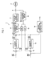
- Fig. 1 is a system configuration diagram of a control device for a permanent magnet synchronous electric motor in a first embodiment of the present invention.
- the control device 1 for a permanent magnet synchronous electric motor includes a current controller 4, coordinate transformations 6 and 11, an electric power converter 7, a band-stop filter 9, a band-pass filter 10, a resonant controller 13, and a magnet temperature estimating unit 14 to control an electric motor 2.
- a current controller 4 coordinate transformations 6 and 11
- an electric power converter 7 a band-stop filter 9, a band-pass filter 10
- a resonant controller 13 a magnet temperature estimating unit 14 to control an electric motor 2.
- two oblique lines indicate two-dimensional vectors and three oblique lines indicate three-dimensional vectors.
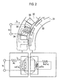
- the electric motor 2 is a three-phase permanent magnet synchronous motor (PMSM) and is configured such that a rotor 31 including permanent magnets 32 rotate inside a stator 30. Multiple slots 33 are provided in the stator 30 and a stator coil 34 are wound in each of the slots 33. A current magnetic flux is generated by supplying a three-phase electric power to the stator coil 34 and each of the permanent magnets 32 generates magnet magnetic flux. Note that a temperature sensor 35 measures the temperature of the stator coil 34.
- PMSM permanent magnet synchronous motor
- a harmonic voltage Vh is superimposed on the stator coil 34 and the temperature of the permanent magnet 32 is estimated based on a real part Rd of a harmonic impedance Zh which changes depending on a generated harmonic current value Ih.
- An equivalent circuit of the electric motor 2 can be illustrated as shown in Fig. 2 , where Rc represents the resistance value of the stator coil, Lc represents the inductance of the stator coil, Rm represents the resistance value of the permanent magnet 32, and Lm represents the inductance of the permanent magnet 32.
- M represents a mutual inductance and ⁇ represents an angular frequency of the harmonic voltage Vh.
- the resistance value Rm and the inductance Lm of the permanent magnet 32 are functions of the temperature Tm of the permanent magnet 32. Accordingly, the resistance value Rm and the value of the inductance Lm of the permanent magnet 32 changes as the temperature Tm of the permanent magnet 32 changes. In other words, the real part Rd of the harmonic impedance Zh changes. As will be described later, there is a correlative relationship between the real part Rd of the harmonic impedance Zh and the temperature Tm of the permanent magnet 32. Accordingly, the temperature Tm of the permanent magnet 32 can be estimated based on the real part Rd of the harmonic impedance Zh obtained by superimposing the harmonic voltage Vh.
- a differential unit 3 subtracts detected fundamental wave currents idsf and iqsf respectively from current command values idsf* and iqsf* on d and q axes which are based on a torque command value, the detected fundamental wave currents idsf and iqsf obtained by cutting harmonics contents from detected currents ids and iqs actually flowing in the electric motor 2.
- the current controller 4 performs a proportional-plus-integral control in such a way that a deviation between each of the current command values idsf* and iqsf* and a corresponding one of the detected fundamental wave currents idsf and iqsf are eliminated, and outputs first voltage command values vd0* and vq0*.
- a differential unit 12 subtracts detected harmonic current values idsc and iqsc respectively from harmonic current command values idsc* and iqsc* received from the outside, the detected harmonic current values idsc and iqsc obtained by cutting fundamental wave contents from the detected currents ids and iqs actually flowing in the electric motor 2.
- the harmonic current command values idsc* and iqsc* are expressed by formula (2).
- a harmonic signal superimposed on a fundamental wave for driving the electric motor 2 is given as a command value of the current.
- Ic represents the amplitude of the d-axis harmonic current command value idsc*
- ⁇ c represents the angular frequency of the d-axis harmonic current command value idsc*
- t represents time.
- the frequency of the d-axis harmonic current command value idsc* is different from the frequency of the fundamental wave.
- the harmonic current is superimposed on the d-axis component of the electric motor 2.
- the amplitude Ic of the d-axis harmonic current command value idsc* is smaller than the amplitude of the fundamental wave.
- the resonant controller 13 generates harmonic voltage command values vdsc* and vqsc* depending on the magnitude of the output of the differential unit 12.
- the resonant controller 13 can arbitrary set the amplitudes and intervals of the harmonic voltage command values vdsc* and vqsc*.
- the harmonic voltage command values vdsc* and vqsc* generated in the resonant controller 13 is expressed by formula (3).
- a pulsating vector injection method is used in the superimposing of the harmonic voltage on the fundamental wave.
- the pulsating vector injection method is a method in which the harmonic voltage is superimposed on the d-axis component of the fundamental wave in directions parallel to the d axis (both of positive and negative directions).
- Rd represents a circuit resistance value including the coil resistance value of the stator and the permanent magnet resistant value.
- the circuit resistance value also includes a resistance value of wiring between the electric motor 2 and the electric power converter 7.
- Ld represents a d-axis inductance and ⁇ r represents the angular frequency of the rotor.
- the q-axis component in the harmonic voltage command values vdsc* and vqsc* is cut and only the d-axis component is superimposed on the d-axis component of the electric motor 2. The q-axis component is cut because ⁇ r is included in the q-axis harmonic voltage command value vqsc* in formula (3).
- the value of the q-axis harmonic voltage command value vqsc* changes depending on the angular frequency of the rotor.
- the q-axis component is cut to prevent such effects by the angular frequency of the rotor.
- effects due to the q-axis inductance can be also prevented by cutting the q-axis component.
- An adder 5 superimposes the harmonic voltage command values vdsc* and vqsc* on the first voltage command values vd0* and vq0* and outputs second voltage command values vds* and vqs*.
- the coordinate tranformation 6 performs coordinate conversion on the second voltage command values vds* and vqs* which are outputs of the adder 5, and outputs three-phase voltage command values vu*, vv*, and vw*.
- the electric power converter 7 is, for example, an electric power converting circuit formed of a converter and an inverter and applies a three-phase voltage to the electric motor 2 on the basis of the three-phase voltage command values vu*, vv*, and vw*. Note that a voltage inverter or a current inverter can be used as the inverter.
- the electric motor 2 is driven by a three-phase current from the electric power converter 7 or performs regeneration.
- the current detector 8 detects three-phase currents iu, iv, and iw flowing in the electric motor 2, by using a hole element or the like.
- the coordinate transformation 11 performs coordinate conversion on the three-phase currents detected by the current detector 8 and outputs the detected currents ids and iqs on the d and q axes.
- the detected currents ids and iqs each include the fundamental wave component and the harmonic component.
- the fundamental wave component and the harmonic component included in each of the detected currents ids and iqs are separated by using the band-stop filter 9 and the band-pass filter 10.
- the band-stop filter 9 cuts the harmonic component from each of the detected currents ids and iqs and outputs the detected fundamental wave currents idsf and iqsf.
- the band-pass filter 10 cuts the fundamental wave component from each of the detected currents ids and iqs and outputs the detected harmonic current values idsc and iqsc.
- the magnet temperature estimating unit 14 includes a filter 15, band-stop filters 16 and 17, a calculator 18, and a magnet temperature estimator 19.
- the filter 15 cuts the q-axis component in the harmonic voltage command values vdsc* and vqsc* and outputs a d-axis harmonic voltage value vdsc which is the d-axis component.
- the d-axis harmonic voltage value vdsc is a voltage obtained by superimposing the harmonic voltage command values vdsc* and vqsc* on the d-axis component of the electric motor 2.
- the band-stop filter 16 cuts a frequency component on a positive side or a negative side in the d-axis harmonic voltage value vdsc depending on the direction of rotation of the electric motor 2 and thereby extracts a frequency component on the positive side or the negative side.
- the band-stop filter 17 cuts a frequency component on the positive side or the negative side and thereby extracts a frequency component on the positive side or the negative side.
- the calculator 18 calculates a harmonic impedance Zds from the voltage value and the current value outputted from the band-stop filters 16 and 17.
- the calculated harmonic impedance Zds is expressed by formula (5).
- ⁇ zd represents a phase angle of the harmonic impedance Zds.
- the calculator 18 outputs the real part Rd of the harmonic impedance Zds obtained from formula (5).
- the magnet temperature estimator 19 estimates the temperature Tm of the permanent magnet by using the real part Rd of the harmonic impedance Zds outputted from the calculator 18. As shown in Fig. 4 , there is a correlative relationship between the real part Rd of the harmonic impedance Zds and the temperature Tm of the permanent magnet. This relationship can be obtained through experiments and simulations in advance.
- the magnet temperature estimator 19 stores a map or a proportional coefficient which shows the relationship between the real part Rd of the harmonic impedance Zds and the temperature Tm of the permanent magnet and refers to the map and the real part Rd of the harmonic impedance Zds outputted from the calculator 18 to output the temperature Tm of the permanent magnet.
- the d-axis harmonic current command value idsc* is superimposed only on the d-axis component of the fundamental wave in the pulsating vector injection method to obtain the d-axis harmonic voltage value vdsc not affected by the number of revolutions of the electric motor 2 and the q-axis inductance.
- the harmonic impedance Zds is calculated by using the d-axis harmonic current command value and the d-axis harmonic voltage and the temperature Tm of the permanent magnet is estimated based on the real part Rd of the thus-calculated harmonic impedance Zds.
- the temperature Tm of the permanent magnet can be thereby accurately estimated in a wide operation range from zero speed to a high number of revolutions of the electric motor 2.
- the d-axis harmonic current command value idsc* is superimposed at predetermined intervals.
- the temperature Tm of the permanent magnet may increase depending on the frequency and amplitude of the d-axis harmonic current command value idsc*.
- the d-axis harmonic current command value idsc* is thus superimposed at predetermined intervals. This can suppress a loss of the electric motor 2 due to the d-axis harmonic current command value idsc* with a high estimation accuracy maintained for the temperature Tm of the permanent magnet.
- the amplitude of the d-axis harmonic current command value idsc* is smaller than the amplitude of the fundamental wave. If the amplitude of the d-axis harmonic current command value idsc* is larger than the amplitude of the fundamental wave, not only the operations of the electric motor 2 is affected, but also the temperature Tm of the permanent magnet may increase. Thus, in the embodiment, the amplitude of the d-axis harmonic current command value idsc* is set to be smaller than the amplitude of the fundamental wave. This can suppress the loss of the electric motor 2 due to the d-axis harmonic current command value idsc* with a high estimation accuracy maintained for the temperature Tm of the permanent magnet.
- the harmonic impedance Zds can be obtained from the d-axis harmonic current command value idsc*and the d-axis harmonic voltage value vdsc obtained by superimposing the d-axis harmonic current command value idsc*. Accordingly, the temperature Tm of the permanent magnet can be easily estimated.
- the detected harmonic current values idsc and iqsc are separated from the fundamental wave by using the band-stop filter 9 and the band-pass filter 10.
- the harmonic components can be thereby extracted at a high accuracy.
- the temperature Tm of the permanent magnet can be accurately estimated.
- a frequency component on a different side from the rotating direction of the synchronous electric motor is extracted from the d-axis harmonic current command value idsc* and the d-axis harmonic voltage value vdsc by using the band-stop filters 16 and 17. Due to this, the positive and negative of the frequencies of the fundamental wave and the d-axis harmonic current command value idsc* are different from each other even in case where the frequencies are the same. Thus, the temperature Tm of the permanent magnet can be accurately estimated without increasing the frequency of the harmonic even in an electric motor with a wide range of the number of revolutions.
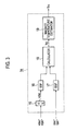
- Fig. 5 is a configuration diagram of the modified example 1 of the magnet temperature estimating unit 14.
- the magnet temperature estimating unit 14 estimates the temperature Tm of the permanent magnet in consideration of a coil temperature Tc of the stator.
- the coil temperature Tc of the stator can be obtained from the temperature sensor 35 attached to the stator coil 34 as shown in Fig. 2 .
- the coil temperature Tc and the coil resistance value Rc of the stator as shown in Fig. 6 . This relationship can be obtained through experiments and simulations in advance.
- the magnet temperature estimator 19 stores a map showing the relationship between the coil temperature Tc and the coil resistance value Rc of the stator and can estimate the coil resistance value Rc of the stator by referring to the map and the inputted coil temperature Tc of the stator. Since the coil resistance value Rc of the stator is included in the real part Rd of the harmonic impedance Zds, correcting the coil resistance value Rc of the stator by using the coil temperature Tc of the stator enables the real part Rd of the harmonic impedance Zds including the corrected coil resistance value Rc to be accurately obtained. Thus, the temperature Tm of the permanent magnet can be accurately estimated.
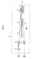
- Fig. 7 is a configuration diagram of the modified example 2 of the magnet temperature estimating unit 14.
- the modified example 2 is different from the modified example 1 in that the resistance value Rc of the stator is estimated not by using the map but through calculation by a calculator 20.
- Rc represents the resistance value at the coil temperature of T0 while Rc' represents the resistance value at the coil temperature of T1.
- ⁇ represents a resistance temperature coefficient.
- Fig. 8 is a configuration diagram of the modified example 3 of the magnet temperature estimating unit 14.
- the modified example 3 is different from the modified examples 1 and 2 in that, as shown in Fig. 8 , the magnet temperature estimating unit 14 includes a compensation calculator 30.
- the compensation calculator 30 compensates the real part Rd of the harmonic impedance Zds by using fundamental wave current values id and iq. A highly-accurate real part Rd (comp) of the harmonic impedance Zds can be thereby obtained.
- the current command values idsf * and iqsf* are used as the fundamental wave current values id and iq.
- the fundamental wave current values id and iq are not limited to these values.
- Fig. 9 is a relationship between the d-axis fundamental wave current value id and a compensation amount Cd for compensating the real part Rd of the harmonic impedance Zds.
- Fig. 10 is a relationship between a q-axis fundamental wave current value iq and a compensation amount Cq for compensating the real part Rd of the harmonic impedance Zds. As shown in Figs.
- Rd(comp) represents the real part Rd of the harmonic impedance Zds after compensation.
- the modified example 3 it is possible to compensate the real part Rd of the harmonic impedance Zds by using the fundamental wave current values id and iq and obtain a highly-accurate real part Rd(comp). Then, the temperature Tm of the permanent magnet can be accurately estimated by using the highly-accurate real part Rd(comp) of the harmonic impedance Zds. Note that the coil temperature Tc of the stator shown in the modified example 1 or 2 can be also taken in consideration in the modified example 3.
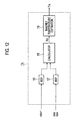
- the second embodiment is different from the first embodiment in that a d-axis component of a fundamental wave is superimposed on a harmonic voltage instead of a harmonic current. Description of points which are the same as the first embodiment is omitted and points different from the first embodiment are mainly described below.
- Fig. 11 is a system configuration diagram of a control device 1 for a permanent magnet synchronous electric motor in the second embodiment.
- a filter 21 cuts the d-axis component in detected harmonic current values idsc and iqsc outputted from the band-pass filter 10 and outputs the q-axis detected harmonic current value iqsc which is a q-axis component.
- a differential unit 12 subtracts the q-axis detected harmonic current value iqsc from a q-axis harmonic current command value iqsc* received from the outside.
- the q-axis harmonic current command value iqsc* is set to 0 so that no harmonic current is superimposed on the q-axis component of the fundamental wave. Accordingly, a q-axis harmonic voltage command value vqsc* generated in a resonant controller 13 is also 0.
- An adder 22 adds a d-axis harmonic voltage command value vdsc* received from the outside and q-axis harmonic voltage command value vqsc* outputted from the resonant controller 13.
- Vc represents amplitude
- An adder 5 superimposes the harmonic voltage command values vdsc* and vqsc* on first voltage command values vd0* and vq0* and outputs second voltage command values vds* and vqs*. Since the q-axis harmonic voltage command value vqsc* is 0, the adder 5 superimposes the d-axis harmonic voltage command value vdsc* only on the d-axis component of the fundamental wave. This can prevent effects due to a q-axis inductance. Moreover, the method of superimposing the d-axis harmonic voltage command value vdsc* is a pulsating vector injection method as in the first embodiment.
- a harmonic current in which effects of the number of revolutions of an electric motor 2 are suppressed can be thereby obtained.
- Harmonic current values idsc and iqsc obtained by superimposing the d-axis harmonic voltage command value vdsc* only on the d-axis component of the fundamental wave are outputted via the band-pass filter 10 and is expressed by formula (8).
- i dsc i qsc v dsc * / R d + j ⁇ ⁇ c ⁇ L d 0
- a calculator 18 calculates a harmonic impedance Zds on the basis of formulae (7) and (8) shown above.
- the harmonic impedance Zds is expressed by formula (9).
- the calculator 18 outputs the real part Rd of the harmonic impedance Zds obtained from formula (9).
- the magnet temperature estimator 19 estimates the temperature Tm of the permanent magnet by using the real part Rd of the harmonic impedance Zds outputted from the calculator 18.
- the d-axis harmonic voltage command value vdsc* is superimposed only on the d-axis components of the fundamental wave in the pulsating vector injection method and the d-axis harmonic current value idsc in which the effects of the number of revolutions of the electric motor 2 are suppressed can be obtained.
- the harmonic impedance Zds is calculated by using the d-axis harmonic voltage command value vdsc* and the d-axis harmonic current value idsc and the temperature Tm of the permanent magnet is estimated based on the real part Rd of the thus-calculated harmonic impedance Zds.
- the temperature Tm of the permanent magnet can be thereby accurately estimated in a wide operation range from zero speed to a high number of revolutions of the electric motor 2.
- a coil resistance value Rc can be corrected by using a coil temperature Tc of the stator as in the first embodiment.
- the real part Rd of the harmonic impedance Zds can be compensated by using fundamental wave current values id and iq as in the first embodiment.
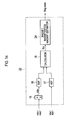
- Fig. 13 is a system configuration diagram of a control device 1 for a permanent magnet synchronous electric motor in the third embodiment.
- the third embodiment is different from the first embodiment in that the magnetization amount of a permanent magnet is estimated instead of the temperature Tm of the permanent magnet. Description of points which are the same as the first embodiment is omitted and points different from the first embodiment are mainly described below.
- the control device 1 of the embodiment includes a magnet magnetization amount estimating unit 23.
- the magnet magnetization amount estimating unit 23 estimates the magnetization amount of the permanent magnet from a real part Rd of a harmonic impedance Zds calculated by a calculator 18.
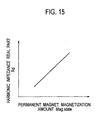
- a calculator 18 As shown in Fig. 15 , there is a correlative relationship between the magnetization amount of the permanent magnet and the real part Rd of the harmonic impedance Zds. This relationship can be obtained through experiments and simulations in advance.
- the magnet magnetization amount estimating unit 23 stores a map showing the relationship between the magnetization amount of the permanent magnet and the real part Rd of the harmonic impedance Zds and refers to the map and the real part of the harmonic impedance Zds outputted from the calculator 18 to output the magnetization amount of the permanent magnet.
- the calculation of the real part Rd of the harmonic impedance Zds can be performed without being affected by the number of revolutions of an electric motor 2 and a q-axis inductance as in the first embodiment.
- the magnetization amount of the permanent magnet can be estimated based on the real part Rd of the harmonic impedance Zds.
- the magnetization amount of the permanent magnet can be thereby accurately estimated in a wide operation range from zero speed to a high number of revolutions of the electric motor 2.
- a coil resistance value can be corrected by using a coil temperature of the stator as in the first embodiment.
- the real part Rd of the harmonic impedance Zds can be compensated by using fundamental wave current values id and iq as in the first embodiment.
Landscapes
- Engineering & Computer Science (AREA)
- Power Engineering (AREA)
- Control Of Ac Motors In General (AREA)
- Control Of Electric Motors In General (AREA)
Priority Applications (4)
| Application Number | Priority Date | Filing Date | Title |
|---|---|---|---|
| EP14380002.7A EP2894784B1 (de) | 2014-01-13 | 2014-01-13 | Magnettemperaturschätzungssystem für elektrischen Synchronmotoren |
| CN201410377911.6A CN104779876B (zh) | 2014-01-13 | 2014-08-04 | 用于同步电机的磁体温度估计系统 |
| US14/450,866 US9438145B2 (en) | 2014-01-13 | 2014-08-04 | Magnet temperature estimating system for synchronous electric motor |
| JP2014160628A JP6459286B2 (ja) | 2014-01-13 | 2014-08-06 | 同期電動機の磁石温度推定システム |
Applications Claiming Priority (1)
| Application Number | Priority Date | Filing Date | Title |
|---|---|---|---|
| EP14380002.7A EP2894784B1 (de) | 2014-01-13 | 2014-01-13 | Magnettemperaturschätzungssystem für elektrischen Synchronmotoren |
Publications (2)
| Publication Number | Publication Date |
|---|---|
| EP2894784A1 true EP2894784A1 (de) | 2015-07-15 |
| EP2894784B1 EP2894784B1 (de) | 2021-05-26 |
Family
ID=50073124
Family Applications (1)
| Application Number | Title | Priority Date | Filing Date |
|---|---|---|---|
| EP14380002.7A Active EP2894784B1 (de) | 2014-01-13 | 2014-01-13 | Magnettemperaturschätzungssystem für elektrischen Synchronmotoren |
Country Status (4)
| Country | Link |
|---|---|
| US (1) | US9438145B2 (de) |
| EP (1) | EP2894784B1 (de) |
| JP (1) | JP6459286B2 (de) |
| CN (1) | CN104779876B (de) |
Cited By (3)
| Publication number | Priority date | Publication date | Assignee | Title |
|---|---|---|---|---|
| US20210234496A1 (en) * | 2020-01-28 | 2021-07-29 | Mazda Motor Corporation | Magnet temperature estimating device for motor and hybrid vehicle provided with the same |
| WO2022243175A1 (de) * | 2021-05-19 | 2022-11-24 | Volkswagen Aktiengesellschaft | Verfahren und vorrichtung zum schätzen einer rotortemperatur eines rotors einer elektrischen maschine |
| LU507046B1 (de) * | 2024-04-25 | 2025-10-27 | Wilo Se | Verfahren zur Bestimmung der Temperatur der Statorwicklung eines Elektromotors und zugehöriger Elektromotor |
Families Citing this family (15)
| Publication number | Priority date | Publication date | Assignee | Title |
|---|---|---|---|---|
| US9893598B2 (en) * | 2013-04-26 | 2018-02-13 | Mitsubishi Electric Corporation | Magnet temperature estimation device for permanent magnet motor and magnet temperature estimation method for permanent magnet motor |
| US9372235B2 (en) * | 2014-09-30 | 2016-06-21 | Deere & Company | Methods of estimating rotor magnet temperature and systems thereof |
| JP6766398B2 (ja) * | 2016-03-28 | 2020-10-14 | 日産自動車株式会社 | 磁石温度推定方法、及び、磁石温度推定装置 |
| CN105811832B (zh) * | 2016-05-06 | 2018-04-03 | 湖南大学 | 永磁同步电机定子温度的估计方法、装置及系统 |
| JP6769268B2 (ja) * | 2016-12-01 | 2020-10-14 | 日産自動車株式会社 | 磁石温度推定システム、及び、モータ |
| JP6711326B2 (ja) * | 2017-07-14 | 2020-06-17 | 株式会社デンソー | 回転電機の駆動システム |
| JP6929191B2 (ja) * | 2017-10-19 | 2021-09-01 | 日産自動車株式会社 | 巻線温度推定システム、及び巻線温度推定方法 |
| DE112017008161T5 (de) * | 2017-11-24 | 2020-09-03 | Mitsubishi Electric Corporation | Rotierende elektrische Maschinenvorrichtung und rotierendes elektrisches Maschinenvorrichtungs-Steuerverfahren |
| US11387757B2 (en) | 2019-09-04 | 2022-07-12 | GM Global Technology Operations LLC | Inductance-based estimation of rotor magnet temperature |
| CN112230062B (zh) * | 2020-09-21 | 2022-01-07 | 瑞声新能源发展(常州)有限公司科教城分公司 | 获取电机静态阻抗的方法、电机监控系统、设备和介质 |
| EP4009501A1 (de) | 2020-12-02 | 2022-06-08 | pro-micron GmbH | Zustandsüberwachung für ein rotierendes element, insbesondere für den rotor eines elektromotors |
| JP7578051B2 (ja) * | 2021-04-06 | 2024-11-06 | トヨタ自動車株式会社 | モータ温度推定システム、方法及びプログラム |
| JP7804484B2 (ja) * | 2022-02-24 | 2026-01-22 | 日産自動車株式会社 | ロータ磁石温度推定方法及びロータ磁石温度推定装置 |
| FR3145612A1 (fr) | 2023-02-06 | 2024-08-09 | IFP Energies Nouvelles | Procédé de détermination en temps réel de la température d’un rotor d’une machine électrique |
| JP2025177433A (ja) * | 2024-05-23 | 2025-12-05 | Astemo株式会社 | モータ制御装置およびモータ制御方法 |
Citations (2)
| Publication number | Priority date | Publication date | Assignee | Title |
|---|---|---|---|---|
| JP2003235286A (ja) * | 2002-02-13 | 2003-08-22 | Nissan Motor Co Ltd | 同期機の制御装置 |
| JP2007006613A (ja) | 2005-06-23 | 2007-01-11 | Hitachi Industrial Equipment Systems Co Ltd | 永久磁石式回転電機の制御装置および永久磁石式回転電機の温度推定方法 |
Family Cites Families (5)
| Publication number | Priority date | Publication date | Assignee | Title |
|---|---|---|---|---|
| JP4687846B2 (ja) * | 2001-03-26 | 2011-05-25 | 株式会社安川電機 | 同期電動機の磁極位置推定方法および制御装置 |
| JP4799045B2 (ja) * | 2005-05-17 | 2011-10-19 | 株式会社東京精密 | 工作機械 |
| JP2008206338A (ja) * | 2007-02-21 | 2008-09-04 | Toyota Motor Corp | 回転電機の駆動制御装置および車両 |
| US7839108B2 (en) * | 2008-01-24 | 2010-11-23 | Gm Global Technology Operations, Inc. | Electric motor stator winding temperature estimation |
| US9602043B2 (en) * | 2014-08-29 | 2017-03-21 | General Electric Company | Magnet management in electric machines |
-
2014
- 2014-01-13 EP EP14380002.7A patent/EP2894784B1/de active Active
- 2014-08-04 CN CN201410377911.6A patent/CN104779876B/zh active Active
- 2014-08-04 US US14/450,866 patent/US9438145B2/en active Active
- 2014-08-06 JP JP2014160628A patent/JP6459286B2/ja active Active
Patent Citations (2)
| Publication number | Priority date | Publication date | Assignee | Title |
|---|---|---|---|---|
| JP2003235286A (ja) * | 2002-02-13 | 2003-08-22 | Nissan Motor Co Ltd | 同期機の制御装置 |
| JP2007006613A (ja) | 2005-06-23 | 2007-01-11 | Hitachi Industrial Equipment Systems Co Ltd | 永久磁石式回転電機の制御装置および永久磁石式回転電機の温度推定方法 |
Cited By (5)
| Publication number | Priority date | Publication date | Assignee | Title |
|---|---|---|---|---|
| US20210234496A1 (en) * | 2020-01-28 | 2021-07-29 | Mazda Motor Corporation | Magnet temperature estimating device for motor and hybrid vehicle provided with the same |
| US11543302B2 (en) * | 2020-01-28 | 2023-01-03 | Mazda Motor Corporation | Magnet temperature estimating device for motor and hybrid vehicle provided with the same |
| WO2022243175A1 (de) * | 2021-05-19 | 2022-11-24 | Volkswagen Aktiengesellschaft | Verfahren und vorrichtung zum schätzen einer rotortemperatur eines rotors einer elektrischen maschine |
| LU507046B1 (de) * | 2024-04-25 | 2025-10-27 | Wilo Se | Verfahren zur Bestimmung der Temperatur der Statorwicklung eines Elektromotors und zugehöriger Elektromotor |
| EP4641916A1 (de) * | 2024-04-25 | 2025-10-29 | Wilo Se | Bestimmung der temperatur der statorwicklung eines elektromotors |
Also Published As
| Publication number | Publication date |
|---|---|
| CN104779876B (zh) | 2017-09-29 |
| JP6459286B2 (ja) | 2019-01-30 |
| US9438145B2 (en) | 2016-09-06 |
| EP2894784B1 (de) | 2021-05-26 |
| CN104779876A (zh) | 2015-07-15 |
| JP2015133890A (ja) | 2015-07-23 |
| US20150200614A1 (en) | 2015-07-16 |
Similar Documents
| Publication | Publication Date | Title |
|---|---|---|
| EP2894784B1 (de) | Magnettemperaturschätzungssystem für elektrischen Synchronmotoren | |
| EP2894782B1 (de) | Drehmomentschätzungssystem für elektrischen Synchronmotor | |
| CN100517947C (zh) | 估计电机中磁极位置的方法以及基于所述估计位置控制该电机的装置 | |
| CN102969967B (zh) | 用于同步电机及逆变器装置的无传感器控制装置 | |
| US9806656B1 (en) | Fault tolerant phase current measurement for motor control systems | |
| EP3451526A1 (de) | Fehlerbestimmungsvorrichtung für eine steuerungsvorrichtung einer rotierenden maschine und fehlerbestimmungsverfahren | |
| EP2930843B1 (de) | Phasenstrommessungsdiagnose | |
| US20170264227A1 (en) | Inverter control device and motor drive system | |
| CN113866480B (zh) | 用于马达控制系统的相电流测量中的偏移误差的检测 | |
| US20150137720A1 (en) | Synchronous machine control device | |
| US20160218652A1 (en) | Control device | |
| US9419555B2 (en) | Synchronous machine control apparatus | |
| JP3707528B2 (ja) | 交流電動機の制御方法およびその制御装置 | |
| CN102647144B (zh) | 用于估计同步磁阻电动机的转子角度的方法和设备 | |
| US9231511B2 (en) | Control device of AC rotating machine | |
| EP3442111A1 (de) | Steuerungsvorrichtung und steuerungsverfahren | |
| JP6766398B2 (ja) | 磁石温度推定方法、及び、磁石温度推定装置 | |
| JP6716993B2 (ja) | 磁石温度推定方法、及び、磁石温度推定装置 | |
| JP6108114B2 (ja) | 永久磁石形同期電動機の制御装置 | |
| US20180205337A1 (en) | Method and a System for Operating a Variable Speed Motor | |
| JP2010057210A (ja) | 交流電動機の制御装置 |
Legal Events
| Date | Code | Title | Description |
|---|---|---|---|
| PUAI | Public reference made under article 153(3) epc to a published international application that has entered the european phase |
Free format text: ORIGINAL CODE: 0009012 |
|
| 17P | Request for examination filed |
Effective date: 20140113 |
|
| AK | Designated contracting states |
Kind code of ref document: A1 Designated state(s): AL AT BE BG CH CY CZ DE DK EE ES FI FR GB GR HR HU IE IS IT LI LT LU LV MC MK MT NL NO PL PT RO RS SE SI SK SM TR |
|
| AX | Request for extension of the european patent |
Extension state: BA ME |
|
| STAA | Information on the status of an ep patent application or granted ep patent |
Free format text: STATUS: EXAMINATION IS IN PROGRESS |
|
| 17Q | First examination report despatched |
Effective date: 20170404 |
|
| REG | Reference to a national code |
Ref country code: DE Ref legal event code: R079 Ref document number: 602014077684 Country of ref document: DE Free format text: PREVIOUS MAIN CLASS: H02P0029000000 Ipc: H02P0029660000 |
|
| GRAP | Despatch of communication of intention to grant a patent |
Free format text: ORIGINAL CODE: EPIDOSNIGR1 |
|
| STAA | Information on the status of an ep patent application or granted ep patent |
Free format text: STATUS: GRANT OF PATENT IS INTENDED |
|
| RIC1 | Information provided on ipc code assigned before grant |
Ipc: H02P 29/66 20160101AFI20210209BHEP Ipc: H02P 6/34 20160101ALI20210209BHEP Ipc: H02P 23/14 20060101ALI20210209BHEP |
|
| INTG | Intention to grant announced |
Effective date: 20210301 |
|
| RIN1 | Information on inventor provided before grant (corrected) |
Inventor name: DIAZ REIGOSA, DAVID Inventor name: KATO, TAKASHI Inventor name: BRIZ DEL BLANCO, FERNANDO Inventor name: YOSHIDA, HIDEO |
|
| GRAS | Grant fee paid |
Free format text: ORIGINAL CODE: EPIDOSNIGR3 |
|
| GRAA | (expected) grant |
Free format text: ORIGINAL CODE: 0009210 |
|
| STAA | Information on the status of an ep patent application or granted ep patent |
Free format text: STATUS: THE PATENT HAS BEEN GRANTED |
|
| AK | Designated contracting states |
Kind code of ref document: B1 Designated state(s): AL AT BE BG CH CY CZ DE DK EE ES FI FR GB GR HR HU IE IS IT LI LT LU LV MC MK MT NL NO PL PT RO RS SE SI SK SM TR |
|
| REG | Reference to a national code |
Ref country code: GB Ref legal event code: FG4D |
|
| REG | Reference to a national code |
Ref country code: CH Ref legal event code: EP |
|
| REG | Reference to a national code |
Ref country code: DE Ref legal event code: R096 Ref document number: 602014077684 Country of ref document: DE |
|
| REG | Reference to a national code |
Ref country code: AT Ref legal event code: REF Ref document number: 1397252 Country of ref document: AT Kind code of ref document: T Effective date: 20210615 |
|
| REG | Reference to a national code |
Ref country code: IE Ref legal event code: FG4D |
|
| REG | Reference to a national code |
Ref country code: LT Ref legal event code: MG9D |
|
| REG | Reference to a national code |
Ref country code: AT Ref legal event code: MK05 Ref document number: 1397252 Country of ref document: AT Kind code of ref document: T Effective date: 20210526 |
|
| PG25 | Lapsed in a contracting state [announced via postgrant information from national office to epo] |
Ref country code: HR Free format text: LAPSE BECAUSE OF FAILURE TO SUBMIT A TRANSLATION OF THE DESCRIPTION OR TO PAY THE FEE WITHIN THE PRESCRIBED TIME-LIMIT Effective date: 20210526 Ref country code: BG Free format text: LAPSE BECAUSE OF FAILURE TO SUBMIT A TRANSLATION OF THE DESCRIPTION OR TO PAY THE FEE WITHIN THE PRESCRIBED TIME-LIMIT Effective date: 20210826 Ref country code: AT Free format text: LAPSE BECAUSE OF FAILURE TO SUBMIT A TRANSLATION OF THE DESCRIPTION OR TO PAY THE FEE WITHIN THE PRESCRIBED TIME-LIMIT Effective date: 20210526 Ref country code: LT Free format text: LAPSE BECAUSE OF FAILURE TO SUBMIT A TRANSLATION OF THE DESCRIPTION OR TO PAY THE FEE WITHIN THE PRESCRIBED TIME-LIMIT Effective date: 20210526 Ref country code: FI Free format text: LAPSE BECAUSE OF FAILURE TO SUBMIT A TRANSLATION OF THE DESCRIPTION OR TO PAY THE FEE WITHIN THE PRESCRIBED TIME-LIMIT Effective date: 20210526 |
|
| REG | Reference to a national code |
Ref country code: NL Ref legal event code: MP Effective date: 20210526 |
|
| PG25 | Lapsed in a contracting state [announced via postgrant information from national office to epo] |
Ref country code: GR Free format text: LAPSE BECAUSE OF FAILURE TO SUBMIT A TRANSLATION OF THE DESCRIPTION OR TO PAY THE FEE WITHIN THE PRESCRIBED TIME-LIMIT Effective date: 20210827 Ref country code: IS Free format text: LAPSE BECAUSE OF FAILURE TO SUBMIT A TRANSLATION OF THE DESCRIPTION OR TO PAY THE FEE WITHIN THE PRESCRIBED TIME-LIMIT Effective date: 20210926 Ref country code: LV Free format text: LAPSE BECAUSE OF FAILURE TO SUBMIT A TRANSLATION OF THE DESCRIPTION OR TO PAY THE FEE WITHIN THE PRESCRIBED TIME-LIMIT Effective date: 20210526 Ref country code: RS Free format text: LAPSE BECAUSE OF FAILURE TO SUBMIT A TRANSLATION OF THE DESCRIPTION OR TO PAY THE FEE WITHIN THE PRESCRIBED TIME-LIMIT Effective date: 20210526 Ref country code: SE Free format text: LAPSE BECAUSE OF FAILURE TO SUBMIT A TRANSLATION OF THE DESCRIPTION OR TO PAY THE FEE WITHIN THE PRESCRIBED TIME-LIMIT Effective date: 20210526 Ref country code: PT Free format text: LAPSE BECAUSE OF FAILURE TO SUBMIT A TRANSLATION OF THE DESCRIPTION OR TO PAY THE FEE WITHIN THE PRESCRIBED TIME-LIMIT Effective date: 20210927 Ref country code: NO Free format text: LAPSE BECAUSE OF FAILURE TO SUBMIT A TRANSLATION OF THE DESCRIPTION OR TO PAY THE FEE WITHIN THE PRESCRIBED TIME-LIMIT Effective date: 20210826 Ref country code: PL Free format text: LAPSE BECAUSE OF FAILURE TO SUBMIT A TRANSLATION OF THE DESCRIPTION OR TO PAY THE FEE WITHIN THE PRESCRIBED TIME-LIMIT Effective date: 20210526 |
|
| PG25 | Lapsed in a contracting state [announced via postgrant information from national office to epo] |
Ref country code: NL Free format text: LAPSE BECAUSE OF FAILURE TO SUBMIT A TRANSLATION OF THE DESCRIPTION OR TO PAY THE FEE WITHIN THE PRESCRIBED TIME-LIMIT Effective date: 20210526 |
|
| PG25 | Lapsed in a contracting state [announced via postgrant information from national office to epo] |
Ref country code: SK Free format text: LAPSE BECAUSE OF FAILURE TO SUBMIT A TRANSLATION OF THE DESCRIPTION OR TO PAY THE FEE WITHIN THE PRESCRIBED TIME-LIMIT Effective date: 20210526 Ref country code: SM Free format text: LAPSE BECAUSE OF FAILURE TO SUBMIT A TRANSLATION OF THE DESCRIPTION OR TO PAY THE FEE WITHIN THE PRESCRIBED TIME-LIMIT Effective date: 20210526 Ref country code: CZ Free format text: LAPSE BECAUSE OF FAILURE TO SUBMIT A TRANSLATION OF THE DESCRIPTION OR TO PAY THE FEE WITHIN THE PRESCRIBED TIME-LIMIT Effective date: 20210526 Ref country code: DK Free format text: LAPSE BECAUSE OF FAILURE TO SUBMIT A TRANSLATION OF THE DESCRIPTION OR TO PAY THE FEE WITHIN THE PRESCRIBED TIME-LIMIT Effective date: 20210526 Ref country code: EE Free format text: LAPSE BECAUSE OF FAILURE TO SUBMIT A TRANSLATION OF THE DESCRIPTION OR TO PAY THE FEE WITHIN THE PRESCRIBED TIME-LIMIT Effective date: 20210526 Ref country code: ES Free format text: LAPSE BECAUSE OF FAILURE TO SUBMIT A TRANSLATION OF THE DESCRIPTION OR TO PAY THE FEE WITHIN THE PRESCRIBED TIME-LIMIT Effective date: 20210526 Ref country code: RO Free format text: LAPSE BECAUSE OF FAILURE TO SUBMIT A TRANSLATION OF THE DESCRIPTION OR TO PAY THE FEE WITHIN THE PRESCRIBED TIME-LIMIT Effective date: 20210526 |
|
| REG | Reference to a national code |
Ref country code: DE Ref legal event code: R097 Ref document number: 602014077684 Country of ref document: DE |
|
| PLBE | No opposition filed within time limit |
Free format text: ORIGINAL CODE: 0009261 |
|
| STAA | Information on the status of an ep patent application or granted ep patent |
Free format text: STATUS: NO OPPOSITION FILED WITHIN TIME LIMIT |
|
| 26N | No opposition filed |
Effective date: 20220301 |
|
| PG25 | Lapsed in a contracting state [announced via postgrant information from national office to epo] |
Ref country code: IS Free format text: LAPSE BECAUSE OF FAILURE TO SUBMIT A TRANSLATION OF THE DESCRIPTION OR TO PAY THE FEE WITHIN THE PRESCRIBED TIME-LIMIT Effective date: 20210926 Ref country code: AL Free format text: LAPSE BECAUSE OF FAILURE TO SUBMIT A TRANSLATION OF THE DESCRIPTION OR TO PAY THE FEE WITHIN THE PRESCRIBED TIME-LIMIT Effective date: 20210526 |
|
| PG25 | Lapsed in a contracting state [announced via postgrant information from national office to epo] |
Ref country code: IT Free format text: LAPSE BECAUSE OF FAILURE TO SUBMIT A TRANSLATION OF THE DESCRIPTION OR TO PAY THE FEE WITHIN THE PRESCRIBED TIME-LIMIT Effective date: 20210526 |
|
| PG25 | Lapsed in a contracting state [announced via postgrant information from national office to epo] |
Ref country code: MC Free format text: LAPSE BECAUSE OF FAILURE TO SUBMIT A TRANSLATION OF THE DESCRIPTION OR TO PAY THE FEE WITHIN THE PRESCRIBED TIME-LIMIT Effective date: 20210526 |
|
| REG | Reference to a national code |
Ref country code: CH Ref legal event code: PL |
|
| REG | Reference to a national code |
Ref country code: BE Ref legal event code: MM Effective date: 20220131 |
|
| PG25 | Lapsed in a contracting state [announced via postgrant information from national office to epo] |
Ref country code: LU Free format text: LAPSE BECAUSE OF NON-PAYMENT OF DUE FEES Effective date: 20220113 |
|
| PG25 | Lapsed in a contracting state [announced via postgrant information from national office to epo] |
Ref country code: BE Free format text: LAPSE BECAUSE OF NON-PAYMENT OF DUE FEES Effective date: 20220131 |
|
| PG25 | Lapsed in a contracting state [announced via postgrant information from national office to epo] |
Ref country code: LI Free format text: LAPSE BECAUSE OF NON-PAYMENT OF DUE FEES Effective date: 20220131 Ref country code: CH Free format text: LAPSE BECAUSE OF NON-PAYMENT OF DUE FEES Effective date: 20220131 |
|
| PG25 | Lapsed in a contracting state [announced via postgrant information from national office to epo] |
Ref country code: IE Free format text: LAPSE BECAUSE OF NON-PAYMENT OF DUE FEES Effective date: 20220113 |
|
| PG25 | Lapsed in a contracting state [announced via postgrant information from national office to epo] |
Ref country code: HU Free format text: LAPSE BECAUSE OF FAILURE TO SUBMIT A TRANSLATION OF THE DESCRIPTION OR TO PAY THE FEE WITHIN THE PRESCRIBED TIME-LIMIT; INVALID AB INITIO Effective date: 20140113 |
|
| PG25 | Lapsed in a contracting state [announced via postgrant information from national office to epo] |
Ref country code: MK Free format text: LAPSE BECAUSE OF FAILURE TO SUBMIT A TRANSLATION OF THE DESCRIPTION OR TO PAY THE FEE WITHIN THE PRESCRIBED TIME-LIMIT Effective date: 20210526 Ref country code: CY Free format text: LAPSE BECAUSE OF FAILURE TO SUBMIT A TRANSLATION OF THE DESCRIPTION OR TO PAY THE FEE WITHIN THE PRESCRIBED TIME-LIMIT Effective date: 20210526 |
|
| PG25 | Lapsed in a contracting state [announced via postgrant information from national office to epo] |
Ref country code: TR Free format text: LAPSE BECAUSE OF FAILURE TO SUBMIT A TRANSLATION OF THE DESCRIPTION OR TO PAY THE FEE WITHIN THE PRESCRIBED TIME-LIMIT Effective date: 20210526 |
|
| PG25 | Lapsed in a contracting state [announced via postgrant information from national office to epo] |
Ref country code: MT Free format text: LAPSE BECAUSE OF FAILURE TO SUBMIT A TRANSLATION OF THE DESCRIPTION OR TO PAY THE FEE WITHIN THE PRESCRIBED TIME-LIMIT Effective date: 20210526 |
|
| PGFP | Annual fee paid to national office [announced via postgrant information from national office to epo] |
Ref country code: GB Payment date: 20251220 Year of fee payment: 13 |
|
| PGFP | Annual fee paid to national office [announced via postgrant information from national office to epo] |
Ref country code: FR Payment date: 20251217 Year of fee payment: 13 |
|
| PGFP | Annual fee paid to national office [announced via postgrant information from national office to epo] |
Ref country code: DE Payment date: 20251217 Year of fee payment: 13 |