EP2894259B1 - Écluse - Google Patents
Écluse Download PDFInfo
- Publication number
- EP2894259B1 EP2894259B1 EP12884150.9A EP12884150A EP2894259B1 EP 2894259 B1 EP2894259 B1 EP 2894259B1 EP 12884150 A EP12884150 A EP 12884150A EP 2894259 B1 EP2894259 B1 EP 2894259B1
- Authority
- EP
- European Patent Office
- Prior art keywords
- section
- torsion
- rail
- cross
- gate
- Prior art date
- Legal status (The legal status is an assumption and is not a legal conclusion. Google has not performed a legal analysis and makes no representation as to the accuracy of the status listed.)
- Not-in-force
Links
Images


Classifications
-
- E—FIXED CONSTRUCTIONS
- E02—HYDRAULIC ENGINEERING; FOUNDATIONS; SOIL SHIFTING
- E02B—HYDRAULIC ENGINEERING
- E02B13/00—Irrigation ditches, i.e. gravity flow, open channel water distribution systems
- E02B13/02—Closures for irrigation conduits
-
- E—FIXED CONSTRUCTIONS
- E02—HYDRAULIC ENGINEERING; FOUNDATIONS; SOIL SHIFTING
- E02B—HYDRAULIC ENGINEERING
- E02B7/00—Barrages or weirs; Layout, construction, methods of, or devices for, making same
- E02B7/20—Movable barrages; Lock or dry-dock gates
- E02B7/38—Rolling gates or gates moving horizontally in their own plane, e.g. by sliding
-
- E—FIXED CONSTRUCTIONS
- E02—HYDRAULIC ENGINEERING; FOUNDATIONS; SOIL SHIFTING
- E02B—HYDRAULIC ENGINEERING
- E02B7/00—Barrages or weirs; Layout, construction, methods of, or devices for, making same
- E02B7/20—Movable barrages; Lock or dry-dock gates
- E02B7/40—Swinging or turning gates
- E02B7/44—Hinged-leaf gates
-
- E—FIXED CONSTRUCTIONS
- E02—HYDRAULIC ENGINEERING; FOUNDATIONS; SOIL SHIFTING
- E02B—HYDRAULIC ENGINEERING
- E02B7/00—Barrages or weirs; Layout, construction, methods of, or devices for, making same
- E02B7/20—Movable barrages; Lock or dry-dock gates
- E02B7/54—Sealings for gates
-
- E—FIXED CONSTRUCTIONS
- E02—HYDRAULIC ENGINEERING; FOUNDATIONS; SOIL SHIFTING
- E02B—HYDRAULIC ENGINEERING
- E02B8/00—Details of barrages or weirs ; Energy dissipating devices carried by lock or dry-dock gates
- E02B8/04—Valves, slides, or the like; Arrangements therefor; Submerged sluice gates
Definitions
- the present invention relates to a sluice gate installed in a sluice for water flow or ships.
- the gate accommodates high tide water, tsunami, high water (reverse flow from a main river to a tributary stream), ocean waves, floodwood flow etc. and includes a land lock gate.
- a large scale gate provided against high tide water, tsunami etc. is well known.
- the gate of Patent Document 1 is a flap gate, which includes a gate leaf (torsion structure) that has a thin wall closed cross-section, and axle type supports supporting the gate leaf.
- the gate leaf is supported by a foundation ground via the axle type supports and rotates around the axles.
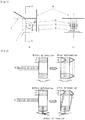
- Fig. 1 shows an example of an axle type support for a flap gate, where Fig. 1 a shows its side elevation view and Fig. 1b shows a cross-section cut along line A-A of Fig. 1 a.
- Reference numeral 6 denotes a gate leaf (solid line, in a closed position), 7 denotes the gate leaf (dotted line, in an open position), 8 denotes a bottom support, 9 denotes a rotation axle, and 10 denotes a bracket.
- the gate leaves 6 and 7 are fixed by welding etc. to the bracket 10 that is connected to the rotation axle 9.
- the bottom support 8 is sustained by a foundation ground.
- the gate leaf (in its open position) 7 When the gate is not in use, the gate leaf (in its open position) 7 is stored horizontally underwater as the dotted line shows. When in use, the gate leaf (in its open position) 7 rotates around the rotation axle 9, rises up, and moves to the position of the gate leaf (in its closed position) 6 of the solid line.
- Fig. 2 explains difference in characteristics of deformation between torsion and bending type structures.
- Fig. 2a shows the bending type structure and
- Fig. 2b shows the torsion structure, where L denotes span length.
- a characteristic in the deformation of the bending type structure is the parallel displacement of its cross-section while that of the torsion structure is the in-plane rotation of its cross-section.
- the rotation center of the cross-section is the axle type support that restricts the displacement of the cross-section.
- the torsion structure is distinguished from the bending type structure by whether or not there is a restriction point on the cross-section.
- the torsion structure is characterized by (1) the thin wall closed cross-section and (2) the cross-sectional restriction.
- the torsion structure resists a load by square of its closed cross-sectional area while the bending type structure and the axial type structure resist by the cross-sectional secondary moment and axial rigidity of their members, respectively.
- a load applied to the torsion structure is transmitted to a sectional restriction point, and a torsion moment composed by the load and the reaction force at the restriction point is transmitted to the support span terminal of the structure due to a sectional torsion rigidity while the loads applied to the bending and axial type structures are directly transmitted to their support span terminals due to a sectional shearing rigidity and an axial rigidity, respectively.
- the bending type and axial type structures are 3-dimensional structures whereas the torsion structure may be classified as 2.5-dimensional structure.
- Patent document 2 discloses a sluice gate according to the preamble of claims 1 and 2, and discloses in particular a waterproof device of a sliding door type for opening and closing the entrance of a structure.
- the door of said waterproof device is formed in a box shape and is able to slide along rails.
- the torsion structure has an overwhelming advantage in cost, its application to a gate has been limited to a flap gate that is fixed on the foundation ground via axle type supports.
- This invention enables application of the torsion structure to, for instance, a tidal gate that moves laterally.
- the application is also applicable to a super large tidal gate having a structure support span between 200 to 600 m and more.
- This invention shows resolutions to the following problems, contributing to implementation of a tidal gate of the torsion structure.
- the invention implements the following gate functions: (1.1) Free twisting deformation, (1.2) Water pressure support while the gate is completely closed and (1.3) Water pressure support during gate movement. Following are explanations of each function.
- a twisting deformation occurs in the torsion structure due to an applied load like water pressure, its own weight etc. As an additional bending deformation will occur in the structure if the center line of twisting in the structure is not straight, linearity of the line should be maintained so that a free twisting deformation without any additional restriction is possible.
- the gate moves laterally while it is subjected to water pressure that corresponds to a gate operation condition.
- the lateral movement is made without the rollers running off the rail.
- the rail foundation While a rail is installed for lateral movement of a torsion tidal gate, the rail foundation may be deformed due to uneven settlement of the foundation ground after construction of the gate has started. Lateral movement of the gate is made possible even if any uneven settlement occurs in the rail foundation.
- Twisting of a structure includes simple torsion and bending torsion.
- Simple torsion generates the simple torsion moment, thereby generating the shearing stress of the simple torsion on a cross-section of the structure while bending torsion generates the bending -torsion moment, resulting in adding the shearing stress of the bending torsion to the shearing stress of the simple torsion.
- the shearing stress of the simple torsion distributes uniformly over the cross-section whereas the shearing stress of the bending torsion distributes nonuniformly like big waveforms over the cross-section, resulting in increase in the maximum stress of their sum.
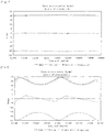
- Fig. 3 through Fig. 11 are calculation examples.
- Fig. 4 and Fig. 5 show the simple torsion and the bending torsion of the gate leaf of Fig. 3 , respectively.
- Fig. 7 and Fig. 8 show the simple torsion and the bending torsion of the gate leaf of Fig. 6 , respectively.
- Fig. 10 and Fig. 11 show the simple torsion and the bending torsion of the gate leaf of Fig. 9 , respectively.
- a sluice gate which is equipped with a gate leaf of the torsion structure, a rail, and a plurality of axle type supports that works as a restriction point and moves along the rail, is proposed to implement a laterally sliding type opening/closing gate of the torsion structure at a reasonable cost.
- the axle type support includes a roller, cross-sectional form of the head region of the rail is a convex circular arc, and cross-sectional form of the tread surface of the roller is a concave circular arc whose radius corresponds to the radius of the convex circular arc of the head region of the rail.
- the roller and the rail work as an axle type support due to their good fit.
- rollers arranged so as to sandwich the head region of the rail may be provided.
- Preferred embodiments are defined in the dependent claims.
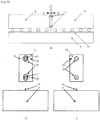
- Fig. 12 shows a laterally sliding type opening/closing tidal gate. The figure represents the left half of a sluice gate viewed from the seaside of the tidal gate.
- Fig. 12a is a plan view and Fig. 12b is an elevation view.
- sluice gate of Fig. 12 is in either state 1 or 2.
- axle type support 100 denotes an axle type support that works as a restriction point of the gate leaf 1 (may be referred to as "torsion structure 1" hereafter) and moves along the rail described later.
- a plurality of the axle type support 100 is provided at the gate leaf bottom. The plurality of the axle type support 100 is aligned according to the rail arrangement (for instance, in a linear fashion). Refer to Fig. 15 through Fig. 18 and description thereof for a detailed composition of the axle type support.
- the gate leaf 2 in the completely opened state is stored in the storage dock 3. During use, the gate is moved laterally up to the position of the gate leaf 1 in the completely closed state.
- the rail foundation 4 in Fig. 12 is a composite structure of concrete and steel, constructed in a shipbuilding dock etc., towed to its site and submerged in water. There is a possibility that the rail foundation 4 is deformed due to uneven settlement of the foundation ground under the rail foundation after the gate facility is completed.
- the rail deformation is either (1) uneven settlement of the rail keeping its straightness or (2) concave and convex deformation. Deformation (1) can be accommodated by re-alignment of the rail in the storage dock 3. While increase in load on a roller due to uneven contact of the rollers with the deformed rail surface as a result of the deformation (2) is expected, it is necessary to provide a means to avoid loss of the roller function (refer to Embodiment 3).
- the torsion structure is defined for this embodiment.
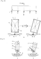
- Fig. 13 shows the torsion structure where Fig. 13a is an elevation view, and Fig. 13b is a view as seen from and along arrow A, Fig. 13b1 is the torsion structure before deformation, and Fig. 13b2 is the torsion structure after deformation.
- L denotes the span of the torsion structure.
- 11 denotes a thin wall closed cross-section
- 12 denotes a sectional restriction point (the rotation axle of the axle type support 100).
- Solid lines at both ends of the support span and dotted lines sandwiched by the solid lines in the elevation view 13a correspond to the locations of the thin wall closed cross-section 11, and the sectional restriction point 12 indicates a restriction point for in-plane displacement of the nearest cross-section.
- Fig. 13b1 Dotted lines in Fig. 13b1 show the cross-sectional shapes at the location of the thin wall closed cross-section 11 of the torsion structure before deformation. Each cross-section is in an upright position since there is no deformation due to applied load.
- Dotted lines in Fig. 13b2 show the cross-sectional shapes at the location of the thin wall closed cross-section 11 of the torsion structure after deformation. Each cross-section rotates around the sectional restriction point 12, and the thin wall closed cross-section 11 is in a twisting deformation state. Both ends of the torsion structure 1 have no deformation since they are in a fixed state.
- Fig. 14 shows details of the thin wall closed cross-section 11 and the sectional restriction point 12 of Fig. 13 . Parts that are the same or equivalent to those of Fig. 13 are given the same reference numerals and explanation thereof is omitted (the same holds true hereafter).
- Fig. 14a is an elevation view and Fig. 14b is a cross-section of a view as seen from and along arrow A.
- Fig. 14b1 shows a state before deformation
- Fig. 14b2 shows a state after deformation.
- torsion structure 13 denotes a cross-section of a member (it may be written as "thin wall” hereafter) composing the torsion structure 1.
- the thin wall closed cross-section 11 is in an upright position as shown in Fig. 14b1 when there is no deformation due to applied load.
- the thin wall closed cross-section 11 is composed by the thin wall 13, which is continuous and closed.
- the torsion structure 1 is deformed as shown in Fig. 14b2 due to an applied load.
- the thin wall closed cross-section 11 has rotated around the sectional restriction point 12.
- the sectional restriction point 12 restricts the in-plane parallel displacement of the cross-section shown in the figure but does not restrict the rotation of the cross-section.
- the torsion structure according to this Specification is characterized by the thin wall closed cross-section 11 composed by the thin wall 13 that is continuous and closed and the sectional restriction point 12 that restricts in-plane parallel displacement of the cross-section.
- the axle type support 100 of Embodiment 1 is described according to Fig. 15 through Fig. 17 .
- 14 denotes a rail
- 15 denotes a rail head circular arc
- 16 denotes a rail head center
- 17 denotes a roller
- 18 denotes a roller center line
- 19 denotes a roller axle center
- 20 denotes a roller tread circular arc.
- the head of the rail 14 supported by the rail foundation 4 is the circular arc 15 around the rail head center 16.
- the tread surface of the roller 17 is the circular arc 20 with a corresponding radius to radius of the rail head circular arc 15.
- the roller 17 is fixed to the gate leaf 1 (torsion structure 1) through the axle center 19 thereof.
- the "corresponding radius” means a radius that has proper difference between the roller tread and the rail head.
- Fig. 15a shows a state before deformation and Fig. 15b shows a state after deformation.
- Fig. 15b shows that the gate leaf 1 is twisted and deformed due to an applied load and rotated around rail head center 16.
- 21 denote a roller load and 22 denotes a contact surface between the roller 17 and the rail 14.
- Contact portions with the roller 17 and the rail 14 deform elastically and compose the contact surface 22.
- a free twisting deformation of the gate leaf 1 (corresponding to previously mentioned “(1.1) Free twisting deformation” of Problem 1) is possible without any additional bending deformation since the roller 17 rotates around the rail head center 16 and linearity of the twisting center line of the structure is maintained.
- roller load 21 will surely be transmitted to the rail 14 through the contact surface 22 since the roller load is directed at the rail head center 16 (corresponding to previously mentioned “(1.2) Water pressure support while the gate is completely closed” of Problem 1).
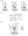
- Fig. 16 23 denotes a tangent line to the contact surface 22.
- ⁇ denotes an angle between the roller center line 18 and the roller load 21.
- Fig. 16a shows the case where ⁇ is 0 degrees
- Fig. 16b shows the case where ⁇ is 45 degrees
- Fig. 16c shows the case where ⁇ is 90 degrees.
- a rotational plane of the roller 17 including the center of the contact surface 22 is parallel to the cross-section including the roller center line 18 and the rail head center 16.
- Friction force roller load ⁇ cos 90 ⁇ ⁇ ⁇ friction coefficient of contact surface
- Off ⁇ running prevention force roller load ⁇ sin 90 ⁇ ⁇
- Fig. 17 is a result of a preliminary calculation by Formulas (1) and (2) in the cases of Fig. 16a through Fig. 16c where the roller load is 1000 tf and the frictional coefficient of the contact surface is 1.
- Embodiment 2 is explained while referencing Fig. 18 .
- 25 denotes load during gate movement.
- a plurality of the roller 17 (two) is provided. They are arranged so as to sandwich the head region 15 of the rail 14. They face in different directions from each other.
- the axle centers 19 of the respective rollers 17 are fixed on the gate leaf 1.
- Fig. 18b shows a relationship between load during gate movement 25 and roller load 21 that are in equilibrium.
- Fig. 19a shows a condition where the rail foundation 4 has no uneven settlement
- Fig. 19b shows a condition where the rail foundation 4 has a concave deformation due to its uneven settlement.
- Fig. 19c shows how the gate leaf 1 that is divided into two blocks work on the uneven settlement.
- a plurality of the roller 17 normally stays on the rail 14 but some of them lift up off from the rail due to the uneven settlement. They are shown by blank rollers in the figure.
- the gate leaf 1 be divided lengthwise into so many number of leaf blocks such that following capacity to the uneven settlement of the roller is improved.
- two of the roller 17 located at both ends of each block stay on the rail 14 and their load becomes less than in the case of Fig. 19b where there is a concave deformation due to uneven settlement (The load in this case increases to about 2.5 times, which is half of that in Fig. 19b .)
- a suitable division number should be selected according to anticipated amount of uneven settlement, number of rollers, roller strength etc., which are conditions concerning safety of a roller. This can prevent a roller from losing its function due to uneven settlement.
- the smallest division number is desired since gate leaf division is a cause of structural cost increase.
- Fig. 20 is an explanatory drawing for a coupling that joins divided blocks of the gate leaf 1 and transmits torsion moment from a block to the next block.
- Fig. 20a is an elevation view
- Fig. 20b is a cross-section as viewed from and along arrow A
- Fig. 20c is a cross-section as viewed from and along arrow B.
- 26 denotes a divided face
- 27 denotes a torsion moment transmission bar
- 28 denotes a torsion moment receiving hole
- 29 denotes a coupling force
- the torsion moment transmission bar 27 is fixed to a gate leaf 1R on the right side of the divided face 26.
- the tip thereof fits a gate leaf 1L on the left side of the divided face 26.
- Torsion moment of the gate leaf 1R on the right side of the divided face 26 is transmitted to the gate leaf 1L on the left side of the divided face 26 through the torsion moment transmission bar 27.
- the tip of the torsion moment transmission bar 27 and the torsion moment receiving hole 28 have fit each other well.
- the torsion moment is transmitted in the form of a coupling force 29 from the tip of the torsion moment transmission bar to a sidewall of the torsion moment receiving hole 28.
- the torsion moment transmission bar 27 and the torsion moment receiving hole 28 move differently in order to follow uneven settlement of the rail foundation14.
- the torsion moment receiving hole 28 is made to be a vertically long hole. It should be long enough so that the tip of the torsion moment transmission bar 27 and the torsion moment receiving hole 28 fit together well.
- the transmission is generally carried out in the form of a coupling force.
- the maintaining method depends upon pulling type, push type, self-propelling type etc., which are well-known lateral movement methods. Number of division is arbitrary but fewer is cost effective.
- Fig. 21 shows an s coordinate that is necessary for explaining a result of the warping alleviation method. Parts that are the same or equivalent to those already shown are given the same reference numerals and explanation thereof is omitted.
- 30 denotes an s coordinate set along a center line of the thin wall closed cross-section 11
- 31 denotes a positive direction of the s coordinate
- 32 denotes a shearing center of the thin wall closed cross-section 11.
- ds denotes a small distance on the s coordinate 30.
- t denotes thickness of the thin wall at ds
- 35 denotes a tangent line of ds
- rs denotes the length of a normal from the shearing center 32 to the tangent line 35.
- Warping of the thin wall closed cross-section 11 is expressed by function ⁇ of Formula (3).
- Formula (3) denotes area of the thin wall closed cross-section 11.
- ⁇ 0 warping constant
- Formula (4) Integration of Formula (3) and Formula (4) is executed on the s coordinate 30.
- t denotes "thickness at an arbitrary point on the thin wall closed cross-section.”
- rs denotes "the length of a normal from the shearing center of thin wall closed cross-section to the tangent line at the point.”
- Both and ⁇ 0 are zero when Formula (5) is substituted for Formula (3) and Formula (4) and integration of these formulas is executed.
- a warp of the cross-section is zero as long as the warping function ⁇ and the warping constant ⁇ 0 are zero, vertical stress proportional to the warp is also zero, and bending-torsion shearing stress in equilibrium with the vertical stress is also zero. In short, alleviation of bending torsion is realized (Problem 3).
- Fig. 22 shows a rectangular thin wall closed cross-section, and the right side of the figure shows its scantlings. Parts that are the same or equivalent to those already shown are given the same reference numerals and explanation thereof is omitted.
- Lf denotes half of flange width
- Lw denotes half of web height
- tf denotes thickness of the flange
- tw denotes thickness of the web.
- Formula (5) on the zero-warp condition becomes Formula (6) since the shearing center 32 coincides with the center of the figure.
- tf tw ⁇ Lw ⁇ Lf
- tf is approximately 12.4 mm when calculated by Formula (6) based on Lf, Lw and tw shown on the right side of Fig. 22 .
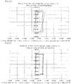
- Fig. 23 through Fig. 26 show the calculation results from the warping function ⁇ and bending-torsion shear flow when tf is changed between 34 mm and 12.4 mm.
- tf is 34 mm in Fig. 23
- tf is 16 mm in Fig. 24
- tf is 14 mm in Fig. 25
- tf is 12.4 mm in Fig. 26 .
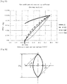
- Fig. 27 shows in percentages, when the resulting value when tf is 34 is set as 100, the calculations results of warping constant ⁇ 0, bending-torsion shear flow constant qw0, bending-torsion cross-section coefficient Cbd, and torsion cross-section coefficient Jt calculated when tf has decreased from 34 mm to 12.4 mm by 1 mm at a time.
- the lateral axis of the figure gives tf.
- Jt may be compensated by change in the closed cross-sectional form.
- cut in gate weight is possible by increasing Lf. While theoretical gate weight becomes minimal when zero-warp condition is achieved, an object of warping reduction in optimum design is cost reduction.
- cost component factors include material, fabrication, transportation, site construction, maintenance, operation etc.
- the minimum gate weight does not necessarily mean the minimum cost. For instance, there is an option that a high tensile steel plate having a custom-ordered thickness is fit in the stress increased zone so as to keep the minimum gate weight. However, it may be a better idea in terms of cost to increase the gate weight so as to maintain the material strength since the cost of material and fabrication rises.
- Fig. 28 shows a lens type thin wall closed cross-section.
- Hg denotes lens gate height
- r denotes thin wall radius
- ⁇ denotes thin wall angle
- t denotes thin wall thickness
- s denotes shearing center
- i and o both denote the center of the thin wall radius r.
- Formula (5) of the zero-warp condition can be converted to Formula (7).
- ⁇ ⁇ r ⁇ L s , i ⁇ r ⁇ L s , i ⁇ cos ⁇
- ⁇ ( ⁇ ) denotes a ratio of thickness for the zero-warp condition to the thin wall thickness.
- ⁇ denotes an angle between the thin wall radius r and a line segment oi, and 0 ⁇ ⁇ ⁇ ⁇ .
- L (s, i) denotes a line segment si.
- Fig. 29 shows the warping function and the bending-torsion shear flow of the lens type thin wall cross-section of Fig. 28 .
- Distribution of warping magnitude and vertical stress is proportional to the warping function, and distribution of bending-torsion shearing stress is proportional to the graph of the bending-torsion shear flow.
- Fig. 30 shows thickness calculated by Formula (7) at 11 ⁇ points on the lens type thin wall cross-section. Bending torsion on the lens type thin wall cross-section having the thickness as in Fig. 30 is eliminated and the shear flow and the warping of Fig. 29 disappear (Problem 3).
Landscapes
- Engineering & Computer Science (AREA)
- General Engineering & Computer Science (AREA)
- Structural Engineering (AREA)
- Mechanical Engineering (AREA)
- Civil Engineering (AREA)
- Barrages (AREA)
Claims (6)
- Vantelle d'écluse prévue pour passer au-dessus d'une écluse pour un écoulement d'eau ou des bateaux, ladite vantelle comprenant :une structure de torsion (1) qui comprend une section transversale fermée formée par une paroi fine fournie dans une direction coupant l'écluse, et qui est construite de manière à tourner dans la section transversale fermée autour d'un point de restriction de la section transversale fermée, dans laquelle un moment de torsion composé d'une charge appliquée et d'une force de réaction au niveau du point de restriction est transmis à un terminal de la structure en raison d'une rigidité de torsion ;un rail (14) fourni dans une direction coupant l'écluse ; etde multiples supports de type axe (100) qui fonctionnent en tant que point de restriction et se déplacent le long du rail (14) ; dans laquelle les supports du type axe sont de multiples rouleaux (17),caractérisée en ce quela forme de section transversale de la région de la tête (15) du rail (14) est un arc circulaire convexe,le plan de rotation de chacun des multiples rouleaux (17) incluant le centre de la surface de contact (22) est parallèle à la section transversale incluant la ligne centrale de rouleaux (18) et le centre de la tête de rail (16), etla forme de section transversale de la surface de roulement du rouleau (17) est un arc circulaire concave dont un rayon correspond au rayon de l'arc circulaire convexe de la région de la tête (15) du rail (14),dans laquelle une torsion libre de la structure de torsion (1) est possible sans aucune déformation de flexion additionnelle.
- Vantelle d'écluse prévue pour passer au-dessus d'une écluse pour un écoulement d'eau ou des bateaux, ladite vantelle comprenant :une structure de torsion (1) qui comprend une section transversale fermée formée par une paroi fine fournie dans une direction coupant l'écluse, et qui est construite de manière à tourner dans la section transversale fermée autour d'un point de restriction de la section transversale fermée, dans laquelle un moment de torsion composé d'une charge appliquée et d'une force de réaction au niveau du point de restriction est transmis à un terminal de la structure en raison d'une rigidité de torsion ;un rail (14) fourni dans une direction coupant l'écluse ; etde multiples supports du type axe (100) qui fonctionnent en tant que point de restriction et se déplacent le long du rail (14) ; dans laquelle les supports de type axe sont de multiples rouleaux (17), caractérisée en ce quela forme de section transversale de la région de la tête (15) du rail (14) est un arc circulaire convexe,le plan de rotation de chacun des multiples rouleaux (17) incluant le centre de la surface de contact (22) est parallèle à la section transversale incluant la ligne centrale de rouleaux (18) et le centre de la tête de rail (16),dans laquelle les multiples rouleaux (17) sont agencés de manière à prendre en sandwich la région de la tête (15) du rail (14),et dans laquelle la vantelle peut se déplacer latéralement sans que les rouleaux (17) sortent des rails.
- Vantelle selon soit la revendication 1, soit la revendication 2, dans laquelle le produit d'une épaisseur t au niveau d'un point arbitraire sur la section transversale fermée de la structure de torsion (1) et une longueur rs d'une normale du centre de cisaillement de la section transversale fermée et de la ligne tangente au niveau du point est défini en tant que constante ou presque, de manière à rester à l'intérieur d'une plage prédéterminée.
- Vantelle selon l'une des revendications 1 ou 2, dans laquelle la section transversale fermée de la structure de torsion (1) est rectangulaire, et
tf est définie plus grande que tw x Lw ÷ Lf et plus petite que tw, où Lf représente une moitié d'une largeur de bride de la section transversale fermée rectangulaire, Lw représente une moitié de hauteur de bande, tf représente une épaisseur de bride, et tw représente une épaisseur de bande. - Vantelle selon l'une des revendications 1 ou 2, dans laquelle la section transversale fermée de la structure de torsion (1) est en forme de lentille convexe, et
la section transversale fermée avec la forme de lentille convexe est plus fine vers une extrémité conformément à un rapport η(α) d'épaisseur, où le rapport η(α) d'épaisseur est trouvé par la formule :
- Vantelle selon l'une quelconque des revendications 1 à 5, dans laquelle la structure de torsion (1) est divisée en une première portion bloquant une partie de l'écluse et en une seconde portion bloquant au moins une partie d'une autre portion de l'écluse, et la première portion et la seconde portion sont liées par un couplage qui transmet un moment de torsion.
Applications Claiming Priority (1)
| Application Number | Priority Date | Filing Date | Title |
|---|---|---|---|
| PCT/JP2012/072416 WO2014037987A1 (fr) | 2012-09-04 | 2012-09-04 | Écluse |
Publications (3)
| Publication Number | Publication Date |
|---|---|
| EP2894259A1 EP2894259A1 (fr) | 2015-07-15 |
| EP2894259A4 EP2894259A4 (fr) | 2016-08-03 |
| EP2894259B1 true EP2894259B1 (fr) | 2018-02-07 |
Family
ID=50236641
Family Applications (1)
| Application Number | Title | Priority Date | Filing Date |
|---|---|---|---|
| EP12884150.9A Not-in-force EP2894259B1 (fr) | 2012-09-04 | 2012-09-04 | Écluse |
Country Status (5)
| Country | Link |
|---|---|
| US (1) | US9783946B2 (fr) |
| EP (1) | EP2894259B1 (fr) |
| JP (1) | JP5979797B2 (fr) |
| CN (1) | CN104603365B (fr) |
| WO (1) | WO2014037987A1 (fr) |
Families Citing this family (5)
| Publication number | Priority date | Publication date | Assignee | Title |
|---|---|---|---|---|
| US9400085B2 (en) * | 2012-12-19 | 2016-07-26 | Jon Erik Rasmussen | Method, system, and apparatus for flood control |
| JP6472104B2 (ja) | 2015-09-25 | 2019-02-20 | 溥 寺田 | 水門 |
| JP6629457B2 (ja) * | 2016-08-22 | 2020-01-15 | 溥 寺田 | 水門 |
| DK179294B1 (da) * | 2017-03-30 | 2018-04-16 | Steen Olsen Invest Aps | Stormflodssikring |
| CN107503328A (zh) * | 2017-09-25 | 2017-12-22 | 芜湖市银鸿液压件有限公司 | 一种道口闸双向推送机构 |
Family Cites Families (14)
| Publication number | Priority date | Publication date | Assignee | Title |
|---|---|---|---|---|
| FR1195157A (fr) * | 1958-04-29 | 1959-11-16 | Bouchure réversible de formes de radoub, cales sèches et autres | |
| JPS5214354Y2 (fr) * | 1972-06-12 | 1977-03-31 | ||
| JPS4928641A (fr) | 1972-07-14 | 1974-03-14 | ||
| JPS533880B2 (fr) * | 1973-06-15 | 1978-02-10 | ||
| JPS53141055U (fr) * | 1977-04-14 | 1978-11-08 | ||
| JPS53141055A (en) | 1977-05-14 | 1978-12-08 | Nippon Jikuuke Kensa Kiyoukai | Mandrel with flange for measurement of rotation accuracy of rolling bearing |
| JPS58181979A (ja) * | 1982-04-20 | 1983-10-24 | 西田鉄工株式会社 | 回転式ガイドレ−ル装置 |
| FR2705636B1 (fr) * | 1993-05-26 | 1995-07-07 | Lohr Ind | Ensemble de guidage directionnel d'un véhicule routier le long d'un rail. |
| CN2217641Y (zh) * | 1994-05-07 | 1996-01-17 | 洪国材 | 自动倒卧堰 |
| CN2323014Y (zh) * | 1996-08-27 | 1999-06-09 | 石建初 | 一种玻璃钢闸门 |
| JP3843879B2 (ja) * | 2002-04-09 | 2006-11-08 | 石川島播磨重工業株式会社 | 横引きゲート |
| JP3890527B2 (ja) * | 2002-05-31 | 2007-03-07 | 清水建設株式会社 | 水門 |
| JP2006002552A (ja) * | 2004-06-18 | 2006-01-05 | Terauchi Bussan Kk | 防潮堤における防潮扉の緊急閉門装置 |
| JP4310334B2 (ja) * | 2006-12-15 | 2009-08-05 | 株式会社日本ピット | 引戸式防水装置 |
-
2012
- 2012-09-04 CN CN201280075626.8A patent/CN104603365B/zh not_active Expired - Fee Related
- 2012-09-04 US US14/423,008 patent/US9783946B2/en not_active Expired - Fee Related
- 2012-09-04 EP EP12884150.9A patent/EP2894259B1/fr not_active Not-in-force
- 2012-09-04 JP JP2014534057A patent/JP5979797B2/ja active Active
- 2012-09-04 WO PCT/JP2012/072416 patent/WO2014037987A1/fr active Application Filing
Non-Patent Citations (1)
| Title |
|---|
| None * |
Also Published As
| Publication number | Publication date |
|---|---|
| EP2894259A4 (fr) | 2016-08-03 |
| WO2014037987A1 (fr) | 2014-03-13 |
| CN104603365A (zh) | 2015-05-06 |
| US20150218767A1 (en) | 2015-08-06 |
| CN104603365B (zh) | 2017-04-12 |
| US9783946B2 (en) | 2017-10-10 |
| EP2894259A1 (fr) | 2015-07-15 |
| JPWO2014037987A1 (ja) | 2016-08-08 |
| JP5979797B2 (ja) | 2016-08-31 |
Similar Documents
| Publication | Publication Date | Title |
|---|---|---|
| US9970170B2 (en) | Sluice gate | |
| EP2894259B1 (fr) | Écluse | |
| Lewin | Hydraulic gates and valves: In free surface flow and submerged outlets | |
| US10612204B2 (en) | Sluice gate | |
| CN101949142A (zh) | 一种离岸高桩码头长分段结构 | |
| CN208413047U (zh) | 云型轨道 | |
| JP4309912B2 (ja) | ローラゲート | |
| CN209798507U (zh) | 一种布置在水电站闸坝上的门机交通桥 | |
| CN218712716U (zh) | 一种弧形闸门启闭装置 | |
| CN108674908A (zh) | 云型轨道 | |
| CN219670960U (zh) | 一种基于导轨式胶轮系统的轨道梁 | |
| CN217054027U (zh) | 一种蜂窝梁 | |
| CN219410757U (zh) | 一种具有排水装置的浮箱闸门 | |
| CN213571546U (zh) | 方管钢桁梁空间索面斜拉桥索梁锚固结构 | |
| Becker | Development of the Chicago type bascule bridge | |
| KR100588446B1 (ko) | 교량의 연속교화 구조 및 그 시공방법 | |
| KR20040041557A (ko) | 상부 플렌지와 하부 플렌지의 두께 또는 폭이 다른 이형플렌지 에이치형강 | |
| WO2023151761A1 (fr) | Dispositif de connexion d'un navire à un réseau d'alimentation côté terre | |
| CN116005570A (zh) | 一种主塔内穿式钢箱梁缆索承重桥梁过塔施工方法 | |
| CN117513257A (zh) | 一种卷扬机驱动的中枢旋转闸门 | |
| CN113981802A (zh) | 一种可快速启闭浮桥的建造方法与使用方法 | |
| Anderson et al. | DISCUSSION. FORTH ROAD BRIDGE. | |
| Abrahams et al. | Bridge Engineering Handbook. Ed. Wai-Fah Chen and Lian Duan Boca Raton: CRC Press, 2000 | |
| CORPS OF ENGINEERS WASHINGTON DC | Structural Design of Closure Structures for Local Flood Protection Projects | |
| JPH068426U (ja) | 浮桟橋のガイド機構 |
Legal Events
| Date | Code | Title | Description |
|---|---|---|---|
| PUAI | Public reference made under article 153(3) epc to a published international application that has entered the european phase |
Free format text: ORIGINAL CODE: 0009012 |
|
| 17P | Request for examination filed |
Effective date: 20150324 |
|
| AK | Designated contracting states |
Kind code of ref document: A1 Designated state(s): AL AT BE BG CH CY CZ DE DK EE ES FI FR GB GR HR HU IE IS IT LI LT LU LV MC MK MT NL NO PL PT RO RS SE SI SK SM TR |
|
| AX | Request for extension of the european patent |
Extension state: BA ME |
|
| DAX | Request for extension of the european patent (deleted) | ||
| RA4 | Supplementary search report drawn up and despatched (corrected) |
Effective date: 20160630 |
|
| RIC1 | Information provided on ipc code assigned before grant |
Ipc: E02B 7/40 20060101AFI20160624BHEP Ipc: E02B 7/20 20060101ALI20160624BHEP |
|
| 17Q | First examination report despatched |
Effective date: 20170210 |
|
| GRAP | Despatch of communication of intention to grant a patent |
Free format text: ORIGINAL CODE: EPIDOSNIGR1 |
|
| INTG | Intention to grant announced |
Effective date: 20170920 |
|
| GRAS | Grant fee paid |
Free format text: ORIGINAL CODE: EPIDOSNIGR3 |
|
| GRAA | (expected) grant |
Free format text: ORIGINAL CODE: 0009210 |
|
| AK | Designated contracting states |
Kind code of ref document: B1 Designated state(s): AL AT BE BG CH CY CZ DE DK EE ES FI FR GB GR HR HU IE IS IT LI LT LU LV MC MK MT NL NO PL PT RO RS SE SI SK SM TR |
|
| REG | Reference to a national code |
Ref country code: GB Ref legal event code: FG4D |
|
| REG | Reference to a national code |
Ref country code: AT Ref legal event code: REF Ref document number: 968860 Country of ref document: AT Kind code of ref document: T Effective date: 20180215 Ref country code: CH Ref legal event code: EP |
|
| REG | Reference to a national code |
Ref country code: IE Ref legal event code: FG4D |
|
| REG | Reference to a national code |
Ref country code: DE Ref legal event code: R096 Ref document number: 602012042719 Country of ref document: DE |
|
| REG | Reference to a national code |
Ref country code: NL Ref legal event code: FP |
|
| REG | Reference to a national code |
Ref country code: AT Ref legal event code: MK05 Ref document number: 968860 Country of ref document: AT Kind code of ref document: T Effective date: 20180207 |
|
| PG25 | Lapsed in a contracting state [announced via postgrant information from national office to epo] |
Ref country code: LT Free format text: LAPSE BECAUSE OF FAILURE TO SUBMIT A TRANSLATION OF THE DESCRIPTION OR TO PAY THE FEE WITHIN THE PRESCRIBED TIME-LIMIT Effective date: 20180207 Ref country code: HR Free format text: LAPSE BECAUSE OF FAILURE TO SUBMIT A TRANSLATION OF THE DESCRIPTION OR TO PAY THE FEE WITHIN THE PRESCRIBED TIME-LIMIT Effective date: 20180207 Ref country code: ES Free format text: LAPSE BECAUSE OF FAILURE TO SUBMIT A TRANSLATION OF THE DESCRIPTION OR TO PAY THE FEE WITHIN THE PRESCRIBED TIME-LIMIT Effective date: 20180207 Ref country code: FI Free format text: LAPSE BECAUSE OF FAILURE TO SUBMIT A TRANSLATION OF THE DESCRIPTION OR TO PAY THE FEE WITHIN THE PRESCRIBED TIME-LIMIT Effective date: 20180207 Ref country code: NO Free format text: LAPSE BECAUSE OF FAILURE TO SUBMIT A TRANSLATION OF THE DESCRIPTION OR TO PAY THE FEE WITHIN THE PRESCRIBED TIME-LIMIT Effective date: 20180507 Ref country code: CY Free format text: LAPSE BECAUSE OF FAILURE TO SUBMIT A TRANSLATION OF THE DESCRIPTION OR TO PAY THE FEE WITHIN THE PRESCRIBED TIME-LIMIT Effective date: 20180207 |
|
| PG25 | Lapsed in a contracting state [announced via postgrant information from national office to epo] |
Ref country code: SE Free format text: LAPSE BECAUSE OF FAILURE TO SUBMIT A TRANSLATION OF THE DESCRIPTION OR TO PAY THE FEE WITHIN THE PRESCRIBED TIME-LIMIT Effective date: 20180207 Ref country code: LV Free format text: LAPSE BECAUSE OF FAILURE TO SUBMIT A TRANSLATION OF THE DESCRIPTION OR TO PAY THE FEE WITHIN THE PRESCRIBED TIME-LIMIT Effective date: 20180207 Ref country code: PL Free format text: LAPSE BECAUSE OF FAILURE TO SUBMIT A TRANSLATION OF THE DESCRIPTION OR TO PAY THE FEE WITHIN THE PRESCRIBED TIME-LIMIT Effective date: 20180207 Ref country code: BG Free format text: LAPSE BECAUSE OF FAILURE TO SUBMIT A TRANSLATION OF THE DESCRIPTION OR TO PAY THE FEE WITHIN THE PRESCRIBED TIME-LIMIT Effective date: 20180507 Ref country code: GR Free format text: LAPSE BECAUSE OF FAILURE TO SUBMIT A TRANSLATION OF THE DESCRIPTION OR TO PAY THE FEE WITHIN THE PRESCRIBED TIME-LIMIT Effective date: 20180508 Ref country code: IS Free format text: LAPSE BECAUSE OF FAILURE TO SUBMIT A TRANSLATION OF THE DESCRIPTION OR TO PAY THE FEE WITHIN THE PRESCRIBED TIME-LIMIT Effective date: 20180607 Ref country code: RS Free format text: LAPSE BECAUSE OF FAILURE TO SUBMIT A TRANSLATION OF THE DESCRIPTION OR TO PAY THE FEE WITHIN THE PRESCRIBED TIME-LIMIT Effective date: 20180207 Ref country code: AT Free format text: LAPSE BECAUSE OF FAILURE TO SUBMIT A TRANSLATION OF THE DESCRIPTION OR TO PAY THE FEE WITHIN THE PRESCRIBED TIME-LIMIT Effective date: 20180207 |
|
| REG | Reference to a national code |
Ref country code: FR Ref legal event code: PLFP Year of fee payment: 7 |
|
| PG25 | Lapsed in a contracting state [announced via postgrant information from national office to epo] |
Ref country code: IT Free format text: LAPSE BECAUSE OF FAILURE TO SUBMIT A TRANSLATION OF THE DESCRIPTION OR TO PAY THE FEE WITHIN THE PRESCRIBED TIME-LIMIT Effective date: 20180207 Ref country code: AL Free format text: LAPSE BECAUSE OF FAILURE TO SUBMIT A TRANSLATION OF THE DESCRIPTION OR TO PAY THE FEE WITHIN THE PRESCRIBED TIME-LIMIT Effective date: 20180207 Ref country code: EE Free format text: LAPSE BECAUSE OF FAILURE TO SUBMIT A TRANSLATION OF THE DESCRIPTION OR TO PAY THE FEE WITHIN THE PRESCRIBED TIME-LIMIT Effective date: 20180207 Ref country code: RO Free format text: LAPSE BECAUSE OF FAILURE TO SUBMIT A TRANSLATION OF THE DESCRIPTION OR TO PAY THE FEE WITHIN THE PRESCRIBED TIME-LIMIT Effective date: 20180207 |
|
| REG | Reference to a national code |
Ref country code: DE Ref legal event code: R097 Ref document number: 602012042719 Country of ref document: DE |
|
| PG25 | Lapsed in a contracting state [announced via postgrant information from national office to epo] |
Ref country code: DK Free format text: LAPSE BECAUSE OF FAILURE TO SUBMIT A TRANSLATION OF THE DESCRIPTION OR TO PAY THE FEE WITHIN THE PRESCRIBED TIME-LIMIT Effective date: 20180207 Ref country code: SM Free format text: LAPSE BECAUSE OF FAILURE TO SUBMIT A TRANSLATION OF THE DESCRIPTION OR TO PAY THE FEE WITHIN THE PRESCRIBED TIME-LIMIT Effective date: 20180207 Ref country code: CZ Free format text: LAPSE BECAUSE OF FAILURE TO SUBMIT A TRANSLATION OF THE DESCRIPTION OR TO PAY THE FEE WITHIN THE PRESCRIBED TIME-LIMIT Effective date: 20180207 Ref country code: SK Free format text: LAPSE BECAUSE OF FAILURE TO SUBMIT A TRANSLATION OF THE DESCRIPTION OR TO PAY THE FEE WITHIN THE PRESCRIBED TIME-LIMIT Effective date: 20180207 |
|
| PLBE | No opposition filed within time limit |
Free format text: ORIGINAL CODE: 0009261 |
|
| STAA | Information on the status of an ep patent application or granted ep patent |
Free format text: STATUS: NO OPPOSITION FILED WITHIN TIME LIMIT |
|
| 26N | No opposition filed |
Effective date: 20181108 |
|
| PG25 | Lapsed in a contracting state [announced via postgrant information from national office to epo] |
Ref country code: SI Free format text: LAPSE BECAUSE OF FAILURE TO SUBMIT A TRANSLATION OF THE DESCRIPTION OR TO PAY THE FEE WITHIN THE PRESCRIBED TIME-LIMIT Effective date: 20180207 |
|
| PG25 | Lapsed in a contracting state [announced via postgrant information from national office to epo] |
Ref country code: MC Free format text: LAPSE BECAUSE OF FAILURE TO SUBMIT A TRANSLATION OF THE DESCRIPTION OR TO PAY THE FEE WITHIN THE PRESCRIBED TIME-LIMIT Effective date: 20180207 |
|
| REG | Reference to a national code |
Ref country code: CH Ref legal event code: PL |
|
| REG | Reference to a national code |
Ref country code: IE Ref legal event code: MM4A |
|
| PG25 | Lapsed in a contracting state [announced via postgrant information from national office to epo] |
Ref country code: LU Free format text: LAPSE BECAUSE OF NON-PAYMENT OF DUE FEES Effective date: 20180904 |
|
| PG25 | Lapsed in a contracting state [announced via postgrant information from national office to epo] |
Ref country code: IE Free format text: LAPSE BECAUSE OF NON-PAYMENT OF DUE FEES Effective date: 20180904 |
|
| PG25 | Lapsed in a contracting state [announced via postgrant information from national office to epo] |
Ref country code: CH Free format text: LAPSE BECAUSE OF NON-PAYMENT OF DUE FEES Effective date: 20180930 Ref country code: LI Free format text: LAPSE BECAUSE OF NON-PAYMENT OF DUE FEES Effective date: 20180930 |
|
| PG25 | Lapsed in a contracting state [announced via postgrant information from national office to epo] |
Ref country code: MT Free format text: LAPSE BECAUSE OF NON-PAYMENT OF DUE FEES Effective date: 20180904 |
|
| PG25 | Lapsed in a contracting state [announced via postgrant information from national office to epo] |
Ref country code: TR Free format text: LAPSE BECAUSE OF FAILURE TO SUBMIT A TRANSLATION OF THE DESCRIPTION OR TO PAY THE FEE WITHIN THE PRESCRIBED TIME-LIMIT Effective date: 20180207 |
|
| PG25 | Lapsed in a contracting state [announced via postgrant information from national office to epo] |
Ref country code: PT Free format text: LAPSE BECAUSE OF FAILURE TO SUBMIT A TRANSLATION OF THE DESCRIPTION OR TO PAY THE FEE WITHIN THE PRESCRIBED TIME-LIMIT Effective date: 20180207 |
|
| PG25 | Lapsed in a contracting state [announced via postgrant information from national office to epo] |
Ref country code: MK Free format text: LAPSE BECAUSE OF NON-PAYMENT OF DUE FEES Effective date: 20180207 Ref country code: HU Free format text: LAPSE BECAUSE OF FAILURE TO SUBMIT A TRANSLATION OF THE DESCRIPTION OR TO PAY THE FEE WITHIN THE PRESCRIBED TIME-LIMIT; INVALID AB INITIO Effective date: 20120904 |
|
| PGFP | Annual fee paid to national office [announced via postgrant information from national office to epo] |
Ref country code: NL Payment date: 20210924 Year of fee payment: 10 Ref country code: FR Payment date: 20210927 Year of fee payment: 10 |
|
| PGFP | Annual fee paid to national office [announced via postgrant information from national office to epo] |
Ref country code: GB Payment date: 20210924 Year of fee payment: 10 Ref country code: BE Payment date: 20210924 Year of fee payment: 10 Ref country code: DE Payment date: 20210930 Year of fee payment: 10 |
|
| REG | Reference to a national code |
Ref country code: DE Ref legal event code: R119 Ref document number: 602012042719 Country of ref document: DE |
|
| REG | Reference to a national code |
Ref country code: NL Ref legal event code: MM Effective date: 20221001 |
|
| GBPC | Gb: european patent ceased through non-payment of renewal fee |
Effective date: 20220904 |
|
| REG | Reference to a national code |
Ref country code: BE Ref legal event code: MM Effective date: 20220930 |
|
| PG25 | Lapsed in a contracting state [announced via postgrant information from national office to epo] |
Ref country code: NL Free format text: LAPSE BECAUSE OF NON-PAYMENT OF DUE FEES Effective date: 20221001 |
|
| PG25 | Lapsed in a contracting state [announced via postgrant information from national office to epo] |
Ref country code: FR Free format text: LAPSE BECAUSE OF NON-PAYMENT OF DUE FEES Effective date: 20220930 Ref country code: DE Free format text: LAPSE BECAUSE OF NON-PAYMENT OF DUE FEES Effective date: 20230401 |
|
| PG25 | Lapsed in a contracting state [announced via postgrant information from national office to epo] |
Ref country code: BE Free format text: LAPSE BECAUSE OF NON-PAYMENT OF DUE FEES Effective date: 20220930 |
|
| PG25 | Lapsed in a contracting state [announced via postgrant information from national office to epo] |
Ref country code: GB Free format text: LAPSE BECAUSE OF NON-PAYMENT OF DUE FEES Effective date: 20220904 |