EP2894059A1 - Einstellbare Kindersicherheitssitzanordnung - Google Patents
Einstellbare Kindersicherheitssitzanordnung Download PDFInfo
- Publication number
- EP2894059A1 EP2894059A1 EP15150479.2A EP15150479A EP2894059A1 EP 2894059 A1 EP2894059 A1 EP 2894059A1 EP 15150479 A EP15150479 A EP 15150479A EP 2894059 A1 EP2894059 A1 EP 2894059A1
- Authority
- EP
- European Patent Office
- Prior art keywords
- seat
- base
- sliding element
- child safety
- seat assembly
- Prior art date
- Legal status (The legal status is an assumption and is not a legal conclusion. Google has not performed a legal analysis and makes no representation as to the accuracy of the status listed.)
- Granted
Links
- 230000007246 mechanism Effects 0.000 claims abstract description 35
- 230000000452 restraining effect Effects 0.000 claims description 13
- 238000010276 construction Methods 0.000 description 5
- 238000000926 separation method Methods 0.000 description 3
- 238000007792 addition Methods 0.000 description 2
- 230000008901 benefit Effects 0.000 description 2
- 230000000903 blocking effect Effects 0.000 description 2
- 238000004519 manufacturing process Methods 0.000 description 2
- 230000004048 modification Effects 0.000 description 2
- 238000012986 modification Methods 0.000 description 2
- 230000009471 action Effects 0.000 description 1
- 238000005452 bending Methods 0.000 description 1
- 238000006073 displacement reaction Methods 0.000 description 1
- 239000002991 molded plastic Substances 0.000 description 1
- 238000000465 moulding Methods 0.000 description 1
Images


Classifications
-
- B—PERFORMING OPERATIONS; TRANSPORTING
- B60—VEHICLES IN GENERAL
- B60N—SEATS SPECIALLY ADAPTED FOR VEHICLES; VEHICLE PASSENGER ACCOMMODATION NOT OTHERWISE PROVIDED FOR
- B60N2/00—Seats specially adapted for vehicles; Arrangement or mounting of seats in vehicles
- B60N2/24—Seats specially adapted for vehicles; Arrangement or mounting of seats in vehicles for particular purposes or particular vehicles
- B60N2/26—Seats specially adapted for vehicles; Arrangement or mounting of seats in vehicles for particular purposes or particular vehicles for children
- B60N2/28—Seats readily mountable on, and dismountable from, existing seats or other parts of the vehicle
- B60N2/2821—Seats readily mountable on, and dismountable from, existing seats or other parts of the vehicle having a seat and a base part
-
- B—PERFORMING OPERATIONS; TRANSPORTING
- B60—VEHICLES IN GENERAL
- B60N—SEATS SPECIALLY ADAPTED FOR VEHICLES; VEHICLE PASSENGER ACCOMMODATION NOT OTHERWISE PROVIDED FOR
- B60N2/00—Seats specially adapted for vehicles; Arrangement or mounting of seats in vehicles
- B60N2/24—Seats specially adapted for vehicles; Arrangement or mounting of seats in vehicles for particular purposes or particular vehicles
- B60N2/26—Seats specially adapted for vehicles; Arrangement or mounting of seats in vehicles for particular purposes or particular vehicles for children
- B60N2/28—Seats readily mountable on, and dismountable from, existing seats or other parts of the vehicle
- B60N2/2875—Seats readily mountable on, and dismountable from, existing seats or other parts of the vehicle inclinable, as a whole or partially
Definitions
- the present invention relates to a child safety seat assembly, and more particularly to a seat assembly having an adjustable seat portion.
- FIG. 1 is a schematic view illustrating a conventional automobile seat adjustment mechanism 1.
- the seat adjustment mechanism 1 includes a sliding piece 11 that can be guided in movement by guide posts 12 relative to the fixed base 14. While it slides lengthwise, the sliding piece 11 drives two opposite locking rods 15 to move along inclined slots 17. The sliding engagement between the locking rods 15 and the slots 17 causes each of the locking rods 15 to also shift laterally, such that a distal end of each locking rod 15 can disengage from corresponding recesses on the seat portion (not shown). The seat portion is thereby unlocked, and can be adjusted to a desired recline position.
- the lengthwise movement of the locking rods 15 guided by the slots 17 can result the distal ends of the locking rods 15 being urged in contact against the recesses on the seat portion, which increases movement resistance exerted on the locking rods 15 relative to the base 14.
- the operation for unlocking the seat portion may not be as smooth as desired.
- the mechanism 1 is relatively complex to assemble, increasing the fabrication cost.
- the present application describes an adjustable child safety seat assembly.
- the child safety seat assembly includes a base, a seat adjustable between a plurality of recline positions relative to the base, and a latch mechanism operable to detachably lock the seat on the base at any one of the reclined positions.
- the seat includes a seating portion, and a protruding portion projecting downward from a bottom of the seating portion.
- the latch mechanism includes a sliding element and at least one resilient arm. The sliding element is assembled with the seat, and is movable relative to the seat, the sliding element having a front end that is exposed outward at a front of the protruding portion and is accessible by a user for operation.
- the resilient arm is fixedly joined with the sliding element, and has a distal end provided with a latching portion.
- the sliding element is movable in a first direction to drive the resilient arm in movement and displace the latching portion in a second direction for locking the seat with the base.
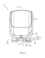
- FIGS. 2 , 3 and 4 are respectively perspective, exploded and front views illustrating one embodiment of an adjustable child safety seat assembly 2.
- the child safety seat assembly 2 comprises a seat 3, a base 4, and a latch mechanism 5 operable to lock the seat 3 with the base 4.
- the seat 3 and the base 4 can be configured as separate parts that can be detachably mounted with each other during use, or as two parts that are permanently joined with each other.
- the latch mechanism 5 can detachably lock the seat 3 at different adjustable reclined positions on the base 4.
- FIG. 5 is an exploded cross-sectional view taken along section line V shown in FIG. 4 .
- the seat 3 may be formed as a rigid shell comprising a seating portion 31, and two spaced-apart rail portions 32 protruding downward from a bottom of the seating portion 31.
- the rail portions 32 can be disposed parallel with each other at left and right sides, and respectively have a curved shape extending from a front toward a rear of the seating portion 31.
- each rail portion 32 may have an arc shape having a center of curvature O.
- a plurality of stop abutments 34 may be respectively provided at the front and rear end of each rail portion 32.
- a stop abutment 34 located at the front end of each rail portion 32 may be formed as a protrusion that extends from an inner side of each rail portion 32 and projects upward in an oblique direction.
- the stop abutment 34 located proximate the rear end of each rail portion 32 may be formed as a protrusion of the rail portion 32 that projects approximately in a radial direction toward the center of curvature O.
- the stop abutments 34 may be formed integrally with the rail portions 32, or as separate parts mounted in proximity of the rail portions 32.
- each rail portion 32 can also include a curved flange 33 protruding toward a central area of the seating portion 32, and a plurality of locking locations 35 above the flange 33.
- Each of the flanges 33 can extend lengthwise along the rail portion 32 with an arc shape similar to that of the rail portions 32 centered on the point O.
- the stop abutments 34 may be respectively provided at the front and rear ends of each flange 33.
- the locking locations 35 can include three first locking grooves 35a, and a remote second locking groove 35b.
- the rail portions 32 can be in sliding engagement with a matching structure provided on the base 4 for allowing adjustment of the seat 3 relative to the base 4, and the latch mechanism 5 can be operable to engage with any one of the locking locations 35 for locking the seat 3 in place on the base 4.
- the base 4 includes an upper casing 41 and a lower casing 42 that can be assembled together to delimit an inner space in which the latch mechanism 5 is assembled.
- An upper side of the upper casing 41 includes an upwardly raised portion 410 located at a central region, and two recessed portions 411 at left and right sides of the raised portion 410.
- the raised portion 410 has two opposite lateral sidewalls 410a respectively adjacent to the recessed portions 411.
- the recessed portions 411 are disposed parallel with each other along a lengthwise direction, and respectively have a shape adapted to receive the placement of the rail portions 32.
- Each lateral sidewall 410a of the raised portion 410 includes a curved guide slot 412, and an opening 413 located proximate to a front of the raised portion 410 and above the guide slot 412.
- the guide slot 412 and opening 413 are provided symmetrical on the two opposite lateral sidewalls 410a of the raised portion 410.
- Each of the guide slots 412 is located above a bottom surface of the adjacent recessed portion 411, separated from the bottom surface of the adjacent recessed portion 411 by a rim portion 414 forming a step shape.
- each of the guide slots 412 and recessed portions 411 can have a profile with a curvature that substantially matches with that of the rail portions 32 and flanges 33.
- the rail portions 32 When the seat 3 is assembled with the base 4, the rail portions 32 can be accommodated in the recessed portions 411, the raised portion 410 can be placed in a gap between the two rail portions 32, and the flanges 33 of the seat 3 can respectively engage through the guide slots 412 in a sliding manner. As the rail portions 32 and flanges 33 are respectively mounted movable relative to the recessed portions 411 and guide slots 412, the seat 3 can thereby perform adjusting movements along an arcuate path that is approximately centered on the point O.
- each guide slot 412 can have an enlarged opening 415, and end abutments 416 are respectively formed at the front and rear end of each guide slot 412.
- the end abutments 416 may be formed as shoulder portions, and one of the end abutments 416 can at least partially delimit a rim of the enlarged opening 415.
- the front and rear stop abutments 34 provided on the rail portions 32 can respectively come in contact and abut against the corresponding front and rear abutments 416 on the base 4 for respectively limiting forward and backward adjustment of the seat 3.
- FIG. 6 is a cross-sectional view taken along section line VI shown in FIG. 4 .
- the latch mechanism 5 can be assembled between the upper and lower casing 41 and 42 at a position upwardly enclosed by the raised portion 410, and downwardly enclosed by the lower casing 42.
- the latch mechanism 5 includes a sliding element 51 and a spring 6.
- the sliding element 51 can have two resilient arms 52 that are respectively joined with opposite lateral sides of the sliding element 51.
- the resilient arms 52 can extend from the rear toward the front and laterally bend away in opposite directions from a central region of the sliding element 51. Distal ends of the resilient arms 52 respectively form latching portions 53 through which the base 4 can lock with the seat 3.
- a rear of the sliding element 51 can include a slot 54 through which the sliding element 51 can be assembled on the lower casing 42 in a slidable manner.
- the sliding element 51 including the resilient arms 52 and latching portions 53, may be formed in a single body (e.g., molded plastics), the resilient arms 52 being deformable relative to the sliding element 51.
- an interior surface of the lower casing 42 facing the upper casing 41 can include a protruding portion 421 at a central region thereof.
- the sliding element 51 is mounted between the upper and lower casing 41 and 42 with the protruding portion 421 inserted through the slot 54 for achieving a sliding connection. Once assembled, the sliding element 51 can thereby slide back and forth relative to the base 4.
- the spring 6 is placed in proximity to the rear end of the sliding element 51, one end of the spring 6 being connected with the rear end of the sliding element 51, another end of the spring 6 being connected with an anchor point provided on either of the upper and lower casing 41 and 42 at a location opposite to the rear end of the sliding element 51 ( FIG. 5 exemplary illustrates an anchor point 418 formed on the upper casing 41).
- the resilient arms 52 and latching portions 53 of the sliding element 51 can be positioned relative to the base 4 via a restraining structure 417.
- the restraining structure 417 can be formed on a bottom of the upper casing 41.
- the restraining structure can include two symmetrical turn sections respectively comprised of ribs 417a, and two symmetrical distal end sections comprised of ribs 417b.
- a curved portion of each resilient arm 52 can be fitted between the ribs 417a of each turn section, while each latching portion 53 can be positioned between the ribs 417b of the distal end section adjacent to the corresponding opening 413 on the sidewalls 410a of the raised portion 410.
- the restraining structure 417 thereby positions the resilient arms 52 according to symmetrically bent shapes.
- first direction e.g., from front to rear
- latching portions 53 are driven to move along a second direction different from the first direction, guided by the distal end section of the restraining structure 417.
- the second direction along which the latching portions 53 move i.e., lateral direction
- the latch mechanism 5 is assembled with the base 4, a front end of the sliding element 51 is exposed outward at a front side of the raised portion 410, accessible by a user for operation.
- the assembly of the sliding element 51 can be achieved via other constructions.
- any of the upper and lower casing can be provided with a protruding structure that engages through the slot 54 of the sliding element 51 for achieving a sliding connection.
- the restraining structure 417 can also be formed on the lower casing rather than the upper casing.
- FIG. 6 shows the latch mechanism 5 in a locked state.
- the spring 6 biases the sliding element 51 toward a direction that causes the latching portions 53 to extend through the openings 413 outside the base 4 and engage through one pair of opposite locking locations 35 on the rail portions 32 of the seat 3.
- the position of the seat 3 can be securely locked on the base 4 via two symmetrical locking points above the guide slots 412.
- FIG. 8 is a cross-sectional view illustrating the latch mechanism 5 in an unlocked state.
- the sliding element 51 can slide in a rearward direction for compressing the spring 6.
- This movement of the sliding element 51 pulls the resilient arms 52 backward and cause the resilient arms 52 to deform under sliding contact with the curved ribs 417a.
- the resilient arms 52 pull the latching portions 53 to move toward the central region of the base 4 along a direction approximately perpendicular to the sliding direction of the sliding element 51 for laterally disengaging from the locking locations 35 of the seat 3.
- the user can then move and adjust the seat 3 on the base 4, and release the sliding element 51.
- the latching portions 53 may be pushed to abut against the opposite inner sidewalls of the rail portions 32 during adjustment of the seat 3.
- the spring 6 pushes the sliding element 51 to move further forward, causing the resilient arms 52 to deform under contact with the ribs 417a and push the latching portions 53 to engage with the other pair of the locking locations 35.
- the seat 3 can be thereby locked at a desired reclined position relative to the base 40.
- both of the rail portions 32 and flanges 33 can be respectively in sliding contact with the recessed portions 411 and guide slots 412. More particularly, the engagement of the flanges 33 with the guide slots 412 can prevent lateral displacement of the seat 3 and inadvertent separation of the seat 3 from the base 4. As a result, the seat 3 can be adjusted back and forth in a more stable manner on the base 4.
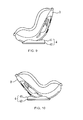
- FIG. 7 is a schematic view illustrating the seat 3 locked in a first position substantially erecting upward from the base 4. In this first position, the latching portions 53 can engage with one pair of the first locking grooves 35a for securely locking the seat 3 in place.
- FIG. 9 is a schematic view illustrating the seat 3 locked in an intermediate second position slightly inclined backward from the first position shown in FIG. 7 .
- the latching portions 53 can engage with another pair of the first locking grooves 35a for securely locking the seat 3 in place.
- FIG. 10 is a schematic view illustrating the seat 3 locked in a reclined third position.
- the latching portions 53 can engage with the second locking grooves 35b for locking the seat 3.
- the reclined position may be particularly suitable when the child safety seat assembly 2 is used for seating a child in a car oriented backward, in compliance with current safety regulations.
- the stop abutment 34 located at the front of each flange 33 can respectively reach the corresponding enlarged opening 415 and abut against the front end abutment 416 for blocking excessive backward movement that may result in separation of the seat 3 from the base 4.
- the stop abutment 34 located at the rear of each flange 33 can respectively abut against the rear end abutment 416 for blocking excessive forward movement that may result in separation of the seat 3 from the base 4.
- At least one advantage of the seat assembly described herein is the ability to adjust the inclination of a seat on a base, and lock the position of the seat via a latch mechanism that is simple in construction. Because the latch mechanism can be fabricated with a reduced number of component parts, the manufacture cost of the child safety seat assembly can be reduced.
- FIG. 11 is a schematic view that illustrates such variant embodiment.
- the seat 3' can include a seating portion 31' provided with a raised portion 311' that protrudes from a bottom of the seating portion 31' and encloses a latch mechanism 5' between the two rail portions 32'.
- the latch mechanism 5' can be similar to the latch mechanism 5 in construction, comprising a flexible sliding element 51' and a spring 6' (drawn with dotted lines).
- the sliding element 51' can have two resilient arms 52' that are respectively joined with opposite lateral sides of the sliding element 51', and latching portions 53' formed at the distal ends of the resilient arms 52'.
- the resilient arms 52' can extend from the front toward the rear, and bend laterally away in opposite directions from a central region of the sliding element 51'.
- the sliding element 51', including the resilient arms 52' and latching portions 53' may be formed in a single body by molding.
- the latch mechanism 5' may also comprise a restraining structure (not shown for the sake of clarity) that is similar to the restraining structure 417 in construction for guiding movement of the sliding element 51' and latching portions 53' relative to the seat 3'.
- the base 4' may include a recessed cavity 410' that is located between the left and right recessed portions 411' at a position corresponding to the raised portion 311'.
- Two opposite sidewalls of the recessed cavity 410' may comprise a plurality of locking locations 45', which can include three first locking grooves 45a', and a remote second locking groove 45b'.
- the rail portions 32' and raised portion 311' are respectively lodged in the recessed portions 411' and recessed cavity 410'.
- the sliding element 51' of the latch mechanism 5' can be pulled toward the front of the seat 3' for laterally disengaging the latching portions 53' from any pairs of the locking locations 45'.
- the sliding element 51' can move toward the rear of the seat 3' under the biasing action of the spring 6', and the latching portions 53' can consequently engage with a new pairs of the locking locations 45' for locking the seat 3' with the base 4'. Because the latch mechanism 5' is placed toward the front of the seat 3', it can be easily accessible and operated by a user.
Applications Claiming Priority (2)
| Application Number | Priority Date | Filing Date | Title |
|---|---|---|---|
| CN200910161179.8A CN101986960B (zh) | 2009-08-03 | 2009-08-03 | 幼儿安全座椅组合体和其调整装置 |
| EP10171763.5A EP2281714B1 (de) | 2009-08-03 | 2010-08-03 | Einstellbare Kindersicherheitssitzanordnung |
Related Parent Applications (2)
| Application Number | Title | Priority Date | Filing Date |
|---|---|---|---|
| EP10171763.5A Division EP2281714B1 (de) | 2009-08-03 | 2010-08-03 | Einstellbare Kindersicherheitssitzanordnung |
| EP10171763.5A Division-Into EP2281714B1 (de) | 2009-08-03 | 2010-08-03 | Einstellbare Kindersicherheitssitzanordnung |
Publications (2)
| Publication Number | Publication Date |
|---|---|
| EP2894059A1 true EP2894059A1 (de) | 2015-07-15 |
| EP2894059B1 EP2894059B1 (de) | 2020-06-17 |
Family
ID=43042185
Family Applications (2)
| Application Number | Title | Priority Date | Filing Date |
|---|---|---|---|
| EP15150479.2A Active EP2894059B1 (de) | 2009-08-03 | 2010-08-03 | Einstellbare Kindersicherheitssitzanordnung |
| EP10171763.5A Active EP2281714B1 (de) | 2009-08-03 | 2010-08-03 | Einstellbare Kindersicherheitssitzanordnung |
Family Applications After (1)
| Application Number | Title | Priority Date | Filing Date |
|---|---|---|---|
| EP10171763.5A Active EP2281714B1 (de) | 2009-08-03 | 2010-08-03 | Einstellbare Kindersicherheitssitzanordnung |
Country Status (6)
| Country | Link |
|---|---|
| US (1) | US8585143B2 (de) |
| EP (2) | EP2894059B1 (de) |
| JP (1) | JP5425013B2 (de) |
| CN (1) | CN101986960B (de) |
| BR (1) | BRPI1003239B1 (de) |
| ES (2) | ES2804585T3 (de) |
Families Citing this family (20)
| Publication number | Priority date | Publication date | Assignee | Title |
|---|---|---|---|---|
| CN102336153B (zh) * | 2010-07-15 | 2014-12-24 | 明门香港股份有限公司 | 婴儿座椅 |
| CN102727001B (zh) * | 2011-03-31 | 2015-04-29 | 王鲲 | 高脚椅 |
| DE202012013706U1 (de) * | 2011-07-29 | 2019-11-20 | Wonderland Switzerland Ag | Kinder-Sicherheitssitzbaugruppe mit Ankersystemen |
| US9688299B2 (en) | 2012-05-01 | 2017-06-27 | Safe-Strap Company, Inc. | Infant carrier holder |
| US9540026B2 (en) | 2012-05-01 | 2017-01-10 | Safe-Strap Company, Inc. | Infant carrier holder |
| USD758085S1 (en) * | 2013-05-30 | 2016-06-07 | Smart Trike Mnf Pte Ltd. | Chair for tricycle |
| ES2700725T3 (es) * | 2013-10-23 | 2019-02-19 | Wonderland Switzerland Ag | Asiento de seguridad para niños |
| JP6374232B2 (ja) * | 2014-06-17 | 2018-08-15 | 株式会社シーエー産商 | チャイルドシート |
| KR101594154B1 (ko) * | 2014-10-21 | 2016-02-15 | 정종락 | 유아용 카시트 |
| KR101595115B1 (ko) * | 2014-12-11 | 2016-02-17 | 정종락 | 쿠션부가 구비된 유아용 카시트 |
| US9873359B2 (en) * | 2014-12-23 | 2018-01-23 | Wonderland Nurserygoods Company Limited | Child safety seat |
| US10351027B2 (en) * | 2015-01-29 | 2019-07-16 | Artsana Usa, Inc. | Carry handle release mechanism for a child seat |
| US10086722B2 (en) * | 2015-10-30 | 2018-10-02 | Dorel Juvenile Group, Inc. | Child restraint |
| CN106671836B (zh) * | 2015-11-06 | 2020-04-03 | 宝钜儿童用品香港股份有限公司 | 调整机构及具有该调整机构的儿童安全座椅 |
| US10427559B2 (en) | 2016-10-07 | 2019-10-01 | Dorel Juvenile Group, Inc. | Child restraint system with seat-orientation adjuster |
| CN108725275B (zh) * | 2018-05-29 | 2024-04-05 | 上海沃雨电子科技有限公司 | 儿童安全座椅及其isofix双向调节结构 |
| CN108839591B (zh) * | 2018-06-11 | 2023-11-24 | 好孩子儿童用品有限公司 | 一种儿童汽车安全座调平装置及儿童汽车安全座 |
| CA3047971C (en) * | 2018-07-05 | 2023-06-27 | Britax Child Safety, Inc. | Multi-functional energy absorber |
| CN109624800B (zh) * | 2018-12-18 | 2024-04-09 | 清华大学苏州汽车研究院(相城) | 一种用于儿童安全座椅的isofix调节装置 |
| TW202400431A (zh) * | 2022-06-13 | 2024-01-01 | 瑞士商明門瑞士股份有限公司 | 座椅角度調整機構、支撐板以及兒童安全座椅 |
Citations (3)
| Publication number | Priority date | Publication date | Assignee | Title |
|---|---|---|---|---|
| EP0228158A2 (de) * | 1985-10-30 | 1987-07-08 | Ase (Uk) Limited | Kindersicherheitssitz |
| EP0609889A1 (de) * | 1993-02-04 | 1994-08-10 | OSANN DESIGN ENTWICKLUNGS- UND PRODUKTIONS-GmbH, KINDERSICHERHEITSSYTEME | Kindersicherheitssitz für Fahrzeuge |
| US5890762A (en) | 1996-10-17 | 1999-04-06 | Takata Corporation | Child seat |
Family Cites Families (11)
| Publication number | Priority date | Publication date | Assignee | Title |
|---|---|---|---|---|
| FR2449549A1 (fr) * | 1979-02-21 | 1980-09-19 | Cousin Cie Ets A & M Freres | Glissieres pour siege de vehicule comportant un organe-memoire de positionnement |
| JPS63235137A (ja) * | 1987-03-25 | 1988-09-30 | Takata Kk | 幼児用拘束保護シ−ト |
| GB8804469D0 (en) * | 1988-02-25 | 1988-03-23 | Roemer Britax Autogurte Gmbh | Childs safety seat |
| JP3295183B2 (ja) | 1993-06-30 | 2002-06-24 | アップリカ▲葛▼西株式会社 | 自動車用子供安全シート |
| US5551751A (en) * | 1994-07-12 | 1996-09-03 | Century Products Company | Reclining restraint (smart move) |
| AUPN649595A0 (en) * | 1995-11-10 | 1995-12-07 | Britax Child-Care Products Pty Ltd | Reclining mechanism and latch for child safety seat |
| CN2846210Y (zh) * | 2005-07-02 | 2006-12-13 | 重庆长安汽车股份有限公司 | 具有双向调节功能的汽车座椅滑动导轨 |
| JP2007055433A (ja) * | 2005-08-24 | 2007-03-08 | Takata Corp | チャイルドシート |
| CN201076241Y (zh) * | 2007-08-14 | 2008-06-25 | 明门实业股份有限公司 | 单手高度调整机构及具有该调整机构的座椅 |
| EP2036766A1 (de) * | 2007-09-13 | 2009-03-18 | Team-Tex | Kindersitz |
| CN201192994Y (zh) * | 2008-04-10 | 2009-02-11 | 宁波新宝工业有限公司 | 汽车座椅的调节定位装置 |
-
2009
- 2009-08-03 CN CN200910161179.8A patent/CN101986960B/zh active Active
-
2010
- 2010-07-28 JP JP2010169377A patent/JP5425013B2/ja active Active
- 2010-08-02 US US12/848,341 patent/US8585143B2/en active Active
- 2010-08-03 BR BRPI1003239-8A patent/BRPI1003239B1/pt active IP Right Grant
- 2010-08-03 ES ES15150479T patent/ES2804585T3/es active Active
- 2010-08-03 ES ES10171763.5T patent/ES2534048T3/es active Active
- 2010-08-03 EP EP15150479.2A patent/EP2894059B1/de active Active
- 2010-08-03 EP EP10171763.5A patent/EP2281714B1/de active Active
Patent Citations (3)
| Publication number | Priority date | Publication date | Assignee | Title |
|---|---|---|---|---|
| EP0228158A2 (de) * | 1985-10-30 | 1987-07-08 | Ase (Uk) Limited | Kindersicherheitssitz |
| EP0609889A1 (de) * | 1993-02-04 | 1994-08-10 | OSANN DESIGN ENTWICKLUNGS- UND PRODUKTIONS-GmbH, KINDERSICHERHEITSSYTEME | Kindersicherheitssitz für Fahrzeuge |
| US5890762A (en) | 1996-10-17 | 1999-04-06 | Takata Corporation | Child seat |
Also Published As
| Publication number | Publication date |
|---|---|
| JP5425013B2 (ja) | 2014-02-26 |
| US8585143B2 (en) | 2013-11-19 |
| BRPI1003239B1 (pt) | 2019-11-12 |
| JP2011031880A (ja) | 2011-02-17 |
| EP2281714A1 (de) | 2011-02-09 |
| CN101986960A (zh) | 2011-03-23 |
| CN101986960B (zh) | 2014-07-16 |
| EP2281714B1 (de) | 2015-02-25 |
| BRPI1003239A2 (pt) | 2012-04-10 |
| ES2534048T3 (es) | 2015-04-16 |
| ES2804585T3 (es) | 2021-02-08 |
| EP2894059B1 (de) | 2020-06-17 |
| US20110025110A1 (en) | 2011-02-03 |
Similar Documents
| Publication | Publication Date | Title |
|---|---|---|
| EP2894059B1 (de) | Einstellbare Kindersicherheitssitzanordnung | |
| US8870285B2 (en) | Child safety seat assembly | |
| EP3165400B1 (de) | Kindersicherheitssitz | |
| US6742846B1 (en) | Modified head restraint assembly for motor vehicle seats | |
| KR102225761B1 (ko) | 개선된 레일 설계를 가진 차량 시트용 슬라이딩 장치 | |
| US8899678B2 (en) | Reclinable child seat assembly | |
| US11667219B2 (en) | Child safety seat | |
| CA2763903A1 (en) | Child safety seat assembly | |
| GB2492270A (en) | Child safety seat assembly | |
| EP2450226B1 (de) | Kindersitz | |
| EP1477358B1 (de) | Ein Kindersitz mit Armlehnen für Kraftfahrzeuge | |
| CN107539264A (zh) | 安装在座椅上的可调节安全带的织带引导件 | |
| CN112406646A (zh) | 儿童安全座椅 | |
| EP0936103A2 (de) | Sitzgleitvorrichtung | |
| TWI377139B (en) | Assembly of child safety seat and adjusting device thereof | |
| CN215794183U (zh) | 一种车座组件 | |
| TWM397331U (en) | Child safety seat and adjusting device therefor | |
| CN114379433A (zh) | 用于安全座椅的支撑脚装置的指示组件和安全座椅 |
Legal Events
| Date | Code | Title | Description |
|---|---|---|---|
| PUAI | Public reference made under article 153(3) epc to a published international application that has entered the european phase |
Free format text: ORIGINAL CODE: 0009012 |
|
| 17P | Request for examination filed |
Effective date: 20150108 |
|
| AC | Divisional application: reference to earlier application |
Ref document number: 2281714 Country of ref document: EP Kind code of ref document: P |
|
| AK | Designated contracting states |
Kind code of ref document: A1 Designated state(s): AL AT BE BG CH CY CZ DE DK EE ES FI FR GB GR HR HU IE IS IT LI LT LU LV MC MK MT NL NO PL PT RO SE SI SK SM TR |
|
| RBV | Designated contracting states (corrected) |
Designated state(s): AL AT BE BG CH CY CZ DE DK EE ES FI FR GB GR HR HU IE IS IT LI LT LU LV MC MK MT NL NO PL PT RO SE SI SK SM TR |
|
| RAP1 | Party data changed (applicant data changed or rights of an application transferred) |
Owner name: WONDERLAND NURSERYGOODS COMPANY LIMITED |
|
| RAP1 | Party data changed (applicant data changed or rights of an application transferred) |
Owner name: WONDERLAND SWITZERLAND AG |
|
| STAA | Information on the status of an ep patent application or granted ep patent |
Free format text: STATUS: EXAMINATION IS IN PROGRESS |
|
| 17Q | First examination report despatched |
Effective date: 20181029 |
|
| GRAP | Despatch of communication of intention to grant a patent |
Free format text: ORIGINAL CODE: EPIDOSNIGR1 |
|
| STAA | Information on the status of an ep patent application or granted ep patent |
Free format text: STATUS: GRANT OF PATENT IS INTENDED |
|
| INTG | Intention to grant announced |
Effective date: 20200109 |
|
| GRAS | Grant fee paid |
Free format text: ORIGINAL CODE: EPIDOSNIGR3 |
|
| GRAA | (expected) grant |
Free format text: ORIGINAL CODE: 0009210 |
|
| STAA | Information on the status of an ep patent application or granted ep patent |
Free format text: STATUS: THE PATENT HAS BEEN GRANTED |
|
| AC | Divisional application: reference to earlier application |
Ref document number: 2281714 Country of ref document: EP Kind code of ref document: P |
|
| AK | Designated contracting states |
Kind code of ref document: B1 Designated state(s): AL AT BE BG CH CY CZ DE DK EE ES FI FR GB GR HR HU IE IS IT LI LT LU LV MC MK MT NL NO PL PT RO SE SI SK SM TR |
|
| REG | Reference to a national code |
Ref country code: GB Ref legal event code: FG4D |
|
| REG | Reference to a national code |
Ref country code: CH Ref legal event code: EP |
|
| REG | Reference to a national code |
Ref country code: IE Ref legal event code: FG4D |
|
| REG | Reference to a national code |
Ref country code: DE Ref legal event code: R096 Ref document number: 602010064690 Country of ref document: DE |
|
| REG | Reference to a national code |
Ref country code: AT Ref legal event code: REF Ref document number: 1280910 Country of ref document: AT Kind code of ref document: T Effective date: 20200715 |
|
| REG | Reference to a national code |
Ref country code: NL Ref legal event code: FP |
|
| REG | Reference to a national code |
Ref country code: SE Ref legal event code: TRGR |
|
| PG25 | Lapsed in a contracting state [announced via postgrant information from national office to epo] |
Ref country code: FI Free format text: LAPSE BECAUSE OF FAILURE TO SUBMIT A TRANSLATION OF THE DESCRIPTION OR TO PAY THE FEE WITHIN THE PRESCRIBED TIME-LIMIT Effective date: 20200617 Ref country code: NO Free format text: LAPSE BECAUSE OF FAILURE TO SUBMIT A TRANSLATION OF THE DESCRIPTION OR TO PAY THE FEE WITHIN THE PRESCRIBED TIME-LIMIT Effective date: 20200917 Ref country code: LT Free format text: LAPSE BECAUSE OF FAILURE TO SUBMIT A TRANSLATION OF THE DESCRIPTION OR TO PAY THE FEE WITHIN THE PRESCRIBED TIME-LIMIT Effective date: 20200617 Ref country code: GR Free format text: LAPSE BECAUSE OF FAILURE TO SUBMIT A TRANSLATION OF THE DESCRIPTION OR TO PAY THE FEE WITHIN THE PRESCRIBED TIME-LIMIT Effective date: 20200918 |
|
| REG | Reference to a national code |
Ref country code: LT Ref legal event code: MG4D |
|
| PG25 | Lapsed in a contracting state [announced via postgrant information from national office to epo] |
Ref country code: BG Free format text: LAPSE BECAUSE OF FAILURE TO SUBMIT A TRANSLATION OF THE DESCRIPTION OR TO PAY THE FEE WITHIN THE PRESCRIBED TIME-LIMIT Effective date: 20200917 Ref country code: HR Free format text: LAPSE BECAUSE OF FAILURE TO SUBMIT A TRANSLATION OF THE DESCRIPTION OR TO PAY THE FEE WITHIN THE PRESCRIBED TIME-LIMIT Effective date: 20200617 Ref country code: LV Free format text: LAPSE BECAUSE OF FAILURE TO SUBMIT A TRANSLATION OF THE DESCRIPTION OR TO PAY THE FEE WITHIN THE PRESCRIBED TIME-LIMIT Effective date: 20200617 |
|
| REG | Reference to a national code |
Ref country code: AT Ref legal event code: MK05 Ref document number: 1280910 Country of ref document: AT Kind code of ref document: T Effective date: 20200617 |
|
| PG25 | Lapsed in a contracting state [announced via postgrant information from national office to epo] |
Ref country code: AL Free format text: LAPSE BECAUSE OF FAILURE TO SUBMIT A TRANSLATION OF THE DESCRIPTION OR TO PAY THE FEE WITHIN THE PRESCRIBED TIME-LIMIT Effective date: 20200617 |
|
| PG25 | Lapsed in a contracting state [announced via postgrant information from national office to epo] |
Ref country code: SM Free format text: LAPSE BECAUSE OF FAILURE TO SUBMIT A TRANSLATION OF THE DESCRIPTION OR TO PAY THE FEE WITHIN THE PRESCRIBED TIME-LIMIT Effective date: 20200617 Ref country code: EE Free format text: LAPSE BECAUSE OF FAILURE TO SUBMIT A TRANSLATION OF THE DESCRIPTION OR TO PAY THE FEE WITHIN THE PRESCRIBED TIME-LIMIT Effective date: 20200617 Ref country code: AT Free format text: LAPSE BECAUSE OF FAILURE TO SUBMIT A TRANSLATION OF THE DESCRIPTION OR TO PAY THE FEE WITHIN THE PRESCRIBED TIME-LIMIT Effective date: 20200617 Ref country code: PT Free format text: LAPSE BECAUSE OF FAILURE TO SUBMIT A TRANSLATION OF THE DESCRIPTION OR TO PAY THE FEE WITHIN THE PRESCRIBED TIME-LIMIT Effective date: 20201019 Ref country code: CZ Free format text: LAPSE BECAUSE OF FAILURE TO SUBMIT A TRANSLATION OF THE DESCRIPTION OR TO PAY THE FEE WITHIN THE PRESCRIBED TIME-LIMIT Effective date: 20200617 Ref country code: RO Free format text: LAPSE BECAUSE OF FAILURE TO SUBMIT A TRANSLATION OF THE DESCRIPTION OR TO PAY THE FEE WITHIN THE PRESCRIBED TIME-LIMIT Effective date: 20200617 |
|
| REG | Reference to a national code |
Ref country code: ES Ref legal event code: FG2A Ref document number: 2804585 Country of ref document: ES Kind code of ref document: T3 Effective date: 20210208 |
|
| PG25 | Lapsed in a contracting state [announced via postgrant information from national office to epo] |
Ref country code: IS Free format text: LAPSE BECAUSE OF FAILURE TO SUBMIT A TRANSLATION OF THE DESCRIPTION OR TO PAY THE FEE WITHIN THE PRESCRIBED TIME-LIMIT Effective date: 20201017 Ref country code: PL Free format text: LAPSE BECAUSE OF FAILURE TO SUBMIT A TRANSLATION OF THE DESCRIPTION OR TO PAY THE FEE WITHIN THE PRESCRIBED TIME-LIMIT Effective date: 20200617 Ref country code: SK Free format text: LAPSE BECAUSE OF FAILURE TO SUBMIT A TRANSLATION OF THE DESCRIPTION OR TO PAY THE FEE WITHIN THE PRESCRIBED TIME-LIMIT Effective date: 20200617 |
|
| REG | Reference to a national code |
Ref country code: DE Ref legal event code: R097 Ref document number: 602010064690 Country of ref document: DE |
|
| PG25 | Lapsed in a contracting state [announced via postgrant information from national office to epo] |
Ref country code: MC Free format text: LAPSE BECAUSE OF FAILURE TO SUBMIT A TRANSLATION OF THE DESCRIPTION OR TO PAY THE FEE WITHIN THE PRESCRIBED TIME-LIMIT Effective date: 20200617 |
|
| REG | Reference to a national code |
Ref country code: CH Ref legal event code: PL |
|
| PLBE | No opposition filed within time limit |
Free format text: ORIGINAL CODE: 0009261 |
|
| STAA | Information on the status of an ep patent application or granted ep patent |
Free format text: STATUS: NO OPPOSITION FILED WITHIN TIME LIMIT |
|
| PG25 | Lapsed in a contracting state [announced via postgrant information from national office to epo] |
Ref country code: LI Free format text: LAPSE BECAUSE OF NON-PAYMENT OF DUE FEES Effective date: 20200831 Ref country code: LU Free format text: LAPSE BECAUSE OF NON-PAYMENT OF DUE FEES Effective date: 20200803 Ref country code: CH Free format text: LAPSE BECAUSE OF NON-PAYMENT OF DUE FEES Effective date: 20200831 Ref country code: DK Free format text: LAPSE BECAUSE OF FAILURE TO SUBMIT A TRANSLATION OF THE DESCRIPTION OR TO PAY THE FEE WITHIN THE PRESCRIBED TIME-LIMIT Effective date: 20200617 |
|
| 26N | No opposition filed |
Effective date: 20210318 |
|
| REG | Reference to a national code |
Ref country code: BE Ref legal event code: MM Effective date: 20200831 |
|
| PG25 | Lapsed in a contracting state [announced via postgrant information from national office to epo] |
Ref country code: SI Free format text: LAPSE BECAUSE OF FAILURE TO SUBMIT A TRANSLATION OF THE DESCRIPTION OR TO PAY THE FEE WITHIN THE PRESCRIBED TIME-LIMIT Effective date: 20200617 |
|
| PG25 | Lapsed in a contracting state [announced via postgrant information from national office to epo] |
Ref country code: IE Free format text: LAPSE BECAUSE OF NON-PAYMENT OF DUE FEES Effective date: 20200803 Ref country code: BE Free format text: LAPSE BECAUSE OF NON-PAYMENT OF DUE FEES Effective date: 20200831 |
|
| PG25 | Lapsed in a contracting state [announced via postgrant information from national office to epo] |
Ref country code: TR Free format text: LAPSE BECAUSE OF FAILURE TO SUBMIT A TRANSLATION OF THE DESCRIPTION OR TO PAY THE FEE WITHIN THE PRESCRIBED TIME-LIMIT Effective date: 20200617 Ref country code: MT Free format text: LAPSE BECAUSE OF FAILURE TO SUBMIT A TRANSLATION OF THE DESCRIPTION OR TO PAY THE FEE WITHIN THE PRESCRIBED TIME-LIMIT Effective date: 20200617 Ref country code: CY Free format text: LAPSE BECAUSE OF FAILURE TO SUBMIT A TRANSLATION OF THE DESCRIPTION OR TO PAY THE FEE WITHIN THE PRESCRIBED TIME-LIMIT Effective date: 20200617 |
|
| PG25 | Lapsed in a contracting state [announced via postgrant information from national office to epo] |
Ref country code: MK Free format text: LAPSE BECAUSE OF FAILURE TO SUBMIT A TRANSLATION OF THE DESCRIPTION OR TO PAY THE FEE WITHIN THE PRESCRIBED TIME-LIMIT Effective date: 20200617 |
|
| P01 | Opt-out of the competence of the unified patent court (upc) registered |
Effective date: 20230522 |
|
| PGFP | Annual fee paid to national office [announced via postgrant information from national office to epo] |
Ref country code: SE Payment date: 20230630 Year of fee payment: 14 |
|
| PGFP | Annual fee paid to national office [announced via postgrant information from national office to epo] |
Ref country code: NL Payment date: 20230825 Year of fee payment: 14 |
|
| PGFP | Annual fee paid to national office [announced via postgrant information from national office to epo] |
Ref country code: IT Payment date: 20230822 Year of fee payment: 14 Ref country code: GB Payment date: 20230711 Year of fee payment: 14 Ref country code: ES Payment date: 20230914 Year of fee payment: 14 |
|
| PGFP | Annual fee paid to national office [announced via postgrant information from national office to epo] |
Ref country code: FR Payment date: 20230711 Year of fee payment: 14 Ref country code: DE Payment date: 20230707 Year of fee payment: 14 |