EP2893403B1 - Flexibler anker mit konstanter kraft - Google Patents
Flexibler anker mit konstanter kraft Download PDFInfo
- Publication number
- EP2893403B1 EP2893403B1 EP13756165.0A EP13756165A EP2893403B1 EP 2893403 B1 EP2893403 B1 EP 2893403B1 EP 13756165 A EP13756165 A EP 13756165A EP 2893403 B1 EP2893403 B1 EP 2893403B1
- Authority
- EP
- European Patent Office
- Prior art keywords
- fork
- head
- flexible
- pivot
- energy
- Prior art date
- Legal status (The legal status is an assumption and is not a legal conclusion. Google has not performed a legal analysis and makes no representation as to the accuracy of the status listed.)
- Active
Links
- 230000009975 flexible effect Effects 0.000 title claims description 98
- 230000007246 mechanism Effects 0.000 claims description 52
- 230000033001 locomotion Effects 0.000 claims description 22
- 238000013519 translation Methods 0.000 claims description 11
- 230000009471 action Effects 0.000 claims description 6
- 229910052814 silicon oxide Inorganic materials 0.000 claims description 4
- 229910052710 silicon Inorganic materials 0.000 claims description 3
- 239000010703 silicon Substances 0.000 claims description 3
- VYPSYNLAJGMNEJ-UHFFFAOYSA-N Silicium dioxide Chemical compound O=[Si]=O VYPSYNLAJGMNEJ-UHFFFAOYSA-N 0.000 claims description 2
- OFNHPGDEEMZPFG-UHFFFAOYSA-N phosphanylidynenickel Chemical compound [P].[Ni] OFNHPGDEEMZPFG-UHFFFAOYSA-N 0.000 claims description 2
- 239000010437 gem Substances 0.000 claims 9
- 229910001751 gemstone Inorganic materials 0.000 claims 9
- 239000005300 metallic glass Substances 0.000 claims 1
- 230000000284 resting effect Effects 0.000 description 14
- 239000004575 stone Substances 0.000 description 12
- BASFCYQUMIYNBI-UHFFFAOYSA-N platinum Chemical compound [Pt] BASFCYQUMIYNBI-UHFFFAOYSA-N 0.000 description 9
- 238000006073 displacement reaction Methods 0.000 description 7
- 229940082150 encore Drugs 0.000 description 6
- 238000010586 diagram Methods 0.000 description 5
- 230000008901 benefit Effects 0.000 description 4
- 230000010355 oscillation Effects 0.000 description 4
- XUIMIQQOPSSXEZ-UHFFFAOYSA-N Silicon Chemical compound [Si] XUIMIQQOPSSXEZ-UHFFFAOYSA-N 0.000 description 3
- 230000000703 anti-shock Effects 0.000 description 3
- 230000000694 effects Effects 0.000 description 3
- 230000003993 interaction Effects 0.000 description 3
- 238000004519 manufacturing process Methods 0.000 description 3
- 210000003423 ankle Anatomy 0.000 description 2
- 238000000034 method Methods 0.000 description 2
- 230000036316 preload Effects 0.000 description 2
- 230000035939 shock Effects 0.000 description 2
- LIVNPJMFVYWSIS-UHFFFAOYSA-N silicon monoxide Chemical class [Si-]#[O+] LIVNPJMFVYWSIS-UHFFFAOYSA-N 0.000 description 2
- 238000012546 transfer Methods 0.000 description 2
- 230000001052 transient effect Effects 0.000 description 2
- 241000287107 Passer Species 0.000 description 1
- 238000013459 approach Methods 0.000 description 1
- 230000005540 biological transmission Effects 0.000 description 1
- 230000000903 blocking effect Effects 0.000 description 1
- 230000000295 complement effect Effects 0.000 description 1
- 230000001143 conditioned effect Effects 0.000 description 1
- 235000021186 dishes Nutrition 0.000 description 1
- 235000021183 entrée Nutrition 0.000 description 1
- 239000011521 glass Substances 0.000 description 1
- 238000010348 incorporation Methods 0.000 description 1
- 230000001939 inductive effect Effects 0.000 description 1
- 230000001788 irregular Effects 0.000 description 1
- 238000012423 maintenance Methods 0.000 description 1
- 239000000463 material Substances 0.000 description 1
- 239000002184 metal Substances 0.000 description 1
- 229910052751 metal Inorganic materials 0.000 description 1
- 238000009417 prefabrication Methods 0.000 description 1
- 230000008569 process Effects 0.000 description 1
Images


Classifications
-
- G—PHYSICS
- G04—HOROLOGY
- G04B—MECHANICALLY-DRIVEN CLOCKS OR WATCHES; MECHANICAL PARTS OF CLOCKS OR WATCHES IN GENERAL; TIME PIECES USING THE POSITION OF THE SUN, MOON OR STARS
- G04B15/00—Escapements
- G04B15/06—Free escapements
- G04B15/08—Lever escapements
-
- G—PHYSICS
- G04—HOROLOGY
- G04B—MECHANICALLY-DRIVEN CLOCKS OR WATCHES; MECHANICAL PARTS OF CLOCKS OR WATCHES IN GENERAL; TIME PIECES USING THE POSITION OF THE SUN, MOON OR STARS
- G04B15/00—Escapements
- G04B15/10—Escapements with constant impulses for the regulating mechanism
-
- G—PHYSICS
- G04—HOROLOGY
- G04B—MECHANICALLY-DRIVEN CLOCKS OR WATCHES; MECHANICAL PARTS OF CLOCKS OR WATCHES IN GENERAL; TIME PIECES USING THE POSITION OF THE SUN, MOON OR STARS
- G04B15/00—Escapements
- G04B15/14—Component parts or constructional details, e.g. construction of the lever or the escape wheel
Definitions
- the invention relates to a clock escapement mechanism, comprising at least one platen carrying an escape wheel and a rocker cooperating with the same anchor comprising an anchor head carrying at least one pallet. and / or an output pallet and arranged to cooperate with an escape wheel, said anchor further comprising a fork arranged to cooperate with a pendulum.
- the invention also relates to a watch movement comprising at least one such escape mechanism.
- the invention also relates to a timepiece comprising at least one such watch movement, and / or at least one such escape mechanism.
- the invention relates to the field of watch exhaust mechanisms.
- the regularity of the operation of an escape mechanism is conditioned by a good control of the maintenance of the oscillations and in particular the impulse, whose intensity can be irregular in a watch whose torque varies.
- the document FR 2 928 015 A1 in the name of LENOBLE describes a tangential pulse anchor escapement device for a watch, comprising a toothed escape wheel, an anchor and at least one balance spring.
- the anchor is in two parts each pivoting on a separate axis, the two parts are hinged together by two transmission arms terminating at their adjacent ends by a common joint to rotate the two parts of the anchor at the same speed but in opposite directions.
- Each part of the anchor comprises a rest lift and a pulse lift, the latter receiving thrusts of the teeth of the escape wheel in a tangential manner.
- This escapement device comprises two spiral rockers with distinct oscillating axes of rotation, and each part of the anchor comprises a fork that can engage drive on an ellipse of the corresponding balance spring.
- WO2011 / 064682 A1 in the name of FERRARA relates to an anchor in two parts hinged together, the articulation comprising a cam eccentric integral with the part of the carrier anchor horns and dart, and cooperating with a fork secured to the pallet carrier portion of the carrier.
- the document EP 2,105,806 in the name of GIRARD PERREGAUX discloses an escapement mechanism arranged to transmit pulses from a power source to an oscillating regulator such as a sprung balance, via a leaf spring which buckles around a point of inflection .
- This leaf spring is capable of accumulating the energy of the driving source between two pulses, and of transmitting it to the oscillating regulator at each pulse by means of a first and a second latch.
- the leaf spring is mounted on a frame which is deformable symmetrically with respect to a first axis passing through the axes of rotation of the regulator, the first and second latches, and by the point d inflection, as well as with respect to a second axis perpendicular to the first axis and passing through the ends of the leaf spring.
- the invention proposes, on the one hand, to regulate the intensity of the pulse applied to the balance, and on the other hand to reduce the inertia in motion during the oscillation.
- the invention relates to a clock escapement mechanism according to claim 1.
- the invention also relates to a watch movement comprising at least one such escape mechanism.
- the invention also relates to a timepiece comprising at least one such watch movement, and / or at least one such escape mechanism.
- the invention relates to the field of watch exhaust mechanisms.
- the invention focuses on good control of the pulse.
- a constant force mechanism ensures repeatability over time.
- this bistable element is constituted by an anchor of particular constitution.
- the figure 21 shows the principle of a constant force mechanism, with a transfer of energy from a barrel 80, through a gear train 81, an escape wheel 20, an anchor 1, to a rocker 30.
- This mechanism comprises a flexible anchor figure 21 .
- the figure 22 illustrates the configuration of a bistable anchor. The invention proposes to combine these two architectures mechanisms to achieve maximum regularity, with high security, and a number reduced components, as well as a recessless recess.
- the invention comprises a watch exhaust anchor 1, comprising an anchor head 2, carrier of at least one entry pallet 3 and / or an exit pallet 4, and arranged to cooperate with an escape wheel 20.
- the anchor 1 further comprises a fork 6 arranged to cooperate with a rocker 30. The angular position of the fork 6 relative to the head 2 is variable.
- An object of the invention is to minimize the movements of the mechanical components.
- the release of energy from the anchor to the pendulum is studied to be in the form of an impulse.
- the anchor comprises means for storing and releasing energy, according to the respective positions of its moving components, here the head 2 and the fork 6. Note that intermediate stages could be added between the head and the fork, without departing from the invention.
- the preferred embodiment with a head and a fork has the advantage of minimizing the number of components, especially as it is possible to make a monobloc embodiment.
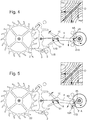
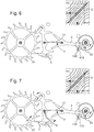
- each anchor comprises a spring, respectively straight 112 or S 113, prestressed between the head 2 and the fork 6.
- This spring 112 or 113 pushes the two halves of the anchor, and is free to rotate around its ends
- the figure 32 comprises in broken line the lever arm of the force, which is exerted in the direction of the spring 112, acting on the fork 6.
- the repulsion is not mechanical in nature, but by nature magnetic and / or electrostatic between a head and a fork 6 preferably pivotally mounted about two pivot axes 5 and 9.
- the head 2 and the fork 6 preferably follow motion axes, which are illustrated here with a particular embodiment where they are pivot axes. Indeed, the movements of the head 2 and the fork 6 are independent, and can in theory follow any kinematics, as long as compatible with the energy transfer between the escape wheel and the pendulum.
- the anchor 1 has a bistable behavior, and comprises at least one bistable element, preferably at least one flexible blade 10.
- a flexible blade is a simple embodiment, we can give other shapes to the bistable element without departing from the invention.
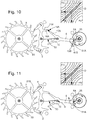
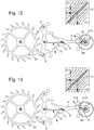
- the invention relates to a clockwork exhaust mechanism 100 comprising at least one plate 40 carrying an escape wheel 20 and a rocker 30 cooperating with the same anchor 1.
- the figure 41 illustrates a particular configuration where the two ends 101, 102, of the flexible blade 10 each pivot at a housing 1010, 1020, here v-shaped, carried respectively by the head 2 and the fork 6.
- the head 2 comprises a pin 71 which is supported on a spring arm 401, fixed to the plate 4 by fasteners 411, this spring tends to push the head 2 towards the fork 6; in the same way, the fork 6 comprises a pin 72 which is supported on a spring arm 402, fixed to the plate 4 by fasteners 412, this spring tends to push the fork 6 towards the head 6.
- At least one of the two housings 1010, 1020, and both in the particular example of the figure 41 is directly or indirectly (in this case via head 2 or fork 6 in the case of figure 41 ) to a return force putting the flexible blade 10 under prestressing buckling.
- the only direct permanent mechanical connection between the head 2 and the fork 6 is here ensured by at least one flexible blade 10, that is to say by a single flexible blade 10, or by a plurality of such flexible blades 10 mounted with similar way in prestressing buckling.
- the flexible blade 10 operates in buckling.
- the prestress is adjustable in the case of the application of a force or a couple.
- the blade 10 has in the free state a different geometry of the shapes it can take when the anchor 1 is incorporated in a mechanism of exhaust 100 and fixed on a plate 40.
- the anchor 1 comprises, for its attachment to a plate 40, first fastening means and / or guide carried by the head 2, and second fastening means and / or guide carried by the fork 6.
- Each of the two main components, head 2 and fork 6, may have mechanical links of conventional type, such as guidance in pivoting or translation, or have one or more fixed anchor points relative to the plate 40 and include flexible parts which give it a mobility relative to this plate, in pivoting and / or in translation, as described in the application PCT / EP2011 / 061244 or in the application EP 2 455 821 same depositor, in a configuration that will be described later in this "virtual pivot".
- the anchor head 2 is movable with respect to a first pivot axis 5 or pivots about this first axis 5, and the fork 6 is movable with respect to a second pivot axis 9 or pivots about this second axis 9 .
- the second axis 9 is distinct from the first axis 5.
- Figures 1 to 20 The particular achievement of Figures 1 to 20 is not limiting, and relates to a particular case where the head 2 is pivotally mounted about a first pivot axis 5.
- the fork 6 is pivotally mounted about a second pivot axis 9 of the first axis 5.
- these axes 5 and 9 are preferably distinct.
- the anchor 1 then comprises two bistable blades 10S and 10J, each having a first end 10ES, 10EJ, fixed to a plate not shown, and a second end 103S 103J recessed in respectively the fork 6 and the head 2.
- the head 2 and the fork 6 are partially superimposed and pivot about the same geometric axis of pivoting P, are connected by a return spring 104 in the form of a loop, hooked 104S in the range 6 and 104J in the head 2.
- This spring 104 which acts as a buffer spring, has a torque greater than that of the bistable.
- the figure 37 illustrates another form of anchor with two flexible coplanar bistable blades with the head 2 and the fork 6.
- Still other variants are feasible, for example with a substantially linear oscillating movement of the head 2 relative to the center line between the escape wheel 20 and the rocker 30, and a pivoting movement of the fork 6 around an axis 9.
- the fork 6 carries a stinger 7 with an anti-shock function to cooperate with a notch 34 of a plate 31 of the rocker 30, and at least one horn 8, here two horns 8, to cooperate with an ankle 35 of this balance 30 for the pulse function.
- the anchor 1 is articulated, that is to say that the head 2 and the fork 6 are movable relative to each other and indirectly connected to one another by at least one intermediate component, here a flexible blade 10, ensuring their relative mobility of movement.
- This bistable element is preferably in the form of a recessed beam.
- this beam is embedded at its two ends; the distance between the two ends is less than the length of beam at rest, which allows to have two stable positions, and at least one metastable position.
- the calculation of the energy stored in the bistable element can be made according to the angles taken by the bistable blade 10 at its two ends; or, in the case of several bistable blades, angles that each of them has, at each of its ends, with one of the components of the anchor 1, head 2 or fork 6, or plate 40, or other intermediate component according to the case.
- the combination of several slides can make it possible to obtain more stable states, for example three stable states by combining two blades.
- This at least one bistable element or flexible bistable blade 10 is mounted prestressed in buckling between the head 2 and the fork 6. And preferably the only direct mechanical link directly between the head 2 and the fork 6, that is to say except for their pivots or their fastenings to a plate 40 or similar, is provided by this at least one bistable blade 10.
- the flexible blade 10 has a first end 11 secured angularly to the head 2 and disposed in close proximity to the first axis 5, and a second end 12 angularly secured to the fork 6 and disposed in close proximity to the second axis 9 .
- first axis 5 and the second axis 9 are here geometric axes around which the pivoting of the head 2 and the fork 6 is performed. These axes do not necessarily correspond to conventional physical pivots, they can also be correspond to flexible pivots or virtual pivots.
- this anchor 1 carries an entry pallet 3 and an exit pallet 4.
- the entry pallet 3 or / and the output pallet 4 has a projecting end 13, in the form of a tongue visible on the figure 34 , opposite the first axis 5 and having a flat surface 14 adapted to receive a point 22 of a tooth 21 of an escape wheel 20, as visible on the figure 34 .
- the watch exhaust anchor 1 comprises an anchor head 2 carrying at least one entry pallet 3 and / or an exit pallet 4 and arranged to cooperate with a wheel of 20, and further comprises a fork 6 arranged to cooperate with a rocker 30.
- the angular position of the fork 6 relative to the head 2 is variable, and the only direct mechanical link directly between the head 2 and the fork 6 is provided by at least one flexible blade.
- the angular displacement in pivoting of the head 2 and that of the fork 6 are limited relative to each other by stops, and the head 2 comprises at least a first arm 15 having a first surface support and abutment 16 arranged to cooperate, in abutment or abutment, in certain relative positions of the head 2 and the fork 6, with a second abutment and abutment surface 18 that comprises at least one second arm 17 that includes the fork 6.
- arm 15 or 17 is not to be taken in a limiting sense, even if in the embodiment illustrated by the figures this component adopts an elongate shape, this arm 15 or 17 can take any form compatible with the kinematics of anchor.
- the deflection, in particular the angular deflection pivoting in the case of Figures 1 to 20 , head 2 and that of the fork 6 are thus limited relative to each other by stops.
- the head 2 comprises at least a first arm 15 having a first bearing and abutment surface 16 arranged to cooperate, abutting or resting, in certain relative positions of the head 2 and the fork 6, with a second bearing and abutment surface 18 that includes at least a second arm 17 that includes the fork 6.
- the head 2 comprises two first arms 15A, 15B, with first surfaces 16A, 16B, cooperating with second surfaces 18A, 18B, second arms 17A, 17B, of the fork 6.
- the anchor 1 is made integrally with this at least one flexible blade 10 or the bistable element: the head 2, the blade 10 and the fork 6 are a single component.
- the anchor 1 is advantageously made of silicon or silicon oxide or metal glass or nickel-phosphorus "LIGA” (especially obtained by a "LIGA” method).
- LIGA silicon or silicon oxide or metal glass or nickel-phosphorus
- the energy difference between corrugated positions (with a maximum stress level close to 400 MPa) and positions in simple arc, concave or convex, corresponds to a passage between energy passes at 0.5 ⁇ J and energy wells at 0.13 ⁇ J, a difference of 0.37 ⁇ J, which is comparable to the energy available at the wheel exhaust of caliber ETA 2824-2 at each alternation. This dimensioning is therefore sufficient to provide a pulse of normal intensity.
- the anchor 1 comprises a first flexible pivot 61 and / or a second flexible pivot 62 constituting a flexible guide at respectively the first axis 5 and / or the second axis 9.
- the anchor 1 comprises a first flexible pivot 61 or virtual and a second flexible pivot 62 or virtual two ends 101, 102 of the at least one flexible blade 10, each constituting a flexible guide at the level respectively of the first axis 5 and second axis 9.
- This first flexible pivot 61 or / and this second flexible pivot 62 may, again, be a virtual pivot.
- the figure 39 gives an example of head 2, connected to the plate 40 by two blades 2S and 2J, and whose first flexible pivot coincides with the pivot axis 23 of the escape wheel 20.
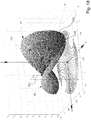
- the figure 18 shows an energy distribution diagram in the flexible blade 10 or the bistable element: in X and Y are represented the angles that make each of the two ends 101, 102, of the blade 10 with their points of attachment or of respective recesses 11, 12, on the anchor head 2 and on the fork 6.
- Z is represented a level of energy, graduated arbitrarily from 0 to 8.
- the figure 19 shows the projection on the XOY plane of this energy distribution layer, with the corresponding energy level curves.
- This energy distribution is saddle-shaped, symmetrical by relative to a vertical plane PS oriented along the bisector of the axes OX and OY.
- a dorsal D of very high energy level (6 to 8) extends in this plane of symmetry PS.
- the dorsal D is delimited by two energy passes first CE1 and second CE2, which each extend between two slopes of steep slope between the dorsal D and low energy zones, called energy wells, corresponding to stable positions.
- first PS1 and second PS2 (hollow of the energy layer).
- the energy passes CE1 and CE2 are each bordered by a high energy zone A1 and A2 respectively. These energy passes CE1 and CE2 correspond to two metastable positions.
- the figure 19 shows that the flexible blade 10 can not take any position of energy on the T web: the extreme parts of the anchor 1, in this case the head 2 and the fork 6, have a travel which is limited, either by second limiting pins 41A and 41B for the fork 6, or by limiting the pivoting of the head 2 by the second arms 17A, 17B, of the fork 6.
- the bistable blade 10 always pushes these end portions, head 2 and fork 6, anchor 1, against these stops.
- the limiting pins 41 are here represented on the plate. Note that they can take other positions, for example in the form of dishes under the teeth 21 of the escape wheel 20.
- the shape of the prestressed beam constituted by the bistable blade 10 is a non-limiting example.
- the concave, convex, S, Z geometries that the plate 10 can occupy are specific to the case in point. It is also possible to use a more complex geometry in the state of stable rest, for example in S or Z.
- the preferred choice to traverse a rectangle R, rather than a square, is explained by the objective of stopping before the energy pass, when the bistable blade 10 is rearmed.
- the risk would be that with a very small shock, the bistable blade 10 can tilt and, the sting 7 would then be blocked by the balance plate and rub against him permanently, this which is bad for walking and alters the yield.
- the stops are arranged so as to stop the bistable blade 10 before the first CE1 or the second CE2 energy col, during arming by energy charging of this bistable blade 10.
- Stops limiting the angular deflection of the head 2, respectively of the fork 6, are advantageously mobile and constituted by surfaces of the fork 6, respectively of the head 2.
- the angular displacement of the head 2 is limited by stops formed by two second arms 17A, 17B that includes the fork 6.
- the surfaces 18A, 18B form abutments equivalent to a non-drawing rest stop.
- they have an arcuate profile A centered on the second pivot axis 9, so that, when the pin 35 of the rocker 30 begins to drive the fork 6 (time T2 to time T3 below), the head 2 does not turn, there is only the friction to overcome.
- First limiting pins 48A, 48B are advantageously implanted near the head 2, as safeties in case of shocks or dynamic effects: for example, during the passage of time 6 to time 7, where the head 2 pivots in the second sense, for example, hourly: if it acquires too much speed, it may go too far, while in time 8 it must start in the other direction.
- the arming of the bistable blade 10 is done slowly, so that the inertia of the escape wheel. (or the rest of the gear) is high.
- the escape mechanism 100 comprises at least one plate 40 carrying an escape wheel 20 and at least one rocker 30 cooperating with the same anchor 1.
- the plate 40 has limiting pins 41 (41A, 41B in the figures) around the fork 6 in the vicinity of a plateau 31 of the balance 30.
- the second stone 44 or the second axis 45 is at a fixed distance, and in a fixed position in a particular embodiment, with respect to the first stone 42 or to the first axis 43.
- a second variant B the second stone 44 or the second axis 45 is movable, in particular guided in translation in a particular embodiment, in a variable position relative to the plate 40, and is subjected to the action of second elastic return means 47.
- first stone 42 or the first axis 43 is movable in this way.
- second stone 44 or the second axis 45 is movable otherwise than in translation, for example pivoting, or in any displacement.
- the plate 40 comprises, on the one hand a first stone 42 or a first axis 43 which is movable, in particular guided in translation in a particular embodiment, in a variable position relative to the plate 40 and is subject to the action of first elastic return means 46, for the pivotal guidance of the head 2, and secondly a second stone 44 or a second axis 45 which is movable, in particular guided in translation in a particular embodiment, in a position variable with respect to the plate 40 and is subjected to the action of second elastic return means 47, for the guidance in pivoting the range 6.
- the opposite configuration is feasible.
- the first stone 42 or the first axis 43 is movable otherwise than in translation, for example in pivoting, or in any displacement.
- the pivot axis 23 of the escape wheel 20, the pivot axis 32 of the rocker 30, the first stone 42 or respectively the first axis 43, the second stone 44 or respectively the second axis 45 are aligned.
- the figure 36 illustrates another configuration where the fork 6 is movable apart from the wheel-wheel alignment, and where the flexible blade 10 is deformed around an average position which is, for example and without limitation, a rope or an arc of a circle centered on the balance shaft; this configuration makes it possible to modify an existing movement comprising a usual aligned pointing, the axis usually serving a Swiss anchor becoming the axis 5 of the head 2.
- the bistable anchor 1 is pre-mounted in a cassette, and the flexible blade 10 is already preloaded beforehand in this cassette, so that the anchor 1 has precisely this bistable behavior.
- the cassette includes a centering means and / or fixing on a plate.
- this cassette comprises a centering means which is arranged to cooperate with the pivot usually provided for the Swiss anchor on an existing movement.
- the cassette remains pivotable around this pivot, or is immobilized in position relative to the carrier plate of this pivot.
- Such a cassette assembly has the advantage of making unnecessary the presence of a bridge above the anchor.
- the cassette may, again, be provided with a micrometric adjustment system in position.
- the cassette can still incorporate a suspended shockproof.
- Another way of precisely prestressing is to produce an escape mechanism 100 comprising one or more sacrificial pieces: the pre-assembly is carried out with these sacrificial elements intact, and then, once this pre-assembly has been completed, these elements sacrificial are broken, releasing pre-calculated voltages to obtain the required prestressing.
- This embodiment is suitable with an embodiment of MEMS type, silicon, silicon oxides, or the like.
- the prestressing can, again, be carried out with a growth of silicon oxides making it possible to locally modify a geometry in a controlled and extremely precise way. Or by inducing stresses in the material.
- the figure 38 illustrates two variants of embedding the bistable flexible blade 10 in the head 2 and the anchor fork 6, the first where the blade 10 is substantially in alignment with the pivot axes 5 and 9 but where its ends are distant from these axes, and the second where the assembly is asymmetrical, to favor one of the impulses, creating a deeper energy well.
- the invention also relates to a watch movement 200 comprising at least one such escape mechanism 100.
- the invention also relates to a timepiece 300 comprising at least one watch movement 200, or / and at least one such exhaust mechanism 100.
- the flexible blade 10 is one way among others of making a bistable between two halves of anchor, which is not limiting.
- the locking of the head 2 of the anchor 1 at the end of the arming of the bistable element, and the release of this head 2 at the end of the pulse given to the rocker 30, can be made according to other embodiments, without departing from the present invention.
- Yet another variant of the invention is to mount the fork 6 directly integral with the bistable element, or the bistable blade 10 as the case may be, and not to pivot this fork 6 by allowing it an angular deflection of any center, but by limiting the stroke of this fork 6 relative to the first pivot axis 5 of the head 2, by a limiting element 71, so that the bistable element, or the bistable blade 10, which ensures only the pivoting of the fork 6 relative to the balance 30, remains under prestressing throughout its range of use.
- this limiting element 71 is integral with the head 2 or integral with a plate 40 (in relief as on the figure 26 or hollow) on which is fixed the anchor 1, and cooperates with a complementary limiting element 72 that includes the fork 6.
- the element 71 has the shape of a vee, and the element 72 is a pin or a pin. Pawns 49 limit the travel of the fork 6.
- the figure 27 represents a variant where the prestress is made by a spring 73, fixed to a fixed element 74 of the plate 40, this spring 73 limiting the stroke of the fork 6 and ensuring the prestressing of the blade 10.
- FIGs 23 and 24 illustrate two particular configurations of axes of pivoting relative to a plate 40 carrying the escape mechanism: in figure 23 a first axis 5 and a second pivot axis 9 in fixed positions with respect to the plate 40, and figure 24 the second axis 9 in the mobile position, here in translation, and conjugated with an elastic return means 46.
- the figure 29 groups together different models of pivots that can be used in particular for these variants: conventional pivot 91 alone, flexible pivot 92 alone, combination of a conventional pivot 91 and a guide 93 (particularly linear guide) of a certain rigidity, combination of a pivot flexible 92 and a guide (including linear guide) of a certain rigidity.
- the displacement ⁇ d which induces prestressing, can be performed with a screw, an eccentric, a shim, or the like. This prestressing acts in particular on the spring elements of the guide 93 or the flexible pivot 92.
- a flexible anchor according to the invention can be used in other types of exhaust, in particular in that described by the document EP 1 967 919 in the name of ETA , as well as in the documents of the prior art cited in this same document EP 1 967 919 .
- the invention provides a very good control of the pulse, thanks to the use of a constant-force mechanism, comprising a bistable element, which alone delivers energy to the balance, with a regular intensity .
- the energies in play are well decoupled in the different parts of the mechanism.
- the bearing points, or pivoting, or embedding, of the flexible blade 10 at its ends 11, 101, 12, 102, are, in particular variants and advantageous for prefabrication, movable relative to a plate or at a bridge of the mechanism.
- the mechanism according to the invention makes it possible to achieve high operational safety.
- the invention is easily adapted to the incorporation of anti-shock means, it is for example possible to incorporate anti-shock abutments in the form of branches of the first arms 15 of the head 2, close to the bearing surfaces or stop 16, or the like.
- the decoupling between the components of the exhaust mechanism according to the invention makes it possible, during the pulse, to accelerate only the fork, and not the entire mechanism.
Landscapes
- Physics & Mathematics (AREA)
- General Physics & Mathematics (AREA)
- Micromachines (AREA)
- Pallets (AREA)
Claims (22)
- Uhrenhemmungsmechanismus (100), umfassend mindestens eine Platte (40), die ein Hemmungsrad (20) und eine Unruh (30) trägt, die mit demselben Anker (1) zusammenwirken, der einen Ankerkopf (2) aufweist, der mindestens eine Eingangspalette (3) und/oder eine Ausgangspalette (4) trägt und dafür ausgelegt ist, mit einem Hemmungsrad (20) zusammenzuwirken, wobei der Anker (1) weiterhin eine Gabel (6) aufweist, die dafür ausgelegt ist, mit der Unruh (30) zusammenzuwirken, wo die Winkelposition der Gabel (6) in Bezug auf den Kopf (2) veränderlich ist, und wo die einzige direkte, ständige mechanische Verbindung zwischen dem Kopf (2) und der Gabel (6) durch mindestens ein flexibles Blatt (10) gewährleistet wird, wobei der Drehwinkelausschlag des Kopfes (2) und jener der Gabel (6) relativ zueinander durch Anschläge begrenzt sind und wobei der Kopf (2) mindestens einen ersten Arm (15) umfasst, der eine erste Abstütz- und Anschlagoberfläche (16) aufweist, die dafür ausgelegt ist, in bestimmten relativen Positionen des Kopfes (2) und der Gabel (6) anschlagend oder abstützend mit einer zweiten Abstütz- und Anschlagoberfläche (18) zusammenzuwirken, die mindestens ein zweiter Arm (17) aufweist, den die Gabel (6) umfasst, dadurch gekennzeichnet, dass der Kopf (2) und die Gabel (6) mit der Platte (40) derart zusammengefügt sind, dass das mindestens eine flexible Blatt (10) durch Knicken vorgespannt zwischen dem Kopf (2) an einem ersten Ende (101) und der Gabel (6) an einem zweiten Ende (102) montiert ist, wobei der Anker (1) ein bistabiles System bildet, das mindestens zwei stabile Zustände und zwei metastabile Zustände besitzt, und wobei die beiden Enden (101, 102) in einem Aufnahmeraum (1010, 1020), der in Bezug auf die Platte (40) frei oder fest ist, jeweils frei schwenkbar sind oder in einem Aufnahmeraum (1010, 1020), der in Bezug auf die Platte (40) frei ist, jeweils eingebettet sind, wobei mindestens ein Aufnahmeraum (1010; 1020) einer Rückstellkraft in Richtung zum anderen Aufnahmeraum (1020; 1010) unterliegt.
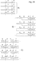
- Mechanismus (100) nach Anspruch 1, dadurch gekennzeichnet, dass der Anker (1) einen geschlossenen Zyklus ausführt, in dem das mindestens eine flexible Blatt (10), das ein bistabiles Blatt ist, nacheinander vier Hauptkonfigurationen einnimmt:- nach dem Aufladen von Energie durch das Hemmungsrad (20) und während einer Übergangsphase bei hoher Energie nähert sich das Blatt (10) einem ersten Energiesattelpunkt (CE1) mit einem Z-förmigen Wellenprofil (54) an;- nach dem Freisetzen der Energie, die dem bistabilen Blatt (10) zur Verfügung steht, bei einem Durchlaufen des ersten Energiesattelpunkts (CE1) in Form eines auf die Unruh (30) in einem ersten Richtungssinn ausgeübten Impulses, nimmt das Blatt (10) eine zweite stabile Position (PS2) bei niedriger Energie mit einem konvexen Bogenprofil (51) ein;- nach dem Aufladen von Energie durch das Hemmungsrad (20) und während einer Übergangsphase bei hoher Energie nähert sich das Blatt (10) einem zweiten Energiesattelpunkt (CE2) mit einem S-förmigen Wellenprofil (53) an;- nach dem Freisetzen der Energie, die dem bistabilen Blatt (10) zur Verfügung steht, bei einem Durchlaufen des zweiten Energiesattelpunkts (CE2) in Form eines auf die Unruh (30) in einem zweiten Richtungssinn entgegengesetzt zu dem ersten Richtungssinn ausgeübten Impulses, nimmt das Blatt (10) eine erste stabile Position (PS1) bei niedriger Energie mit einem konkaven Bogenprofil (52) ein.
- Mechanismus (100) nach Anspruch 2, dadurch gekennzeichnet, dass er Anschläge aufweist, die derart angeordnet sind, dass sie das bistabile Blatt (10) vor dem ersten (CE1) oder dem zweiten (CE2) Energiesattelpunkt, beim Spannen durch Aufladen des bistabilen Blatts (10) mit Energie anhalten.
- Mechanismus (100) nach Anspruch 3, dadurch gekennzeichnet, dass Anschläge, die den Winkelausschlag des Kopfes (2) bzw. der Gabel (6) begrenzen, beweglich sind und durch Oberflächen der Gabel (6) bzw. des Kopfes (2) gebildet sind.
- Mechanismus (100) nach Anspruch 4, dadurch gekennzeichnet, dass der Winkelausschlag des Kopfes (2) durch Anschläge begrenzt ist, die durch zwei zweite Arme (17A; 17B) gebildet sind, die die Gabel (6) aufweist.
- Mechanismus (100) nach einem der Ansprüche 1 bis 5, dadurch gekennzeichnet, dass die Gabel (6) direkt an dem bistabilen flexiblen Blatt (10) fest montiert ist, wodurch sichergestellt wird, dass nur die Gabel (6) in Bezug auf die Unruh (30) schwenkt, und dass die Bahn der Gabel (6) in Bezug auf eine erste Schwenkachse (5), um die der Kopf (2) schwenkt, durch ein Begrenzungselement (71) begrenzt ist, das mit dem Kopf (2) oder mit der Platte (40) fest verbunden ist, derart, dass dieses bistabile Blatt (10) in seinem gesamten Nutzungsbereich vorgespannt bleibt.
- Mechanismus (100) nach einem der Ansprüche 1 bis 6, dadurch gekennzeichnet, dass die Platte (40) Begrenzungsstifte (41) in der Nähe einer Rolle (31) der Unruh (30) aufweist und dass der Anker (1) verbunden ist mit der Platte einerseits auf Höhe einer ersten Schwenkachse (5), um die der Kopf (2) entweder über eine erste Drehwelle (63), sofern die Führung des Kopfes (2) klassisch durch Drehzapfen und Lager erfolgt, oder über eine erste feste Verbindung (65) schwenkt, sofern der Kopf (2) eine flexible Führung mit einem ersten flexiblen Drehzapfen (61) aufweist, und andererseits auf Höhe einer zweiten Achse (9), um die die Gabel (6) entweder über eine zweite Drehwelle (64), sofern die Führung der Gabel (6) klassisch mit Drehzapfen und Lager erfolgt, oder über eine zweite feste Verbindung (66) schwenkt, wenn die Gabel (6) eine flexible Führung mit einem zweiten flexiblen Drehzapfen (62) aufweist.
- Mechanismus (100) nach Anspruch 7, dadurch gekennzeichnet, dass die Platte (40) einerseits einen ersten Stein (42) oder eine erste Achse (43) in einer festen Position zur Schwenkführung des Kopfes (2) oder der Gabel (6) und andererseits einen zweiten Stein (44) oder eine zweite Achse (45) zur Schwenkführung der Gabel (6) bzw. des Kopfes (2) umfasst.
- Mechanismus (100) nach Anspruch 7, dadurch gekennzeichnet, dass sich der zweite Stein (44) oder die zweite Achse (45) in einer festen Position in Bezug auf den ersten Stein (42) oder die erste Achse (43) befindet.
- Mechanismus (100) nach Anspruch 7, dadurch gekennzeichnet, dass der zweite Stein (44) oder die zweite Achse (45) in eine variable Position in Bezug auf die Platte (40) geführt wird und der Wirkung zweiter elastischer Rückstellmittel (47) unterliegt.
- Mechanismus (100) nach Anspruch 7, dadurch gekennzeichnet, dass die Platte (40) einerseits einen ersten Stein (42) oder eine erste Achse (43), die in eine veränderliche Position in Bezug auf die Platte (40) geführt wird und der Wirkung erster elastischer Rückstellmittel (46) zur Schwenkführung des Kopfes (2) oder der Gabel (6) unterliegt, und andererseits einen zweiten Stein (44) oder eine zweite Achse (45) umfasst, die translatorisch in eine veränderliche Position in Bezug auf die Platte (40) geführt wird und der Wirkung zweiter elastischer Rückstellmittel (47) zur Schwenkführung der Gabel (6) bzw. des Kopfes (2) unterliegt.
- Mechanismus (100) nach einem der Ansprüche 7 bis 11, dadurch gekennzeichnet, dass die Schwenkachse (23) des Hemmungsrades (20), die Schwenkachse (32) der Unruh (30), der erste Stein (42) bzw. die erste Achse (43) und der zweite Stein (44) bzw. die zweite Achse (45) aufeinander ausgerichtet sind.
- Mechanismus (100) nach einem der Ansprüche 1 bis 12, dadurch gekennzeichnet, dass der Anker (1) für seine Befestigung an der Platte (40) erste, vom Kopf (2) getragene Befestigungs- und/oder Führungsmittel und zweite, von der Gabel (6) getragene Befestigungs- und/oder Führungsmittel umfasst.
- Mechanismus (100) nach einem der Ansprüche 1 bis 13, dadurch gekennzeichnet, dass der Ankerkopf (2) in Bezug auf eine erste Schwenkachse (5) beweglich ist oder um die erste Schwenkachse (5) schwenkt und dass die Gabel (6) in Bezug auf eine zweite Schwenkachse (9) beweglich ist oder um die zweite Schwenkachse (9), die von der ersten Achse (5) verschieden ist, schwenkt.
- Mechanismus (100) nach einem der Ansprüche 1 bis 12, dadurch gekennzeichnet, dass der Anker (1) mit dem mindestens einem flexiblen Blatt (10) einteilig ausgebildet ist.
- Mechanismus (100) nach Anspruch 15, dadurch gekennzeichnet, dass der Anker (1) aus Silicium oder Siliciumoxid oder amorphem Metall oder Nickel-Phosphor nach LIGA-Prozess hergestellt ist.
- Mechanismus (100) nach Anspruch 14 und einem der Ansprüche 15 oder 16, dadurch gekennzeichnet, dass der Anker einen ersten flexiblen (61) oder virtuellen Drehzapfen und/oder einen zweiten flexiblen (62) oder virtuellen Drehzapfen umfasst, die auf Höhe der ersten Achse (5) und/oder der zweiten Achse (9) eine flexible Führung bilden.
- Mechanismus (100) nach Anspruch 17, dadurch gekennzeichnet, dass der Anker (1) einen ersten flexiblen (61) oder virtuellen Drehzapfen und einen zweiten flexiblen (62) oder virtuellen Drehzapfen an den beiden Enden (101, 102) des mindestens einen flexiblen Blatts (10) umfasst, die jeweils eine flexible Führung auf Höhe der ersten Achse (5) bzw. der zweiten Achse (9) bilden.
- Mechanismus (100) nach einem der Ansprüche 1 bis 18, dadurch gekennzeichnet, dass die Gabel (6) einen Sicherheitsstift (7) und Hörner (8) zum Zusammenwirken mit einem Unruh (30) umfasst.
- Mechanismus (100) nach einem der Ansprüche 1 bis 19, dadurch gekennzeichnet, dass der Anker (1) in einer Kassette vormontiert ist, in der das mindestens eine flexible Blatt (10) bereits vorab vorgespannt worden ist, derart, dass der Anker (1) bistabil ist, wobei die Kassette ein Zentrierungs- und/oder Befestigungsmittel auf einer Platte aufweist.
- Uhrwerk (200), umfassend mindestens einen Hemmungsmechanismus (100) nach einem der Ansprüche 1 bis 20.
- Zeitmessgerät (300), umfassend mindestens ein Uhrwerk (200) nach Anspruch 21.
Priority Applications (1)
| Application Number | Priority Date | Filing Date | Title |
|---|---|---|---|
| EP13756165.0A EP2893403B1 (de) | 2012-09-07 | 2013-09-03 | Flexibler anker mit konstanter kraft |
Applications Claiming Priority (3)
| Application Number | Priority Date | Filing Date | Title |
|---|---|---|---|
| EP12183559.9A EP2706416B1 (de) | 2012-09-07 | 2012-09-07 | Flexibler Anker mit konstanter Kraft |
| EP13756165.0A EP2893403B1 (de) | 2012-09-07 | 2013-09-03 | Flexibler anker mit konstanter kraft |
| PCT/EP2013/068130 WO2014037319A1 (fr) | 2012-09-07 | 2013-09-03 | Ancre flexible à force constante |
Publications (2)
| Publication Number | Publication Date |
|---|---|
| EP2893403A1 EP2893403A1 (de) | 2015-07-15 |
| EP2893403B1 true EP2893403B1 (de) | 2019-08-28 |
Family
ID=46924267
Family Applications (2)
| Application Number | Title | Priority Date | Filing Date |
|---|---|---|---|
| EP12183559.9A Active EP2706416B1 (de) | 2012-09-07 | 2012-09-07 | Flexibler Anker mit konstanter Kraft |
| EP13756165.0A Active EP2893403B1 (de) | 2012-09-07 | 2013-09-03 | Flexibler anker mit konstanter kraft |
Family Applications Before (1)
| Application Number | Title | Priority Date | Filing Date |
|---|---|---|---|
| EP12183559.9A Active EP2706416B1 (de) | 2012-09-07 | 2012-09-07 | Flexibler Anker mit konstanter Kraft |
Country Status (7)
| Country | Link |
|---|---|
| US (2) | US9594349B2 (de) |
| EP (2) | EP2706416B1 (de) |
| JP (1) | JP5959750B2 (de) |
| KR (1) | KR101775249B1 (de) |
| CN (2) | CN107390494B (de) |
| HK (1) | HK1212047A1 (de) |
| WO (1) | WO2014037319A1 (de) |
Families Citing this family (22)
| Publication number | Priority date | Publication date | Assignee | Title |
|---|---|---|---|---|
| EP2947522B1 (de) | 2014-05-20 | 2017-05-03 | Société anonyme de la Manufacture d'Horlogerie Audemars Piguet & Cie | Uhranker für mechanischen Oszillator, und Mechanismus zur Zeitauslösung der Uhr |
| EP3035127B1 (de) * | 2014-12-18 | 2017-08-23 | The Swatch Group Research and Development Ltd. | Stimmgabeloszillator einer stimmgabelgesteuerten Uhr |
| EP3040783B1 (de) * | 2014-12-22 | 2017-07-26 | Manufacture et fabrique de montres et chronomètres Ulysse Nardin Le Locle SA | Untereinheit für einen mechanismus zur einstellung der geschwindigkeit in einem uhrwerk, und ein solcher mechanismus |
| WO2016113704A2 (de) | 2015-01-16 | 2016-07-21 | Creaditive Ag | Uhr, regelorgan und verfahren zum betreiben eines regelorgans mit hoher regelgüte |
| EP3185083B1 (de) * | 2015-12-23 | 2018-11-14 | Montres Breguet S.A. | Mechanischer uhrmechanismus mit einer ankerhemmung |
| FR3048791B1 (fr) * | 2016-03-14 | 2018-05-18 | Lvmh Swiss Manufactures Sa | Mecanisme pour piece d'horlogerie et piece d'horlogerie comprenant un tel mecanisme |
| CH712715B1 (fr) * | 2016-07-18 | 2020-06-30 | Sowind SA | Mécanisme d'échappement mettant en oeuvre un ressort-lame travaillant en flambage. |
| EP3273308B1 (de) * | 2016-07-18 | 2019-06-12 | Sowind S.A. | Hemmungsmechanismus |
| CH713143A1 (fr) * | 2016-11-17 | 2018-05-31 | Richemont Int Sa | Échappement pour pièce d'horlogerie. |
| EP3327515B1 (de) * | 2016-11-23 | 2020-05-06 | ETA SA Manufacture Horlogère Suisse | Sich drehender resonator mit einer flexiblen führung, der von einer freien ankerhemmung gehalten wird |
| CH713288A1 (fr) | 2016-12-23 | 2018-06-29 | Sa De La Manufacture Dhorlogerie Audemars Piguet & Cie | Composant monolithique flexible pour pièce d'horlogerie. |
| CN106986297A (zh) * | 2017-04-28 | 2017-07-28 | 茹朝贵 | 一种减震设备 |
| US11517664B2 (en) * | 2017-07-20 | 2022-12-06 | Flex Ltd. | Wire and pulley clock mechanism flow regulator |
| EP3435170B1 (de) * | 2017-07-28 | 2021-06-30 | The Swatch Group Research and Development Ltd | Uhrwerkoszillator mit flexiblen führungen mit grosser winkelförmiger laufbahn |
| EP3489763B1 (de) * | 2017-11-22 | 2021-06-16 | Nivarox-FAR S.A. | Anker für die bewegungshemmung eines uhrwerks |
| EP3492996B1 (de) | 2017-12-04 | 2020-09-02 | Patek Philippe SA Genève | Uhrhemmung mit bistabiler lamelle |
| EP3502289B1 (de) * | 2017-12-21 | 2022-11-09 | Nivarox-FAR S.A. | Herstellungsverfahren einer spiralfeder für uhrwerk |
| US10895845B2 (en) * | 2018-06-25 | 2021-01-19 | The Swatch Group Research And Development Ltd | Timepiece oscillator with flexure bearings having a long angular stroke |
| US11740589B2 (en) * | 2018-07-19 | 2023-08-29 | Werner Janer | Multi-cam, continuous-drive escapement mechanism |
| CH715864B1 (fr) * | 2019-02-19 | 2022-08-15 | Richemont Int Sa | Organe de blocage pour un mouvement horloger. |
| EP3907563B1 (de) * | 2020-05-07 | 2022-09-14 | Patek Philippe SA Genève | Uhrwerkmechanismus, das ein schwenkorgan umfasst |
| WO2023126174A1 (en) | 2021-12-29 | 2023-07-06 | Asml Netherlands B.V. | Enhanced alignment for a photolithographic apparatus |
Citations (1)
| Publication number | Priority date | Publication date | Assignee | Title |
|---|---|---|---|---|
| WO2011120180A1 (fr) * | 2010-04-01 | 2011-10-06 | Rolex S.A. | Dispositif de blocage pour roue dentée |
Family Cites Families (19)
| Publication number | Priority date | Publication date | Assignee | Title |
|---|---|---|---|---|
| DD36894B (de) * | ||||
| CH321184A (fr) * | 1955-02-25 | 1957-04-30 | Far Fab Assortiments Reunies | Plateau de balancier pour assortiment à ancre et procédé de fabrication de ce plateau |
| EP2282240B1 (de) * | 2004-10-26 | 2012-05-09 | LVMH Swiss Manufactures SA | Chronographmodul für Armbanduhr |
| EP1710636A1 (de) | 2005-04-06 | 2006-10-11 | Daniel Rochat | Hemmung für eine Uhr |
| EP1770452A1 (de) | 2005-09-30 | 2007-04-04 | Peter Baumberger | Chronometerhemmung für Uhren |
| EP1837721A1 (de) * | 2006-03-24 | 2007-09-26 | ETA SA Manufacture Horlogère Suisse | Mikromechanisches Bauteil aus Isoliermaterial und Herstellungsverfahren dafür |
| DE602007001230D1 (de) | 2007-03-09 | 2009-07-16 | Eta Sa Mft Horlogere Suisse | Hemmung mit Tangentialimpulsen |
| FR2928015B1 (fr) * | 2008-02-22 | 2010-02-19 | Jean Paul Lenoble | Echappement perfectionne a ancre articulee a impulsion tangentielle, montre mecanique |
| EP2105806B1 (de) | 2008-03-27 | 2013-11-13 | Sowind S.A. | Hemmungsmechanismus |
| JP5462006B2 (ja) | 2009-02-17 | 2014-04-02 | セイコーインスツル株式会社 | 脱進調速機、機械式時計、及びアンクル体の製造方法 |
| JP5366318B2 (ja) * | 2009-09-14 | 2013-12-11 | セイコーインスツル株式会社 | デテント脱進機およびデテント脱進機の作動レバーの製造方法 |
| CH701921B1 (fr) * | 2009-10-09 | 2014-07-31 | Télôs Watch SA | Echappement à ancre et pièce d'horlogerie comportant un tel échappement. |
| IT1396734B1 (it) * | 2009-11-25 | 2012-12-14 | Ferrara | Scappamento per orologeria ad alto rendimento. |
| CH703333B1 (fr) * | 2010-06-22 | 2015-07-15 | Bruno Fragnière | Ancre d'échappement. |
| WO2012010408A1 (fr) * | 2010-07-19 | 2012-01-26 | Nivarox-Far S.A. | Mecanisme oscillant a pivot elastique et mobile de transmission d'energie |
| EP2455821B2 (de) | 2010-11-18 | 2018-11-14 | Nivarox-FAR S.A. | Energieübertragungrad |
| EP2431823A1 (de) * | 2010-09-16 | 2012-03-21 | Blancpain S.A. | Blancpain-Hemmung mit verbessertem Anker für Uhrwerk |
| ES2770334T3 (es) * | 2010-10-21 | 2020-07-01 | Audemars Piguet (Renaud Et Papi) Sa | Mecanismo regulador para pieza de relojería |
| EP2450757B1 (de) | 2010-11-04 | 2014-10-15 | Nivarox-FAR S.A. | Antischwingungsvorrichtung für Uhrenhemmungsmechanismus |
-
2012
- 2012-09-07 EP EP12183559.9A patent/EP2706416B1/de active Active
-
2013
- 2013-09-03 JP JP2015530359A patent/JP5959750B2/ja active Active
- 2013-09-03 US US14/426,616 patent/US9594349B2/en active Active
- 2013-09-03 EP EP13756165.0A patent/EP2893403B1/de active Active
- 2013-09-03 CN CN201710730116.4A patent/CN107390494B/zh active Active
- 2013-09-03 CN CN201380058120.0A patent/CN104769508B/zh active Active
- 2013-09-03 KR KR1020157008752A patent/KR101775249B1/ko active IP Right Grant
- 2013-09-03 WO PCT/EP2013/068130 patent/WO2014037319A1/fr active Application Filing
-
2015
- 2015-12-29 HK HK15112787.5A patent/HK1212047A1/xx unknown
-
2017
- 2017-01-18 US US15/409,037 patent/US9927772B2/en active Active
Patent Citations (1)
| Publication number | Priority date | Publication date | Assignee | Title |
|---|---|---|---|---|
| WO2011120180A1 (fr) * | 2010-04-01 | 2011-10-06 | Rolex S.A. | Dispositif de blocage pour roue dentée |
Also Published As
| Publication number | Publication date |
|---|---|
| US20170131683A1 (en) | 2017-05-11 |
| WO2014037319A1 (fr) | 2014-03-13 |
| EP2706416A1 (de) | 2014-03-12 |
| JP5959750B2 (ja) | 2016-08-02 |
| KR101775249B1 (ko) | 2017-09-05 |
| US9927772B2 (en) | 2018-03-27 |
| EP2893403A1 (de) | 2015-07-15 |
| JP2015531476A (ja) | 2015-11-02 |
| US20150248112A1 (en) | 2015-09-03 |
| CN107390494A (zh) | 2017-11-24 |
| US9594349B2 (en) | 2017-03-14 |
| CN104769508B (zh) | 2018-04-13 |
| EP2706416B1 (de) | 2015-11-18 |
| WO2014037319A4 (fr) | 2014-05-08 |
| KR20150053791A (ko) | 2015-05-18 |
| CN104769508A (zh) | 2015-07-08 |
| CN107390494B (zh) | 2019-05-21 |
| HK1212047A1 (en) | 2016-06-03 |
Similar Documents
| Publication | Publication Date | Title |
|---|---|---|
| EP2893403B1 (de) | Flexibler anker mit konstanter kraft | |
| EP2831677B1 (de) | Flexibler uhrhemmungsmechanismus | |
| EP2553533B2 (de) | Blockiervorrichtung für Zahnrad | |
| EP3545365B1 (de) | Sich drehender resonator mit einer flexiblen führung, der von einer freien ankerhemmung gehalten wird | |
| EP2730980B1 (de) | Uhrmechanismus zur Begrenzung oder Übertragung | |
| EP2224292B1 (de) | Chronometerhemmung für Uhrwerk | |
| CH706274B1 (fr) | Mécanisme d'échappement horloger comprenant un mécanisme flexible monobloc pour la transmission d'impulsions entre le balancier et la roue d'échappement. | |
| WO2009118310A1 (fr) | Mécanisme d'échappement | |
| EP3054356B1 (de) | Isochroner Resonator für Uhr | |
| CH705814B1 (fr) | Echappement à ancre pour mouvement d'horlogerie. | |
| EP3037894B1 (de) | Mechanismus und Verfahren zur Geschwindigkeitseinstellung in einem Uhrwerk | |
| EP3627242B1 (de) | Optimierter magnetomechanischer uhrhemmungsmechanismus | |
| CH706924A2 (fr) | Ancre flexible à force constante et échappement muni d'une telle ancre. | |
| EP3338144B1 (de) | Bistabile mechanische vorrichtung für uhrwerke | |
| EP3510449B1 (de) | Hemmungsmechanismus | |
| WO2017102917A1 (fr) | Oscillateur mécanique pour pièce d'horlogerie, mécanisme de réglage comportant cet oscillateur mécanique, et mouvement d'horlogerie | |
| EP3185083B1 (de) | Mechanischer uhrmechanismus mit einer ankerhemmung | |
| CH714361A2 (fr) | Résonateur rotatif à guidage flexible entretenu par un échappement libre à ancre. | |
| EP3475765B1 (de) | Uhrwerkshemmung | |
| CH715356A2 (fr) | Mécanisme d'échappement d'horlogerie magnéto-mécanique. | |
| EP4191346B1 (de) | Stossdämpfungsschutz eines resonatormechanismus mit flexibler drehführung | |
| EP3479175B1 (de) | Mechanisches uhrwerk | |
| CH719206A2 (fr) | Mécanisme résonateur d'horlogerie à guidage flexible rotatif. |
Legal Events
| Date | Code | Title | Description |
|---|---|---|---|
| PUAI | Public reference made under article 153(3) epc to a published international application that has entered the european phase |
Free format text: ORIGINAL CODE: 0009012 |
|
| 17P | Request for examination filed |
Effective date: 20150407 |
|
| AK | Designated contracting states |
Kind code of ref document: A1 Designated state(s): AL AT BE BG CH CY CZ DE DK EE ES FI FR GB GR HR HU IE IS IT LI LT LU LV MC MK MT NL NO PL PT RO RS SE SI SK SM TR |
|
| AX | Request for extension of the european patent |
Extension state: BA ME |
|
| DAX | Request for extension of the european patent (deleted) | ||
| STAA | Information on the status of an ep patent application or granted ep patent |
Free format text: STATUS: EXAMINATION IS IN PROGRESS |
|
| 17Q | First examination report despatched |
Effective date: 20170518 |
|
| GRAP | Despatch of communication of intention to grant a patent |
Free format text: ORIGINAL CODE: EPIDOSNIGR1 |
|
| STAA | Information on the status of an ep patent application or granted ep patent |
Free format text: STATUS: GRANT OF PATENT IS INTENDED |
|
| INTG | Intention to grant announced |
Effective date: 20181109 |
|
| GRAJ | Information related to disapproval of communication of intention to grant by the applicant or resumption of examination proceedings by the epo deleted |
Free format text: ORIGINAL CODE: EPIDOSDIGR1 |
|
| STAA | Information on the status of an ep patent application or granted ep patent |
Free format text: STATUS: EXAMINATION IS IN PROGRESS |
|
| INTC | Intention to grant announced (deleted) | ||
| GRAS | Grant fee paid |
Free format text: ORIGINAL CODE: EPIDOSNIGR3 |
|
| STAA | Information on the status of an ep patent application or granted ep patent |
Free format text: STATUS: GRANT OF PATENT IS INTENDED |
|
| GRAP | Despatch of communication of intention to grant a patent |
Free format text: ORIGINAL CODE: EPIDOSNIGR1 |
|
| INTG | Intention to grant announced |
Effective date: 20190418 |
|
| GRAA | (expected) grant |
Free format text: ORIGINAL CODE: 0009210 |
|
| STAA | Information on the status of an ep patent application or granted ep patent |
Free format text: STATUS: THE PATENT HAS BEEN GRANTED |
|
| AK | Designated contracting states |
Kind code of ref document: B1 Designated state(s): AL AT BE BG CH CY CZ DE DK EE ES FI FR GB GR HR HU IE IS IT LI LT LU LV MC MK MT NL NO PL PT RO RS SE SI SK SM TR |
|
| REG | Reference to a national code |
Ref country code: GB Ref legal event code: FG4D Free format text: NOT ENGLISH |
|
| REG | Reference to a national code |
Ref country code: CH Ref legal event code: EP |
|
| REG | Reference to a national code |
Ref country code: CH Ref legal event code: NV Representative=s name: ICB INGENIEURS CONSEILS EN BREVETS SA, CH |
|
| REG | Reference to a national code |
Ref country code: AT Ref legal event code: REF Ref document number: 1173154 Country of ref document: AT Kind code of ref document: T Effective date: 20190915 |
|
| REG | Reference to a national code |
Ref country code: IE Ref legal event code: FG4D Free format text: LANGUAGE OF EP DOCUMENT: FRENCH |
|
| REG | Reference to a national code |
Ref country code: DE Ref legal event code: R096 Ref document number: 602013059746 Country of ref document: DE |
|
| REG | Reference to a national code |
Ref country code: NL Ref legal event code: MP Effective date: 20190828 |
|
| REG | Reference to a national code |
Ref country code: LT Ref legal event code: MG4D |
|
| PG25 | Lapsed in a contracting state [announced via postgrant information from national office to epo] |
Ref country code: HR Free format text: LAPSE BECAUSE OF FAILURE TO SUBMIT A TRANSLATION OF THE DESCRIPTION OR TO PAY THE FEE WITHIN THE PRESCRIBED TIME-LIMIT Effective date: 20190828 Ref country code: NL Free format text: LAPSE BECAUSE OF FAILURE TO SUBMIT A TRANSLATION OF THE DESCRIPTION OR TO PAY THE FEE WITHIN THE PRESCRIBED TIME-LIMIT Effective date: 20190828 Ref country code: PT Free format text: LAPSE BECAUSE OF FAILURE TO SUBMIT A TRANSLATION OF THE DESCRIPTION OR TO PAY THE FEE WITHIN THE PRESCRIBED TIME-LIMIT Effective date: 20191230 Ref country code: SE Free format text: LAPSE BECAUSE OF FAILURE TO SUBMIT A TRANSLATION OF THE DESCRIPTION OR TO PAY THE FEE WITHIN THE PRESCRIBED TIME-LIMIT Effective date: 20190828 Ref country code: BG Free format text: LAPSE BECAUSE OF FAILURE TO SUBMIT A TRANSLATION OF THE DESCRIPTION OR TO PAY THE FEE WITHIN THE PRESCRIBED TIME-LIMIT Effective date: 20191128 Ref country code: LT Free format text: LAPSE BECAUSE OF FAILURE TO SUBMIT A TRANSLATION OF THE DESCRIPTION OR TO PAY THE FEE WITHIN THE PRESCRIBED TIME-LIMIT Effective date: 20190828 Ref country code: FI Free format text: LAPSE BECAUSE OF FAILURE TO SUBMIT A TRANSLATION OF THE DESCRIPTION OR TO PAY THE FEE WITHIN THE PRESCRIBED TIME-LIMIT Effective date: 20190828 Ref country code: NO Free format text: LAPSE BECAUSE OF FAILURE TO SUBMIT A TRANSLATION OF THE DESCRIPTION OR TO PAY THE FEE WITHIN THE PRESCRIBED TIME-LIMIT Effective date: 20191128 |
|
| PG25 | Lapsed in a contracting state [announced via postgrant information from national office to epo] |
Ref country code: IS Free format text: LAPSE BECAUSE OF FAILURE TO SUBMIT A TRANSLATION OF THE DESCRIPTION OR TO PAY THE FEE WITHIN THE PRESCRIBED TIME-LIMIT Effective date: 20191228 Ref country code: RS Free format text: LAPSE BECAUSE OF FAILURE TO SUBMIT A TRANSLATION OF THE DESCRIPTION OR TO PAY THE FEE WITHIN THE PRESCRIBED TIME-LIMIT Effective date: 20190828 Ref country code: GR Free format text: LAPSE BECAUSE OF FAILURE TO SUBMIT A TRANSLATION OF THE DESCRIPTION OR TO PAY THE FEE WITHIN THE PRESCRIBED TIME-LIMIT Effective date: 20191129 Ref country code: ES Free format text: LAPSE BECAUSE OF FAILURE TO SUBMIT A TRANSLATION OF THE DESCRIPTION OR TO PAY THE FEE WITHIN THE PRESCRIBED TIME-LIMIT Effective date: 20190828 Ref country code: AL Free format text: LAPSE BECAUSE OF FAILURE TO SUBMIT A TRANSLATION OF THE DESCRIPTION OR TO PAY THE FEE WITHIN THE PRESCRIBED TIME-LIMIT Effective date: 20190828 Ref country code: LV Free format text: LAPSE BECAUSE OF FAILURE TO SUBMIT A TRANSLATION OF THE DESCRIPTION OR TO PAY THE FEE WITHIN THE PRESCRIBED TIME-LIMIT Effective date: 20190828 |
|
| REG | Reference to a national code |
Ref country code: AT Ref legal event code: MK05 Ref document number: 1173154 Country of ref document: AT Kind code of ref document: T Effective date: 20190828 |
|
| PG25 | Lapsed in a contracting state [announced via postgrant information from national office to epo] |
Ref country code: TR Free format text: LAPSE BECAUSE OF FAILURE TO SUBMIT A TRANSLATION OF THE DESCRIPTION OR TO PAY THE FEE WITHIN THE PRESCRIBED TIME-LIMIT Effective date: 20190828 |
|
| PG25 | Lapsed in a contracting state [announced via postgrant information from national office to epo] |
Ref country code: DK Free format text: LAPSE BECAUSE OF FAILURE TO SUBMIT A TRANSLATION OF THE DESCRIPTION OR TO PAY THE FEE WITHIN THE PRESCRIBED TIME-LIMIT Effective date: 20190828 Ref country code: EE Free format text: LAPSE BECAUSE OF FAILURE TO SUBMIT A TRANSLATION OF THE DESCRIPTION OR TO PAY THE FEE WITHIN THE PRESCRIBED TIME-LIMIT Effective date: 20190828 Ref country code: AT Free format text: LAPSE BECAUSE OF FAILURE TO SUBMIT A TRANSLATION OF THE DESCRIPTION OR TO PAY THE FEE WITHIN THE PRESCRIBED TIME-LIMIT Effective date: 20190828 Ref country code: IT Free format text: LAPSE BECAUSE OF FAILURE TO SUBMIT A TRANSLATION OF THE DESCRIPTION OR TO PAY THE FEE WITHIN THE PRESCRIBED TIME-LIMIT Effective date: 20190828 Ref country code: RO Free format text: LAPSE BECAUSE OF FAILURE TO SUBMIT A TRANSLATION OF THE DESCRIPTION OR TO PAY THE FEE WITHIN THE PRESCRIBED TIME-LIMIT Effective date: 20190828 Ref country code: PL Free format text: LAPSE BECAUSE OF FAILURE TO SUBMIT A TRANSLATION OF THE DESCRIPTION OR TO PAY THE FEE WITHIN THE PRESCRIBED TIME-LIMIT Effective date: 20190828 |
|
| PG25 | Lapsed in a contracting state [announced via postgrant information from national office to epo] |
Ref country code: IS Free format text: LAPSE BECAUSE OF FAILURE TO SUBMIT A TRANSLATION OF THE DESCRIPTION OR TO PAY THE FEE WITHIN THE PRESCRIBED TIME-LIMIT Effective date: 20200224 Ref country code: SM Free format text: LAPSE BECAUSE OF FAILURE TO SUBMIT A TRANSLATION OF THE DESCRIPTION OR TO PAY THE FEE WITHIN THE PRESCRIBED TIME-LIMIT Effective date: 20190828 Ref country code: SK Free format text: LAPSE BECAUSE OF FAILURE TO SUBMIT A TRANSLATION OF THE DESCRIPTION OR TO PAY THE FEE WITHIN THE PRESCRIBED TIME-LIMIT Effective date: 20190828 Ref country code: MC Free format text: LAPSE BECAUSE OF FAILURE TO SUBMIT A TRANSLATION OF THE DESCRIPTION OR TO PAY THE FEE WITHIN THE PRESCRIBED TIME-LIMIT Effective date: 20190828 Ref country code: CZ Free format text: LAPSE BECAUSE OF FAILURE TO SUBMIT A TRANSLATION OF THE DESCRIPTION OR TO PAY THE FEE WITHIN THE PRESCRIBED TIME-LIMIT Effective date: 20190828 |
|
| REG | Reference to a national code |
Ref country code: DE Ref legal event code: R097 Ref document number: 602013059746 Country of ref document: DE |
|
| PLBE | No opposition filed within time limit |
Free format text: ORIGINAL CODE: 0009261 |
|
| STAA | Information on the status of an ep patent application or granted ep patent |
Free format text: STATUS: NO OPPOSITION FILED WITHIN TIME LIMIT |
|
| PG2D | Information on lapse in contracting state deleted |
Ref country code: IS |
|
| PG25 | Lapsed in a contracting state [announced via postgrant information from national office to epo] |
Ref country code: LU Free format text: LAPSE BECAUSE OF NON-PAYMENT OF DUE FEES Effective date: 20190903 Ref country code: IE Free format text: LAPSE BECAUSE OF NON-PAYMENT OF DUE FEES Effective date: 20190903 |
|
| REG | Reference to a national code |
Ref country code: BE Ref legal event code: MM Effective date: 20190930 |
|
| 26N | No opposition filed |
Effective date: 20200603 |
|
| PG25 | Lapsed in a contracting state [announced via postgrant information from national office to epo] |
Ref country code: BE Free format text: LAPSE BECAUSE OF NON-PAYMENT OF DUE FEES Effective date: 20190930 Ref country code: SI Free format text: LAPSE BECAUSE OF FAILURE TO SUBMIT A TRANSLATION OF THE DESCRIPTION OR TO PAY THE FEE WITHIN THE PRESCRIBED TIME-LIMIT Effective date: 20190828 |
|
| PG25 | Lapsed in a contracting state [announced via postgrant information from national office to epo] |
Ref country code: CY Free format text: LAPSE BECAUSE OF FAILURE TO SUBMIT A TRANSLATION OF THE DESCRIPTION OR TO PAY THE FEE WITHIN THE PRESCRIBED TIME-LIMIT Effective date: 20190828 |
|
| PG25 | Lapsed in a contracting state [announced via postgrant information from national office to epo] |
Ref country code: MT Free format text: LAPSE BECAUSE OF FAILURE TO SUBMIT A TRANSLATION OF THE DESCRIPTION OR TO PAY THE FEE WITHIN THE PRESCRIBED TIME-LIMIT Effective date: 20190828 Ref country code: HU Free format text: LAPSE BECAUSE OF FAILURE TO SUBMIT A TRANSLATION OF THE DESCRIPTION OR TO PAY THE FEE WITHIN THE PRESCRIBED TIME-LIMIT; INVALID AB INITIO Effective date: 20130903 |
|
| PG25 | Lapsed in a contracting state [announced via postgrant information from national office to epo] |
Ref country code: MK Free format text: LAPSE BECAUSE OF FAILURE TO SUBMIT A TRANSLATION OF THE DESCRIPTION OR TO PAY THE FEE WITHIN THE PRESCRIBED TIME-LIMIT Effective date: 20190828 |
|
| P01 | Opt-out of the competence of the unified patent court (upc) registered |
Effective date: 20230611 |
|
| PGFP | Annual fee paid to national office [announced via postgrant information from national office to epo] |
Ref country code: GB Payment date: 20230823 Year of fee payment: 11 |
|
| PGFP | Annual fee paid to national office [announced via postgrant information from national office to epo] |
Ref country code: FR Payment date: 20230822 Year of fee payment: 11 Ref country code: DE Payment date: 20230822 Year of fee payment: 11 |
|
| PGFP | Annual fee paid to national office [announced via postgrant information from national office to epo] |
Ref country code: CH Payment date: 20231001 Year of fee payment: 11 |
|
| REG | Reference to a national code |
Ref country code: DE Ref legal event code: R081 Ref document number: 602013059746 Country of ref document: DE Owner name: THE SWATCH GROUP RESEARCH AND DEVELOPMENT LTD., CH Free format text: FORMER OWNER: NIVAROX-FAR S.A., LE LOCLE, CH |
|
| REG | Reference to a national code |
Ref country code: GB Ref legal event code: 732E Free format text: REGISTERED BETWEEN 20240815 AND 20240821 |