EP2891741A2 - Trommelwaschmaschine - Google Patents
Trommelwaschmaschine Download PDFInfo
- Publication number
- EP2891741A2 EP2891741A2 EP14177066.9A EP14177066A EP2891741A2 EP 2891741 A2 EP2891741 A2 EP 2891741A2 EP 14177066 A EP14177066 A EP 14177066A EP 2891741 A2 EP2891741 A2 EP 2891741A2
- Authority
- EP
- European Patent Office
- Prior art keywords
- cabinet
- washing machine
- main body
- type washing
- drum type
- Prior art date
- Legal status (The legal status is an assumption and is not a legal conclusion. Google has not performed a legal analysis and makes no representation as to the accuracy of the status listed.)
- Granted
Links
- 238000005406 washing Methods 0.000 title claims abstract description 62
- 230000000903 blocking effect Effects 0.000 claims description 11
- 238000009434 installation Methods 0.000 claims description 5
- XLYOFNOQVPJJNP-UHFFFAOYSA-N water Substances O XLYOFNOQVPJJNP-UHFFFAOYSA-N 0.000 description 5
- 238000006073 displacement reaction Methods 0.000 description 2
- 230000004048 modification Effects 0.000 description 2
- 238000012986 modification Methods 0.000 description 2
- 208000027418 Wounds and injury Diseases 0.000 description 1
- 230000006378 damage Effects 0.000 description 1
- 230000007423 decrease Effects 0.000 description 1
- 239000003599 detergent Substances 0.000 description 1
- 230000000694 effects Effects 0.000 description 1
- 230000005484 gravity Effects 0.000 description 1
- 208000014674 injury Diseases 0.000 description 1
- 230000002452 interceptive effect Effects 0.000 description 1
- 230000007257 malfunction Effects 0.000 description 1
- 238000004519 manufacturing process Methods 0.000 description 1
- 238000000034 method Methods 0.000 description 1
- 230000035939 shock Effects 0.000 description 1
- 239000000126 substance Substances 0.000 description 1
Images



Classifications
-
- D—TEXTILES; PAPER
- D06—TREATMENT OF TEXTILES OR THE LIKE; LAUNDERING; FLEXIBLE MATERIALS NOT OTHERWISE PROVIDED FOR
- D06F—LAUNDERING, DRYING, IRONING, PRESSING OR FOLDING TEXTILE ARTICLES
- D06F39/00—Details of washing machines not specific to a single type of machines covered by groups D06F9/00 - D06F27/00
- D06F39/12—Casings; Tubs
-
- D—TEXTILES; PAPER
- D06—TREATMENT OF TEXTILES OR THE LIKE; LAUNDERING; FLEXIBLE MATERIALS NOT OTHERWISE PROVIDED FOR
- D06F—LAUNDERING, DRYING, IRONING, PRESSING OR FOLDING TEXTILE ARTICLES
- D06F37/00—Details specific to washing machines covered by groups D06F21/00 - D06F25/00
- D06F37/02—Rotary receptacles, e.g. drums
- D06F37/04—Rotary receptacles, e.g. drums adapted for rotation or oscillation about a horizontal or inclined axis
-
- D—TEXTILES; PAPER
- D06—TREATMENT OF TEXTILES OR THE LIKE; LAUNDERING; FLEXIBLE MATERIALS NOT OTHERWISE PROVIDED FOR
- D06F—LAUNDERING, DRYING, IRONING, PRESSING OR FOLDING TEXTILE ARTICLES
- D06F37/00—Details specific to washing machines covered by groups D06F21/00 - D06F25/00
- D06F37/26—Casings; Tubs
-
- D—TEXTILES; PAPER
- D06—TREATMENT OF TEXTILES OR THE LIKE; LAUNDERING; FLEXIBLE MATERIALS NOT OTHERWISE PROVIDED FOR
- D06F—LAUNDERING, DRYING, IRONING, PRESSING OR FOLDING TEXTILE ARTICLES
- D06F37/00—Details specific to washing machines covered by groups D06F21/00 - D06F25/00
- D06F37/20—Mountings, e.g. resilient mountings, for the rotary receptacle, motor, tub or casing; Preventing or damping vibrations
- D06F37/22—Mountings, e.g. resilient mountings, for the rotary receptacle, motor, tub or casing; Preventing or damping vibrations in machines with a receptacle rotating or oscillating about a horizontal axis
Definitions
- the present disclosure relates to a drum type washing machine.
- a drum type washing machine washes the laundry placed in the washing machine through a door provided at a front side of the washing machine, with relatively small amounts of water and detergent.
- the drum type washing machine may include a cabinet that defines the outer appearance of the washing machine; a tub in the cabinet configured to hold water; a rotatable drum in the tub configured to hold laundry; a motor located inside, behind or under the tub to rotate the drum, a water feeder that supplies water to the tub, and a drain configured to drain water from the tub to the outside of the cabinet after a washing operation is completed.
- the drum generally rotates about a horizontal axis.
- the door of the washing machine is at a front side of the cabinet.
- a conventional drum type washing machine may be disclosed in Korean Patent Publication No. 2006-0103977 (published on October 09, 2006 ).
- the present disclosure provides a drum type washing machine capable of readily placing laundry into a drum and removing laundry out of the drum.
- Exemplary embodiments of the present disclosure provide a drum type washing machine comprising a main body including a cabinet, a drum in the cabinet having a rotational axis thereof parallel with the ground, and a motor configured to drive or rotate the drum; and an angle adjusting unit configured to adjust an angle of the main body from the ground and/or tilt the main body up to the angle, wherein the angle adjusting unit includes a base configured to support the main body and a driver on the base configured to tilt or raise the main body, and the angle adjusting unit is configured to tilt the main body at a rear lower end of the cabinet (e.g., the main body and/or the cabinet comprises a hinge or pivot at the rear lower end of the cabinet).
- a rotational shaft (e.g., that acts as a hinge or pivot for tilting the main body) may be oriented side to side, horizontally to the ground, and/or perpendicular to a rotational axis of the drum, and the base may have a guide groove, in which the rotational shaft rotates, moves and/or slides along a front-to-rear direction of the cabinet.
- the driver may be a cylinder device (e.g., a hydraulic cylinder or other piston-based device), and the cylinder device may be spaced apart or separated from a rotational axis of the main body, so that the cylinder device may tilt the cabinet up and down (or the main body).
- a cylinder device e.g., a hydraulic cylinder or other piston-based device
- the cylinder device may be spaced apart or separated from a rotational axis of the main body, so that the cylinder device may tilt the cabinet up and down (or the main body).
- the cylinder device may include a piston configured to reciprocate bidirectionally, and an end of the piston may be connected to a lower surface or section of the cabinet that may be tilted up and down.
- the end of the piston may be connected to a hinge that may rotate, or slide forward and backward, at a lower section of the cabinet.
- the cylinder device may be rotatably connected to the base.
- the cabinet may include a front blocking plate at a front surface of the cabinet to block a front space between the cabinet and the base, and one or more side blocking plates at respective side surface(s) of the cabinet to block a side space between the cabinet and the base.
- the side blocking plate(s) may be at side surface(s) of the cabinet to cover and protect the rotational shaft.
- FIG. 1 is a perspective view of a drum type washing machine according to exemplary embodiments of the present disclosure
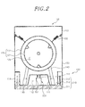
- FIG. 2 is a cross-sectional view schematically illustrating a front surface of the exemplary washing machine of FIG. 1
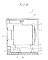
- FIG. 3 is a cross-sectional view schematically illustrating a side surface of the exemplary washing machine of FIG. 1
- FIG. 4 is a view illustrating a tilted exemplary washing machine of FIG. 3 .
- a drum type washing machine 10 includes a main body 100, an angle adjusting unit 200 and a control panel 300.
- the side having a door 123 is designated as a front side, and an opposite side thereof is designated as a rear side.
- the main body 100 may include a cabinet 110 defining an exterior of the drum type washing machine 10, and a washing unit 120 configured to wash laundry.
- the cabinet 110 serves to receive and support the washing unit 120 and thus has a shape that is capable of receiving the washing unit 120.
- the cabinet 110 may have a hexahedral shape and may include a bent or sloped surface 111 such that a part of a bottom surface of the cabinet 110 protrudes upwardly.
- an installation space 112 may be between the bent or sloped surface 111 and the base 210 such that a driver 220 of the angle adjusting unit 200 may be located inside the installation space 112.
- a front blocking plate 113 that blocks the space between the cabinet 110, when tilted, the base 210 may be at a front surface of the cabinet 110, and one or more side blocking plate(s) 114 that block a side space between the cabinet 110 and the base 210 may be provided at respective side surface(s) of the cabinet 110.
- the one or more side blocking plate(s) 114 are at a side surface of a rotational shaft 213, and may cover and/or protect the rotational shaft 213.
- the control panel 300 having buttons, knobs or the like enables a user to select a washing function or an angle adjusting function that enables the main body 100 to be pivoted upwardly or returned to its original position, may be on the front surface or an upper surface of the cabinet 110.
- the washing unit 120 is in the cabinet 110, and may include a drum 121 inside the cabinet 110, to be rotated by a motor of which a horizontal shaft extends in a front-to-rear direction, and a tub 122 configured to support and/or surround the drum 121.
- the drum 121 may be rotated horizontally about a rotational axis parallel with the ground, extending between the front surface of the main body 100 and the rear surface of the main body 100.
- the drum 121 may have a cylindrical shape of which the front surface is open, and the open front surface may be closed by the door 123 of the washing machine.
- the drum 121 has a washing space 124 in which the laundry may be washed.
- An upper surface or section of the tub 122 configured to support the drum 121 may be fixed to the cabinet 110 by an elastic fixing member 130 such as a spring, and a lower surface or section of the tub 122 may be supported by a supporting member 140.
- the supporting member 140 may be a damper that absorbs and/or reduces shocks and/or vibrations generated by rotation of the drum 121 or the like.
- the angle adjusting unit 200 having a function of adjusting an angle of the main body 100 from the ground may include a base 210 and a driver 220 configured to pivot (tilt up) the main body 100.
- a cylinder device e.g., a hydraulic cylinder or other piston-based device
- the driver 220 may comprise other drivers or driving devices such as a motor.
- the driver 220 will be referred to as the cylinder device 220.
- the base 210 defines a bottom surface of the drum type washing machine 10 and may support the main body 100.
- the base 210 may include a base plate 211 on which the main body 100 rests or is settled (e.g., in the absence of being tilted), one pair of side plates 212 at each side surface(s) of the base plate 211, and a rotational shaft 213 oriented or extending side-to-side across the cabinet and/or horizontally to the ground.
- the base 210 may be connected with the cabinet 110 through the rotational shaft 213, and the rotational shaft 213 may connect the side plates 212 and a rear lower end of the cabinet 110. Therefore, the cabinet 110 may be pivoted about the rotational shaft 213 (e.g., which acts as a hinge or pivot).
- the main body 100 may be pivoted (tilted up) around an axis located in the rear lower end of the cabinet or main body.
- the cylinder device 220 lifts the main body 100 up and down (e.g., the front end of the main body 100) so that the main body 100 may be pivoted up and down.
- the cylinder device 220 may be disposed in an installation space 112 between the base 210 and the bent or sloped surface 111.
- the cylinder device 220 includes a piston 222 which may reciprocate (e.g., drive an arm or rod that goes in and out of the cylinder).
- An end of the piston 222 and the cabinet 110 may be connected with each other through a hinge 221.
- the hinge 221 may rotate or slide forward and backward so that an angle of the main body 100 from the ground changes when the main body 100 is lifted up and down.
- a rail or slot extending in a front-to-rear direction is on or in the bottom surface of the cabinet 110, and the hinge 221 may be coupled to the rail or slot and move along the rail or slot.
- the cylinder device 220 is coupled to the bottom surface of the cabinet at a front side of the rotational shaft 213, and thus the main body 100 may pivot upwardly about the rotational shaft 213 when the piston 222 moves up.
- the tilting angle of the main body 100 from the ground increases or becomes greater, assuming a lifting displacement of the piston 222 is the same. Therefore, to increase the tilting angle of the main body 100 from the ground, the distance between the cylinder device 220 and the rotational shaft 213 should be short, and to reduce the tilting angle of the main body 100, the distance between the cylinder device 220 and the rotational shaft 213 should be long, whereby it is possible to effectively adjust the tilting angle of the main body 100 from the ground.
- the tilting angle of the main body 100 may be adjusted by increasing or reducing the lifting displacement of the piston 222.
- the main body 100 may be pivoted upwardly by controlling the control panel 130 when a user washes or collects laundry from the drum type washing machine 10.
- the main body may be pivoted upwardly by the driver 220, i.e., the cylinder device 220. More specifically, if the cylinder device 220 is driven, the piston 222 moves up and pushes the main body 100 upwardly, and the hinge 221 may rotate or slide in a predetermined distance toward the front side of the main body 100. Therefore, since an external force is applied to the main body 100 upwardly in front of the rotational shaft 231, which is a rotational center, the main body 100 pivots upwardly (e.g., in a clockwise direction of FIG. 3 ).
- the drum 121 tilts up more than before adjusting the angle of the main body 100, and the door 123 opens more upwardly than before. Therefore, the user may more conveniently open the door 123.
- the drum 124 also pivots upwardly together with the door 123, the user may open the door 123 and then may conveniently place the laundry in the drum 124 or may remove the laundry out of the drum 124.
- the user's back does not have to bend as much when the user places the laundry into the drum 124 or removes the laundry out of the drum 124, thus reducing the risk of injury and/or strain to the user's back.
- the user when the user places a large amount of the laundry in the drum 124 of a conventional drum type washing machine, the user has to push the laundry to a rear side of the drum 124 horizontally.
- the laundry naturally moves to the innermost end of the drum 124 by gravity when placing laundry into the drum 124, thus the user may easily place larger amounts of laundry into the drum 124.
- the user may operate the control panel 300 to return the main body 100 to its original position. More specifically, the cylinder device 220 may move the piston 222 down and the hinge 221 may rotate or slide to a rear side of the main body 100, and the main body 100 may be tilted down along the rotational shaft 213 in a counter-clockwise direction, and then settle on the base 210.
- a washing process of the drum type washing machine 10 is carried out when the main body 100 is settled on the base 210. At this time, since the drum 124 is rotated when the rotational axis thereof parallel with the ground, the washing process may be stably performed.
- FIG. 5 is a cross-sectional view schematically illustrating a side surface of a washing machine 10' according to other exemplary embodiments of the present disclosure.
- the drum type washing machine 10' includes the main body 100 and an angle adjusting unit 200' configured to tilting the main body 100.
- the angle adjusting unit 200' may include a base 210' that the main body is settled and a cylinder device 220' configured to lift the main body 100 up and down.
- the base 210' may be connected with the main body 100 through a rotational shaft 213' extending in a side-to-side direction between a pair of side plates 212', and the side plate 212' may have a guide groove 214 which guides the rotational shaft 213' in a horizontal forward and backward direction.
- the cylinder device 220' tilted in a forward direction may be connected with the main body 100.
- the main body 100 is lifted up accordingly.
- the main body 100 while being lifted up, moves to a forward direction and/or location together with the rotational shaft 213', as the piston moves up.
- the main body 100 pivots by the rotational shaft 213' and the rear end of the main body 100 is inclined toward the rear side, the main body 100 is prevented from interfering with an object (e.g., wall) located at the rear side of the main body 100 because the main body 100 moves to the front side.
- an object e.g., wall
- the exemplary embodiments of the present disclosure advantageously provide a drum type washing machine capable of readily placing the laundry in the drum and removing laundry out of the drum.
Landscapes
- Engineering & Computer Science (AREA)
- Textile Engineering (AREA)
- Main Body Construction Of Washing Machines And Laundry Dryers (AREA)
Applications Claiming Priority (1)
| Application Number | Priority Date | Filing Date | Title |
|---|---|---|---|
| KR1020130164185A KR101568210B1 (ko) | 2013-12-26 | 2013-12-26 | 드럼 세탁기 |
Publications (3)
| Publication Number | Publication Date |
|---|---|
| EP2891741A2 true EP2891741A2 (de) | 2015-07-08 |
| EP2891741A3 EP2891741A3 (de) | 2015-08-19 |
| EP2891741B1 EP2891741B1 (de) | 2016-11-16 |
Family
ID=51205242
Family Applications (1)
| Application Number | Title | Priority Date | Filing Date |
|---|---|---|---|
| EP14177066.9A Not-in-force EP2891741B1 (de) | 2013-12-26 | 2014-07-15 | Trommelwaschmaschine |
Country Status (4)
| Country | Link |
|---|---|
| US (1) | US9493898B2 (de) |
| EP (1) | EP2891741B1 (de) |
| KR (1) | KR101568210B1 (de) |
| CN (1) | CN104746281B (de) |
Families Citing this family (7)
| Publication number | Priority date | Publication date | Assignee | Title |
|---|---|---|---|---|
| TWM494176U (zh) * | 2014-09-11 | 2015-01-21 | jun-ting Chen | 洗衣機洗衣脫水槽轉向構造 |
| US9771676B2 (en) * | 2016-01-28 | 2017-09-26 | Wuxi Little Swan Co., Ltd. | Front-loading washing machine |
| CN107287812A (zh) * | 2017-06-05 | 2017-10-24 | 青岛海尔滚筒洗衣机有限公司 | 一种筒体可倾斜的滚筒洗衣机及控制方法 |
| CN109402970B (zh) * | 2017-08-15 | 2022-04-12 | 重庆海尔滚筒洗衣机有限公司 | 升降装置和包括升降装置的洗衣机 |
| US11618989B2 (en) | 2020-02-25 | 2023-04-04 | Whirlpool Corporation | Appliance lift system |
| CN115248571B (zh) * | 2021-04-27 | 2025-09-16 | 广东博智林机器人有限公司 | 控制方法、控制装置、控制系统和计算机设备 |
| US12098495B2 (en) * | 2022-05-23 | 2024-09-24 | Haier Us Appliance Solutions, Inc. | Mechanism for articulating washing machine appliances |
Citations (1)
| Publication number | Priority date | Publication date | Assignee | Title |
|---|---|---|---|---|
| KR20060103977A (ko) | 2005-03-29 | 2006-10-09 | 주식회사 대우일렉트로닉스 | 드럼세탁기의 세탁수 순환장치 |
Family Cites Families (8)
| Publication number | Priority date | Publication date | Assignee | Title |
|---|---|---|---|---|
| GB949845A (en) | 1960-07-27 | 1964-02-19 | James Armstrong & Co Ltd | Improvements in washing machines |
| US3199319A (en) | 1962-06-04 | 1965-08-10 | James Armstrong & Co Ltd | Washing machines |
| DE3224043C2 (de) | 1982-06-28 | 1984-06-28 | Multimatic Maschinen GmbH & Co, 4520 Melle | Trockenreinigungsvorrichtung |
| JP2000005486A (ja) * | 1998-06-17 | 2000-01-11 | Toshiba Corp | 洗濯機 |
| JP2004081733A (ja) * | 2002-08-29 | 2004-03-18 | Inamoto Seisakusho:Kk | 洗濯脱水機の運転方法 |
| DE10339604B3 (de) | 2003-08-28 | 2004-10-21 | Miele & Cie. Kg | Trommelwaschmaschine mit einer Neigevorrichtung zum Bewegen des Waschaggregats |
| KR20050045260A (ko) | 2003-11-10 | 2005-05-17 | 삼성전자주식회사 | 수위감지장치가 구비된 드럼세탁기 |
| DE202004003814U1 (de) | 2004-03-11 | 2004-05-13 | Jensen-Senking Gmbh | Wäscheschüttler |
-
2013
- 2013-12-26 KR KR1020130164185A patent/KR101568210B1/ko not_active Expired - Fee Related
-
2014
- 2014-01-31 US US14/170,492 patent/US9493898B2/en not_active Expired - Fee Related
- 2014-02-12 CN CN201410049198.2A patent/CN104746281B/zh not_active Expired - Fee Related
- 2014-07-15 EP EP14177066.9A patent/EP2891741B1/de not_active Not-in-force
Patent Citations (1)
| Publication number | Priority date | Publication date | Assignee | Title |
|---|---|---|---|---|
| KR20060103977A (ko) | 2005-03-29 | 2006-10-09 | 주식회사 대우일렉트로닉스 | 드럼세탁기의 세탁수 순환장치 |
Also Published As
| Publication number | Publication date |
|---|---|
| EP2891741B1 (de) | 2016-11-16 |
| KR101568210B1 (ko) | 2015-11-12 |
| US20150184327A1 (en) | 2015-07-02 |
| KR20150076372A (ko) | 2015-07-07 |
| EP2891741A3 (de) | 2015-08-19 |
| CN104746281A (zh) | 2015-07-01 |
| US9493898B2 (en) | 2016-11-15 |
| CN104746281B (zh) | 2017-04-26 |
Similar Documents
| Publication | Publication Date | Title |
|---|---|---|
| EP2891741B1 (de) | Trommelwaschmaschine | |
| EP2876195B1 (de) | Trommelwaschmaschine und Kippverfahren dafür | |
| KR101504093B1 (ko) | 드럼세탁기 | |
| US8893531B2 (en) | Washing machine | |
| EP2700743B1 (de) | Zusätzliche Waschmaschine | |
| EP2757186B1 (de) | Zusätzliche Waschmaschine und Kleidungsbehandlungsvorrichtung, die diese verwendet | |
| CN109563670B (zh) | 洗衣机 | |
| CA2898938A1 (en) | Laundry treatment apparatus with suspension assembly having elastic member on outer circumferential surface of support member | |
| EP2881029B1 (de) | Einbauhaushaltsgerät mit einer an der Gerätetür befestigten dekorativen Platte | |
| CN1766204A (zh) | 具有可竖直打开并可线性运动的门的滚筒式洗衣机 | |
| KR101687263B1 (ko) | 기울임 가능 세탁기 | |
| KR102583877B1 (ko) | 냉장고 | |
| CN106868795B (zh) | 洗衣机 | |
| KR100600764B1 (ko) | 하측 개방형 도어를 갖는 드럼 세탁기 | |
| CN1969081A (zh) | 洗衣机 | |
| CN222412295U (zh) | 一种工作台及衣物处理设备 | |
| KR100854637B1 (ko) | 세탁기 | |
| JP5291128B2 (ja) | 洗濯機 | |
| KR20120136801A (ko) | 드럼세탁기 | |
| KR100531319B1 (ko) | 드럼 세탁기 | |
| JP2014133176A (ja) | 洗濯機 | |
| KR20120110045A (ko) | 드럼세탁기 | |
| KR20120108473A (ko) | 세탁기 | |
| CN115074967A (zh) | 一种可倾斜的家用电器 | |
| KR20030011498A (ko) | 세탁기의 리드 구조 |
Legal Events
| Date | Code | Title | Description |
|---|---|---|---|
| PUAI | Public reference made under article 153(3) epc to a published international application that has entered the european phase |
Free format text: ORIGINAL CODE: 0009012 |
|
| 17P | Request for examination filed |
Effective date: 20140715 |
|
| AK | Designated contracting states |
Kind code of ref document: A2 Designated state(s): AL AT BE BG CH CY CZ DE DK EE ES FI FR GB GR HR HU IE IS IT LI LT LU LV MC MK MT NL NO PL PT RO RS SE SI SK SM TR |
|
| AX | Request for extension of the european patent |
Extension state: BA ME |
|
| PUAL | Search report despatched |
Free format text: ORIGINAL CODE: 0009013 |
|
| AK | Designated contracting states |
Kind code of ref document: A3 Designated state(s): AL AT BE BG CH CY CZ DE DK EE ES FI FR GB GR HR HU IE IS IT LI LT LU LV MC MK MT NL NO PL PT RO RS SE SI SK SM TR |
|
| AX | Request for extension of the european patent |
Extension state: BA ME |
|
| RIC1 | Information provided on ipc code assigned before grant |
Ipc: D06F 37/26 20060101ALI20150713BHEP Ipc: D06F 39/12 20060101AFI20150713BHEP Ipc: D06F 37/22 20060101ALN20150713BHEP |
|
| R17P | Request for examination filed (corrected) |
Effective date: 20160218 |
|
| RBV | Designated contracting states (corrected) |
Designated state(s): AL AT BE BG CH CY CZ DE DK EE ES FI FR GB GR HR HU IE IS IT LI LT LU LV MC MK MT NL NO PL PT RO RS SE SI SK SM TR |
|
| RIC1 | Information provided on ipc code assigned before grant |
Ipc: D06F 39/12 20060101AFI20160607BHEP Ipc: D06F 37/04 20060101ALI20160607BHEP Ipc: D06F 37/22 20060101ALN20160607BHEP Ipc: D06F 37/26 20060101ALI20160607BHEP |
|
| GRAP | Despatch of communication of intention to grant a patent |
Free format text: ORIGINAL CODE: EPIDOSNIGR1 |
|
| RIC1 | Information provided on ipc code assigned before grant |
Ipc: D06F 39/12 20060101AFI20160712BHEP Ipc: D06F 37/22 20060101ALN20160712BHEP Ipc: D06F 37/26 20060101ALI20160712BHEP Ipc: D06F 37/04 20060101ALI20160712BHEP |
|
| INTG | Intention to grant announced |
Effective date: 20160726 |
|
| GRAS | Grant fee paid |
Free format text: ORIGINAL CODE: EPIDOSNIGR3 |
|
| GRAA | (expected) grant |
Free format text: ORIGINAL CODE: 0009210 |
|
| AK | Designated contracting states |
Kind code of ref document: B1 Designated state(s): AL AT BE BG CH CY CZ DE DK EE ES FI FR GB GR HR HU IE IS IT LI LT LU LV MC MK MT NL NO PL PT RO RS SE SI SK SM TR |
|
| REG | Reference to a national code |
Ref country code: GB Ref legal event code: FG4D |
|
| REG | Reference to a national code |
Ref country code: CH Ref legal event code: EP |
|
| REG | Reference to a national code |
Ref country code: IE Ref legal event code: FG4D |
|
| REG | Reference to a national code |
Ref country code: AT Ref legal event code: REF Ref document number: 846059 Country of ref document: AT Kind code of ref document: T Effective date: 20161215 |
|
| REG | Reference to a national code |
Ref country code: DE Ref legal event code: R096 Ref document number: 602014004843 Country of ref document: DE |
|
| PG25 | Lapsed in a contracting state [announced via postgrant information from national office to epo] |
Ref country code: LV Free format text: LAPSE BECAUSE OF FAILURE TO SUBMIT A TRANSLATION OF THE DESCRIPTION OR TO PAY THE FEE WITHIN THE PRESCRIBED TIME-LIMIT Effective date: 20161116 |
|
| REG | Reference to a national code |
Ref country code: NL Ref legal event code: MP Effective date: 20161116 |
|
| REG | Reference to a national code |
Ref country code: LT Ref legal event code: MG4D |
|
| REG | Reference to a national code |
Ref country code: AT Ref legal event code: MK05 Ref document number: 846059 Country of ref document: AT Kind code of ref document: T Effective date: 20161116 |
|
| PG25 | Lapsed in a contracting state [announced via postgrant information from national office to epo] |
Ref country code: NO Free format text: LAPSE BECAUSE OF FAILURE TO SUBMIT A TRANSLATION OF THE DESCRIPTION OR TO PAY THE FEE WITHIN THE PRESCRIBED TIME-LIMIT Effective date: 20170216 Ref country code: NL Free format text: LAPSE BECAUSE OF FAILURE TO SUBMIT A TRANSLATION OF THE DESCRIPTION OR TO PAY THE FEE WITHIN THE PRESCRIBED TIME-LIMIT Effective date: 20161116 Ref country code: SE Free format text: LAPSE BECAUSE OF FAILURE TO SUBMIT A TRANSLATION OF THE DESCRIPTION OR TO PAY THE FEE WITHIN THE PRESCRIBED TIME-LIMIT Effective date: 20161116 Ref country code: GR Free format text: LAPSE BECAUSE OF FAILURE TO SUBMIT A TRANSLATION OF THE DESCRIPTION OR TO PAY THE FEE WITHIN THE PRESCRIBED TIME-LIMIT Effective date: 20170217 Ref country code: LT Free format text: LAPSE BECAUSE OF FAILURE TO SUBMIT A TRANSLATION OF THE DESCRIPTION OR TO PAY THE FEE WITHIN THE PRESCRIBED TIME-LIMIT Effective date: 20161116 |
|
| PG25 | Lapsed in a contracting state [announced via postgrant information from national office to epo] |
Ref country code: PT Free format text: LAPSE BECAUSE OF FAILURE TO SUBMIT A TRANSLATION OF THE DESCRIPTION OR TO PAY THE FEE WITHIN THE PRESCRIBED TIME-LIMIT Effective date: 20170316 Ref country code: PL Free format text: LAPSE BECAUSE OF FAILURE TO SUBMIT A TRANSLATION OF THE DESCRIPTION OR TO PAY THE FEE WITHIN THE PRESCRIBED TIME-LIMIT Effective date: 20161116 Ref country code: AT Free format text: LAPSE BECAUSE OF FAILURE TO SUBMIT A TRANSLATION OF THE DESCRIPTION OR TO PAY THE FEE WITHIN THE PRESCRIBED TIME-LIMIT Effective date: 20161116 Ref country code: ES Free format text: LAPSE BECAUSE OF FAILURE TO SUBMIT A TRANSLATION OF THE DESCRIPTION OR TO PAY THE FEE WITHIN THE PRESCRIBED TIME-LIMIT Effective date: 20161116 Ref country code: HR Free format text: LAPSE BECAUSE OF FAILURE TO SUBMIT A TRANSLATION OF THE DESCRIPTION OR TO PAY THE FEE WITHIN THE PRESCRIBED TIME-LIMIT Effective date: 20161116 Ref country code: RS Free format text: LAPSE BECAUSE OF FAILURE TO SUBMIT A TRANSLATION OF THE DESCRIPTION OR TO PAY THE FEE WITHIN THE PRESCRIBED TIME-LIMIT Effective date: 20161116 Ref country code: FI Free format text: LAPSE BECAUSE OF FAILURE TO SUBMIT A TRANSLATION OF THE DESCRIPTION OR TO PAY THE FEE WITHIN THE PRESCRIBED TIME-LIMIT Effective date: 20161116 |
|
| REG | Reference to a national code |
Ref country code: FR Ref legal event code: PLFP Year of fee payment: 4 |
|
| PG25 | Lapsed in a contracting state [announced via postgrant information from national office to epo] |
Ref country code: SK Free format text: LAPSE BECAUSE OF FAILURE TO SUBMIT A TRANSLATION OF THE DESCRIPTION OR TO PAY THE FEE WITHIN THE PRESCRIBED TIME-LIMIT Effective date: 20161116 Ref country code: EE Free format text: LAPSE BECAUSE OF FAILURE TO SUBMIT A TRANSLATION OF THE DESCRIPTION OR TO PAY THE FEE WITHIN THE PRESCRIBED TIME-LIMIT Effective date: 20161116 Ref country code: CZ Free format text: LAPSE BECAUSE OF FAILURE TO SUBMIT A TRANSLATION OF THE DESCRIPTION OR TO PAY THE FEE WITHIN THE PRESCRIBED TIME-LIMIT Effective date: 20161116 Ref country code: RO Free format text: LAPSE BECAUSE OF FAILURE TO SUBMIT A TRANSLATION OF THE DESCRIPTION OR TO PAY THE FEE WITHIN THE PRESCRIBED TIME-LIMIT Effective date: 20161116 Ref country code: DK Free format text: LAPSE BECAUSE OF FAILURE TO SUBMIT A TRANSLATION OF THE DESCRIPTION OR TO PAY THE FEE WITHIN THE PRESCRIBED TIME-LIMIT Effective date: 20161116 |
|
| REG | Reference to a national code |
Ref country code: DE Ref legal event code: R097 Ref document number: 602014004843 Country of ref document: DE |
|
| PG25 | Lapsed in a contracting state [announced via postgrant information from national office to epo] |
Ref country code: IT Free format text: LAPSE BECAUSE OF FAILURE TO SUBMIT A TRANSLATION OF THE DESCRIPTION OR TO PAY THE FEE WITHIN THE PRESCRIBED TIME-LIMIT Effective date: 20161116 Ref country code: SM Free format text: LAPSE BECAUSE OF FAILURE TO SUBMIT A TRANSLATION OF THE DESCRIPTION OR TO PAY THE FEE WITHIN THE PRESCRIBED TIME-LIMIT Effective date: 20161116 Ref country code: BG Free format text: LAPSE BECAUSE OF FAILURE TO SUBMIT A TRANSLATION OF THE DESCRIPTION OR TO PAY THE FEE WITHIN THE PRESCRIBED TIME-LIMIT Effective date: 20170216 Ref country code: BE Free format text: LAPSE BECAUSE OF FAILURE TO SUBMIT A TRANSLATION OF THE DESCRIPTION OR TO PAY THE FEE WITHIN THE PRESCRIBED TIME-LIMIT Effective date: 20161116 |
|
| PLBE | No opposition filed within time limit |
Free format text: ORIGINAL CODE: 0009261 |
|
| STAA | Information on the status of an ep patent application or granted ep patent |
Free format text: STATUS: NO OPPOSITION FILED WITHIN TIME LIMIT |
|
| 26N | No opposition filed |
Effective date: 20170817 |
|
| PG25 | Lapsed in a contracting state [announced via postgrant information from national office to epo] |
Ref country code: SI Free format text: LAPSE BECAUSE OF FAILURE TO SUBMIT A TRANSLATION OF THE DESCRIPTION OR TO PAY THE FEE WITHIN THE PRESCRIBED TIME-LIMIT Effective date: 20161116 |
|
| REG | Reference to a national code |
Ref country code: CH Ref legal event code: PL |
|
| REG | Reference to a national code |
Ref country code: IE Ref legal event code: MM4A |
|
| PG25 | Lapsed in a contracting state [announced via postgrant information from national office to epo] |
Ref country code: LI Free format text: LAPSE BECAUSE OF NON-PAYMENT OF DUE FEES Effective date: 20170731 Ref country code: CH Free format text: LAPSE BECAUSE OF NON-PAYMENT OF DUE FEES Effective date: 20170731 Ref country code: IE Free format text: LAPSE BECAUSE OF NON-PAYMENT OF DUE FEES Effective date: 20170715 |
|
| PG25 | Lapsed in a contracting state [announced via postgrant information from national office to epo] |
Ref country code: LU Free format text: LAPSE BECAUSE OF NON-PAYMENT OF DUE FEES Effective date: 20170715 |
|
| REG | Reference to a national code |
Ref country code: FR Ref legal event code: PLFP Year of fee payment: 5 |
|
| PG25 | Lapsed in a contracting state [announced via postgrant information from national office to epo] |
Ref country code: MT Free format text: LAPSE BECAUSE OF NON-PAYMENT OF DUE FEES Effective date: 20170715 |
|
| PG25 | Lapsed in a contracting state [announced via postgrant information from national office to epo] |
Ref country code: HU Free format text: LAPSE BECAUSE OF FAILURE TO SUBMIT A TRANSLATION OF THE DESCRIPTION OR TO PAY THE FEE WITHIN THE PRESCRIBED TIME-LIMIT; INVALID AB INITIO Effective date: 20140715 Ref country code: MC Free format text: LAPSE BECAUSE OF FAILURE TO SUBMIT A TRANSLATION OF THE DESCRIPTION OR TO PAY THE FEE WITHIN THE PRESCRIBED TIME-LIMIT Effective date: 20161116 |
|
| PG25 | Lapsed in a contracting state [announced via postgrant information from national office to epo] |
Ref country code: CY Free format text: LAPSE BECAUSE OF FAILURE TO SUBMIT A TRANSLATION OF THE DESCRIPTION OR TO PAY THE FEE WITHIN THE PRESCRIBED TIME-LIMIT Effective date: 20161116 |
|
| PGFP | Annual fee paid to national office [announced via postgrant information from national office to epo] |
Ref country code: DE Payment date: 20190702 Year of fee payment: 6 Ref country code: FR Payment date: 20190711 Year of fee payment: 6 |
|
| PG25 | Lapsed in a contracting state [announced via postgrant information from national office to epo] |
Ref country code: MK Free format text: LAPSE BECAUSE OF FAILURE TO SUBMIT A TRANSLATION OF THE DESCRIPTION OR TO PAY THE FEE WITHIN THE PRESCRIBED TIME-LIMIT Effective date: 20161116 |
|
| PGFP | Annual fee paid to national office [announced via postgrant information from national office to epo] |
Ref country code: GB Payment date: 20190710 Year of fee payment: 6 |
|
| PG25 | Lapsed in a contracting state [announced via postgrant information from national office to epo] |
Ref country code: TR Free format text: LAPSE BECAUSE OF FAILURE TO SUBMIT A TRANSLATION OF THE DESCRIPTION OR TO PAY THE FEE WITHIN THE PRESCRIBED TIME-LIMIT Effective date: 20161116 |
|
| PG25 | Lapsed in a contracting state [announced via postgrant information from national office to epo] |
Ref country code: AL Free format text: LAPSE BECAUSE OF FAILURE TO SUBMIT A TRANSLATION OF THE DESCRIPTION OR TO PAY THE FEE WITHIN THE PRESCRIBED TIME-LIMIT Effective date: 20161116 Ref country code: IS Free format text: LAPSE BECAUSE OF FAILURE TO SUBMIT A TRANSLATION OF THE DESCRIPTION OR TO PAY THE FEE WITHIN THE PRESCRIBED TIME-LIMIT Effective date: 20170316 |
|
| REG | Reference to a national code |
Ref country code: DE Ref legal event code: R119 Ref document number: 602014004843 Country of ref document: DE |
|
| GBPC | Gb: european patent ceased through non-payment of renewal fee |
Effective date: 20200715 |
|
| PG25 | Lapsed in a contracting state [announced via postgrant information from national office to epo] |
Ref country code: FR Free format text: LAPSE BECAUSE OF NON-PAYMENT OF DUE FEES Effective date: 20200731 Ref country code: GB Free format text: LAPSE BECAUSE OF NON-PAYMENT OF DUE FEES Effective date: 20200715 |
|
| PG25 | Lapsed in a contracting state [announced via postgrant information from national office to epo] |
Ref country code: DE Free format text: LAPSE BECAUSE OF NON-PAYMENT OF DUE FEES Effective date: 20210202 |