EP2890037A1 - Système de transmission, système de détection et de correction d'erreur et procédé - Google Patents
Système de transmission, système de détection et de correction d'erreur et procédé Download PDFInfo
- Publication number
- EP2890037A1 EP2890037A1 EP14199463.2A EP14199463A EP2890037A1 EP 2890037 A1 EP2890037 A1 EP 2890037A1 EP 14199463 A EP14199463 A EP 14199463A EP 2890037 A1 EP2890037 A1 EP 2890037A1
- Authority
- EP
- European Patent Office
- Prior art keywords
- communication signal
- error
- programmable logic
- data
- logic device
- Prior art date
- Legal status (The legal status is an assumption and is not a legal conclusion. Google has not performed a legal analysis and makes no representation as to the accuracy of the status listed.)
- Pending
Links
- 238000000034 method Methods 0.000 title claims abstract description 105
- 230000005540 biological transmission Effects 0.000 title claims abstract description 103
- 238000012937 correction Methods 0.000 title claims abstract description 11
- 238000001514 detection method Methods 0.000 title description 16
- 238000004891 communication Methods 0.000 claims abstract description 311
- 238000012217 deletion Methods 0.000 claims description 6
- 230000037430 deletion Effects 0.000 claims description 6
- 238000003780 insertion Methods 0.000 claims description 6
- 230000037431 insertion Effects 0.000 claims description 6
- 230000008569 process Effects 0.000 description 73
- 230000010076 replication Effects 0.000 description 32
- 230000006870 function Effects 0.000 description 9
- 238000012545 processing Methods 0.000 description 7
- 125000004122 cyclic group Chemical group 0.000 description 5
- 238000005259 measurement Methods 0.000 description 5
- 238000010586 diagram Methods 0.000 description 4
- 230000003111 delayed effect Effects 0.000 description 3
- 238000004519 manufacturing process Methods 0.000 description 3
- 230000009286 beneficial effect Effects 0.000 description 2
- 230000008901 benefit Effects 0.000 description 2
- 238000013461 design Methods 0.000 description 2
- 238000011161 development Methods 0.000 description 2
- 230000000694 effects Effects 0.000 description 2
- 238000009529 body temperature measurement Methods 0.000 description 1
- 230000008859 change Effects 0.000 description 1
- 235000009508 confectionery Nutrition 0.000 description 1
- 238000009413 insulation Methods 0.000 description 1
- 238000004886 process control Methods 0.000 description 1
- 230000004044 response Effects 0.000 description 1
- 230000001360 synchronised effect Effects 0.000 description 1
- 238000012546 transfer Methods 0.000 description 1
Images


Classifications
-
- H—ELECTRICITY
- H04—ELECTRIC COMMUNICATION TECHNIQUE
- H04L—TRANSMISSION OF DIGITAL INFORMATION, e.g. TELEGRAPHIC COMMUNICATION
- H04L1/00—Arrangements for detecting or preventing errors in the information received
- H04L1/004—Arrangements for detecting or preventing errors in the information received by using forward error control
- H04L1/0041—Arrangements at the transmitter end
-
- H—ELECTRICITY
- H03—ELECTRONIC CIRCUITRY
- H03M—CODING; DECODING; CODE CONVERSION IN GENERAL
- H03M13/00—Coding, decoding or code conversion, for error detection or error correction; Coding theory basic assumptions; Coding bounds; Error probability evaluation methods; Channel models; Simulation or testing of codes
- H03M13/03—Error detection or forward error correction by redundancy in data representation, i.e. code words containing more digits than the source words
- H03M13/05—Error detection or forward error correction by redundancy in data representation, i.e. code words containing more digits than the source words using block codes, i.e. a predetermined number of check bits joined to a predetermined number of information bits
-
- H—ELECTRICITY
- H04—ELECTRIC COMMUNICATION TECHNIQUE
- H04L—TRANSMISSION OF DIGITAL INFORMATION, e.g. TELEGRAPHIC COMMUNICATION
- H04L1/00—Arrangements for detecting or preventing errors in the information received
- H04L1/20—Arrangements for detecting or preventing errors in the information received using signal quality detector
- H04L1/203—Details of error rate determination, e.g. BER, FER or WER
-
- H—ELECTRICITY
- H04—ELECTRIC COMMUNICATION TECHNIQUE
- H04L—TRANSMISSION OF DIGITAL INFORMATION, e.g. TELEGRAPHIC COMMUNICATION
- H04L1/00—Arrangements for detecting or preventing errors in the information received
- H04L1/08—Arrangements for detecting or preventing errors in the information received by repeating transmission, e.g. Verdan system
-
- H—ELECTRICITY
- H04—ELECTRIC COMMUNICATION TECHNIQUE
- H04L—TRANSMISSION OF DIGITAL INFORMATION, e.g. TELEGRAPHIC COMMUNICATION
- H04L1/00—Arrangements for detecting or preventing errors in the information received
- H04L1/24—Testing correct operation
- H04L1/242—Testing correct operation by comparing a transmitted test signal with a locally generated replica
Definitions
- the subject matter disclosed herein relates to transmission systems, and more specifically to a hardware serial link fault detection system for a data transmission system.
- data transmission systems may be utilized to transfer data from one input/output (I/O) device to another.
- a transmission system may be utilized in industrial control systems to facilitate the communication between various industrial controllers, which interface with and control a variety of devices such as turbines, generators, compressors, combustors, and the like. More specifically, the transmission system may enable controllers to communicate data, such as control commands, with one another. For example, a first controller may transmit a control command to a second controller to start operation of a turbine via the transmission system. Accordingly, it would be beneficial to improve the reliability of transmission systems.
- a first embodiment describes a method for real time error correction in a data transmission system that includes receiving a first communication signal on a first programmable logic device from a second programmable logic device via a first serial link, receiving a second communication signal on the first programmable logic device from the second programmable logic device via a second serial link, in which the first serial link and the second serial link are disposed in parallel with each other and are configured to communicate over a single conduit, and the first communication signal and the second communication signal are representative of identical information.
- the method further includes comparing the first communication signal and the second communication signal in the first programmable logic device to detect an error in data in the first communication signal, the second communication signal, or both, and when the error is detected, correcting the error in real time in the first programmable logic device based at least in part on the comparison of the first communication signal and the second communication signal.
- a second embodiment describes a data transmission system including a programmable logic device.
- the programmable logic device includes a first serial port communicatively coupled to a first serial link, in which the first serial port receives a first transmission signal from the first serial link, and a second serial port communicatively coupled to a second serial link, in which the second serial port receives a second transmission signal from the second serial link.
- the first serial link and the second serial link are disposed in parallel with each other and communicate over a single conduit, and the first communication signal and the second communication signal are representative of identical information.
- the programmable logic device further includes circuitry to compare the first communication signal and the second communication signal to detect an error in a data included in the first communication signal, the second communication signal, or both, and when the error is detected, correct the error in real time based at least in part on the comparison of the first communication signal and the second communication signal.
- a third embodiment describes a method for operating a data transmission system that includes detecting an error in data represented in a first communication signal, a second communication signal, or both in a programmable logic device by comparing the first communication signal transmitted and the second communication signal, in which the first communication signal and the second communication signal are received in parallel by the programmable logic device, the first communication signal and the second communication signal are representative of identical information, and detecting the error includes only hardware detection in the programmable logic device.
- the method further includes determining a type of the error when the error is detected, and correcting the error in the programmable logic device based at least in part on the type of error, the first communication signal, the second communication signal, or any combination thereof.
- Data transmission systems are often utilized in a system, such as industrial control systems and automation systems, to facilitate communication between various input/output (I/O) devices within the system.
- a data transmission system may enable various controllers to communicate data with each other.
- controllers interface with and control a variety of devices such as turbines, generators, compressors, combustors, sensors, pumps, valves, other field devices and the like.
- the data communicated by a controller may include data gathered by controlled devices, control commands, device statuses, and the like. Due to the nature of systems that may utilize data transmission systems, it would be beneficial to improve the reliability of such data transmission systems.
- One technique to improve the reliability of data transmission systems may include utilizing various communication protocols such as Object Linking and Embedding for Process Control (OPC), Modbus, Foundation Fieldbus, Process Field Bus, and/or BACnet.
- OPC Object Linking and Embedding for Process Control
- Modbus Modbus
- Foundation Fieldbus Foundation Fieldbus
- Process Field Bus Process Field Bus
- BACnet BACnet-based BACnet
- these communication protocols may use some software oversight and processing.
- Foundation Fieldbus a certain level of processing may be utilized to execute function blocks for transmitting and receiving data.
- the present disclosure includes embodiments to improve reliability of transmission systems for I/O devices regardless of processing capabilities. Accordingly, the techniques described herein provide for a low level serial link for communications in various applications, including safety system applications.
- the low level serial link may use less processing and resources (e.g., software and hardware resources) yet provide suitable operations to meet desired safety integrity level (SIL) certifications, including SIL 1, 2, 3, and/or 4.
- SIL safety integrity level
- the low level serial link may apply a hardware fault detection scheme to provide the desired safety certification, suitable for reducing the use of processing and other resources.
- a first embodiment describes a fault tolerant transmission system that includes a programmable logic device.
- the programmable logic device includes a first serial port communicatively coupled to a first serial link, in which the first serial port receives a first transmission signal from the first serial link, and a second serial port communicatively coupled to a second serial link, in which the second serial port receives a second transmission signal from the second serial link.
- the first serial link and the second serial link are disposed in parallel with each other and communicate over a first single conduit, and the first communication signal and the second communication signal are representative of identical information.
- the programmable logic device further includes circuitry that detects a fault in the first serial link, the second serial link, or both by comparing the first communication signal and the second, and if a fault is detected, determines whether the transmission system can continue operation despite the fault.
- receiving parallel communication signals representative of the same information enables the detection of faults in a communication link (e.g., serial link) between various devices.
- the transmission system may be more fault tolerant by intelligently reacting to detected faults.
- a second embodiment describes a data transmission system including a programmable logic device.
- the programmable logic device includes a first serial port communicatively coupled to a first serial link, in which the first serial port receives a first transmission signal from the first serial link, and a second serial port communicatively coupled to a second serial link, in which the second serial port receives a second transmission signal from the second serial link.
- the first serial link and the second serial link are disposed in parallel with each other and communicate over a single conduit, and the first communication signal and the second communication signal are representative of identical information.
- the programmable logic device further includes circuitry to compare the first communication signal and the second communication signal to detect an error in a data included in the first communication signal, the second communication signal, or both, and when the error is detected, correct the error in real time based at least in part on the comparison of the first communication signal and the second communication signal.
- receiving parallel communication signals representative of the same information enables the detection and real-time correction of the errors in the communication signals.
- real-time is intended to mean immediately following the preceding step. For example, error correction may begin as soon as an error is detected.
- the data transmission system may utilize hardware with little or no software oversight to improve the reliability of the transmission system. Accordingly, improved reliability of the data transmission system may be provided to I/O devices having processors and those without. Furthermore, the techniques described herein enable I/O devices to comply with International Electrotechnical Commission (IEC) 61508, and in some embodiments, meet SIL 1, 2, 3, and/or 4 certifications.
- IEC International Electrotechnical Commission
- FIG. 1 depicts an embodiment of a data transmission system 10 disposed in an industrial control system 12.
- the industrial control system 12 includes multiple controllers 14 that each may interface with and control various devices in the industrial control system 12.
- a first controller is coupled to and controls a turbine 16 (e.g., gas turbine, steam turbine, hydroturbine) and is communicatively coupled to a sensor 18, and a second controller is coupled to and controls a valve 20 and a pump 22.
- the controllers 14 may be coupled to and control other devices in the industrial control system 12, such as combustors, generators, and other turbo machinery.
- the controllers 14 may communicate with one another via the data transmission system 10.
- the data transmission system 10 may include a high speed Ethernet (HSE) network or an H1 network.
- HSE high speed Ethernet
- the techniques described herein may utilize any serial point-to-point architecture.
- the controllers 14 may communicate various types of data, such as a status of connected devices, measurements collected, and control commands.
- the first controller may transmit measurements collected by the sensor 18 to the second controller via the data transmission system 10.
- the second controller may transmit a control command instructing the first controller to modify operation of the turbine 16.
- the controllers 14 include one or more processors 24 and memory 26, which may store non-transitory machine-readable instructions executable by the one or more processors 24.
- each controller 14 includes a data transmission subsystem 15.
- the data transmission subsystem 15 may be a programmable logic device, such as a field programmable gate array, a programmable array logic, a programmable logic array, a generic array logic, or any combination thereof.
- the subsystem 15 may be an application specific integrated circuit.
- the data transmission subsystem 15 may be included as a hardware subsystem of each controller 14 (e.g., as a hot swappable card).
- One example of the controller 14 that may include the subsystem 15 is a Mark VIe Control System made available by General Electric Company of Schenectady, New York.
- the functions performed by the data transmission subsystem 15 are represented as functional blocks, which may be performed by the controller processor 24 and/or memory 26.
- the subsystem 15 includes a clock system (functional block 27), a free running counter (FRC) (functional block 28), a data I/O (functional block 30), a data comparison/replication (functional block 32), and parallel I/O ports (functional blocks 34 and 36) that couple the controllers 14 to the data transmission system 10.
- FRC free running counter
- data I/O functional block 30
- data comparison/replication functional block 32
- parallel I/O ports functional blocks 34 and 36
- the FRC 28 may generate timing data to enable time synchronization of communication signals; the data I/O 30 may generate communication signals; and the data comparison/replication 32 may replicate communication signals, detect faults in a communication link (e.g., serial link), and detect/correct errors in received communication signals.
- a communication link e.g., serial link
- the transmission system 10 includes a single conduit (e.g., cable) 38 and parallel serial transceivers 40 and 42 coupled to either end of the conduit 38. More specifically, the serial transceivers 40 and 42 interface with the I/O ports 34 and 36 to enable the controllers 14 to communicate with other controllers 14 via the subsystem 15.
- the serial transceivers 40 and 42 may be RS-232 transceivers, RS-485 transceivers, differential bus transceivers, single ended transceivers, or other low level serial transceivers.
- only one cable e.g., Cat 5, Cat 5e, or Cat 6
- multiple cables may be used.
- the serial transceivers 40 and 42 may transmit communication signals at frequencies lower than radio frequencies to minimize the amount of noise in the signals caused by radio frequencies.
- the serial transceivers 40 and 42 may communicate between 1-20 MHz, 20-30MHz, 30-40 MHz, 40-50 MHz, 50-60, 60-100 MHz, or any combination thereof to enable data transmission between 1-20 Mbits/second, 20-30 Mbits/second, 30-40 Mbits/second, 40-50 Mbits/second, 50-60 Mbits/second, 60-100 Mbits/second or any combination thereof.
- the single conduit 38 includes a first serial link that couples serial transceivers 40 and a second serial link that couples serial transceivers 42 in parallel. More specifically, the first and second serial link may enable the parallel transmission of communication signals between the controllers 14. For example, a first communication signal may be transmitted via the first serial link and a second communication signal may be transmitted via the second serial link in parallel and at substantially the same time. As will be described in more detail below, the first communication signal and the second communication may be representative of the same information, which facilitates the detection of faults in the serial links and the detection/correction of errors in the communication signals.
- a suitable conduit 38 may be a Category 5 (Cat5) cable because it includes eight serial wires, which enables four wires to be used for the first serial link and four wires to be used for the second serial link.
- the first serial link and the second serial link may be included on separate conduits.
- the single conduit 38 couples one controller to another, thus setting up a serial point-to-point architecture.
- point-to-point architecture is intended to describe when one device is directly coupled another device.
- the controllers 14 may communicate exclusively via the conduit 38, which enables both controllers 14 to predetermine (e.g., anticipate or expect) identity of the other controller 14, the transmission time of a communication signal, the sequence of communication signals, or any combination thereof.
- Such an architecture may be suitable for communication between devices located 1-10 meters apart, 10-20 meters apart, 20-30 meters apart, 30-40 meters apart, 40-100 meters apart, or any combination thereof.
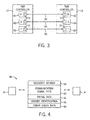
- the controllers 14 may be triple modular redundancy (TMR) controllers 14 as depicted in FIG. 3 .
- TMR controllers 14 may improve reliability by utilizing three cores. More specifically, as depicted, TMR controllers 14 include an R core 46, an S core 48, and a T core 50 that each functions substantially the same. Thus, the TMR controllers 14 operate through a voting scheme to reduce the effect of a malfunctioning core (e.g., 46, 48, or 50).
- each of the transmission systems may function similar to the data transmission system 10 described above, for example, by including data transmission subsystem 15 and operating substantially independent from one another.
- each transmission system e.g., 52, 54, and 56
- the first transmission system 52 may transmit parallel communication signals (e.g., two or more identical data transmissions) between the R cores 46
- the second transmission system 54 may transmit parallel communication signals between the S cores 48
- the third transmission system 56 may transmit parallel communication signals between the T cores 50.
- the first and second serial links may be included in a single or two separate conduits. Accordingly, in the embodiment depicted in FIG. 3 , three separate conduits or six separate conduits may be utilized. Alternatively, all six of the serial links may be included in a single conduit.
- the communication signal 58 includes a communication signal data 60, a sequence number 62, a timing data 64, a sender identification 66, and error check data 68.
- the communication signal data 60 may include the data intended to be communicated between the controllers 14.
- the communication signal data 60 may include control commands, login data, authentication data, voting data, measurement data, device statuses, and the like.
- the sequence number 62 may represent the order the communication signal 58 was transmitted. In some embodiments, the sequence number 62 may be included in the header of the communication signal 58. Accordingly, the sequence number 58 may enable a receiving controller 14 to determine the order communication signals 58 were transmitted.
- the timing data 64 may be generated by the FRC 28 to enable time synchronization of the communication signal 58.
- the timing data 64 may be a unique character representative of the count in the FRC 28. Thus, if the FRC 28 in the transmitting and receiving controllers 14 are synchronized, the timing data 64 enables the receiving controller 14 to determine when the communication signal 58 was transmitted.
- the sender identification 66 may identify the transmitting controller 14.
- the sender identification may be a media access control (MAC) address, a proprietary unique module identification code, or other similar unique identifier.
- the proprietary unique module identification code may include a unique serial number containing a date code. Accordingly, the sender identification 66 may enable the receiving controller 14 to determine the identity of the transmitting controller 14.
- the error check data 68 may include data that facilitates error check techniques, such as a cyclic redundancy check, a checksum, a cryptographic hash function, or the like.
- the error check data 68 may include a remainder of a polynomial division of the communication signal 58.
- the transmitting controller 14 may perform the error check technique and encode the error check data 68 (e.g., checksum) on the communication signal 58.
- the receiving controller 14 may detect errors/faults by repeating the error check technique and matching the result with the error check data 68 (e.g., calculating the checksum anew and verifying the calculation with the transmitted checksum).
- FIG. 5 depicts one embodiment of a process 70 that may be utilized by a transmitting controller 14, and more specifically the data transmission subsystem 15 (e.g., programmable logic device), to transmit parallel communication signals.
- the process 70 may be implemented by non-transitory machine-readable instructions or code stored in the memory 26 and executed by the processor 24.
- the process 70 begins by generating the first communication signal (bracket 72), which includes generating the communication signal data (process block 74), encoding a sequence number (process block 76), encoding timing data (process block 78), encoding a sender identification (process block 80), and encoding error data (process block 82).
- the process 70 continues by generating the second communication signal (process block 84), and transmitting the first communication signal on the first serial link (process block 86) and the second communication signal on the second serial link (process block 88) in parallel.
- the first communication signal may be generated by the data I/O 30.
- the data I/O 30 may gather the data to be transmitted on the first communication signal. For example, when a device status is to be transmitted, the data I/O 30 may poll a connected device (e.g., 16, 20 or 22) for its status or retrieve measurements from sensors (e.g., 18) that monitor the device.
- the data I/O 30 may include a sequential counter that increments with each communication signal transmitted. Thus, the count from the counter may be included as the sequence number 62 to represent the order a communication signal 58 is transmitted.
- the data I/O 30 may retrieve a stored unique identifier identifying the transmitting controller from the transmitting controller's memory 26.
- the data I/O 30 may receive the timing data 64 from the FRC 28. More specifically, the FRC 28 may generate the timing data 64 based on a timing signal received from the system clock 27. For example, the FRC 28 may count up based on the timing signal and reset the count once it reaches a particular count. Based on the count when the communication signal 58 is to be transmitted, the FRC 28 may output a unique character that represents the count. Thus, when a communication signal 58 is received, the receiving controller may compare the unique character to the count in its own FRC 28 to determine when the communication signal 58 was transmitted.
- the data I/O 30 may perform a data checking method, such as a cyclic redundancy check, a checksum, a cryptographic hash function, or the like. For example, when a cyclic redundancy check is utilized, the data I/O 30 may perform a polynomial division on the communication signal 58, or more specifically the communication signal data 60, and encode the remainder of the division as the error check data 68. Thus, the receiving controller 14 may detect errors by repeating the error check technique and matching the result with the error check data 68.
- a data checking method such as a cyclic redundancy check, a checksum, a cryptographic hash function, or the like.
- the data I/O 30 may perform a polynomial division on the communication signal 58, or more specifically the communication signal data 60, and encode the remainder of the division as the error check data 68.
- the receiving controller 14 may detect errors by repeating the error check technique and matching the result with the error check data 68.
- encoding the sequence number 62 (process block 76), encoding the timing data 64 (process block 76), encoding the sender identification 66 (process block 76), and encoding the error check data 68 (process block 76) may be performed in any order.
- the first communication signal may then be passed from the data I/O 30 to the data comparison/replication 32 to generate the second communication signal (process block 84). More specifically, the data comparison/replication 32 may generate the second communication signal to represent the same information as the first communication signal, for example, by copying the first communication signal. Additionally or alternatively, to generate the second communication signal, the data comparison/replication 32 may invert the first communication signal (e.g., change a "1" to a "0" and vice versa) or reverse the first communication signal (e.g., put most significant bit of the first communication signal as the least significant bit of the second communication signal and so on). For example, if the first communication signal is "10011100" a reversed second communication signal may be "00111001" and an inverted second signal may be "01100011."
- Reversing and/or inverting the first communication signal may facilitate detecting faults in the serial links and/or detecting/correcting errors in the data transmitted. For example, when the communication signals are inverted, an error in one of the communication signals may be detected if a bit in the first and second communication signals are both "high” or both "low.” Additionally, when the second communication signal is reversed, an error may be detected if the most significant bit of the first communication signal does not match the least significant bit of the second communication signal. Furthermore, the error may be corrected by replacing an erroneous bit on the first communication signal with a non-erroneous bit from the second communication signal.
- the first communication signal may be passed from the data comparison/replication 32 to the first I/O port 34 to be transmitted via the first serial link (process block 86), and the second communication signal may be passed from the data comparison/replication 32 to the second I/O port 36 via the second serial link (process block 88).
- the first communication signal and the second communication signal may be transmitted in parallel and substantially simultaneously.
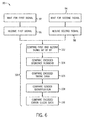
- FIG. 6 depicts an embodiment of a process 90 that may be utilized by the receiving controller 14, and more specifically the data transmission subsystem 15 (e.g., programmable logic device), to receive parallel communication signals 58, for example on a single conduit (e.g., Cat 5 cable).
- the process 90 may be implemented by non-transitory machine-readable instructions or code stored in the memory 26 and executed by the processor 24. As depicted, the process 90 begins by waiting for a first communication signal (process block 92) and waiting for a second communication signal (process block 94).
- the first and second communication signals are compared (bracket 100), which may include comparing the first and second communication signals for bit by bit agreement (process block 102), comparing the encoded sequence numbers (process block 104), comparing the encoded timing data (process block 106), comparing the sender identification (process block 108), and comparing the encoded error check data (process block 110).
- the data comparison/replication 32 may wait to receive the first communication signal via the first I/O port 34 (process block 92), and to receive the second communication signal via the second I/O port 36 (process block 94). In some embodiments, this may include employing a watchdog timeout for regularly scheduled communication signals 58. In other words, the data comparison/replication 32 may wait a predetermined amount of time, such an expected arrival time for a scheduled communication signal 58, and if the communication signal 58 is not received within that amount of time, the data comparison/replication signal 58 may output a timeout signal.
- the expected arrival time may be predetermined by the receiving controller 14 because utilizing a point-to-point architecture, as described above, may enable the controller 14 to look at the actual arrival time of previous communication signals 58.
- the data comparison/replication 32 is coupled to the clock system 27 to receive a timing signal.
- a communication signal 58 is expected every 1-5 milliseconds, 5-8 milliseconds, 8-10 milliseconds, 10-12 milliseconds, 12-15 milliseconds, 15-30 milliseconds, or any combination thereof. Accordingly, the output of a timeout signal may indicate that a communication signal 58 has been deleted or delayed.
- the data comparison/replication 32 may begin to compare the first and second communication signals (bracket 100), which may facilitate the detection of faults in the serial links and detection/correction of errors in the transmitted data. More specifically, to compare the first communication signal and the second communication signal for bit by bit agreement (process block 102), the data comparison/replication 32 may invert or reverse the second communication signal before comparing it with the first communication signal because, as described above, the second communication signal may be a reversed or inverted version of the first communication signal. Accordingly, the bit by bit comparison may indicate that a bit in the communication signal 58 has been deleted, inserted, or corrupted. Additionally, as will be described in more detail below, the bit by bit comparison may facilitate real-time correction of a bit in the communication signal 58.
- the data comparison/replication 32 may retrieve the sequence number 62 from the header of the communication signal 58, which enables the controller 14 to determine the order the communication signal 58 was transmitted. More specifically, the data comparison/replication 32 may compare the sequence number 62 encoded on one or both of the first and second communication signals to an expected sequence number 62. For example, a repetition error may be detected if the sequence numbers 62 encoded on the communication signals 58 are the same as a previous pair of communication signals. Additionally, a deletion, insertion or resequence error may be detected if the sequence numbers 62 encoded on the communication signals 58 are different from the expected sequence number.
- utilizing a point-to-point serial architecture may enable the receiving controller 14 to maintain the expected sequence number because, if there are no errors, the sequence number 62 encoded on each communication signal 58 received will have a predetermine relationship with the sequence number 62 encoded on a previously received communication signal 58. Accordingly, comparing the sequence number 62 may indicate that one or both of the communication signals 58 is repeated, deleted, inserted, or resequenced.
- the data comparison/replication 32 may time synchronize one or both of the first communication signal and the second communication signal. In some embodiments, this may include determining the time the communication signals 58 were transmitted by matching the timing data 64 encoded on the communication signals 58 with the stored timing data 64 in memory 26 generated by the FRC 28 on the receiving controller 14. For example, the FRC 28 on both the transmitting and receiving controller may generate a unique character "X" to indicate 3:00 pm. Additionally, a repetition error may be detected if the timing data 64 encoded on the communication signals 58 is the same as the timing data 64 encoded on a previously received communication signal 58.
- a resequence or delay error may be detected if the timing data encoded on the communication signals 58 is earlier than the timing data 64 encoded on a previously received communication signal 58.
- comparing the encoded timing data 64 may indicate that one or both of the communication signals 58 is repeated, resequenced, or delayed.
- the data comparison/replication 32 may determine the identity of the transmitting controller 14. More specifically, this may include matching the sender identification 66 encoded on one or both of the first communication signal and the second communication signal with a sender identification 66 stored in memory 26.
- the controller memory 26 may store a list of sender identifications 66 that correspond to devices that the controller expects to receive communication signals 58 from.
- utilizing a point-to-point serial architecture, as described above may enable the receiving controller 14 to predetermine what devices the controller 14 is coupled to and store the sender identifications associated with those devices. Accordingly, comparing the encoded sender identification 66 may indicate that one or both of the communication signals 58 is inserted if the encoded sender identification 66 corresponds to a device that the controller 14 does not expect to receive communication signals 58 from.
- the data comparison/replication 32 may perform an error check technique, such as a cyclic redundancy check (CRC), on one or both of the first communication signal and the second communication to determine whether the received communication signals 58 are corrupted. More specifically, the data comparison/replication 32 may replicate the error check technique performed in the transmitting controller 14 and compare its results with the encoded error check data 68. Accordingly, comparing the encoded error check data 68 may indicate that one or both of the communication signals 58 is corrupted or otherwise do not match each other.
- CRC cyclic redundancy check
- comparing the communication signals bit by bit may be performed in any order.
- detection of an insertion, deletion, delay, or any combination thereof may indicate a masquerade.
- a masquerade is intended to describe an unauthenticated intrusion into the transmission system 10. For example, when a communication signal 58 is inserted, deleted, or delayed, this may indicate that an unauthorized device (e.g., controller 14) is accessing the transmission system 10 and altering the communication signals 58.
- FIG. 7 One embodiment of a process 112 that may be utilized to detect faults in the serial links is depicted in FIG. 7 .
- the process 112 may be implemented by non-transitory machine-readable instructions or code stored in the memory 26 and executed by the processor 24. As depicted, the process 112 may begin by waiting for the first and second communication signal (decision block 114). If both communication signals are received, the first and second communication signals may be compared (process block 100).
- a fault in the serial link may be detected (decision block 116). If no fault in the serial link is detected, the transmission system 10 continues operation (process block 118). On the other hand, if a fault is detected, it may be determined (decision block 120) whether the transmission system 10 should continue operation despite the detected fault (process block 118) or cease operation (process block 122).
- the data comparison/replication 32 may wait a specified amount of time, such as a communication signal frame, for the communication signals 58 (process block 114). If one or both of the communication signals 58 is not received, the data comparison/replication 32 may output a timeout signal indicating that one or both of the communication signals 58 has timed out.
- a specified amount of time such as a communication signal frame
- the data comparison/replication 32 may compare the communication signals 58 (process block 100), which may include comparing the first and second communication signals 58 for bit by bit agreement (process block 102), comparing the encoded sequence numbers (process block 104), comparing the encoded timing data (process block 106), comparing the sender identification (process block 108), and comparing the encoded error check data (process block 110).
- comparing the communications signals may facilitate the detection of errors in data transmitted in the communication signals.
- the data comparison/replication 32 may determine whether a fault is present in the first serial link, the second serial link, or both (decision block 116). For example, if the first communication signal has timed out, but the second communication signal has not, the data comparison/replication 32 may determine that the first serial link has a fault. Additionally, any error (e.g., repetition, deletion, insertion, resequence, corruption, delay, or masquerade) may indicate a fault in one or more of the serial links. For example, corruption of the first communication signal 58 but not the second communication signal 58 may indicate that the insulation on the first serial link is weakened and susceptible to external interference, such as stray electromagnetic waves.
- any error e.g., repetition, deletion, insertion, resequence, corruption, delay, or masquerade
- the status of the serial link may be updated based on the fault. For example, before a fault is detected, the status of the first serial link and the second serial link is set to "good,” but when a fault in the first serial link is detected, the status of the first serial link may be updated to "faulty.” As will be described further below, in other embodiments, the status may include intermediate statuses to enable the transmission system 10 to more judiciously manage operation.
- a serial link may have a status of "partially faulty" or “potentially faulty” if only a single error is detected or if an error is only detected periodically (e.g., not in every communication signal transmitted). For example, when a first error is detected, the status may be updated from “functional" to "potentially faulty," and when a second error is detected three communication signals later, the status may again be updated to "faulty.”
- the data comparison/replication 32 may more judiciously determine whether to cease or continue operation of the transmission system based on the circumstances associated with the fault (decision block 120). In other words, the transmission system 10 may become more fault tolerant and not immediately shut down each time a fault in the serial links is detected. In some embodiments, the decision whether to continue operation may depend on the status of the serial links and the information included in the communication signal 58. For example, if the first serial link is "functional" but the second serial link is "faulty" and the communication signal 58 merely communicates a temperature measurement, the transmission system 10 may continue operations solely based on the communication signals 58 received via the first serial link. In such an embodiment, the controller 14 may decide to continue transmitting and receiving sensor 18 measurements but may decide to cease transmission/reception of control commands.
- a transmission system 10 in a candy manufacturing plant may be more fault tolerant than a nuclear plant and choose to operate with one "functional" serial link and one "potentially faulty" link, whereas the nuclear play may to operate only with two "functional" serial links.
- the transmission system 10 may attribute the error to an anomaly and continue operation until a subsequent error is detected. In such embodiments, the transmission system 10 may decide to continue operation for a set period to give an operator an opportunity to correct the faulty serial link, but cease operation if the fault has not been correct after the set period.
- the decision whether to continue operation may depend on whether the error is correctable in real-time. For example, if the error is a deletion or a corruption of the most significant bit on both communication signals 58 and the communication signals are reversed, the transmission system 10 may choose to continue operation based on the corrected communication signals 58.
- the correctability of errors in communication signals 58 will be described in more detail below.
- the decision whether to continue or cease operation may be customized based on one or more of a variety of factors, such as the nature of the system utilizing the transmissions system 10, the status the serial links, whether an error in the communication signals 58 is correctable in real-time, the nature of the information transmitted in the communication signals 58, the history of errors, and the like. Functions utilized for such determinations may be performed by the data comparison/replication 32 or other systems of the processor 24 and/or memory 26.
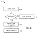
- FIG. 8 One embodiment of a process 124 for correcting an error in real time is depicted in FIG. 8 .
- the process 124 may be implemented by non-transitory machine-readable instructions or code stored in the memory 26 and executed by the processor 24.
- a determination is made whether the error is correctable (decision block 128). If the error is uncorrectable, the transmission system 10 may cease operation (process block 132). If it is correctable, the error is corrected in real-time (process block 134) and the transmission system 10 continues operation (process block 136).
- the data comparison/replication 32 may determine whether the error is correctable based on various factors, such as the type of error and the magnitude of the error. For example, in the example described above, if the error is merely corrupting the most significant bit of each communication signal 58 and the communication signals 58 are reversed, the data comparison/replication 32 may correct the error by replacing the most significant bit on the first communication signal with the least significant bit on the second communication signal and vice versa. Additionally, if the error detected is a repetition, the transmission system 10 may correct the error simply by executing the earlier receive communication signals and disregarding the subsequently received. Similarly, if the error detected is an insertion, the transmission system may correct the error simply be disregarding the inserted communication signals 58. On the other hand, if the error detected is a masquerade, the error may not be correctable and the transmission system 10 may choose to cease operation because an intrusion into the transmission system 10 has been detected.
- the data comparison/replication 32 may correct errors affecting one or more bits of the first communication signal in real-time by replacing erroneous bits in the first communication signal with non-erroneous bits from the second communication signal. Additionally, the data comparison/replication 32 may correct errors affecting the first communication signal but not the second communication signal by disregarding the first communication signal. Furthermore, the data comparison/replication 32 may correct errors affecting both the first and second communication signal by disregarding both. It should be appreciated that the correctability of a detected error may be fact specific. Functions utilized for such determinations may be performed by the data comparison/replication 32 or other parts of the processor 24 and/or memory 26.
- the techniques described herein enable the errors to be corrected in real-time or as soon as the error is detected.
- the most significant bit of the first communication signal may be replaced with the least significant bit of the second communication signal when they are compared bit by bit, the earlier received communication signal 58 may be executed upon receipt and the subsequently received communication signals may be disregarded upon receipt, and the inserted communication signal 58 may be disregarded upon receipt.
- the reliability of the data transmission system 10 may be improved by utilizing parallel serial links that each transmits a communication signal 58 representative of the same information in parallel. Based on receipt and comparison of the parallel communication signals 58, faults in the serial links and errors in the communication signals may be detected. Accordingly, the reliability of the transmission system 10 may be improved by making the transmission system 10 more fault tolerant and correcting errors in real time. Additionally, in some embodiments, the detection and/or correction of faults and errors may be provided only with the use of hardware, which enables the improved reliability to be provided to all devices regardless of processing capabilities.
Landscapes
- Engineering & Computer Science (AREA)
- Computer Networks & Wireless Communication (AREA)
- Signal Processing (AREA)
- Quality & Reliability (AREA)
- Physics & Mathematics (AREA)
- Probability & Statistics with Applications (AREA)
- Theoretical Computer Science (AREA)
- Detection And Prevention Of Errors In Transmission (AREA)
Applications Claiming Priority (1)
| Application Number | Priority Date | Filing Date | Title |
|---|---|---|---|
| US14/145,636 US9374194B2 (en) | 2013-12-31 | 2013-12-31 | Transmission system error detection and correction system and method |
Publications (1)
| Publication Number | Publication Date |
|---|---|
| EP2890037A1 true EP2890037A1 (fr) | 2015-07-01 |
Family
ID=52272890
Family Applications (1)
| Application Number | Title | Priority Date | Filing Date |
|---|---|---|---|
| EP14199463.2A Pending EP2890037A1 (fr) | 2013-12-31 | 2014-12-19 | Système de transmission, système de détection et de correction d'erreur et procédé |
Country Status (5)
| Country | Link |
|---|---|
| US (1) | US9374194B2 (fr) |
| EP (1) | EP2890037A1 (fr) |
| JP (1) | JP6635653B2 (fr) |
| CN (1) | CN104753716B (fr) |
| AU (1) | AU2014274577B2 (fr) |
Families Citing this family (11)
| Publication number | Priority date | Publication date | Assignee | Title |
|---|---|---|---|---|
| FR3024932B1 (fr) * | 2014-08-14 | 2017-12-01 | Sagem Defense Securite | Procede de transmission de donnees a robustesse amelioree et ensemble de dispositifs pour sa mise en œuvre |
| CN105120364A (zh) * | 2015-08-24 | 2015-12-02 | 天脉聚源(北京)科技有限公司 | 一种用于电视互动系统安全传输互动信号的方法 |
| JP6696252B2 (ja) * | 2016-03-24 | 2020-05-20 | 富士ゼロックス株式会社 | 通信プログラム、通信装置及び情報処理装置 |
| US11044260B2 (en) * | 2016-04-01 | 2021-06-22 | The Regents Of The University Of Michigan | Fingerprinting electronic control units for vehicle intrusion detection |
| US10025677B2 (en) * | 2016-12-05 | 2018-07-17 | Arteris, Inc. | Redundancy for cache coherence systems |
| CN109245870B (zh) * | 2017-06-16 | 2021-12-28 | 华为技术有限公司 | 处理无线链路失败方法、终端设备和基站 |
| US10802932B2 (en) * | 2017-12-04 | 2020-10-13 | Nxp Usa, Inc. | Data processing system having lockstep operation |
| US11109188B2 (en) * | 2018-04-18 | 2021-08-31 | Disney Enterprises, Inc. | Real-time processing of spatiotemporal data |
| CN111177793B (zh) * | 2018-11-13 | 2022-05-20 | 中车株洲电力机车研究所有限公司 | 数字量采集及通信传输系统 |
| US20200210544A1 (en) * | 2018-12-29 | 2020-07-02 | Arteris, Inc. | System and method for reducing silicon area of resilient systems using functional and duplicate logic |
| CN113741471B (zh) * | 2021-09-10 | 2023-08-25 | 南京苏美达智能技术有限公司 | 一种自动行走设备、基站及其数据交互方法 |
Citations (2)
| Publication number | Priority date | Publication date | Assignee | Title |
|---|---|---|---|---|
| EP1091518A2 (fr) * | 1999-10-06 | 2001-04-11 | Advantest Corporation | Système et procédé pour la mesure d'erreurs de bits |
| US20130318406A1 (en) * | 2011-04-22 | 2013-11-28 | Mitsubishi Electric Corporation | Communication device using plurality of communication paths |
Family Cites Families (18)
| Publication number | Priority date | Publication date | Assignee | Title |
|---|---|---|---|---|
| JPS5742244A (en) * | 1980-08-28 | 1982-03-09 | Fujitsu Ltd | Optical transmission system |
| US4633473A (en) * | 1984-08-02 | 1986-12-30 | United Technologies Corporation | Fault tolerant communications interface |
| JPS6331241A (ja) * | 1986-07-25 | 1988-02-09 | Nec Corp | スイツチ信号転送方式 |
| US6397157B1 (en) | 1999-07-02 | 2002-05-28 | General Electric Company | Method and apparatus for real time measurement of three phase electrical parameters |
| US6879922B2 (en) | 2001-09-19 | 2005-04-12 | General Electric Company | Systems and methods for suppressing pressure waves using corrective signal |
| JP4209743B2 (ja) * | 2003-08-08 | 2009-01-14 | 三菱電機株式会社 | 電子制御装置 |
| JP4468795B2 (ja) * | 2004-12-02 | 2010-05-26 | 株式会社 エニイワイヤ | 制御・監視信号伝送システム、電子装置 |
| JP4498973B2 (ja) * | 2005-05-11 | 2010-07-07 | 株式会社日立製作所 | 無線通信装置、無線通信装置の制御方法、およびプログラム |
| US7343744B2 (en) | 2005-07-27 | 2008-03-18 | General Electric Company | Method and system for controlling a reheat turbine-generator |
| US7642748B2 (en) | 2005-10-19 | 2010-01-05 | General Electric Company | Battery charging system and method of operating same |
| US7870299B1 (en) * | 2008-02-06 | 2011-01-11 | Westinghouse Electric Co Llc | Advanced logic system |
| US8117512B2 (en) * | 2008-02-06 | 2012-02-14 | Westinghouse Electric Company Llc | Failure detection and mitigation in logic circuits |
| DE102009033241B4 (de) * | 2009-07-14 | 2013-07-04 | Audi Ag | Vermeidung von Maskerade durch Verwendung von Kennungssequenzen |
| JP5548461B2 (ja) * | 2010-01-15 | 2014-07-16 | 株式会社リブ技術研究所 | 通信回路、通信ネットワークおよび連結装置 |
| JP5394283B2 (ja) * | 2010-02-25 | 2014-01-22 | 株式会社日立産機システム | 情報処理装置及び制御用ネットワークシステム |
| JP5167329B2 (ja) * | 2010-11-29 | 2013-03-21 | 株式会社日立製作所 | 車両制御用無線通信システム |
| JP5621554B2 (ja) * | 2010-11-30 | 2014-11-12 | 日本電気株式会社 | エラー訂正回路及びエラー訂正方法 |
| JP5804365B2 (ja) * | 2011-08-24 | 2015-11-04 | 国立大学法人 大分大学 | ダイバーシティ光伝送装置および方法 |
-
2013
- 2013-12-31 US US14/145,636 patent/US9374194B2/en active Active
-
2014
- 2014-12-11 AU AU2014274577A patent/AU2014274577B2/en active Active
- 2014-12-19 EP EP14199463.2A patent/EP2890037A1/fr active Pending
- 2014-12-25 JP JP2014261431A patent/JP6635653B2/ja active Active
- 2014-12-31 CN CN201410852488.0A patent/CN104753716B/zh active Active
Patent Citations (2)
| Publication number | Priority date | Publication date | Assignee | Title |
|---|---|---|---|---|
| EP1091518A2 (fr) * | 1999-10-06 | 2001-04-11 | Advantest Corporation | Système et procédé pour la mesure d'erreurs de bits |
| US20130318406A1 (en) * | 2011-04-22 | 2013-11-28 | Mitsubishi Electric Corporation | Communication device using plurality of communication paths |
Non-Patent Citations (1)
| Title |
|---|
| NATH M: "CAN PROTOCOL EASES AUTOMOTIVE-ELECTRONICS NETWORKING", EDN ELECTRICAL DESIGN NEWS.(TEXAS INSTRUMENT), REED BUSINESS INFORMATION, HIGHLANDS RANCH, CO, US, vol. 43, no. 17, 17 August 1998 (1998-08-17), XP000848375, ISSN: 0012-7515 * |
Also Published As
| Publication number | Publication date |
|---|---|
| JP6635653B2 (ja) | 2020-01-29 |
| AU2014274577B2 (en) | 2019-07-18 |
| CN104753716A (zh) | 2015-07-01 |
| US9374194B2 (en) | 2016-06-21 |
| CN104753716B (zh) | 2019-11-12 |
| AU2014274577A1 (en) | 2015-07-16 |
| JP2015130668A (ja) | 2015-07-16 |
| US20150188664A1 (en) | 2015-07-02 |
Similar Documents
| Publication | Publication Date | Title |
|---|---|---|
| US9374194B2 (en) | Transmission system error detection and correction system and method | |
| US9178757B2 (en) | Serial link fault detection system and method | |
| EP2490124B1 (fr) | Contrôleur de processus doublement redondant | |
| CN101111822B (zh) | 信息处理设备和信息处理方法 | |
| CN110851392B (zh) | 基于Modbus RTU协议的通讯方法及通讯系统 | |
| US8966340B2 (en) | System and method for fault tolerant computing using generic hardware | |
| US11016463B2 (en) | Control and data-transfer system, gateway module, I/O module, and method for process control | |
| US8543370B2 (en) | Multiple PLC simulation system | |
| CN104516306B (zh) | 冗余的自动化系统 | |
| EP3979527A1 (fr) | Système et procédé d'heure synchronisée sur le réseau dans les applications de sécurité | |
| KR101560497B1 (ko) | 락스텝으로 이중화된 프로세서 코어들의 리셋 제어 방법 및 이를 이용하는 락스텝 시스템 | |
| US20100050062A1 (en) | Sending device, receiving device, communication control device, communication system, and communication control method | |
| US20200096962A1 (en) | Field Device and Method for Parameterizing the Field Device | |
| US8554966B2 (en) | Method for data exchange | |
| US9641287B2 (en) | Methods and apparatus for high-integrity data transfer with preemptive blocking | |
| EP3507944B1 (fr) | Vote amélioré pour redondance de ligne profibus | |
| JP2006033075A (ja) | シリアル通信装置 | |
| Saha et al. | Analysis of residual errors and their consequences in CANopen systems |
Legal Events
| Date | Code | Title | Description |
|---|---|---|---|
| PUAI | Public reference made under article 153(3) epc to a published international application that has entered the european phase |
Free format text: ORIGINAL CODE: 0009012 |
|
| 17P | Request for examination filed |
Effective date: 20141219 |
|
| AK | Designated contracting states |
Kind code of ref document: A1 Designated state(s): AL AT BE BG CH CY CZ DE DK EE ES FI FR GB GR HR HU IE IS IT LI LT LU LV MC MK MT NL NO PL PT RO RS SE SI SK SM TR |
|
| AX | Request for extension of the european patent |
Extension state: BA ME |
|
| R17P | Request for examination filed (corrected) |
Effective date: 20160104 |
|
| RBV | Designated contracting states (corrected) |
Designated state(s): AL AT BE BG CH CY CZ DE DK EE ES FI FR GB GR HR HU IE IS IT LI LT LU LV MC MK MT NL NO PL PT RO RS SE SI SK SM TR |
|
| STAA | Information on the status of an ep patent application or granted ep patent |
Free format text: STATUS: EXAMINATION IS IN PROGRESS |
|
| 17Q | First examination report despatched |
Effective date: 20180912 |
|
| STAA | Information on the status of an ep patent application or granted ep patent |
Free format text: STATUS: EXAMINATION IS IN PROGRESS |
|
| STAA | Information on the status of an ep patent application or granted ep patent |
Free format text: STATUS: EXAMINATION IS IN PROGRESS |
|
| RAP1 | Party data changed (applicant data changed or rights of an application transferred) |
Owner name: GENERAL ELECTRIC TECHNOLOGY GMBH |