EP2889973A1 - Élément extérieur de faisceau électrique et faisceau électrique - Google Patents
Élément extérieur de faisceau électrique et faisceau électrique Download PDFInfo
- Publication number
- EP2889973A1 EP2889973A1 EP13830678.2A EP13830678A EP2889973A1 EP 2889973 A1 EP2889973 A1 EP 2889973A1 EP 13830678 A EP13830678 A EP 13830678A EP 2889973 A1 EP2889973 A1 EP 2889973A1
- Authority
- EP
- European Patent Office
- Prior art keywords
- wire harness
- tube body
- exterior member
- rigidity
- rigidity adding
- Prior art date
- Legal status (The legal status is an assumption and is not a legal conclusion. Google has not performed a legal analysis and makes no representation as to the accuracy of the status listed.)
- Granted
Links
- 239000002131 composite material Substances 0.000 description 16
- 239000012212 insulator Substances 0.000 description 8
- 238000001125 extrusion Methods 0.000 description 5
- 230000005855 radiation Effects 0.000 description 5
- 239000011347 resin Substances 0.000 description 5
- 229920005989 resin Polymers 0.000 description 5
- 238000004519 manufacturing process Methods 0.000 description 4
- 239000002184 metal Substances 0.000 description 2
- 238000000034 method Methods 0.000 description 2
- 239000000203 mixture Substances 0.000 description 2
- 238000000465 moulding Methods 0.000 description 2
- 229910018095 Ni-MH Inorganic materials 0.000 description 1
- 229910018477 Ni—MH Inorganic materials 0.000 description 1
- 238000005452 bending Methods 0.000 description 1
- 239000003990 capacitor Substances 0.000 description 1
- 239000004020 conductor Substances 0.000 description 1
- 238000001816 cooling Methods 0.000 description 1
- 230000000694 effects Effects 0.000 description 1
- 230000001771 impaired effect Effects 0.000 description 1
- 229910001416 lithium ion Inorganic materials 0.000 description 1
- 239000000463 material Substances 0.000 description 1
- 230000000191 radiation effect Effects 0.000 description 1
- 230000002787 reinforcement Effects 0.000 description 1
- XLYOFNOQVPJJNP-UHFFFAOYSA-N water Substances O XLYOFNOQVPJJNP-UHFFFAOYSA-N 0.000 description 1
- 238000004078 waterproofing Methods 0.000 description 1
Images


Classifications
-
- H—ELECTRICITY
- H02—GENERATION; CONVERSION OR DISTRIBUTION OF ELECTRIC POWER
- H02G—INSTALLATION OF ELECTRIC CABLES OR LINES, OR OF COMBINED OPTICAL AND ELECTRIC CABLES OR LINES
- H02G3/00—Installations of electric cables or lines or protective tubing therefor in or on buildings, equivalent structures or vehicles
- H02G3/02—Details
- H02G3/04—Protective tubing or conduits, e.g. cable ladders or cable troughs
- H02G3/0406—Details thereof
-
- B—PERFORMING OPERATIONS; TRANSPORTING
- B60—VEHICLES IN GENERAL
- B60R—VEHICLES, VEHICLE FITTINGS, OR VEHICLE PARTS, NOT OTHERWISE PROVIDED FOR
- B60R16/00—Electric or fluid circuits specially adapted for vehicles and not otherwise provided for; Arrangement of elements of electric or fluid circuits specially adapted for vehicles and not otherwise provided for
- B60R16/02—Electric or fluid circuits specially adapted for vehicles and not otherwise provided for; Arrangement of elements of electric or fluid circuits specially adapted for vehicles and not otherwise provided for electric constitutive elements
- B60R16/0207—Wire harnesses
- B60R16/0215—Protecting, fastening and routing means therefor
-
- F—MECHANICAL ENGINEERING; LIGHTING; HEATING; WEAPONS; BLASTING
- F16—ENGINEERING ELEMENTS AND UNITS; GENERAL MEASURES FOR PRODUCING AND MAINTAINING EFFECTIVE FUNCTIONING OF MACHINES OR INSTALLATIONS; THERMAL INSULATION IN GENERAL
- F16L—PIPES; JOINTS OR FITTINGS FOR PIPES; SUPPORTS FOR PIPES, CABLES OR PROTECTIVE TUBING; MEANS FOR THERMAL INSULATION IN GENERAL
- F16L57/00—Protection of pipes or objects of similar shape against external or internal damage or wear
-
- H—ELECTRICITY
- H02—GENERATION; CONVERSION OR DISTRIBUTION OF ELECTRIC POWER
- H02G—INSTALLATION OF ELECTRIC CABLES OR LINES, OR OF COMBINED OPTICAL AND ELECTRIC CABLES OR LINES
- H02G3/00—Installations of electric cables or lines or protective tubing therefor in or on buildings, equivalent structures or vehicles
- H02G3/02—Details
- H02G3/04—Protective tubing or conduits, e.g. cable ladders or cable troughs
- H02G3/0462—Tubings, i.e. having a closed section
- H02G3/0481—Tubings, i.e. having a closed section with a circular cross-section
-
- H—ELECTRICITY
- H02—GENERATION; CONVERSION OR DISTRIBUTION OF ELECTRIC POWER
- H02G—INSTALLATION OF ELECTRIC CABLES OR LINES, OR OF COMBINED OPTICAL AND ELECTRIC CABLES OR LINES
- H02G3/00—Installations of electric cables or lines or protective tubing therefor in or on buildings, equivalent structures or vehicles
- H02G3/02—Details
- H02G3/04—Protective tubing or conduits, e.g. cable ladders or cable troughs
- H02G3/0462—Tubings, i.e. having a closed section
- H02G3/0487—Tubings, i.e. having a closed section with a non-circular cross-section
Definitions
- the present invention relates to a wire harness exterior member and a wire harness including this exterior member.
- High-voltage (i.e., for high voltage) wire harnesses are used as components for electrical connection between a battery and an inverter unit of a hybrid car or an electric car.
- Some wire harnesses for the electrical connection between the battery and the inverter unit include a plurality of high-voltage conducting paths and an exterior member for protecting these conducting paths (see Patent Document 1 identified below).
- Patent Document 1 JP 2004-171952 A
- the present invention has been made in view of the above circumstances, and it is an object thereof provide a wire harness exterior member and a wire harness that enable thickness reduction.
- the wire harness exterior member and the wire harness according to the present invention have the following features (1) to (9):
- the straight tube body can be reduced in thickness, so that the weight and cost can be reduced.
- the rigidity can be secured by the rigidity adding portion, even if the straight tube body is reduced in thickness, the straight tube body can be prevented from being deformed.
- the workability at the time of manufacture of the wire harness and the workability at the time of fixing of the wire harness to the vehicle body and the like can be improved.
- this rigidity adding portion can be used for improving the durability against external causes such as a curb.
- the rigidity adding portion is provided so as to protrude on the outer surface of the straight tube body or is formed such that the straight tube body is deformed inward. For this reason, according to the wire harness exterior member of (2) described above, the rigidity adding portion can be used not only as the portion that adds rigidity but also for securing anti-chipping performance and for improving heat radiation performance.
- the rigidity adding portion is provided so as to protrude on the inner surface of the straight tube body or is formed such that the straight tube body is deformed inward.
- the rigidity adding portion can be used not only for adding rigidity but also for improving heat radiation performance.
- the rigidity adding portion since the rigidity adding portion does not protrude outward, attachment of post-fitting parts is facilitated, and at the time of fixing of the wire harness to the vehicle body, work is not obstructed.
- the rigidity adding portion is formed in the configuration extending in the axial direction of the straight tube body, a wire harness exterior member that can be formed by extrusion molding can be provided.
- a wire harness exterior member having the straight tube portion and the flexible tube portion can be provided.
- the rigidity adding portion is provided at the vertically lower portion of the outer surface of the straight tube body in the state of being fixed to the vehicle underfloor portion. Therefore, the rigidity adding portion can be used not only for adding rigidity but also for securing anti-chipping performance and for improving the durability against external causes such as a curb.
- the rigidity adding portion is provided at the vertically lower side of the outer surface of the straight tube body and at the vertically upper side situated on the opposite side in the state of being fixed to the vehicle underfloor portion, the rigidity of the straight tube body can be enhanced.
- the straight tube body can be further reduced in thickness.
- a wire harness can be provided the weight and cost of which can be reduced and further, that is also excellent in anti-chipping performance, workability and the like.
- a wire harness according to the present embodiment includes a conducting path and a wire harness exterior member accommodating and protecting this wire harness.
- the wire harness exterior member is a tube body made of a resin or a metal, and has a rigidity adding portion for adding rigidity.
- Fig. 1 is a schematic view illustrating an arrangement of the wire harness according to the present invention.
- Fig. 2 is a structural view of the wire harness
- Fig. 3 is a perspective view of the exterior member
- Fig. 4(a) to Fig. 8(b) are perspective views of the rigidity adding portions as other examples.
- the wire harness including the wire harness exterior member of the embodiment is arranged to a hybrid car (this may be an electric car or a general car).
- reference designation 1 represents a hybrid car.
- the hybrid car 1 is a vehicle driven by a mixture of two powers of an engine 2 and a motor unit 3.
- the motor unit 3 is supplied with the power from a battery 5 (in other words, a battery pack) through an inverter unit 4.
- the engine 2, the motor unit 3 and the inverter unit 4 are, in this example, mounted in an engine room 6 in a position close to the front wheels and the like.
- the battery 5 is mounted in a vehicle rear portion 7 close to the rear wheels and the like.
- the battery 5 may be mounted in a car cabin that is present in the rear of the engine room 6.
- the motor unit 3 and the inverter unit 4 are electrically connected to each other via a high-voltage wire harness 8.
- the battery 5 and the inverter unit 4 are also electrically connected to each other via a high-voltage wire harness 9.
- the wire harness 9 has its intermediate portion 10 arranged on the ground side of a vehicle underfloor portion surface 11.
- the wire harness 9 is substantially parallelly arranged along the vehicle underfloor portion 11.
- the vehicle underfloor portion 11 is a known body and is also a so-called panel member, and a through hole (not shown) is formed in a predetermined position. Through this through hole, the wire harness 9 is inserted.
- the wire harness 9 and the battery 5 are electrically connected through a junction block 12 provided on this battery 5.
- a rear end portion 13 of the wire harness 9 is electrically connected by a known method.
- the side of a front end portion 14 of the wire harness 9 is electrically connected to the inverter unit 4 by a known method.
- the motor unit 3 has a motor (not shown) and a generator (not shown). Moreover, the inverter unit 4 has an inverter (not shown) and a converter (not shown).
- the motor unit 3 is formed as a motor assembly including a shielding case (not shown). Moreover, the inverter unit 4 is formed as an inverter assembly including a shielding case (not shown).
- the battery 5 which is an Ni-MH or Li-ion battery is modularized. For example, an electric storage device such as a capacitor may be used.
- the battery 5 is not specifically limited as long as it can be used for the hybrid car 1 and an electric car.
- the wire harness 9 is a high voltage member for electrically connecting the inverter unit 4 and the battery 5 as mentioned above, and is structured so as to include a high-voltage coaxial composite conducting path 15 (that is, the conducting path) and an exterior member 16 (that is, the wire harness exterior member).
- the wire harness 9 of this structure has its path arranged, for example, so as to be hidden beside a non-illustrated reinforcement on the vehicle underfloor portion 11.
- the high-voltage coaxial composite conducting path 15 has a positive circuit and a negative circuit in this single path. That is, the high-voltage coaxial composite conducting path 15 has two systems of circuits. Specifically, the high-voltage coaxial composite conducting path 15 has a first conducting path 17 that is circular in cross section and situated at the core of the high-voltage coaxial composite conducting path 15 and a first insulator 18 covering the periphery of this first conducting path 17 with a predetermined thickness. Moreover, the high-voltage coaxial composite conducting path 15 has a second conducting path 19 provided on the outside of the first insulator 18 and a second insulator 20 covering the periphery of this second conducting path 19 with a predetermined thickness. Further, the high-voltage coaxial composite conducting path 15 includes an electromagnetic shielding member 21 provided on the outside of the second insulator 20 and a sheath 22 covering the periphery of this electromagnetic shielding member 21 with a predetermined thickness.
- the conducting path may be, other than the high-voltage coaxial composite conducting path 15 described above, a known high-voltage electric wire including a conductor and an insulator, a shielded wire, a cabtire cable, a bus bar provided with an insulator.
- the number of the conducting paths may be one or more.
- the high-voltage coaxial composite conducting path 15 is of two systems in the present embodiment, the present invention is not limited thereto; it may be of three systems,... a number, n, of systems. Moreover, the high-voltage coaxial composite conducting path 15 may have a structure not having the sheath 22.
- the exterior member 16 is a tube body made of a resin for accommodating and protecting the high-voltage coaxial composite conducting path 15, and has a flexible tube portion 23 and an inflexible tube portion 24 (i.e., a straight tube portion).
- the flexible tube portion 23 becomes a bent portion during the shipping or the routing of the wire harness 9, and the inflexible tube portions 24 continues from the flexible tube portion 23.
- the inflexible tube portion 24 is provided as an inflexible portion.
- the exterior member 16 is, in the present embodiment, a resin molding product obtained by extrusion molding of a desired resin material.
- the exterior member 16 is not limited to a resin-made one but may be a metal-made one as long as it has a rigidity adding portion 28 described later.
- the flexible tube portion 23 and the inflexible tube portion 24 are each formed more than one in number in the present embodiment, they are formed at least one in number, and the number thereof is not specifically limited. That is, a structure may be adopted in which the number of flexible tube portions 23 is one and on each side thereof, one inflexible tube portion 24 is formed so as to be continuous therewith. Alternatively, a structure may be adopted in which the number of inflexible tube portions 24 is one and on each side thereof, one flexible tube portion 23 is formed so as to be continuous therewith.
- the flexible tube portion 23 is formed in the configuration of an accordion tube having a depression 25 and a protrusion 26 formed around the periphery thereof in the circumferential direction, more than one in number continuously in the direction of the length thereof.
- the flexible tube portion 23 has its length set according to the bending range.
- the flexible tube portion 23 has bendability (in other words, flexibility) and is formed at a part that can be bent.
- the flexible tube portion 23 is formed at a part similar to a known corrugated tube in the present embodiment.
- the flexible tube portion 23 is not limited to the above-mentioned accordion tube configuration as long as it is bendable.
- the flexible tube portion 23 has its cross-sectional shape formed so as to coincide with the cross-sectional shape of an inflexible tube body 27 described later (this is an example, and the cross-sectional shape may be a different one).
- the exterior member 16 has the part of a configuration similar to that of a corrugated tube as mentioned above, it can be regarded as a "corrugated tube", a “partially corrugated tube” or the like.
- the exterior member 16 is formed in a configuration where no slits are provided (that is, there are no incisions) in the direction of the tube axis thereof (that is, the direction of the length). As a reason that no slits are provided, the enhancement of rigidity and strength is cited. Moreover, improving waterproofing property by preventing water intrusion into the exterior member 16 is also cited. Further, making it difficult for the high-voltage coaxial composite conducting path 15 to be exposed, for example, from the bent part of the exterior member 16 is also cited.
- the inflexible tube portion 24 has the inflexible tube body 27 (that is, the straight tube body) and a pair of rigidity adding portions 28.
- the inflexible tube body 27 is formed so as to be small in thickness as described later.
- the inflexible tube body 27 is formed in the configuration of a straight tube that is circular in cross section.
- the cross section of the inflexible tube body 27 is not limited to circular but may be oval, elliptical, substantially rectangular or the like. See, e.g., Fig. 4(a) to Fig. 8(b) for the cross-sectional shape.
- the pair of rigidity adding portions 28 are provided on the inflexible tube body 27 to add rigidity.
- the pair of rigidity adding portions 28 are formed so that the inflexible tube body 27 becomes a portion that is not bent during the manufacture, shipping and routing of the wire harness 9.
- the portion that is not bent means a portion that is not positively provided with flexibility. That is, it can be said to be an inflexible part. Since the inflexible tube body 27 has a straight tube shape, the inflexible tube portion 24 can be regarded as a "straight tube portion” or a "straight tubular portion".
- the inflexible tube body 27 has its thickness set to a thickness having a minimum strength. That is, the inflexible tube body 27 is formed so as to be small in thickness. Although there is concern about rigidity reduction accompanying the thickness setting resulting in a small thickness, rigidity is compensated by providing the rigidity adding portions 28 so as to be not less than the amount of rigidity reduction.
- the inflexible tube portion 24 has its second moment of area increased by providing the rigidity adding portions 28.
- the rigidity adding portions 28 are formed as portions that add rigidity for preventing the inflexible tube body 27 from being deformed even when the inflexible tube body 27 is formed so as to be small in thickness. Regarding deformation, for example, at the time of assembly and fixing to the vehicle underfloor portion 11, a slight deformation to an extent that does not impair workability is permitted.
- the rigidity adding portions 28 are formed in a configuration that can resist a force in the direction shown by the arrow P in Fig. 3 (that is, self weight, the weight of the accommodated high-voltage coaxial composite conducting path 15, etc.).
- the rigidity adding portions 28 are formed, in the present embodiment, so as to protrude from a lower part and an upper part of the outer surface of the inflexible tube body 27. That is, the rigidity adding portions 28 are provided so as to protrude on the outer surface of the inflexible tube body 27. These lower part and upper part coincide with the vertically lower part and vertically upper part of the inflexible tube body 27 at the time of fixing of the wire harness 9 to the vehicle underfloor portion 11.
- the rigidity adding portions 28 are disposed on the lower part and the upper part, and formed so as to be one pair.
- the rigidity adding portions 28 are not limited to one pair but are formed at least on the lower part of the inflexible tube body 27.
- the pair of rigidity adding portions 28 are formed so as to extend straight in the axial direction of the inflexible tube body 27.
- the pair of rigidity adding portions 28 are formed in the configuration of a ridge (in other words, a rib) that is rectangular in cross section (other shapes will be described later).
- the exterior member 16 can be formed by extrusion molding since the rigidity adding portions 28 are formed in the above-mentioned configuration. If it can be formed by extrusion molding, molding of an elongate exterior member 16 is possible.
- the lower rigidity adding portion 28 of the pair of rigidity adding portions 28 is used as an anti-chipping portion 29 for resistance to chipping.
- the lower rigidity adding portion 28 as the anti-chipping portion 29 is capable of, even if pebble spattering or the like occurs during traveling, providing durability against this and preventing this from affecting the inflexible tube body 27 and the conducting paths provided inside.
- the lower rigidity adding portion 28 as the anti-chipping portion 29 is, because of its configuration and disposition, also effective, for example, when the car drives over a curb or the like.
- the lower rigidity adding portion 28 is used also for improving the durability against external causes such as a curb.
- the rigidity adding portions 28 are formed also as portions for increasing the surface area of the outer surface of the inflexible tube body 27. Since the heat emission amount of the inflexible tube portion 24 increases by the amount of the surface area of the rigidity adding portions 28, heat radiation effect (that is, cooling effect) can be enhanced. Since the rigidity adding portions 28 are portions capable of improving heat radiation performance as mentioned above, they are used also as heat dissipating portions 30.
- the configuration of the rigidity adding portion 28 as described above may be changed to the ones shown in Fig. 4(b) to Fig. 4(d) , Fig. 5(a) to Fig. 5(c) , Fig. 6(a) to Fig. 6(b) , Fig. 7(a) to 7(c) or Fig. 8(a) to Fig. 8(b) .
- Fig. 4(a) the above-described rigidity adding portions 28 are shown.
- rigidity adding portions 128 are provided, as portions that add rigidity, so as to protrude outward from the lower part and upper part of the outer surface of the inflexible tube body 27.
- the rigidity adding portions 128 are disposed in threes in the direction of the arrow P (the number is an example).
- the plurality of rigidity adding portions 128 are provided in three pairs of upper and lower ones.
- the plurality of rigidity adding portions 128 are formed so as to extend straight in the axial direction of the inflexible tube body 27.
- the plurality of rigidity adding portions 128 are formed in the configuration of a ridge (in other words, a rib) that is rectangular in cross section.
- Reference designation 129 represents an anti-chipping portion 129.
- the rigidity adding portions 128 are used also as heat dissipating portions (reference designation is omitted).
- rigidity adding portions 228 are provided, as portions that add rigidity, so as to protrude outward from the lower part and upper part of the outer surface of the inflexible tube body 27.
- the rigidity adding portions 228 are provided a total of six in number: a pair of upper and lower ones disposed in the direction of the arrow P and two pairs of upper and lower ones disposed radially (the number is an example).
- the plurality of rigidity adding portions 228 are formed so as to extend straight in the axial direction of the inflexible tube body 27.
- the plurality of rigidity adding portions 228 are formed in the configuration of a ridge (in other words, a rib) that is rectangular in cross section.
- Reference designation 229 represents an anti-chipping portion.
- the rigidity adding portions 228 are used also as heat dissipating portions (reference designation is omitted).
- rigidity adding portions 328 are provided, as portions that add rigidity, so as to protrude outward from the lower part and upper part of the outer surface of the inflexible tube body 27 and to protrude outward from the right part and left part of the outer surface thereof.
- the rigidity adding portions 328 are provided a total of eight in number: a pair of upper and lower ones disposed in the direction of the arrow P, two pairs of upper and lower ones disposed radially and a pair of right and left ones (the number is an example).
- the plurality of rigidity adding portions 328 are formed so as to extend straight in the axial direction of the inflexible tube body 27.
- the plurality of rigidity adding portions 328 are formed in the configuration of a ridge (in other words, a rib) that is rectangular in cross section. In this case, advantages are produced such that assembly can be performed without regard to which side is up and that rigidity can be enhanced in all directions.
- Reference designation 329 represents an anti-chipping portion.
- the rigidity adding portions 328 are used also as heat dissipating portions (reference designation is omitted).
- rigidity adding portions 428 are formed, as portions that add rigidity, by such a manner that the lower part and upper part and the right part and left part of the inflexible tube body 27 are deformed inward as shown in the figure.
- the rigidity adding portions 428 are formed a total of four in number: a pair of upper and lower ones disposed in the direction of the arrow P and a pair of right and left ones (the number is an example).
- the plurality of rigidity adding portions 428 are formed so as to extend straight in the axial direction of the inflexible tube body 27.
- the plurality of rigidity adding portions 428 are formed in the configuration of a ridge (in other words, a rib) that is substantially U-shaped in cross section.
- rigidity adding portions 528 are provided, as portions that add rigidity, so as to protrude inward from the lower part and upper part of the outer surface of the inflexible tube body 27. That is, the rigidity adding portions 28 are provided so as to protrude on the inner surface of the inflexible tube body 27.
- the rigidity adding portions 528 are provided a total of four in number: a pair of upper and lower ones disposed in the direction of the arrow P and a pair of right and left ones (the number is an example).
- the plurality of rigidity adding portions 528 are formed so as to extend straight in the axial direction of the inflexible tube body 27.
- the plurality of rigidity adding portions 528 are formed in the configuration of a ridge (in other words, a rib) that is rectangular in cross section.
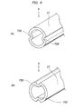
- rigidity adding portions 628 are formed, as portions that add rigidity, by such a manner that the lower part and upper part and the right part and left part of the inflexible tube body 27 are deformed outward as shown in the figure.
- the rigidity adding portions 628 are formed a total of four in number: a pair of upper and lower ones disposed in the direction of the arrow P and a pair of right and left ones (the number is an example).
- the plurality of rigidity adding portions 628 are formed so as to extend straight in the axial direction of the inflexible tube body 27.
- the plurality of rigidity adding portions 628 are formed in the configuration of a ridge (in other words, a rib) that is semicircular in cross section.
- Reference designation 629 represents an anti-chipping portion.
- rigidity adding portions 728 are formed, as portions that add rigidity, by such a manner that the right part and left part of the inflexible tube body 27 are deformed inward as shown in the figure.
- the pair of rigidity adding portions 728 are formed so as to extend straight in the axial direction of the inflexible tube body 27.
- the inflexible tube body 27 is made of, for example, a metal
- the pair of rigidity adding portions 728 are formed in a configuration such that press lines are formed.
- the inflexible tube body 27 is not limited to a metal-made one but may be made of a resin and formed into the configuration shown in Fig. 6(a) by extrusion molding.
- the pair of rigidity adding portions 728 may be disposed on the lower part and upper part of the inflexible tube body 27 as shown in Fig. 6(b) .
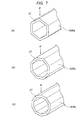
- a rigidity adding portion 828a is formed, as a portion that adds rigidity, such that the inflexible tube body 27 is deformed into, for example, a substantial regular hexagon.
- the rigidity adding portion 828a corresponds to all the part where the inflexible tube body 27 is deformed from the condition of being circular in cross section to the polygon.
- the rigidity adding portion 828a is also formed so that the surface area of the inflexible tube body 27 is large compared with the case of being circular in cross section.
- the rigidity adding portion 828a has a part extending in the direction of the arrow P, this part acts to resist against deformation. Since the surface area is increased in the rigidity adding portion 828a as described above, the heat radiation performance of the inflexible tube body 27 can be enhanced by the increase amount.
- the inflexible tube body 27 may be changed to, for example, a substantial regular octagon as shown in Fig. 7(b) to form a rigidity adding portion 828b. Moreover, the inflexible tube body 27 may be changed to, for example, a substantial regular decagon as shown in Fig. 7(c) to form a rigidity adding portion 828c (the number of angles is an example).
- the inflexible tube body 27 may be changed to, for example, a substantial cross shape as shown in Fig. 8(a) to form a rigidity adding portion 928a. Moreover, the inflexible tube body 27 may be changed to, for example, a substantial star shape as shown in Fig. 8(b) to form a rigidity adding portion 928b.
- the inflexible tube body 27 of the exterior member 16 since at least one rigidity adding portion 28 as a portion that adds rigidity is provided on the inflexible tube body 27 of the exterior member 16, the second moment of area of the inflexible tube body 27 can be increased by the rigidity adding portion 28. Therefore, a necessary and sufficient rigidity is easily secured. Consequently, the inflexible tube body 27 can be reduced in thickness, so that the weight and cost of the wire harness 9 can be reduced.
- the rigidity of the inflexible tube body 27 can be secured by the rigidity adding portion 28, even if the inflexible tube body 27 is reduced in thickness, the inflexible tube body 27 can be prevented from being deformed. Consequently, the workability at the time of manufacture of the wire harness 9 and the workability at the time of fixing of the wire harness 9 to the vehicle underfloor portion 11 and the like can be improved.
- the wire harness 9 and the exterior member 16 according to the embodiment are summarized as follows:
- wire harness exterior member and the wire harness of the present invention are useful in that the wire harness exterior member and the wire harness that enable thickness reduction can be provided.
- 1 hybrid car (car); 2: engine; 3: motor unit; 4: inverter unit; 5: battery; 6: engine room; 7: vehicle rear portion; 8,9: wire harness; 10: intermediate portion; 11: vehicle underfloor portion; 12: junction block; 13: rear end portion; 14: front end portion; 15: high-voltage coaxial composite conducting path (electrically-conducting path); 16: exterior member (wire harness exterior member); 17: first conducting path; 18: first insulator; 19: second conducting path; 20: second insulator; 21: electromagnetic shielding member; 22: sheath; 23: flexible tube portion; 24: inflexible tube portion (straight tube portion); 25: depression; 26: protrusion; 27: inflexible tube body (straight tube body); 28: rigidity adding portion; 29: anti-chipping portion; 30: heat dissipating portion; 128, 228, 328, 428, 528, 628, 728, 828a-c, 928a-b: rigidity adding portion;
Landscapes
- Engineering & Computer Science (AREA)
- Architecture (AREA)
- Civil Engineering (AREA)
- Structural Engineering (AREA)
- Mechanical Engineering (AREA)
- General Engineering & Computer Science (AREA)
- Details Of Indoor Wiring (AREA)
- Protection Of Pipes Against Damage, Friction, And Corrosion (AREA)
Applications Claiming Priority (2)
| Application Number | Priority Date | Filing Date | Title |
|---|---|---|---|
| JP2012183752A JP6089292B2 (ja) | 2012-08-23 | 2012-08-23 | ワイヤハーネス用外装部材及びワイヤハーネス |
| PCT/JP2013/072550 WO2014030739A1 (fr) | 2012-08-23 | 2013-08-23 | Élément extérieur de faisceau électrique et faisceau électrique |
Publications (3)
| Publication Number | Publication Date |
|---|---|
| EP2889973A1 true EP2889973A1 (fr) | 2015-07-01 |
| EP2889973A4 EP2889973A4 (fr) | 2016-04-06 |
| EP2889973B1 EP2889973B1 (fr) | 2023-07-26 |
Family
ID=50150042
Family Applications (1)
| Application Number | Title | Priority Date | Filing Date |
|---|---|---|---|
| EP13830678.2A Active EP2889973B1 (fr) | 2012-08-23 | 2013-08-23 | Élément extérieur de faisceau électrique et faisceau électrique |
Country Status (5)
| Country | Link |
|---|---|
| US (1) | US9735556B2 (fr) |
| EP (1) | EP2889973B1 (fr) |
| JP (1) | JP6089292B2 (fr) |
| CN (1) | CN104604056B (fr) |
| WO (1) | WO2014030739A1 (fr) |
Families Citing this family (10)
| Publication number | Priority date | Publication date | Assignee | Title |
|---|---|---|---|---|
| JP5883486B2 (ja) * | 2014-07-01 | 2016-03-15 | 調和工業株式会社 | 油圧ホース用油漏れ防止材及び油漏れ防止方法並びに杭の施工方法 |
| EP2993749A1 (fr) * | 2014-09-05 | 2016-03-09 | Nexans | Agencement de liaison électrique d'appareils électriques |
| JP5700167B1 (ja) | 2014-11-12 | 2015-04-15 | 住友電装株式会社 | 電線保護パイプおよびワイヤハーネス |
| JP5713139B1 (ja) | 2014-11-12 | 2015-05-07 | 住友電装株式会社 | 電線保護パイプおよびワイヤハーネス |
| JP6292452B2 (ja) * | 2015-05-08 | 2018-03-14 | 株式会社オートネットワーク技術研究所 | シールド導電路 |
| JP6150852B2 (ja) * | 2015-07-13 | 2017-06-21 | 矢崎総業株式会社 | 外装部材及びワイヤハーネス |
| WO2017030157A1 (fr) * | 2015-08-19 | 2017-02-23 | 矢崎総業株式会社 | Élément d'enveloppe de protection externe, faisceau électrique, et procédé de fabrication d'élément d'enveloppe de protection externe |
| JP2017042034A (ja) * | 2015-08-19 | 2017-02-23 | 矢崎総業株式会社 | 外装部材、ワイヤハーネス、及び、外装部材の製造方法 |
| JP6485778B2 (ja) | 2016-06-14 | 2019-03-20 | 矢崎総業株式会社 | ワイヤハーネス |
| JP6590845B2 (ja) * | 2017-02-27 | 2019-10-16 | 矢崎総業株式会社 | 外装部材及びワイヤハーネス |
Family Cites Families (13)
| Publication number | Priority date | Publication date | Assignee | Title |
|---|---|---|---|---|
| FR2831216B1 (fr) * | 2001-10-24 | 2004-01-16 | Wecosta | Conduit d'admission thermoforme en materiau non tisse a double flexions |
| JP3909763B2 (ja) * | 2002-11-20 | 2007-04-25 | 株式会社オートネットワーク技術研究所 | シールド機能を備えた車両用導電路 |
| JP2004173453A (ja) * | 2002-11-21 | 2004-06-17 | Mirai Ind Co Ltd | 保護管連結装置、配線・配管材保護管、連結具及び保護管固定具 |
| JP2004224156A (ja) * | 2003-01-22 | 2004-08-12 | Honda Motor Co Ltd | 車両用電力ケーブル保持構造 |
| EP2096001B1 (fr) | 2006-12-06 | 2012-09-12 | Sumitomo Wiring Systems, Ltd. | Matériau protecteur extérieur pour faisceau de câbles de portière et structure d'agencement de câble pour le faisceau de câbles de portière |
| EP2000723A1 (fr) * | 2007-06-08 | 2008-12-10 | Plastiflex Belgium | Conduite de fluides dotée de sections rigides alternant avec des sections souples |
| JP2009027856A (ja) * | 2007-07-20 | 2009-02-05 | Toyota Motor Corp | 蛇腹チューブ構造 |
| JP2009143326A (ja) * | 2007-12-12 | 2009-07-02 | Sumitomo Wiring Syst Ltd | 三次元姿勢のワイヤハーネスの形成方法、該方法で形成された三次元姿勢のワイヤハーネス、ワイヤハーネスの外装保護材および該外装保護材の製造方法 |
| JP2010013046A (ja) * | 2008-07-07 | 2010-01-21 | Yazaki Corp | ワイヤハーネスの配索構造 |
| JP5576157B2 (ja) * | 2010-03-16 | 2014-08-20 | 矢崎総業株式会社 | ワイヤハーネス及びこの製造方法 |
| FR2962603B1 (fr) * | 2010-07-12 | 2012-07-13 | Peugeot Citroen Automobiles Sa | Cable electrique avec gaine et manchon |
| JP6329726B2 (ja) * | 2012-07-25 | 2018-05-23 | 矢崎総業株式会社 | ワイヤハーネス用外装部材及びワイヤハーネス |
| JP6010820B2 (ja) * | 2012-11-21 | 2016-10-19 | 矢崎総業株式会社 | 電線用外装保護チューブ |
-
2012
- 2012-08-23 JP JP2012183752A patent/JP6089292B2/ja active Active
-
2013
- 2013-08-23 EP EP13830678.2A patent/EP2889973B1/fr active Active
- 2013-08-23 WO PCT/JP2013/072550 patent/WO2014030739A1/fr active Application Filing
- 2013-08-23 CN CN201380044010.9A patent/CN104604056B/zh active Active
-
2015
- 2015-01-22 US US14/602,398 patent/US9735556B2/en active Active
Also Published As
| Publication number | Publication date |
|---|---|
| EP2889973A4 (fr) | 2016-04-06 |
| US9735556B2 (en) | 2017-08-15 |
| EP2889973B1 (fr) | 2023-07-26 |
| WO2014030739A1 (fr) | 2014-02-27 |
| CN104604056A (zh) | 2015-05-06 |
| JP2014042408A (ja) | 2014-03-06 |
| CN104604056B (zh) | 2017-09-29 |
| US20150136481A1 (en) | 2015-05-21 |
| JP6089292B2 (ja) | 2017-03-08 |
Similar Documents
| Publication | Publication Date | Title |
|---|---|---|
| US9735556B2 (en) | Wire harness exterior member and wire harness | |
| EP2894738B1 (fr) | Faisceau électrique | |
| US9742166B2 (en) | Wire harness | |
| JP5231104B2 (ja) | ワイヤハーネス | |
| JP5740146B2 (ja) | ワイヤハーネス | |
| EP2666169B1 (fr) | Chemin conducteur à haute tension et faisceau de câbles | |
| US10242768B2 (en) | Wire harness exterior member and wire harness | |
| JP6240640B2 (ja) | ワイヤハーネス、及びワイヤハーネスの製造方法 | |
| JP2016032388A (ja) | ワイヤハーネス | |
| JP2015201284A (ja) | ワイヤハーネス | |
| US9821733B2 (en) | Wire harness | |
| JP6127312B2 (ja) | ワイヤハーネス | |
| US9963091B2 (en) | Routing configuration of wire harness | |
| US10030794B2 (en) | Corrugated tube and wire harness | |
| US9889805B2 (en) | Wire harness and wire harness manufacturing method | |
| US10322685B2 (en) | Wire harness | |
| JP2016019343A (ja) | ワイヤハーネス用の外装部材、及びワイヤハーネス | |
| JP6145437B2 (ja) | ワイヤハーネス用の外装部材、及びワイヤハーネス | |
| WO2016006638A1 (fr) | Élément de logement pour faisceau de câbles et faisceau de câbles | |
| JP2017054662A (ja) | ワイヤハーネス | |
| WO2016021026A1 (fr) | Faisceau de câbles | |
| JP2017103937A (ja) | ワイヤハーネス |
Legal Events
| Date | Code | Title | Description |
|---|---|---|---|
| PUAI | Public reference made under article 153(3) epc to a published international application that has entered the european phase |
Free format text: ORIGINAL CODE: 0009012 |
|
| 17P | Request for examination filed |
Effective date: 20150206 |
|
| AK | Designated contracting states |
Kind code of ref document: A1 Designated state(s): AL AT BE BG CH CY CZ DE DK EE ES FI FR GB GR HR HU IE IS IT LI LT LU LV MC MK MT NL NO PL PT RO RS SE SI SK SM TR |
|
| AX | Request for extension of the european patent |
Extension state: BA ME |
|
| DAX | Request for extension of the european patent (deleted) | ||
| RA4 | Supplementary search report drawn up and despatched (corrected) |
Effective date: 20160304 |
|
| RIC1 | Information provided on ipc code assigned before grant |
Ipc: B60R 16/02 20060101ALI20160229BHEP Ipc: H02G 3/04 20060101AFI20160229BHEP Ipc: F16L 57/00 20060101ALI20160229BHEP |
|
| STAA | Information on the status of an ep patent application or granted ep patent |
Free format text: STATUS: EXAMINATION IS IN PROGRESS |
|
| 17Q | First examination report despatched |
Effective date: 20170516 |
|
| STAA | Information on the status of an ep patent application or granted ep patent |
Free format text: STATUS: EXAMINATION IS IN PROGRESS |
|
| STAA | Information on the status of an ep patent application or granted ep patent |
Free format text: STATUS: EXAMINATION IS IN PROGRESS |
|
| GRAP | Despatch of communication of intention to grant a patent |
Free format text: ORIGINAL CODE: EPIDOSNIGR1 |
|
| STAA | Information on the status of an ep patent application or granted ep patent |
Free format text: STATUS: GRANT OF PATENT IS INTENDED |
|
| INTG | Intention to grant announced |
Effective date: 20230224 |
|
| GRAJ | Information related to disapproval of communication of intention to grant by the applicant or resumption of examination proceedings by the epo deleted |
Free format text: ORIGINAL CODE: EPIDOSDIGR1 |
|
| STAA | Information on the status of an ep patent application or granted ep patent |
Free format text: STATUS: EXAMINATION IS IN PROGRESS |
|
| INTC | Intention to grant announced (deleted) | ||
| GRAP | Despatch of communication of intention to grant a patent |
Free format text: ORIGINAL CODE: EPIDOSNIGR1 |
|
| STAA | Information on the status of an ep patent application or granted ep patent |
Free format text: STATUS: GRANT OF PATENT IS INTENDED |
|
| INTG | Intention to grant announced |
Effective date: 20230511 |
|
| RAP3 | Party data changed (applicant data changed or rights of an application transferred) |
Owner name: YAZAKI CORPORATION |
|
| GRAS | Grant fee paid |
Free format text: ORIGINAL CODE: EPIDOSNIGR3 |
|
| GRAA | (expected) grant |
Free format text: ORIGINAL CODE: 0009210 |
|
| STAA | Information on the status of an ep patent application or granted ep patent |
Free format text: STATUS: THE PATENT HAS BEEN GRANTED |
|
| AK | Designated contracting states |
Kind code of ref document: B1 Designated state(s): AL AT BE BG CH CY CZ DE DK EE ES FI FR GB GR HR HU IE IS IT LI LT LU LV MC MK MT NL NO PL PT RO RS SE SI SK SM TR |
|
| REG | Reference to a national code |
Ref country code: CH Ref legal event code: EP |
|
| REG | Reference to a national code |
Ref country code: DE Ref legal event code: R096 Ref document number: 602013084325 Country of ref document: DE |
|
| REG | Reference to a national code |
Ref country code: IE Ref legal event code: FG4D |
|
| REG | Reference to a national code |
Ref country code: LT Ref legal event code: MG9D |
|
| REG | Reference to a national code |
Ref country code: NL Ref legal event code: MP Effective date: 20230726 |
|
| PGFP | Annual fee paid to national office [announced via postgrant information from national office to epo] |
Ref country code: FR Payment date: 20230821 Year of fee payment: 11 Ref country code: DE Payment date: 20230816 Year of fee payment: 11 |
|
| REG | Reference to a national code |
Ref country code: AT Ref legal event code: MK05 Ref document number: 1593064 Country of ref document: AT Kind code of ref document: T Effective date: 20230726 |
|
| PG25 | Lapsed in a contracting state [announced via postgrant information from national office to epo] |
Ref country code: NL Free format text: LAPSE BECAUSE OF FAILURE TO SUBMIT A TRANSLATION OF THE DESCRIPTION OR TO PAY THE FEE WITHIN THE PRESCRIBED TIME-LIMIT Effective date: 20230726 |
|
| PG25 | Lapsed in a contracting state [announced via postgrant information from national office to epo] |
Ref country code: GR Free format text: LAPSE BECAUSE OF FAILURE TO SUBMIT A TRANSLATION OF THE DESCRIPTION OR TO PAY THE FEE WITHIN THE PRESCRIBED TIME-LIMIT Effective date: 20231027 |
|
| PG25 | Lapsed in a contracting state [announced via postgrant information from national office to epo] |
Ref country code: IS Free format text: LAPSE BECAUSE OF FAILURE TO SUBMIT A TRANSLATION OF THE DESCRIPTION OR TO PAY THE FEE WITHIN THE PRESCRIBED TIME-LIMIT Effective date: 20231126 |
|
| PG25 | Lapsed in a contracting state [announced via postgrant information from national office to epo] |
Ref country code: SE Free format text: LAPSE BECAUSE OF FAILURE TO SUBMIT A TRANSLATION OF THE DESCRIPTION OR TO PAY THE FEE WITHIN THE PRESCRIBED TIME-LIMIT Effective date: 20230726 Ref country code: RS Free format text: LAPSE BECAUSE OF FAILURE TO SUBMIT A TRANSLATION OF THE DESCRIPTION OR TO PAY THE FEE WITHIN THE PRESCRIBED TIME-LIMIT Effective date: 20230726 Ref country code: PT Free format text: LAPSE BECAUSE OF FAILURE TO SUBMIT A TRANSLATION OF THE DESCRIPTION OR TO PAY THE FEE WITHIN THE PRESCRIBED TIME-LIMIT Effective date: 20231127 Ref country code: NO Free format text: LAPSE BECAUSE OF FAILURE TO SUBMIT A TRANSLATION OF THE DESCRIPTION OR TO PAY THE FEE WITHIN THE PRESCRIBED TIME-LIMIT Effective date: 20231026 Ref country code: LV Free format text: LAPSE BECAUSE OF FAILURE TO SUBMIT A TRANSLATION OF THE DESCRIPTION OR TO PAY THE FEE WITHIN THE PRESCRIBED TIME-LIMIT Effective date: 20230726 Ref country code: LT Free format text: LAPSE BECAUSE OF FAILURE TO SUBMIT A TRANSLATION OF THE DESCRIPTION OR TO PAY THE FEE WITHIN THE PRESCRIBED TIME-LIMIT Effective date: 20230726 Ref country code: IS Free format text: LAPSE BECAUSE OF FAILURE TO SUBMIT A TRANSLATION OF THE DESCRIPTION OR TO PAY THE FEE WITHIN THE PRESCRIBED TIME-LIMIT Effective date: 20231126 Ref country code: HR Free format text: LAPSE BECAUSE OF FAILURE TO SUBMIT A TRANSLATION OF THE DESCRIPTION OR TO PAY THE FEE WITHIN THE PRESCRIBED TIME-LIMIT Effective date: 20230726 Ref country code: GR Free format text: LAPSE BECAUSE OF FAILURE TO SUBMIT A TRANSLATION OF THE DESCRIPTION OR TO PAY THE FEE WITHIN THE PRESCRIBED TIME-LIMIT Effective date: 20231027 Ref country code: FI Free format text: LAPSE BECAUSE OF FAILURE TO SUBMIT A TRANSLATION OF THE DESCRIPTION OR TO PAY THE FEE WITHIN THE PRESCRIBED TIME-LIMIT Effective date: 20230726 Ref country code: AT Free format text: LAPSE BECAUSE OF FAILURE TO SUBMIT A TRANSLATION OF THE DESCRIPTION OR TO PAY THE FEE WITHIN THE PRESCRIBED TIME-LIMIT Effective date: 20230726 |
|
| PG25 | Lapsed in a contracting state [announced via postgrant information from national office to epo] |
Ref country code: PL Free format text: LAPSE BECAUSE OF FAILURE TO SUBMIT A TRANSLATION OF THE DESCRIPTION OR TO PAY THE FEE WITHIN THE PRESCRIBED TIME-LIMIT Effective date: 20230726 |
|
| REG | Reference to a national code |
Ref country code: CH Ref legal event code: PL |
|
| PG25 | Lapsed in a contracting state [announced via postgrant information from national office to epo] |
Ref country code: LU Free format text: LAPSE BECAUSE OF NON-PAYMENT OF DUE FEES Effective date: 20230823 |
|
| PG25 | Lapsed in a contracting state [announced via postgrant information from national office to epo] |
Ref country code: ES Free format text: LAPSE BECAUSE OF FAILURE TO SUBMIT A TRANSLATION OF THE DESCRIPTION OR TO PAY THE FEE WITHIN THE PRESCRIBED TIME-LIMIT Effective date: 20230726 |
|
| PG25 | Lapsed in a contracting state [announced via postgrant information from national office to epo] |
Ref country code: SM Free format text: LAPSE BECAUSE OF FAILURE TO SUBMIT A TRANSLATION OF THE DESCRIPTION OR TO PAY THE FEE WITHIN THE PRESCRIBED TIME-LIMIT Effective date: 20230726 Ref country code: RO Free format text: LAPSE BECAUSE OF FAILURE TO SUBMIT A TRANSLATION OF THE DESCRIPTION OR TO PAY THE FEE WITHIN THE PRESCRIBED TIME-LIMIT Effective date: 20230726 Ref country code: LU Free format text: LAPSE BECAUSE OF NON-PAYMENT OF DUE FEES Effective date: 20230823 Ref country code: ES Free format text: LAPSE BECAUSE OF FAILURE TO SUBMIT A TRANSLATION OF THE DESCRIPTION OR TO PAY THE FEE WITHIN THE PRESCRIBED TIME-LIMIT Effective date: 20230726 Ref country code: EE Free format text: LAPSE BECAUSE OF FAILURE TO SUBMIT A TRANSLATION OF THE DESCRIPTION OR TO PAY THE FEE WITHIN THE PRESCRIBED TIME-LIMIT Effective date: 20230726 Ref country code: DK Free format text: LAPSE BECAUSE OF FAILURE TO SUBMIT A TRANSLATION OF THE DESCRIPTION OR TO PAY THE FEE WITHIN THE PRESCRIBED TIME-LIMIT Effective date: 20230726 Ref country code: CZ Free format text: LAPSE BECAUSE OF FAILURE TO SUBMIT A TRANSLATION OF THE DESCRIPTION OR TO PAY THE FEE WITHIN THE PRESCRIBED TIME-LIMIT Effective date: 20230726 Ref country code: CH Free format text: LAPSE BECAUSE OF NON-PAYMENT OF DUE FEES Effective date: 20230831 Ref country code: SK Free format text: LAPSE BECAUSE OF FAILURE TO SUBMIT A TRANSLATION OF THE DESCRIPTION OR TO PAY THE FEE WITHIN THE PRESCRIBED TIME-LIMIT Effective date: 20230726 Ref country code: MC Free format text: LAPSE BECAUSE OF FAILURE TO SUBMIT A TRANSLATION OF THE DESCRIPTION OR TO PAY THE FEE WITHIN THE PRESCRIBED TIME-LIMIT Effective date: 20230726 |
|
| REG | Reference to a national code |
Ref country code: BE Ref legal event code: MM Effective date: 20230831 |
|
| REG | Reference to a national code |
Ref country code: IE Ref legal event code: MM4A |