EP2889663B1 - Driving apparatus, and lens apparatus and image pickup apparatus including the same - Google Patents
Driving apparatus, and lens apparatus and image pickup apparatus including the same Download PDFInfo
- Publication number
- EP2889663B1 EP2889663B1 EP14004321.7A EP14004321A EP2889663B1 EP 2889663 B1 EP2889663 B1 EP 2889663B1 EP 14004321 A EP14004321 A EP 14004321A EP 2889663 B1 EP2889663 B1 EP 2889663B1
- Authority
- EP
- European Patent Office
- Prior art keywords
- motor
- information
- optical member
- movable optical
- drive
- Prior art date
- Legal status (The legal status is an assumption and is not a legal conclusion. Google has not performed a legal analysis and makes no representation as to the accuracy of the status listed.)
- Active
Links
Images


Classifications
-
- G—PHYSICS
- G02—OPTICS
- G02B—OPTICAL ELEMENTS, SYSTEMS OR APPARATUS
- G02B7/00—Mountings, adjusting means, or light-tight connections, for optical elements
- G02B7/02—Mountings, adjusting means, or light-tight connections, for optical elements for lenses
- G02B7/04—Mountings, adjusting means, or light-tight connections, for optical elements for lenses with mechanism for focusing or varying magnification
- G02B7/09—Mountings, adjusting means, or light-tight connections, for optical elements for lenses with mechanism for focusing or varying magnification adapted for automatic focusing or varying magnification
-
- G—PHYSICS
- G02—OPTICS
- G02B—OPTICAL ELEMENTS, SYSTEMS OR APPARATUS
- G02B7/00—Mountings, adjusting means, or light-tight connections, for optical elements
- G02B7/02—Mountings, adjusting means, or light-tight connections, for optical elements for lenses
- G02B7/04—Mountings, adjusting means, or light-tight connections, for optical elements for lenses with mechanism for focusing or varying magnification
- G02B7/10—Mountings, adjusting means, or light-tight connections, for optical elements for lenses with mechanism for focusing or varying magnification by relative axial movement of several lenses, e.g. of varifocal objective lens
- G02B7/102—Mountings, adjusting means, or light-tight connections, for optical elements for lenses with mechanism for focusing or varying magnification by relative axial movement of several lenses, e.g. of varifocal objective lens controlled by a microcomputer
-
- G—PHYSICS
- G03—PHOTOGRAPHY; CINEMATOGRAPHY; ANALOGOUS TECHNIQUES USING WAVES OTHER THAN OPTICAL WAVES; ELECTROGRAPHY; HOLOGRAPHY
- G03B—APPARATUS OR ARRANGEMENTS FOR TAKING PHOTOGRAPHS OR FOR PROJECTING OR VIEWING THEM; APPARATUS OR ARRANGEMENTS EMPLOYING ANALOGOUS TECHNIQUES USING WAVES OTHER THAN OPTICAL WAVES; ACCESSORIES THEREFOR
- G03B13/00—Viewfinders; Focusing aids for cameras; Means for focusing for cameras; Autofocus systems for cameras
- G03B13/32—Means for focusing
- G03B13/34—Power focusing
-
- H—ELECTRICITY
- H04—ELECTRIC COMMUNICATION TECHNIQUE
- H04N—PICTORIAL COMMUNICATION, e.g. TELEVISION
- H04N23/00—Cameras or camera modules comprising electronic image sensors; Control thereof
- H04N23/60—Control of cameras or camera modules
- H04N23/69—Control of means for changing angle of the field of view, e.g. optical zoom objectives or electronic zooming
Definitions
- the present invention relates to a driving apparatus, and more particularly, to a driving apparatus configured to drive a lens, and a lens apparatus and an image pickup apparatus including the lens driving apparatus.
- a lens position is detected by a position detector, and a control signal for eliminating a difference between the detected position and a target position determined based on a position command value is transmitted to a motor, to thereby drive the lens toward the target position (position feedback control). Further, a lens speed determined based on the position detected by the position detector is reflected on a value to be output to the motor, to thereby drive the lens at a constant speed (speed feedback control).
- the position detector configured to detect the lens position is influenced by a backlash of a gear train of a lens driving mechanism, and hence the rotational position and rotational speed of a motor derived based on detection results of the position detector are inaccurate.
- the rotational speed of motor is to be controlled based on the detection signal, an unintended control signal is transmitted to the motor.
- the position detector does not generate any signal immediately due to the backlash.
- a drive signal is continuously transmitted to the motor until the backlash is eliminated and then a signal is generated by the position detector.
- the rotational speed of motor is increased excessively, which may cause an operator to feel uncomfortable with an image at the start of lens movement.
- US 6,085,044 discloses an optical apparatus with a lens unit, a driving mechanism for moving the lens unit, a detecting means for detecting a position of the lens unit and a detecting means for detecting a driving direction of the lens unit. Further disclosed is a control device for controlling the driving mechanism that stores a correction value corresponding to an amount of a play of the driving mechanism at each lens unit position and corrects the driving of the driving mechanism using the correction value based on a detected position and a driving direction of the lens unit.
- a first pulse generator configured to generate a pulse in response to lens movement
- a second pulse generator configured to generate a pulse in response to motor drive.
- the system is configured to control the drive amount of the lens based on an output from the first pulse generator, and to control the rotational speed of motor based on an output from the second pulse generator.
- a driving apparatus capable of performing accurate lens drive control, and to provide a lens apparatus and an image pickup apparatus including the lens driving apparatus.
- a driving apparatus as defined in claim 1.
- a driving apparatus as defined in claim 2.
- FIG. 1 illustrates a configuration of a lens apparatus according to a first embodiment which does not describe the invention.
- the lens apparatus includes a lens barrel 100 and a drive apparatus 200.
- the lens barrel 100 includes a zoom lens operation portion 101 illustrated in FIG. 1 , an image pickup optical system including optical adjusting members such as a zoom lens 102, a focus lens (not shown), and an iris (not shown), and an operation unit for the optical adjusting members.
- the zoom lens 102 being one of the optical adjusting members is hereinafter described as a movable optical member to be driven in the present invention.
- the drive apparatus 200 includes a motor 201 (drive unit), a CPU 202, an operation portion 203, a position detector 204 (position detector), a motor electric current detector 205, and a drive circuit 209.
- the CPU 202 includes a feedback signal calculator 206 (first deriving unit), a feedback signal switching portion 207 (selection unit), and a feedback controller 208 (controller).
- the zoom lens operation portion 101 of the lens barrel 100 transmits a drive force from the outside to the zoom lens 102 so as to move the zoom lens 102 in an optical axis direction, to thereby change a focal length.
- the zoom lens operation portion 101 is constructed of, for example, a zoom operating ring.
- the operation portion 203 of the drive apparatus 200 is operated by the operator, and outputs a command signal.
- the command signal includes a command information to direct the driving of the zoom lens 102.
- the command information is information to direct a drive direction and a drive speed (that may be a drive amount and a drive position).
- the position detector 204 is connected to the zoom lens operation portion 101 through intermediation of a gear train, and generates a pulse in accordance with a movement amount of the zoom lens operation portion 101.
- the generated pulse is used for deriving a position and speed of the zoom lens (movable optical member) 102 which is a first information by the feedback signal calculator (first deriving unit) 206 described later.
- a configuration for reducing a backlash that may be generated therebetween is employed.
- a scissors gear having two gears biased with a spring and engaged with a mating gear in a sandwiching manner, to thereby eliminate the backlash.
- the position detector 204 is moved in association with the movement of the zoom lens operation portion 101, and hence, when a mechanism such as the scissors gear is applied, the position of the zoom lens operation portion 101 can be detected without the backlash.
- the motor 201 is also engaged with the zoom lens operation portion 101 through intermediation of gears.
- the drive force output from the motor 201 so as to drive the zoom lens 102 is transmitted to the zoom lens operation portion 101.
- the scissors gear may also be employed at a gear engagement portion between the motor 201 and the zoom lens operation portion 101, but when the rotational load of the motor 201 is significant, the effect of reducing the backlash by the scissors gear cannot be attained substantially.
- the motor 201 has a backlash of a reduction gear train (not shown), and hence the backlash between the motor 201 and the zoom lens operation portion 101 cannot be eliminated.
- the motor electric current detector 205 detects an electric current flowing when the motor 201 is driven. For example, the motor electric current detector 205 detects a voltage at both ends of a resistor (not shown) connected to the motor 201 in series, and divides the voltage by a resistance value of the resistor, to thereby detect the electric current flowing through the motor 201. The detected electric current is used by the feedback signal calculator (first deriving unit) 206 described later for deriving a rotational position and rotational speed of the motor 201 which is a second information.
- the feedback signal calculator first deriving unit
- the feedback controller 208 performs position feedback control and speed feedback control based on a feedback signal output from the feedback signal switching portion 207 described later, and on the command signal (including the command information) output from the operation portion 203, to thereby generate a drive signal.
- the drive circuit 209 amplifies the drive signal output from the feedback controller 208 via a D/A converter (not shown), to thereby drive the motor 201.
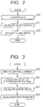
- FIG. 2 is a flow chart illustrating calculation (derivation) of the position and speed of the zoom lens 102 (first information) based on the output from the position detector 204 that is set as the information included in the feedback signal.
- Step S10 the CPU 202 counts the pulses output from the position detector 204.
- Step S11 the CPU 202 derives(calculates) the position of the zoom lens 102 based on the number of pulses counted in Step S10, and then the processing proceeds to Step S12.
- Step S12 the CPU 202 differentiates the position of the zoom lens 102 that is derived in Step S11, to thereby derive the speed of the zoom lens 102.
- the CPU 202 repeats the above-mentioned processing in a predetermined sampling period, to thereby detect the position and speed of the zoom lens 102.
- the position and speed of the zoom lens 102 are accurately derived through the flow illustrated in FIG. 2 because of the configuration in which the part between the zoom lens operation portion 101 and the position detector 204 is not influenced by the backlash.
- the motor 201 is engaged with the zoom lens operation portion 101 through intermediation of the gears, and hence, also through association between the rotational position and rotational speed of the motor 201 and the rotational position and rotational speed of the zoom lens 102, the position and speed of the zoom lens 102 may be obtained based on the rotational position and speed of the motor 201.
- the backlash is generated between the zoom lens operation portion 101 and the motor 201, and hence the position and speed of the zoom lens 102 that are obtained based on the pulses output from the position detector 204 do not necessarily correspond, on a one-to-one correspondence basis, to the position and speed of the zoom lens 102 that are obtained based on the rotational position and rotational speed of the motor 201 derived based on the electric current determined by the motor electric current detector 205.
- FIG. 3 is a flow chart illustrating calculation (derivation) of the rotational position and rotational speed of the motor 201 (second information) based on the output from the motor electric current detector 205 that is set as the feedback signal.
- Step S20 the processing of the CPU 202 proceeds to Step S20.
- Step S20 the CPU 202 obtains the electric current determined by the motor electric current detector 205.
- Step S21 the CPU 202 derives a counter-electromotive voltage of the motor 201, and then the processing proceeds to Step S22.
- the CPU 202 derives the counter-electromotive voltage by a method described later. Due to the fact that the counter-electromotive voltage is proportional to the rotational speed of the motor, in Step S22, the CPU 202 determines the rotational speed of the motor 201 by multiplying the counter-electromotive voltage by a proportionality constant determined in advance, and then the processing proceeds to Step S23.
- Step S23 the CPU 202 integrates the rotational speed of the motor, to thereby derive the rotational position of the motor.
- the CPU 202 repeats the above-mentioned processing in a predetermined sampling period, to thereby detect the rotational position and rotational speed of the motor 201.
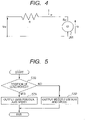
- FIG. 4 is a diagram illustrating a simple equivalent circuit of the drive circuit 209 of FIG. 1 .
- Vm represents a voltage applied to the motor 201; I, a motor electric current flowing through the motor 201; Vr, a counter-electromotive voltage of the motor 201; Rm, an internal resistance of the motor 201; and R, a resistance component of the simple equivalent circuit.
- I a motor electric current flowing through the motor 201
- Vr a counter-electromotive voltage of the motor 201
- Rm an internal resistance of the motor 201
- R a resistance component of the simple equivalent circuit.
- Vr Vm ⁇ R + Rm ⁇ I
- the voltage Vm is determined based on the drive signal generated by the feedback controller 208, and the motor electric current I is detected by the motor electric current detector 205. Further, the value (R+Rm) is a known value, and hence stored and held in advance. Under those conditions, the counter-electromotive voltage can be derived based on Expression (1).
- the rotational position and rotational speed of the motor 201 are accurately derived through the flow illustrated in FIG. 3 because of the calculation (derivation) based on the motor electric current generated in response to the rotation of the motor 201.
- the signal including the zoom lens position and speed (first information) and the rotational position and rotational speed of the motor (second information), which is derived in the manner described above, is input as a feedback signal to the feedback signal switching portion 207 described later.
- Step S30 the processing of the CPU 202 proceeds to Step S31 when the zoom lens position derived by the feedback signal calculator (first deriving unit) 206 is changed (that is, when the position of the zoom lens is changed), whereas the processing proceeds to Step S32 when the zoom lens position derived by the feedback signal calculator 206 is not changed (that is, when the position of the zoom lens is not changed). Whether or not the position of the zoom lens is changed is determined by the feedback signal switching portion 207 based on the pulse signal from the position detector 204.
- Step S31 the CPU 202 outputs, to the feedback controller 208, the zoom lens position and speed (first information) derived through the flow illustrated in FIG. 2 .
- Step S32 the CPU 202 outputs, to the feedback controller 208, the signal including the rotational position and rotational speed of the motor (second information) derived through the flow illustrated in FIG. 3 .
- the CPU 202 repeats the above-mentioned processing in a predetermined sampling period.
- the drive signal when the position of the zoom lens 102 is changed, the drive signal is generated based on the zoom lens position and speed, whereas when the position of the zoom lens 102 is not changed, the drive signal is generated based on the rotational position and rotational speed of the motor.
- the feedback signal switching portion 207 determines whether or not the position of the zoom lens 102 is changed.
- the motor drive is controlled based on the signal including the rotational position and rotational speed of the motor 201 (second information) that are set as the feedback signal
- the motor drive is controlled based on the signal including the position and speed of the zoom lens 102 (first information) that are set as the feedback signal.
- the signal including the zoom lens position and speed (fist information) is output to the feedback controller 208 as the feedback signal irrespective of whether or not the motor 201 is rotated through the backlash area. Therefore, during a period in which the motor 201 is rotated through the backlash area, an unintended drive signal is transmitted to the motor, which may cause the operator to feel uncomfortable with an image at the start of lens movement. That is, even when the control signal for driving the motor is output, the zoom lens to be driven is not moved, and hence a command for driving the motor to a higher degree is output, with the result that the lens may start to be moved with a shock after the backlash is eliminated.
- the signal including the rotational position and rotational speed of the motor (second information) is set as the feedback signal. Therefore, a drive signal that is not influenced by the backlash can be transmitted to the motor, thereby attaining an effect of solving the above-mentioned problem inherent in the related art. That is, during a period in which the zoom lens position and speed are not changed but the rotational position and rotational speed of the motor are changed, the CPU 202 can perform the drive control while recognizing that the control is performed during the period in which the motor 201 is rotated through the backlash area.
- the rotational position and rotational speed of the motor 201 are derived inside the CPU 202 through the detection of the electric current flowing through the motor 201, and hence there is no need to employ a position detector therefor.
- the object can be achieved whereby the driving apparatus capable of suppressing the influence of the backlash of the gear train of the lens operation portion can be provided without upsizing the drive apparatus and increasing the manufacturing cost due to the increase in number of hardware components.
- the zoom lens is taken as an example of the optical adjusting member to be driven.
- the optical adjusting member is not limited thereto, and may also be applicable to the focus lens and the iris.
- the signal including both the position and the speed is set as the feedback signal.
- the feedback signal is not limited thereto, and signal including only the speed or the position may be set as the feedback signal.
- the feedback signal switching portion 207 determines whether or not the motor 201 is rotated through the backlash area, to thereby switch between the signal including the zoom lens position and speed (first information) and the signal including the rotational position and rotational speed of the motor (second information) to use as the feedback signal for the drive control.
- the feedback signal switching portion 207 compares a driving direction indicated by the command information and a drive direction of the zoom lens operation portion 101 in the previous operation. Based on a result of the comparison, the feedback signal switching portion 207 switches between the zoom lens position and speed (first information) and the rotational position and rotational speed of the motor (second information) to use as the feedback signal for the drive control.
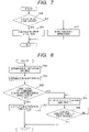
- FIG. 6 illustrates a system configuration of the driving apparatus according to this embodiment. Note that, components similar to those of the first embodiment illustrated in FIG. 1 are represented by the same reference symbols, and description thereof is therefore omitted herein.
- a drive direction calculator (second deriving unit) 210 of FIG. 6 derives a drive direction of the zoom lens operation portion 101 when the zoom lens operation portion 101 is driven. Now, a flow of processing to be performed by the drive direction calculator 210 is described with reference to FIG. 7 .
- Step S40 the processing proceeds to Step S41 when the zoom lens position derived by the feedback signal calculator 206 was changed (when the position of the zoom lens was changed), whereas the processing proceeds to Step S42 when the zoom lens position derived by the feedback signal calculator 206 was not changed (when the position of the zoom lens was not changed).
- Step S41 based on the change in zoom lens position derived by the feedback signal calculator 206, the CPU 202 determines whether the drive direction is a telephoto direction or a wide-angle direction.
- Step S42 the CPU 202 updates and maintains the drive direction as the direction that is most recently determined in Step S41.
- the CPU 202 repeats the above-mentioned processing in a predetermined sampling period.
- Step S50 the processing of the CPU 202 proceeds to Step S50.
- Step S50 the CPU 202 obtains the drive direction maintained by the drive direction calculator 210 (derived by the drive direction deriving unit 210), and then the processing proceeds to Step S51.
- Step S51 the CPU 202 obtains a command signal (command information) output from the operation portion 203, and then the processing proceeds to Step S52.
- Step S52 the CPU 202 compares the drive direction of the zoom lens operation portion 101 that is obtained in Step S50 and the drive direction indicated by the command signal (command information) that is obtained in Step S51.
- the processing proceeds to Step S53 when both the directions match with each other, whereas the processing proceeds to Step S54 when both the directions differ from each other.
- Step S53 the CPU 202 outputs the zoom lens position and speed derived by the feedback signal calculator 206.
- Step S54 the CPU 202 outputs the rotational position and rotational speed of the motor derived by the feedback signal calculator 206, and then the processing proceeds to Step S55.
- Step S55 the processing is ended when a predetermined time period has elapsed, whereas the processing of Step S54 is repeated when the predetermined time period has not elapsed. Note that, the predetermined time period in this case is set as a time period in which the backlash is eliminated.
- Step S55 whether or not the backlash is eliminated is determined based on whether or not the predetermined time period has elapsed, but the determination is not limited thereto. Whether or not the backlash is eliminated may be determined based on whether or not the motor 201 is rotated by a predetermined amount.
- the zoom lens operation portion 101 when the zoom lens operation portion 101 is to be driven in response to the command signal (command information) transmitted to the drive apparatus 200, the drive direction of the zoom lens operation portion 101 in the previous operation and the drive direction in which the zoom lens is driven by the transmitted command signal (command information) are compared to each other. As a result of the comparison, when both the directions match with each other, it is determined that the motor 201 is not rotated through the backlash area. When both the directions differ from each other, on the other hand, it is determined that the motor 201 is rotated through the backlash area and the drive force is then transmitted from the motor 201 to the zoom lens operation portion 101.
- FIGS. 9 and 10 an II embodiment of the present invention is described with reference to FIGS. 9 and 10 .
- the feedback signal switching portion 207 determines whether or not the motor 201 is rotated through the backlash area.
- the feedback signal switching portion 207 compares a drive direction indicated by the command signal (command information) and a gravity direction of the zoom lens 102. Based on a result of the comparison, the feedback signal switching portion 207 switches whether to output the zoom lens position and speed or the rotational position and rotational speed of the lens.
- the feedback signal switching portion 207 outputs a signal including the zoom lens position and speed (first information) as the feedback signal.
- the feedback signal switching portion 207 when an electric current limiting circuit is configured, in order to eliminate influence of erroneous detection of the counter-electromotive voltage at the time when the electric current value has reached a limit value, the feedback signal switching portion 207 outputs a signal including the zoom lens position and speed (first information) as the feedback signal.
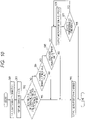
- FIG. 9 a system configuration diagram of a driving apparatus according to this embodiment illustrated in FIG. 9 is described. Note that, components similar to those of the first embodiment illustrated in FIG. 1 are represented by the same reference symbols, and description thereof is therefore omitted herein.
- An inclination detector 211 is configured in the drive apparatus 200 so as to detect inclination of the drive apparatus 200.
- examples of the inclination detector 211 as used herein include a publiclyknown acceleration sensor.
- the inclination detector 211 is configured in the drive apparatus 200, but is not limited thereto.
- the inclination detector 211 may be configured in the lens barrel 100.
- An electric current limiting circuit 212 is configured in the drive apparatus (limiter) 200.
- the drive apparatus 200 is configured to limit the electric current when the electric current is equal to or more than an upper limit of power consumption that is set in advance.
- the electric current limiting circuit 212 adjusts the voltage to be applied to the motor 201, to thereby limit the electric current flowing through the motor 201 to be less than the electric current limit value.
- Step S60 the processing of the CPU 202 proceeds to Step S60.
- Step S60 the CPU 202 derives the gravity direction of the zoom lens 102 based on the inclination of the drive apparatus 200 that is output from the inclination detector 211, and then the processing proceeds to Step S61.
- Step S61 the CPU 202 obtains a command signal (command information) output from the operation portion 203, and then the processing proceeds to Step S62.
- Step S62 the CPU 202 compares the gravity direction of the lens that is derived in Step S60 and the drive direction indicated by the command signal (command information) that is obtained in Step S61.
- the processing proceeds to Step S63 when both the directions differ from each other, whereas the processing proceeds to Step S64 when both the directions match with each other.
- Step S64 the processing proceeds to Step S63 when the drive speed indicated by the command signal (command information) is equal to or less than a predetermined threshold value described later, whereas the processing proceeds to Step S65 when the speed indicated by the command signal is more than the predetermined threshold value.
- the predetermined threshold value is set by determining in advance such a speed that the response of the zoom lens operation portion 101 does not cause the operator to feel uncomfortable with the operation.
- Step S65 the processing proceeds to Step S63 when the electric current detected by the motor electric current detector 205 has reached the electric current limit value, whereas the processing proceeds to Step S66 when the electric current detected by the motor electric current detector 205 has not reached the electric current limit value.
- the CPU 202 outputs a signal including the rotational position and rotational speed of the motor (second information) derived by the feedback signal calculator 206, and then the processing proceeds to Step S67.
- Step S67 the processing is ended when a predetermined time period has elapsed, whereas the processing of Step S66 is repeated when the predetermined time period has not elapsed.
- the predetermined time period in this case is set as a time period in which the backlash is eliminated.
- the determination of whether or not the backlash is eliminated is not limited to the determination based on the elapse of the predetermined time period, and may be performed based on whether or not the motor 201 is rotated by a predetermined amount.
- the feedback signal switching portion 207 selects the signal including the position and speed of the zoom lens (movable optical member) (first information) as the feedback signal when the drive direction indicated by the command information, which is derived based on the inclination of the installation posture of the drive apparatus 200, does not have a component in a vertically downward direction (gravity drop direction). Further, the feedback signal switching portion 207 selects the signal including the rotational position and rotational speed of the motor (drive unit) (second information) as the feedback signal when the drive direction indicated by the command information has the component in the vertically downward direction.
- the zoom lens operation portion 101 when the zoom lens operation portion 101 is to be driven under a state in which the driving apparatus is inclined, the gravity direction of the zoom lens 102 and the drive direction indicated by the transmitted command signal are compared to each other.
- the driving apparatus is used in a state of being inclined significantly, due to the self-weight of the zoom lens 102, the meshing between the zoom lens operation portion 101 and the gear connected thereto is determined uniquely depending on the gravity direction. That is, when the zoom lens operation portion 101 is to be driven in the same direction as the gravity direction of the zoom lens 102, the motor 201 is rotated through the backlash area.
- the motor 201 is not rotated through the backlash area.
- the zoom lens 102 through the comparison between the gravity direction of the zoom lens 102 and the drive direction indicated by the command signal (command information), it can be determined whether or not the motor 201 is rotated through the backlash area. Based on the determination, it is switched whether to output the zoom lens position and speed or the rotational position and rotational speed of the motor, thereby being capable of attaining an effect equivalent to that of the first embodiment.
- a time period required until the drive force is transmitted to the zoom lens operation portion 101 is longer, with the result that the drive response is decreased.
- a signal including the zoom lens position and speed is set as the feedback signal.
- the feedback signal switching portion 207 when the electric current detected by the motor electric current detector 205 has reached the electric current limit value set in advance, the feedback signal switching portion 207 outputs a signal including the zoom lens position and speed (first information) to the feedback controller 208 as the feedback signal.
- the electric current limiting circuit 212 suppresses the voltage to be applied to the motor 201.
- the voltage to be derived based on the drive signal output from the feedback controller 208 and the voltage to be applied to the motor 201 differ from each other, with the result that the feedback signal calculator 206 may derive a different value from that of an actually generated counter-electromotive voltage.
- a lens apparatus including the driving apparatus as described above, and further constructing an image pickup apparatus including the lens apparatus and an image pickup element configured to receive light from the lens apparatus, it is possible to attain such an effect that the influence of the backlash of the gear train of the lens operation portion is suppressed without upsizing the drive apparatus and increasing the manufacturing cost due to the increase in number of hardware components.
Landscapes
- Physics & Mathematics (AREA)
- General Physics & Mathematics (AREA)
- Optics & Photonics (AREA)
- Engineering & Computer Science (AREA)
- General Engineering & Computer Science (AREA)
- Multimedia (AREA)
- Signal Processing (AREA)
- Lens Barrels (AREA)
Applications Claiming Priority (1)
| Application Number | Priority Date | Filing Date | Title |
|---|---|---|---|
| JP2013268341A JP6351258B2 (ja) | 2013-12-26 | 2013-12-26 | レンズ駆動装置及びそれを有するレンズ装置及び撮像装置 |
Publications (2)
| Publication Number | Publication Date |
|---|---|
| EP2889663A1 EP2889663A1 (en) | 2015-07-01 |
| EP2889663B1 true EP2889663B1 (en) | 2022-09-28 |
Family
ID=52349914
Family Applications (1)
| Application Number | Title | Priority Date | Filing Date |
|---|---|---|---|
| EP14004321.7A Active EP2889663B1 (en) | 2013-12-26 | 2014-12-19 | Driving apparatus, and lens apparatus and image pickup apparatus including the same |
Country Status (4)
| Country | Link |
|---|---|
| US (1) | US9664876B2 (enExample) |
| EP (1) | EP2889663B1 (enExample) |
| JP (1) | JP6351258B2 (enExample) |
| RU (1) | RU2014153047A (enExample) |
Families Citing this family (1)
| Publication number | Priority date | Publication date | Assignee | Title |
|---|---|---|---|---|
| JP7558762B2 (ja) * | 2020-11-10 | 2024-10-01 | キヤノン株式会社 | 雲台及び撮像装置 |
Family Cites Families (16)
| Publication number | Priority date | Publication date | Assignee | Title |
|---|---|---|---|---|
| US4881799A (en) * | 1987-04-20 | 1989-11-21 | Ricoh Company, Ltd. | Varifocal lens device |
| US5463442A (en) * | 1988-08-31 | 1995-10-31 | Canon Kabushiki Kaisha | Interchangeable lens unit for use in camera system |
| JP2824792B2 (ja) * | 1989-09-30 | 1998-11-18 | 株式会社リコー | レンズ駆動制御装置 |
| JPH0460508A (ja) * | 1990-06-28 | 1992-02-26 | Nikon Corp | レンズ駆動装置 |
| JPH05137360A (ja) * | 1991-11-07 | 1993-06-01 | Canon Inc | 振動波モーターを用いた目標物駆動装置 |
| US5932984A (en) * | 1995-09-04 | 1999-08-03 | Canon Kabushiki Kaisha | Driving apparatus and optical apparatus |
| JP3869884B2 (ja) * | 1996-04-11 | 2007-01-17 | キヤノン株式会社 | レンズ鏡筒および光学機器 |
| JP4717263B2 (ja) * | 2001-05-29 | 2011-07-06 | キヤノン株式会社 | レンズ鏡筒およびカメラ |
| JP4058375B2 (ja) * | 2003-04-17 | 2008-03-05 | 株式会社フジクラ | 光ファイバ収納ケース及び光ファイバ収納ケースを備えた装置 |
| KR100733258B1 (ko) * | 2003-04-17 | 2007-06-27 | 니혼 덴산 산쿄 가부시키가이샤 | 렌즈 구동장치,박형 카메라 및 카메라 부착 휴대 전화기 |
| JP4590190B2 (ja) * | 2004-01-30 | 2010-12-01 | キヤノン株式会社 | 光学機器 |
| JP2010185892A (ja) * | 2007-05-28 | 2010-08-26 | Panasonic Corp | カメラシステムおよびカメラ本体 |
| FR2922695A1 (fr) * | 2007-10-22 | 2009-04-24 | St Microelectronics Grenoble | Circuit de commande de moteur a bobine mobile |
| US8964102B2 (en) * | 2011-06-29 | 2015-02-24 | Maxim Integrated Products, Inc. | Self-calibrated ringing compensation for an autofocus actuator in a camera module |
| JP2013105161A (ja) * | 2011-11-17 | 2013-05-30 | Olympus Corp | 駆動装置、撮像装置、ぶれ補正装置、駆動方法、制御プログラム、及び制御プログラムを記録する記録媒体 |
| JP2014171344A (ja) * | 2013-03-05 | 2014-09-18 | Hitachi Ltd | 撮像装置、モータ駆動装置、および撮像方法 |
-
2013
- 2013-12-26 JP JP2013268341A patent/JP6351258B2/ja active Active
-
2014
- 2014-12-19 EP EP14004321.7A patent/EP2889663B1/en active Active
- 2014-12-22 US US14/578,822 patent/US9664876B2/en active Active
- 2014-12-25 RU RU2014153047A patent/RU2014153047A/ru not_active Application Discontinuation
Also Published As
| Publication number | Publication date |
|---|---|
| EP2889663A1 (en) | 2015-07-01 |
| US20150185432A1 (en) | 2015-07-02 |
| US9664876B2 (en) | 2017-05-30 |
| RU2014153047A (ru) | 2016-07-20 |
| JP2015125211A (ja) | 2015-07-06 |
| JP6351258B2 (ja) | 2018-07-04 |
Similar Documents
| Publication | Publication Date | Title |
|---|---|---|
| US8964105B2 (en) | Auto-focus controlling apparatus, electronic imaging apparatus and digital still camera | |
| US8755127B2 (en) | Optical apparatus | |
| US20090190910A1 (en) | Focus controller and optical apparatus using the same | |
| CN106054350B (zh) | 光学装置和显示控制方法 | |
| JP2014178639A5 (enExample) | ||
| KR20120021204A (ko) | 제어 장치, 제어 방법 및 제어 장치를 포함하는 안과 장치 | |
| JP2013117613A5 (ja) | カメラシステム、交換レンズ、およびカメラ | |
| US10715064B2 (en) | Control device, optical device, control method, and storage medium | |
| US8526805B2 (en) | Lens apparatus and camera system including the same | |
| EP2889663B1 (en) | Driving apparatus, and lens apparatus and image pickup apparatus including the same | |
| US11336811B2 (en) | Operation apparatus, optical apparatus, and image pickup apparatus | |
| US10209482B2 (en) | Lens control device, imaging apparatus, lens device, imaging system, and method of controlling lens control device | |
| JP5350029B2 (ja) | 光学機器 | |
| KR20130053043A (ko) | 스테핑 모터 제어 장치 및 방법 | |
| JP4733457B2 (ja) | 駆動装置 | |
| US8711490B2 (en) | Lens system | |
| US7755695B2 (en) | Camera system and lens apparatus | |
| JP2015171238A (ja) | ステッピングモータ制御装置、駆動装置、光学機器、撮像装置、およびステッピングモータ制御方法 | |
| JP5355119B2 (ja) | 撮像装置、撮像装置の制御方法、及び撮像装置の制御プログラム | |
| JP2017026770A (ja) | レンズ鏡筒のマニュアルフォーカス制御、及び電子表示手段 | |
| JP2013238746A (ja) | カメラ本体及びカメラシステム | |
| US20200007776A1 (en) | Lens apparatus and image pickup apparatus | |
| US11388342B2 (en) | Operation apparatus, lens apparatus, and image pickup apparatus | |
| JP2017215404A (ja) | レンズ駆動装置 | |
| US11454788B2 (en) | Optical apparatus, control method, and storage medium |
Legal Events
| Date | Code | Title | Description |
|---|---|---|---|
| PUAI | Public reference made under article 153(3) epc to a published international application that has entered the european phase |
Free format text: ORIGINAL CODE: 0009012 |
|
| 17P | Request for examination filed |
Effective date: 20141219 |
|
| AK | Designated contracting states |
Kind code of ref document: A1 Designated state(s): AL AT BE BG CH CY CZ DE DK EE ES FI FR GB GR HR HU IE IS IT LI LT LU LV MC MK MT NL NO PL PT RO RS SE SI SK SM TR |
|
| AX | Request for extension of the european patent |
Extension state: BA ME |
|
| R17P | Request for examination filed (corrected) |
Effective date: 20160104 |
|
| RBV | Designated contracting states (corrected) |
Designated state(s): AL AT BE BG CH CY CZ DE DK EE ES FI FR GB GR HR HU IE IS IT LI LT LU LV MC MK MT NL NO PL PT RO RS SE SI SK SM TR |
|
| STAA | Information on the status of an ep patent application or granted ep patent |
Free format text: STATUS: EXAMINATION IS IN PROGRESS |
|
| 17Q | First examination report despatched |
Effective date: 20190509 |
|
| GRAP | Despatch of communication of intention to grant a patent |
Free format text: ORIGINAL CODE: EPIDOSNIGR1 |
|
| STAA | Information on the status of an ep patent application or granted ep patent |
Free format text: STATUS: GRANT OF PATENT IS INTENDED |
|
| INTG | Intention to grant announced |
Effective date: 20220509 |
|
| GRAS | Grant fee paid |
Free format text: ORIGINAL CODE: EPIDOSNIGR3 |
|
| GRAA | (expected) grant |
Free format text: ORIGINAL CODE: 0009210 |
|
| STAA | Information on the status of an ep patent application or granted ep patent |
Free format text: STATUS: THE PATENT HAS BEEN GRANTED |
|
| AK | Designated contracting states |
Kind code of ref document: B1 Designated state(s): AL AT BE BG CH CY CZ DE DK EE ES FI FR GB GR HR HU IE IS IT LI LT LU LV MC MK MT NL NO PL PT RO RS SE SI SK SM TR |
|
| RAP3 | Party data changed (applicant data changed or rights of an application transferred) |
Owner name: CANON KABUSHIKI KAISHA |
|
| REG | Reference to a national code |
Ref country code: GB Ref legal event code: FG4D |
|
| REG | Reference to a national code |
Ref country code: CH Ref legal event code: EP |
|
| REG | Reference to a national code |
Ref country code: DE Ref legal event code: R096 Ref document number: 602014085042 Country of ref document: DE |
|
| REG | Reference to a national code |
Ref country code: AT Ref legal event code: REF Ref document number: 1521609 Country of ref document: AT Kind code of ref document: T Effective date: 20221015 |
|
| REG | Reference to a national code |
Ref country code: IE Ref legal event code: FG4D |
|
| REG | Reference to a national code |
Ref country code: LT Ref legal event code: MG9D |
|
| PG25 | Lapsed in a contracting state [announced via postgrant information from national office to epo] |
Ref country code: SE Free format text: LAPSE BECAUSE OF FAILURE TO SUBMIT A TRANSLATION OF THE DESCRIPTION OR TO PAY THE FEE WITHIN THE PRESCRIBED TIME-LIMIT Effective date: 20220928 Ref country code: RS Free format text: LAPSE BECAUSE OF FAILURE TO SUBMIT A TRANSLATION OF THE DESCRIPTION OR TO PAY THE FEE WITHIN THE PRESCRIBED TIME-LIMIT Effective date: 20220928 Ref country code: NO Free format text: LAPSE BECAUSE OF FAILURE TO SUBMIT A TRANSLATION OF THE DESCRIPTION OR TO PAY THE FEE WITHIN THE PRESCRIBED TIME-LIMIT Effective date: 20221228 Ref country code: LV Free format text: LAPSE BECAUSE OF FAILURE TO SUBMIT A TRANSLATION OF THE DESCRIPTION OR TO PAY THE FEE WITHIN THE PRESCRIBED TIME-LIMIT Effective date: 20220928 Ref country code: LT Free format text: LAPSE BECAUSE OF FAILURE TO SUBMIT A TRANSLATION OF THE DESCRIPTION OR TO PAY THE FEE WITHIN THE PRESCRIBED TIME-LIMIT Effective date: 20220928 Ref country code: FI Free format text: LAPSE BECAUSE OF FAILURE TO SUBMIT A TRANSLATION OF THE DESCRIPTION OR TO PAY THE FEE WITHIN THE PRESCRIBED TIME-LIMIT Effective date: 20220928 |
|
| REG | Reference to a national code |
Ref country code: NL Ref legal event code: MP Effective date: 20220928 |
|
| REG | Reference to a national code |
Ref country code: AT Ref legal event code: MK05 Ref document number: 1521609 Country of ref document: AT Kind code of ref document: T Effective date: 20220928 |
|
| PG25 | Lapsed in a contracting state [announced via postgrant information from national office to epo] |
Ref country code: HR Free format text: LAPSE BECAUSE OF FAILURE TO SUBMIT A TRANSLATION OF THE DESCRIPTION OR TO PAY THE FEE WITHIN THE PRESCRIBED TIME-LIMIT Effective date: 20220928 Ref country code: GR Free format text: LAPSE BECAUSE OF FAILURE TO SUBMIT A TRANSLATION OF THE DESCRIPTION OR TO PAY THE FEE WITHIN THE PRESCRIBED TIME-LIMIT Effective date: 20221229 |
|
| PG25 | Lapsed in a contracting state [announced via postgrant information from national office to epo] |
Ref country code: SM Free format text: LAPSE BECAUSE OF FAILURE TO SUBMIT A TRANSLATION OF THE DESCRIPTION OR TO PAY THE FEE WITHIN THE PRESCRIBED TIME-LIMIT Effective date: 20220928 Ref country code: RO Free format text: LAPSE BECAUSE OF FAILURE TO SUBMIT A TRANSLATION OF THE DESCRIPTION OR TO PAY THE FEE WITHIN THE PRESCRIBED TIME-LIMIT Effective date: 20220928 Ref country code: PT Free format text: LAPSE BECAUSE OF FAILURE TO SUBMIT A TRANSLATION OF THE DESCRIPTION OR TO PAY THE FEE WITHIN THE PRESCRIBED TIME-LIMIT Effective date: 20230130 Ref country code: ES Free format text: LAPSE BECAUSE OF FAILURE TO SUBMIT A TRANSLATION OF THE DESCRIPTION OR TO PAY THE FEE WITHIN THE PRESCRIBED TIME-LIMIT Effective date: 20220928 Ref country code: CZ Free format text: LAPSE BECAUSE OF FAILURE TO SUBMIT A TRANSLATION OF THE DESCRIPTION OR TO PAY THE FEE WITHIN THE PRESCRIBED TIME-LIMIT Effective date: 20220928 Ref country code: AT Free format text: LAPSE BECAUSE OF FAILURE TO SUBMIT A TRANSLATION OF THE DESCRIPTION OR TO PAY THE FEE WITHIN THE PRESCRIBED TIME-LIMIT Effective date: 20220928 |
|
| PG25 | Lapsed in a contracting state [announced via postgrant information from national office to epo] |
Ref country code: SK Free format text: LAPSE BECAUSE OF FAILURE TO SUBMIT A TRANSLATION OF THE DESCRIPTION OR TO PAY THE FEE WITHIN THE PRESCRIBED TIME-LIMIT Effective date: 20220928 Ref country code: PL Free format text: LAPSE BECAUSE OF FAILURE TO SUBMIT A TRANSLATION OF THE DESCRIPTION OR TO PAY THE FEE WITHIN THE PRESCRIBED TIME-LIMIT Effective date: 20220928 Ref country code: IS Free format text: LAPSE BECAUSE OF FAILURE TO SUBMIT A TRANSLATION OF THE DESCRIPTION OR TO PAY THE FEE WITHIN THE PRESCRIBED TIME-LIMIT Effective date: 20230128 Ref country code: EE Free format text: LAPSE BECAUSE OF FAILURE TO SUBMIT A TRANSLATION OF THE DESCRIPTION OR TO PAY THE FEE WITHIN THE PRESCRIBED TIME-LIMIT Effective date: 20220928 |
|
| REG | Reference to a national code |
Ref country code: DE Ref legal event code: R097 Ref document number: 602014085042 Country of ref document: DE |
|
| PG25 | Lapsed in a contracting state [announced via postgrant information from national office to epo] |
Ref country code: NL Free format text: LAPSE BECAUSE OF FAILURE TO SUBMIT A TRANSLATION OF THE DESCRIPTION OR TO PAY THE FEE WITHIN THE PRESCRIBED TIME-LIMIT Effective date: 20220928 Ref country code: AL Free format text: LAPSE BECAUSE OF FAILURE TO SUBMIT A TRANSLATION OF THE DESCRIPTION OR TO PAY THE FEE WITHIN THE PRESCRIBED TIME-LIMIT Effective date: 20220928 |
|
| PG25 | Lapsed in a contracting state [announced via postgrant information from national office to epo] |
Ref country code: DK Free format text: LAPSE BECAUSE OF FAILURE TO SUBMIT A TRANSLATION OF THE DESCRIPTION OR TO PAY THE FEE WITHIN THE PRESCRIBED TIME-LIMIT Effective date: 20220928 |
|
| REG | Reference to a national code |
Ref country code: CH Ref legal event code: PL |
|
| PLBE | No opposition filed within time limit |
Free format text: ORIGINAL CODE: 0009261 |
|
| STAA | Information on the status of an ep patent application or granted ep patent |
Free format text: STATUS: NO OPPOSITION FILED WITHIN TIME LIMIT |
|
| GBPC | Gb: european patent ceased through non-payment of renewal fee |
Effective date: 20221228 |
|
| REG | Reference to a national code |
Ref country code: BE Ref legal event code: MM Effective date: 20221231 |
|
| PG25 | Lapsed in a contracting state [announced via postgrant information from national office to epo] |
Ref country code: LU Free format text: LAPSE BECAUSE OF NON-PAYMENT OF DUE FEES Effective date: 20221219 |
|
| 26N | No opposition filed |
Effective date: 20230629 |
|
| PG25 | Lapsed in a contracting state [announced via postgrant information from national office to epo] |
Ref country code: LI Free format text: LAPSE BECAUSE OF NON-PAYMENT OF DUE FEES Effective date: 20221231 Ref country code: IE Free format text: LAPSE BECAUSE OF NON-PAYMENT OF DUE FEES Effective date: 20221219 Ref country code: GB Free format text: LAPSE BECAUSE OF NON-PAYMENT OF DUE FEES Effective date: 20221228 Ref country code: CH Free format text: LAPSE BECAUSE OF NON-PAYMENT OF DUE FEES Effective date: 20221231 |
|
| PG25 | Lapsed in a contracting state [announced via postgrant information from national office to epo] |
Ref country code: SI Free format text: LAPSE BECAUSE OF FAILURE TO SUBMIT A TRANSLATION OF THE DESCRIPTION OR TO PAY THE FEE WITHIN THE PRESCRIBED TIME-LIMIT Effective date: 20220928 Ref country code: FR Free format text: LAPSE BECAUSE OF NON-PAYMENT OF DUE FEES Effective date: 20221231 Ref country code: BE Free format text: LAPSE BECAUSE OF NON-PAYMENT OF DUE FEES Effective date: 20221231 |
|
| PG25 | Lapsed in a contracting state [announced via postgrant information from national office to epo] |
Ref country code: HU Free format text: LAPSE BECAUSE OF FAILURE TO SUBMIT A TRANSLATION OF THE DESCRIPTION OR TO PAY THE FEE WITHIN THE PRESCRIBED TIME-LIMIT; INVALID AB INITIO Effective date: 20141219 |
|
| PG25 | Lapsed in a contracting state [announced via postgrant information from national office to epo] |
Ref country code: CY Free format text: LAPSE BECAUSE OF FAILURE TO SUBMIT A TRANSLATION OF THE DESCRIPTION OR TO PAY THE FEE WITHIN THE PRESCRIBED TIME-LIMIT Effective date: 20220928 |
|
| PG25 | Lapsed in a contracting state [announced via postgrant information from national office to epo] |
Ref country code: MK Free format text: LAPSE BECAUSE OF FAILURE TO SUBMIT A TRANSLATION OF THE DESCRIPTION OR TO PAY THE FEE WITHIN THE PRESCRIBED TIME-LIMIT Effective date: 20220928 Ref country code: IT Free format text: LAPSE BECAUSE OF FAILURE TO SUBMIT A TRANSLATION OF THE DESCRIPTION OR TO PAY THE FEE WITHIN THE PRESCRIBED TIME-LIMIT Effective date: 20220928 |
|
| PG25 | Lapsed in a contracting state [announced via postgrant information from national office to epo] |
Ref country code: MC Free format text: LAPSE BECAUSE OF FAILURE TO SUBMIT A TRANSLATION OF THE DESCRIPTION OR TO PAY THE FEE WITHIN THE PRESCRIBED TIME-LIMIT Effective date: 20220928 |
|
| PG25 | Lapsed in a contracting state [announced via postgrant information from national office to epo] |
Ref country code: TR Free format text: LAPSE BECAUSE OF FAILURE TO SUBMIT A TRANSLATION OF THE DESCRIPTION OR TO PAY THE FEE WITHIN THE PRESCRIBED TIME-LIMIT Effective date: 20220928 Ref country code: MC Free format text: LAPSE BECAUSE OF FAILURE TO SUBMIT A TRANSLATION OF THE DESCRIPTION OR TO PAY THE FEE WITHIN THE PRESCRIBED TIME-LIMIT Effective date: 20220928 |
|
| PG25 | Lapsed in a contracting state [announced via postgrant information from national office to epo] |
Ref country code: BG Free format text: LAPSE BECAUSE OF FAILURE TO SUBMIT A TRANSLATION OF THE DESCRIPTION OR TO PAY THE FEE WITHIN THE PRESCRIBED TIME-LIMIT Effective date: 20220928 |
|
| PG25 | Lapsed in a contracting state [announced via postgrant information from national office to epo] |
Ref country code: MT Free format text: LAPSE BECAUSE OF FAILURE TO SUBMIT A TRANSLATION OF THE DESCRIPTION OR TO PAY THE FEE WITHIN THE PRESCRIBED TIME-LIMIT Effective date: 20220928 |
|
| PGFP | Annual fee paid to national office [announced via postgrant information from national office to epo] |
Ref country code: DE Payment date: 20241121 Year of fee payment: 11 |