EP2889613A1 - Verfahren und vorrichtung zur inspektion der schnittstelle einer verbundstruktur - Google Patents
Verfahren und vorrichtung zur inspektion der schnittstelle einer verbundstruktur Download PDFInfo
- Publication number
- EP2889613A1 EP2889613A1 EP13830901.8A EP13830901A EP2889613A1 EP 2889613 A1 EP2889613 A1 EP 2889613A1 EP 13830901 A EP13830901 A EP 13830901A EP 2889613 A1 EP2889613 A1 EP 2889613A1
- Authority
- EP
- European Patent Office
- Prior art keywords
- interface
- composite structure
- steel plate
- bottom steel
- concrete
- Prior art date
- Legal status (The legal status is an assumption and is not a legal conclusion. Google has not performed a legal analysis and makes no representation as to the accuracy of the status listed.)
- Withdrawn
Links
- 239000002131 composite material Substances 0.000 title claims abstract description 89
- 238000000034 method Methods 0.000 title claims abstract description 60
- 238000007689 inspection Methods 0.000 claims abstract description 79
- 238000002604 ultrasonography Methods 0.000 claims abstract description 38
- 229910000831 Steel Inorganic materials 0.000 claims description 116
- 239000010959 steel Substances 0.000 claims description 116
- XLYOFNOQVPJJNP-UHFFFAOYSA-N water Substances O XLYOFNOQVPJJNP-UHFFFAOYSA-N 0.000 claims description 34
- 238000004458 analytical method Methods 0.000 claims description 19
- 239000011800 void material Substances 0.000 description 64
- 238000001514 detection method Methods 0.000 description 58
- 239000000523 sample Substances 0.000 description 46
- PEDCQBHIVMGVHV-UHFFFAOYSA-N Glycerine Chemical compound OCC(O)CO PEDCQBHIVMGVHV-UHFFFAOYSA-N 0.000 description 12
- 238000010586 diagram Methods 0.000 description 9
- 229920001971 elastomer Polymers 0.000 description 6
- 235000011187 glycerol Nutrition 0.000 description 6
- 230000002787 reinforcement Effects 0.000 description 4
- 230000000052 comparative effect Effects 0.000 description 3
- 238000010276 construction Methods 0.000 description 2
- 239000000806 elastomer Substances 0.000 description 2
- 230000015654 memory Effects 0.000 description 2
- 230000001902 propagating effect Effects 0.000 description 2
- 235000019687 Lamb Nutrition 0.000 description 1
- 230000015572 biosynthetic process Effects 0.000 description 1
- 238000006243 chemical reaction Methods 0.000 description 1
- 238000002592 echocardiography Methods 0.000 description 1
- 230000000694 effects Effects 0.000 description 1
- 239000011152 fibreglass Substances 0.000 description 1
- 239000007788 liquid Substances 0.000 description 1
- 238000000465 moulding Methods 0.000 description 1
- 238000002360 preparation method Methods 0.000 description 1
- 230000008439 repair process Effects 0.000 description 1
- 230000004043 responsiveness Effects 0.000 description 1
- 230000035945 sensitivity Effects 0.000 description 1
- 238000000926 separation method Methods 0.000 description 1
Images




Classifications
-
- G—PHYSICS
- G01—MEASURING; TESTING
- G01N—INVESTIGATING OR ANALYSING MATERIALS BY DETERMINING THEIR CHEMICAL OR PHYSICAL PROPERTIES
- G01N29/00—Investigating or analysing materials by the use of ultrasonic, sonic or infrasonic waves; Visualisation of the interior of objects by transmitting ultrasonic or sonic waves through the object
- G01N29/04—Analysing solids
- G01N29/11—Analysing solids by measuring attenuation of acoustic waves
-
- G—PHYSICS
- G01—MEASURING; TESTING
- G01N—INVESTIGATING OR ANALYSING MATERIALS BY DETERMINING THEIR CHEMICAL OR PHYSICAL PROPERTIES
- G01N29/00—Investigating or analysing materials by the use of ultrasonic, sonic or infrasonic waves; Visualisation of the interior of objects by transmitting ultrasonic or sonic waves through the object
- G01N29/34—Generating the ultrasonic, sonic or infrasonic waves, e.g. electronic circuits specially adapted therefor
- G01N29/348—Generating the ultrasonic, sonic or infrasonic waves, e.g. electronic circuits specially adapted therefor with frequency characteristics, e.g. single frequency signals, chirp signals
-
- G—PHYSICS
- G01—MEASURING; TESTING
- G01N—INVESTIGATING OR ANALYSING MATERIALS BY DETERMINING THEIR CHEMICAL OR PHYSICAL PROPERTIES
- G01N29/00—Investigating or analysing materials by the use of ultrasonic, sonic or infrasonic waves; Visualisation of the interior of objects by transmitting ultrasonic or sonic waves through the object
- G01N29/44—Processing the detected response signal, e.g. electronic circuits specially adapted therefor
- G01N29/4409—Processing the detected response signal, e.g. electronic circuits specially adapted therefor by comparison
- G01N29/4427—Processing the detected response signal, e.g. electronic circuits specially adapted therefor by comparison with stored values, e.g. threshold values
-
- G—PHYSICS
- G01—MEASURING; TESTING
- G01N—INVESTIGATING OR ANALYSING MATERIALS BY DETERMINING THEIR CHEMICAL OR PHYSICAL PROPERTIES
- G01N29/00—Investigating or analysing materials by the use of ultrasonic, sonic or infrasonic waves; Visualisation of the interior of objects by transmitting ultrasonic or sonic waves through the object
- G01N29/44—Processing the detected response signal, e.g. electronic circuits specially adapted therefor
- G01N29/46—Processing the detected response signal, e.g. electronic circuits specially adapted therefor by spectral analysis, e.g. Fourier analysis or wavelet analysis
-
- G—PHYSICS
- G01—MEASURING; TESTING
- G01N—INVESTIGATING OR ANALYSING MATERIALS BY DETERMINING THEIR CHEMICAL OR PHYSICAL PROPERTIES
- G01N2291/00—Indexing codes associated with group G01N29/00
- G01N2291/02—Indexing codes associated with the analysed material
- G01N2291/023—Solids
- G01N2291/0231—Composite or layered materials
-
- G—PHYSICS
- G01—MEASURING; TESTING
- G01N—INVESTIGATING OR ANALYSING MATERIALS BY DETERMINING THEIR CHEMICAL OR PHYSICAL PROPERTIES
- G01N2291/00—Indexing codes associated with group G01N29/00
- G01N2291/04—Wave modes and trajectories
- G01N2291/042—Wave modes
- G01N2291/0427—Flexural waves, plate waves, e.g. Lamb waves, tuning fork, cantilever
-
- G—PHYSICS
- G01—MEASURING; TESTING
- G01N—INVESTIGATING OR ANALYSING MATERIALS BY DETERMINING THEIR CHEMICAL OR PHYSICAL PROPERTIES
- G01N2291/00—Indexing codes associated with group G01N29/00
- G01N2291/04—Wave modes and trajectories
- G01N2291/044—Internal reflections (echoes), e.g. on walls or defects
Definitions
- the present invention relates to an interface inspection method and apparatus for a composite structure, and more particularly, to an interface inspection method and apparatus for inspecting an interface condition of a composite structure.
- a method of construction which disposes reinforcement bars in a frame of a bottom steel plate provided with steel side plates and rigidly connected with an upper part of a main girder, pours concrete in the frame, and thereby constructs a composite slab.
- the frame is filled with concrete, there are cases in which voids are produced in an interface between the bottom steel plate and concrete. If air does not come out of the voids completely and voids are left after the concrete hardens, there is fear that strength and durability of the composite structure may be reduced.
- a method of inspecting a condition of the interface between the bottom steel plate and concrete before the placed concrete hardens is required to inspecting a condition of the interface between the bottom steel plate and concrete before the placed concrete hardens.
- Patent Document 1 Japanese Patent No. 3883466
- Patent Document 1 provides only local information because small piezoelectric sensors are used, allowing a filling condition of concrete to be grasped only at places where piezoelectric sensors are placed. Also, if one attempts to apply the method to a large composite structure such as a bridge, a large number of piezoelectric sensors are needed in order to obtain information about interface conditions of the entire composite structure, resulting in complicated construction conditions due to an increased number of cables as well as in increased inspection costs. This is not desirable.
- the present invention has been made in view of the above problems and has an object to provide an interface inspection method and apparatus capable of easily inspecting an interface condition in a desired part of a composite structure.
- an aspect of the present invention is directed to providing an interface inspection method comprising the steps of: transmitting ultrasound to a composite structure to be inspected, via an ultrasound generating unit adapted to generate ultrasound of a frequency suitable for a member making up the composite structure and acquiring a signal waveform by receiving a reflected wave from the composite structure using a receiving unit; performing signal processing on the acquired signal waveform and acquiring signal amplitude versus frequency characteristics; and determining an interface condition of the composite structure based on an amplitude in a frequency band unique to the composite structure as observed on the signal waveform subjected to signal processing.
- frequency analysis may be performed on the acquired signal waveform.
- the acquired signal waveform may be processed by a bandpass filter to pass specific frequency components of the signal waveform.
- the interface condition described above may be a filling condition of fresh concrete in an interface of the composite structure made up of a steel plate and the fresh concrete.
- the interface condition described above may be a condition of trapped water in an interface of the composite structure made up of a steel plate and hardened concrete.
- An aspect of the present invention is directed to providing an interface inspection apparatus comprising: an ultrasound generating unit configured to apply ultrasound to a composite structure to be inspected, the ultrasound having a frequency suitable for a member making up the composite structure; a receiving unit configured to receive a reflected wave from the composite structure and acquiring a signal waveform; a signal processing unit configured to perform signal processing on the signal waveform received by the receiving unit and acquiring signal amplitude versus frequency characteristics; and a determination unit configured to determine an interface condition of the composite structure based on an amplitude in a frequency band unique to the composite structure as observed on the signal waveform subjected to signal processing.
- the interface inspection method and apparatus applies ultrasound of a frequency suitable for the composite structure, performs signal processing by receiving a reflected wave from the composite structure, and determines the interface condition of the composite structure based on an amplitude in the frequency band unique to the composite structure. Consequently, the interface condition in a desired location of the composite structure can be inspected easily based on the amplitude in the frequency band unique to the composite structure, making it possible to grasp the interface conditions of the entire composite structure by inspecting the composite structure as a whole.
- FIG. 1 is a schematic configuration diagram of an interface inspection apparatus for a composite structure, according to the present invention.
- the present embodiment will be described using a composite slab 6 made up of a bottom steel plate 2 and fresh concrete 4 as an example of the composite structure.
- the interface inspection apparatus 10 is an apparatus used to inspect the condition of an interface 8 between a bottom steel plate 2 and concrete 4 in a composite slab 6 made up of the bottom steel plate 2 and concrete 4 installed, for example, on upper part a bridge beam.
- thickness D of a steel plate used as the bottom steel plate 2 in the present invention is 1 to 100 mm, and more preferably 5 to 25 mm.
- the concrete 4 is concrete yet to be hardened, i.e., fresh concrete.
- the interface inspection apparatus 10 includes a transmitter probe (a vibration generating unit) 11, a receiver probe (a receiving unit) 12, a pulser/receiver 14, an analog-to-digital converter (hereinafter referred to as an A/D converter) 16, an arithmetic unit 18, and a monitor 24.
- the transmitter probe 11 is connected to the pulser/receiver 14 adapted to transmit and receive ultrasound of a predetermined frequency and transmits the ultrasound of the frequency transmitted from the pulser/receiver 14 to the bottom steel plate 2.
- the pulser/receiver 14 inputs ultrasound of a frequency, which is set in a range of 20 kHz to 1 MHz, to the transmitter probe 11.
- the receiver probe 12 is connected to the pulser/receiver 14 and receives a reflected wave reflected off the bottom steel plate 2. As shown in FIG. 1 , the transmitter probe 11 and receiver probe 12 are placed at desired locations on an outer side of the bottom steel plate 2. As a contact medium 13 used to efficiently transmit ultrasound to the bottom steel plate 2, glycerin paste is applied to respective abutment points where the transmitter probe 11 and receiver probe 12 abut the bottom steel plate 2.
- the contact medium 13 used to efficiently transmit ultrasound a medium capable of transmitting ultrasound, such as a gel sheet made, for example, of a soft elastomer, may be used instead of the glycerin paste.
- a gel sheet is used as the contact medium 13
- the gel sheet has such hardness that the gel sheet will be deformable when pressed by the transmitter probe 11 and receiver probe 12, and preferably has, for example, Asker hardness of C30 or less.
- thickness of the gel sheet even if the gel sheet get deformed and becomes thin by being pressed by the transmitter probe 11 and receiver probe 12, preferably the thinned part has a predetermined thickness.
- the gel sheet provides a stable state of contact especially during the hot days of summer and during the cold days of winter regardless of the season of the year. Also, when a gel sheet is used as the contact medium 13, it only remains to remove the gel sheet and no special after-treatment is required. Also, preferably the gel sheet has a size substantially equal to the area of contact surfaces of the transmitter probe 11 and receiver probe 12 placed in contact with a contact surface 2a of the bottom steel plate 2 via the gel sheet.
- a clearance S which is difficult to fill with a liquid contact medium such as glycerin paste may develop between the transmitter probe 11 and the contact surface 2a as well as between the receiver probe 12 and the contact surface 2a.
- a gel sheet is used in such a case as the contact medium 13 the clearance S can be filled with the gel sheet, making it possible to transmit ultrasound and receive reflected wave while improving responsiveness of the transmitter probe 11 and receiver probe 12 to the contact surface 2a, and thereby maintain inspection accuracy.
- the area of contact with the contact surface 2a of the bottom steel plate 2 becomes smaller, making it possible, needless to say, to minimize formation of the clearance S even if the contact surface 2a is distorted.
- the reflected wave received by the receiver probe 12 is converted into an electrical signal by the pulser/receiver 14.
- the reflected wave converted to the electrical signal is converted into a digital signal by the A/D converter 16 and subjected to signal processing by the arithmetic unit 18.
- the arithmetic unit 18 includes a signal processing unit (a signal processing unit) 20 and determination unit (a determination unit) 22, of which, the signal processing unit 20 performs frequency analysis of the reflected wave and displays analysis results on the monitor 24.
- the determination unit 22 determines the condition of the interface 8 between the bottom steel plate 2 and concrete 4 in the composite slab 6 based on the reflected wave subjected to the analysis process by the signal processing unit 20.
- the arithmetic unit 18 may include a notification unit and may give a notice using the notification unit according to determination results produced by the determination unit 22. Also, although not illustrated, the arithmetic unit 18 includes memories such as a ROM and RAM, and a threshold and the like described later are set in the memories.
- FIG. 3 shows a flowchart of the interface inspection method according to the present invention and the description will be given below based on the flowchart. Note that as preparation for the interface inspection method of the present invention, it is assumed that ultrasonic flaw detection has been performed using a steel plate of a same specification as the bottom steel plate 2 to be inspected and that flaw detection sensitivity of ultrasonic flaw detection has been set beforehand to the pulser/receiver 14. Also, processes of step S2 and subsequent steps described below are carried out by the arithmetic unit 18.
- step S1 ultrasonic flaw detection of the composite slab 6 is performed. Specifically, the transmitter probe 11 and receiver probe 12 are placed at desired locations on a lateral surface of the bottom steel plate 2, and the ultrasound is transmitted to the bottom steel plate 2 from the transmitter probe 11, and a reflected wave from the bottom steel plate 2 is received by the receiver probe 12.
- the frequency of the ultrasound used in this step is selected appropriately according to the thickness of the bottom steel plate 2.
- FIGS. 4A and 4B An example of waveforms obtained as a result of flaw detection in this step is shown in FIGS. 4A and 4B.
- FIG. 4A shows flaw detection results obtained when there is any void in the interface 8
- FIG. 4B shows flaw detection results obtained when there is no void in the interface 8.
- FIG. 4A where there is a void in the interface 8
- ultrasonic multiple reflections occur in the bottom steel plate 2
- a multiple reflection component appears as a reflected wave in the graph of the flaw detection results.
- FIG. 4B which shows a flaw detection results in a sound area where there is no void in the interface 8
- the graph is smoother than in FIG. 4A because even if ultrasonic multiple reflections occur in the bottom steel plate 2, part of the multiple reflection component escapes into the concrete.
- step S2 frequency analysis is performed on the reflected wave acquired in step S1 above. Specifically, the Fast Fourier Transform (hereinafter referred to as FFT) of a signal waveform of the reflected wave obtained in step S1 above is performed and a graph of frequency - amplitude characteristics is created. It can be confirmed from the graph that when there is any void in the interface 8 between the bottom steel plate 2 and concrete 4, amplitudes in a frequency band unique to the bottom steel plate 2 are larger than when there is no void.
- FFT Fast Fourier Transform
- f v / 2 ⁇ t
- f the frequency band unique to the bottom steel plate 2
- v the sound velocity of the ultrasound propagating through the bottom steel plate 2
- t the plate thickness of the bottom steel plate 2.
- step S3 it is determined whether or not the magnitude of the amplitude in the specific frequency band according to the frequency analysis results obtained in step S2 above is smaller than a preset threshold.
- the threshold is a value at or above which it is determined that the interface 8 contains a void in excess of a tolerance.
- step S4 since the amplitude in the specific frequency band according to the frequency analysis results obtained in step S2 above is smaller than the threshold, meaning that no void exists in the interface 8 between the bottom steel plate 2 and concrete 4 or that the size of the void existing in the interface 8 is within the tolerance, the flowchart is terminated by determining that the filled condition of the interface 8 is sufficient.
- step S5 since the amplitude in the specific frequency band according to the frequency analysis results obtained in step S2 above is equal to or larger than the threshold, it is determined that the size of the void existing in the interface 8 between the bottom steel plate 2 and concrete 4 exceeds the tolerance, and the flowchart is terminated by determining that the filled condition of the interface 8 is insufficient.
- the reason why the filled condition of the interface 8 can be identified by carrying out steps S1 to S5 described above is as follows. That is, when fresh concrete exists on the bottom steel plate 2, part of a reflected component of the longitudinal wave passes into the fresh concrete. On the other hand, when no fresh concrete exists on the bottom steel plate 2, the reflected component of the longitudinal wave repeats multiple reflections in the bottom steel plate 2. Thus, by noting the reflected component of the frequency found from Eq. (1) above, it is possible to ascertain and identify a filled/unfilled state on the bottom steel plate 2 with fresh concrete 4 by carrying out each of the steps described above.
- ultrasonic flaw detection of the composite slab 6 is performed by placing the ultrasound probes 11 and 12 at desired locations on the bottom steel plate 2, the magnitude of the amplitude in a specific frequency band is compared with a threshold by performing frequency analysis of a received waveform, and the filled condition of the interface 8 with concrete 4 is determined. Consequently, since a desired part of the interface 8 can be inspected, the filled condition of the entire interface 8 can be grasped by inspecting the entire composite slab 6. Also, since frequency - amplitude characteristics can be obtained by performing frequency analysis on a received signal obtained by ultrasonic flaw detection, the condition of the interface 8 can be grasped easily by checking the magnitude of the amplitude in a specific frequency band.
- the interface inspection method of the present invention uses ultrasonic probes, which can be used repeatedly for interface inspection of other composite slabs, making it possible to reduce inspection cost.
- a variation of the interface inspection method according to the embodiment will be described below.
- the variation differs from the embodiment in that the void formed in the interface between the bottom steel plate and hardened concrete is inspected for trapped water using the interface inspection method described above.
- the rest of the configuration is in common with the embodiment, and thus description thereof will be omitted.
- FIG. 5 is a flowchart by the application of the interface inspection method described above to a trapped water inspection.
- steps S11 to S13 have same procedures as steps S1 to S3 of the interface inspection method described above while steps S14 and S15 concerning determination results are different from steps S4 to S5 described above.
- step S13 in which a determination is made, and subsequent steps will be described in this flowchart.
- step S13 it is determined whether or not the magnitude of the amplitude in the specific frequency band according to the frequency analysis results obtained in step S12 is smaller than a preset threshold.
- the threshold is a value at or above which it is determined that the interface 8 contains trapped water.
- step S14 since the amplitude in the specific frequency band according to the frequency analysis results obtained in step S12 above is smaller than the threshold, the flowchart is terminated by determining that there is a void in the interface 8 between the bottom steel plate 2 and hardened concrete and that water is trapped in the void.
- step S15 since the amplitude in the specific frequency band according to the frequency analysis results obtained in step S12 above is equal to or larger than the threshold, the flowchart is terminated by determining that although there is the void in the interface 8 between the bottom steel plate 2 and hardened concrete, water is not trapped in the void.
- the interface inspection method described above was performed to inspect the filled condition of the interface 8 of the composite slab 6 filled with fresh concrete.
- FIG. 6 A schematic diagram of the interface inspection method performed in this example is shown in FIG. 6 .
- Ultrasonic flaw detection was performed by forming a simulated void 9 with a diameter of 100 mm in the interface 8 between the bottom steel plate 2 and fresh concrete 4 on the composite slab 6 and placing the transmitter probe 11 and receiver probe 12 on lateral surfaces of the bottom steel plate 2 on opposite sides of the simulated void 9.
- the bottom steel plate 2 used was 8 mm in thickness D.
- the frequency of the ultrasound inputted to the transmitter probe 11 from the pulser/receiver 14 was 250 kHz and normal probes whose transducers had a diameter of 38.1 mm were used as the transmitter probe 11 and receiver probe 12.
- the interface inspection method described above was performed by preparing a composite slab 6 without forming the simulated void 9 therein.
- the bottom steel plate 2 and transmitter probe 11 had the same specifications as those described above, and the frequency of the ultrasound used for the interface inspection method was also the same as the one described above. Note that in both cases, before performing ultrasonic flaw detection, vibration was applied to the fresh concrete 4 with a vibrator to bleed the interface 8 of air and level out the surface of the fresh concrete 4. Also, glycerin paste was used as the contact medium 13.
- FIGS. 7A, 7B , 8A, and 8B Results are shown in FIGS. 7A, 7B , 8A, and 8B .
- FIG. 7A is a graph showing signal processing results of a flaw detection waveform just after the bottom steel plate 2 with the simulated void 9 formed in the interface 8 is filled with fresh concrete 4
- FIG. 7B is a graph showing signal processing results of a flaw detection waveform just after the bottom steel plate 2 in a sound area with no void formed in the interface 8 is filled with fresh concrete 4
- FIG. 8A is a graph showing signal processing results of a flaw detection waveform 180 minutes after the bottom steel plate 2 with the simulated void 9 existing in the interface 8 is filled with fresh concrete 4
- FIG. 8B is a graph showing signal processing results of a flaw detection waveform 180 minutes after the bottom steel plate 2 in a sound area with no void in the interface 8 is filled with fresh concrete 4.
- FIGS. 8A and 8B the placed fresh concrete 4 hardens gradually with time, and it can be seen from FIG. 8A that when the simulated void 9 exists in the interface 8, even if the fresh concrete 4 hardens gradually, a peak appears in the frequency band of 300 to 450 kHz, allowing the simulated void 9 to be detected.
- FIGS. 8A and 8B show that even if the condition of the fresh concrete 4 changes with time, the interface inspection method of the present invention can inspect the filled condition of the interface 8.
- the filled condition of the interface 8 can be grasped easily by inspecting the interface between the bottom steel plate 2 and fresh concrete 4 using the interface inspection method according to the present invention.
- the above-described interface inspection method according to the present invention was performed to inspect the filled condition of the interface 8 of the composite slab 6 filled with concrete.
- this example differed from example 1 above in that the object to be inspected was a composite slab 6 made up of the bottom steel plate 2 and hardened concrete 4', but the rest of the configuration and the inspection conditions were the same as example 1 described above.
- FIGS. 9A to 9D Survey results are shown in FIGS. 9A to 9D .
- FIG. 9A shows flaw detection results of a composite slab 6 with a simulated void 9 formed therein.
- FIG. 9B is a graph created by performing FFT on the waveform of FIG. 9A .
- FIG. 9C shows flaw detection results of a composite slab 6 with no simulated void 9 formed therein and
- FIG. 9D is a graph created by performing FFT on the waveform of FIG. 9C .
- FIG. 9D it can be seen that in FIG.
- the interface inspection method of the present invention is applicable to interface inspection of hardened concrete.
- FIG. 10 A schematic diagram of the trapped water inspection method performed in this example is shown in FIG. 10 .
- a simulated void 9 with a diameter of 100 mm was formed in the interface 8 between the bottom steel plate 2 and hardened concrete 4' on the composite slab 6' and filled with water, creating a condition of trapped water.
- Ultrasonic flaw detection was performed by placing the transmitter probe 11 and receiver probe 12 on lateral surfaces of the bottom steel plate 2 on opposite sides of the simulated void 9.
- the bottom steel plate 2 used was 8 mm in thickness D.
- the frequency of the ultrasound incident upon the bottom steel plate 2 as well as the diameters of the transmitter probe 11 and receiver probe 12 were the same as example 1 described above.
- a similar trapped water inspection was performed by preparing a composite slab 6 with a 100-mm-diameter simulated void 9 formed in the interface 8 between the bottom steel plate 2 and hardened concrete 4' as shown in FIG. 6 .
- FIGS. 11A to 11D Results are shown in FIGS. 11A to 11D .
- FIG. 11A is a graph showing flaw detection results when water is trapped in a void portion of the simulated void 9 after hardening of concrete filled into the bottom steel plate 2 with the simulated void 9 formed therein
- FIG. 11B is a graph showing results produced by performing signal processing on the flaw detection waveform of FIG. 11A
- FIG. 11C is a graph showing flaw detection results after hardening of concrete filled into the bottom steel plate 2 with the simulated void 9 formed therein
- FIG. 11D shows a graph showing results produced by performing signal processing on the flaw detection waveform of FIG. 11C .
- the interface inspection method of the present invention is applicable to trapped water inspection performed to identify the condition of trapped water in a void formed in the interface 8.
- the interface inspection method described in the above embodiment was performed to inspect the filled condition of the interface 8 of the composite slab 6 filled with fresh concrete 4.
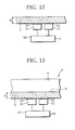
- FIGS. 12 and 13 A schematic diagram of the interface inspection method performed in this example is shown in FIGS. 12 and 13 .
- unfilled bottom steel plate 2 not fill with concrete 4 was prepared.
- a composite slab 6 with the simulated void 9 not formed in the interface 8 was prepared as a comparative example.
- the composite slabs 6 prepared in this example were a composite slab 6 just after filled with fresh concrete 4 and a composite slab 6 left to stand for one hour after being filled with fresh concrete 4.
- a 5-mm-thick gel sheet was used as the contact medium 13.
- the bottom steel plate 2 was equal in thickness D to example 1 described above.
- FIGS. 14A to 14F Results are shown in FIGS. 14A to 14F .
- FIG. 14A is a graph showing flaw detection results produced by performing ultrasonic flaw detection of the bottom steel plate 2 not filled with concrete using a gel sheet as the contact medium 13
- FIG. 14B is a graph showing signal processing results of the flaw detection waveform of FIG. 14A
- FIG. 14C is a graph showing flaw detection results produced by performing ultrasonic flaw detection of the bottom steel plate 2 using a gel sheet as the contact medium 13 just after the bottom steel plate 2 is filled with fresh concrete 4
- FIG. 14D is a graph showing signal processing results of the flaw detection waveform of FIG. 14C
- FIG. 14E is a graph showing flaw detection results produced by performing ultrasonic flaw detection of a bottom steel plate using a gel sheet as a contact medium 60 minutes after the bottom steel plate is filled with fresh concrete
- FIG. 14F is a graph showing signal processing results of the flaw detection waveform of FIG. 14E .
- a bandpass filter (regardless of whether the bandpass filter is analog or digital) or wavelet transform may be applied instead of frequency analysis, where the bandpass filter passes only a specific frequency of a received signal waveform and the wavelet transform is a type of frequency analysis.
- the wavelet transform in particular, is preferable because even after a received signal obtained by ultrasonic flaw detection is converted, time axis information remains in addition to frequency - amplitude characteristics, making it possible to use an analysis method for a sum, product, or the like of any desired components.
- the concrete 4 may be compacted by installing a vibrator or the like at a flaw detection location on the bottom steel plate 2 and then the filled condition of the interface 8 may be inspected again using the interface inspection method described above. This allows a desired location of the interface 8 to be inspected easily. Also, since the condition of the interface 8 can be grasped before the concrete 4 hardens, eliminating the need to make repairs by making a hole in the steel plate after the concrete 4 hardens and filling concrete or the like into the void, it is possible to improve working efficiency.
- the interface inspection method of the present invention has been applied to check the interface 8 of fresh concrete 4, interface 8 of hardened concrete 4', and for trapped water in interface 8, this is not restrictive and the interface inspection method can be applied to check, for example, separation of laminated fiber-glass reinforced plastic layers. Also in cast molding which involves pouring rubber into a mold to cause the rubber to cure, the method can be applied to check the filled condition of an interface between rubber and mold, for example, to check for any cavity produced when the rubber is stagnant.
Landscapes
- Physics & Mathematics (AREA)
- General Physics & Mathematics (AREA)
- Pathology (AREA)
- Life Sciences & Earth Sciences (AREA)
- Chemical & Material Sciences (AREA)
- Analytical Chemistry (AREA)
- Biochemistry (AREA)
- Health & Medical Sciences (AREA)
- Immunology (AREA)
- General Health & Medical Sciences (AREA)
- Engineering & Computer Science (AREA)
- Signal Processing (AREA)
- Acoustics & Sound (AREA)
- Mathematical Physics (AREA)
- Spectroscopy & Molecular Physics (AREA)
- Investigating Or Analyzing Materials By The Use Of Ultrasonic Waves (AREA)
Applications Claiming Priority (3)
| Application Number | Priority Date | Filing Date | Title |
|---|---|---|---|
| JP2012182329 | 2012-08-21 | ||
| JP2012259955 | 2012-11-28 | ||
| PCT/JP2013/072117 WO2014030615A1 (ja) | 2012-08-21 | 2013-08-19 | 複合構造体の界面検査方法及び装置 |
Publications (2)
| Publication Number | Publication Date |
|---|---|
| EP2889613A1 true EP2889613A1 (de) | 2015-07-01 |
| EP2889613A4 EP2889613A4 (de) | 2016-05-04 |
Family
ID=50149924
Family Applications (1)
| Application Number | Title | Priority Date | Filing Date |
|---|---|---|---|
| EP13830901.8A Withdrawn EP2889613A4 (de) | 2012-08-21 | 2013-08-19 | Verfahren und vorrichtung zur inspektion der schnittstelle einer verbundstruktur |
Country Status (3)
| Country | Link |
|---|---|
| EP (1) | EP2889613A4 (de) |
| JP (1) | JP5909285B2 (de) |
| WO (1) | WO2014030615A1 (de) |
Cited By (1)
| Publication number | Priority date | Publication date | Assignee | Title |
|---|---|---|---|---|
| US11193912B2 (en) | 2016-03-01 | 2021-12-07 | Mitsubishi Electric Corporation | Ultrasonic measurement apparatus and ultrasonic measurement method |
Families Citing this family (6)
| Publication number | Priority date | Publication date | Assignee | Title |
|---|---|---|---|---|
| EP3088884A1 (de) * | 2015-04-28 | 2016-11-02 | Uniper Technologies Limited | Verfahren und system zur ultraschallbestimmung des zustands einer gebäudestruktur |
| US10302600B2 (en) | 2016-01-19 | 2019-05-28 | Northrop Grumman Innovation Systems, Inc. | Inspection devices and related systems and methods |
| JP6850185B2 (ja) * | 2017-04-14 | 2021-03-31 | 日立造船株式会社 | 空隙判定方法、空隙判定システム及び弾性波検出方法 |
| JP6971677B2 (ja) * | 2017-07-24 | 2021-11-24 | 株式会社駒井ハルテック | 測定装置及び測定方法 |
| JP2022526837A (ja) * | 2019-04-17 | 2022-05-26 | ディーエムシー グローバル インコーポレイテッド | 多層構造の物品における強固な結合と弱い結合の間の結合境界を特定する方法及びシステム |
| KR102516411B1 (ko) * | 2022-12-27 | 2023-03-31 | 성균관대학교산학협력단 | 지상투과레이더를 활용한 교량상판 내부체수를 계측하는 방법 및 이의 기록매체 |
Family Cites Families (5)
| Publication number | Priority date | Publication date | Assignee | Title |
|---|---|---|---|---|
| SU1158920A1 (ru) * | 1983-08-04 | 1985-05-30 | Петрозаводский государственный университет им.О.В.Куусинена | Устройство дл ультразвукового контрол качества неоднородных бетонных конструкций |
| JPS61254850A (ja) * | 1985-05-07 | 1986-11-12 | Bridgestone Corp | 接着部の非破壊検査方法 |
| JPH04323553A (ja) * | 1991-04-23 | 1992-11-12 | Nippon Steel Corp | 超音波共振探傷方法および装置 |
| JPH08105864A (ja) * | 1994-09-30 | 1996-04-23 | Hihakai Kensa Kk | 弾性波パルスを用いた試験装置及び試験方法 |
| JP3883466B2 (ja) | 2001-10-29 | 2007-02-21 | 曙ブレーキ工業株式会社 | 充填物検知方法及び充填物検知装置 |
-
2013
- 2013-08-19 EP EP13830901.8A patent/EP2889613A4/de not_active Withdrawn
- 2013-08-19 WO PCT/JP2013/072117 patent/WO2014030615A1/ja not_active Ceased
- 2013-08-19 JP JP2014531620A patent/JP5909285B2/ja not_active Expired - Fee Related
Cited By (1)
| Publication number | Priority date | Publication date | Assignee | Title |
|---|---|---|---|---|
| US11193912B2 (en) | 2016-03-01 | 2021-12-07 | Mitsubishi Electric Corporation | Ultrasonic measurement apparatus and ultrasonic measurement method |
Also Published As
| Publication number | Publication date |
|---|---|
| JPWO2014030615A1 (ja) | 2016-07-28 |
| JP5909285B2 (ja) | 2016-04-26 |
| EP2889613A4 (de) | 2016-05-04 |
| WO2014030615A1 (ja) | 2014-02-27 |
Similar Documents
| Publication | Publication Date | Title |
|---|---|---|
| EP2889613A1 (de) | Verfahren und vorrichtung zur inspektion der schnittstelle einer verbundstruktur | |
| US6962082B2 (en) | Device and method for acoustic diagnosis and measurement by pulse electromagnetic force | |
| Rucka et al. | Experimental study on ultrasonic monitoring of splitting failure in reinforced concrete | |
| KR102260598B1 (ko) | 비접촉 초음파를 활용한 아스팔트-콘크리트 교면 박리손상 평가 시스템 및 그 방법 | |
| US20040123665A1 (en) | Nondestructive detection of reinforcing member degradation | |
| US5095465A (en) | In situ testing with surface seismic waves of materials having properties that change with time | |
| US20080236285A1 (en) | Device for measuring bulk stress via insonification and method of use therefor | |
| Sun et al. | Application of low-profile piezoceramic transducers for health monitoring of concrete structures | |
| Stepinski | Novel instrument for inspecting rock bolt integrity using ultrasonic guided waves | |
| CN106840477B (zh) | 一种长期监测psc结构预应力损失的装置及方法 | |
| CN118960861B (zh) | 既有结构预应力与孔道内缺陷全息联合监测方法与装置 | |
| CN106932485A (zh) | 一种基于压电智能骨料的预应力筋锈蚀深度监测方法 | |
| US20150153313A1 (en) | Interface inspection method and apparatus for composite structure | |
| CN106226506A (zh) | 检测预应力混凝土结构锈胀裂缝的系统及骨料制作方法 | |
| JP3198840U (ja) | 支柱路面境界部調査システム | |
| JP6684575B2 (ja) | 合成コンクリート構造物の検査方法、健全性評価方法、及び検査結果表示システム | |
| KR101154587B1 (ko) | 압전센서를 이용한 임피던스 및 유도초음파 기반의 배관구조물 모니터링 시스템 | |
| JP2005148061A (ja) | 共振分析を使用した超音波探知装置及び超音波探知方法 | |
| Park et al. | Damage diagnostics on a welded zone of a steel truss member using an active sensing network system | |
| CN116907710B (zh) | 一种基于超声波反射系数的钢绞线锚下应力测量方法 | |
| Kumar et al. | Structural integrity assessment of the containment structure of a pressurised heavy water nuclear reactor using impact echo technique | |
| JP5517374B1 (ja) | 複合構造体の界面検査方法、界面検査装置、及び界面検査プログラム | |
| Bartoli et al. | Nonlinear ultrasonic guided waves for stress monitoring in prestressing tendons for post-tensioned concrete structures | |
| JPH0768763B2 (ja) | コンクリート構造物の充填グラウトの介装状態検出方法及び装置 | |
| Abbasi et al. | The quantification of errors in the measurement of nonlinear ultrasonics |
Legal Events
| Date | Code | Title | Description |
|---|---|---|---|
| PUAI | Public reference made under article 153(3) epc to a published international application that has entered the european phase |
Free format text: ORIGINAL CODE: 0009012 |
|
| 17P | Request for examination filed |
Effective date: 20150220 |
|
| AK | Designated contracting states |
Kind code of ref document: A1 Designated state(s): AL AT BE BG CH CY CZ DE DK EE ES FI FR GB GR HR HU IE IS IT LI LT LU LV MC MK MT NL NO PL PT RO RS SE SI SK SM TR |
|
| AX | Request for extension of the european patent |
Extension state: BA ME |
|
| DAX | Request for extension of the european patent (deleted) | ||
| RA4 | Supplementary search report drawn up and despatched (corrected) |
Effective date: 20160405 |
|
| RIC1 | Information provided on ipc code assigned before grant |
Ipc: G01N 29/44 20060101ALI20160330BHEP Ipc: G01N 29/11 20060101ALI20160330BHEP Ipc: G01N 29/04 20060101AFI20160330BHEP Ipc: G01N 29/46 20060101ALI20160330BHEP Ipc: G01N 29/34 20060101ALI20160330BHEP |
|
| 17Q | First examination report despatched |
Effective date: 20181109 |
|
| STAA | Information on the status of an ep patent application or granted ep patent |
Free format text: STATUS: THE APPLICATION HAS BEEN WITHDRAWN |
|
| 18W | Application withdrawn |
Effective date: 20190204 |