EP2889237B1 - Transportleitungsabdeckung - Google Patents
Transportleitungsabdeckung Download PDFInfo
- Publication number
- EP2889237B1 EP2889237B1 EP14004099.9A EP14004099A EP2889237B1 EP 2889237 B1 EP2889237 B1 EP 2889237B1 EP 14004099 A EP14004099 A EP 14004099A EP 2889237 B1 EP2889237 B1 EP 2889237B1
- Authority
- EP
- European Patent Office
- Prior art keywords
- transport line
- transport
- sample
- groove
- cover
- Prior art date
- Legal status (The legal status is an assumption and is not a legal conclusion. Google has not performed a legal analysis and makes no representation as to the accuracy of the status listed.)
- Active
Links
Images

Classifications
-
- G—PHYSICS
- G01—MEASURING; TESTING
- G01N—INVESTIGATING OR ANALYSING MATERIALS BY DETERMINING THEIR CHEMICAL OR PHYSICAL PROPERTIES
- G01N35/00—Automatic analysis not limited to methods or materials provided for in any single one of groups G01N1/00 - G01N33/00; Handling materials therefor
- G01N35/02—Automatic analysis not limited to methods or materials provided for in any single one of groups G01N1/00 - G01N33/00; Handling materials therefor using a plurality of sample containers moved by a conveyor system past one or more treatment or analysis stations
- G01N35/04—Details of the conveyor system
-
- B—PERFORMING OPERATIONS; TRANSPORTING
- B65—CONVEYING; PACKING; STORING; HANDLING THIN OR FILAMENTARY MATERIAL
- B65G—TRANSPORT OR STORAGE DEVICES, e.g. CONVEYORS FOR LOADING OR TIPPING, SHOP CONVEYOR SYSTEMS OR PNEUMATIC TUBE CONVEYORS
- B65G21/00—Supporting or protective framework or housings for endless load-carriers or traction elements of belt or chain conveyors
- B65G21/08—Protective roofs or arch supports therefor
-
- G—PHYSICS
- G01—MEASURING; TESTING
- G01N—INVESTIGATING OR ANALYSING MATERIALS BY DETERMINING THEIR CHEMICAL OR PHYSICAL PROPERTIES
- G01N35/00—Automatic analysis not limited to methods or materials provided for in any single one of groups G01N1/00 - G01N33/00; Handling materials therefor
- G01N2035/00178—Special arrangements of analysers
- G01N2035/00277—Special precautions to avoid contamination (e.g. enclosures, glove- boxes, sealed sample carriers, disposal of contaminated material)
- G01N2035/00287—Special precautions to avoid contamination (e.g. enclosures, glove- boxes, sealed sample carriers, disposal of contaminated material) movable lid/cover for sample or reaction tubes
-
- G—PHYSICS
- G01—MEASURING; TESTING
- G01N—INVESTIGATING OR ANALYSING MATERIALS BY DETERMINING THEIR CHEMICAL OR PHYSICAL PROPERTIES
- G01N35/00—Automatic analysis not limited to methods or materials provided for in any single one of groups G01N1/00 - G01N33/00; Handling materials therefor
- G01N2035/00178—Special arrangements of analysers
- G01N2035/00326—Analysers with modular structure
-
- G—PHYSICS
- G01—MEASURING; TESTING
- G01N—INVESTIGATING OR ANALYSING MATERIALS BY DETERMINING THEIR CHEMICAL OR PHYSICAL PROPERTIES
- G01N35/00—Automatic analysis not limited to methods or materials provided for in any single one of groups G01N1/00 - G01N33/00; Handling materials therefor
- G01N35/02—Automatic analysis not limited to methods or materials provided for in any single one of groups G01N1/00 - G01N33/00; Handling materials therefor using a plurality of sample containers moved by a conveyor system past one or more treatment or analysis stations
- G01N35/04—Details of the conveyor system
- G01N2035/046—General conveyor features
- G01N2035/0467—Switching points ("aiguillages")
Definitions
- the present invention relates to a cover that covers an opening at the top of a sample transport apparatus that is suited to transporting samples between a plurality of sample inspection apparatuses (hereinafter also referred to as a "transport line cover").
- sample inspection apparatuses include sample processing apparatuses, biochemical analyzers, immunoassay apparatuses, and sample accommodating apparatuses.
- sample inspection apparatuses include not only single-module apparatuses but also apparatuses that are obtained by combining a plurality of modules.
- a layout for installing a sample inspection apparatus or a sample transport apparatus may vary depending on the installation place or needs of customers.
- sample transport apparatuses are now often customized in accordance with the installation place or the like, it has become more difficult to use common component parts.
- common transport line covers for avoiding entry of dust or dirt.
- a typical sample transport apparatus has two transport lines that are arranged in parallel in the long-side direction thereof, but a transport line cover that is necessary therefor has a too large horizontal width for an operator to grasp with one hand. Therefore, the operator usually grasps the transport line cover with two hands to perform an operation of attaching or detaching the cover. However, when workability is considered, it would be desirable that the transport line cover be grasped with one hand.
- a transport line cover that includes a (1) cover body adapted to cover an opening at a top of a sample transport apparatus, the sample transport apparatus accommodating a plurality of transport lines that extend in one direction; and (2) a first groove formed on an upper face of the cover body, the first groove extending from one short side to another short side of the cover body. A lower end of a long-side side face of the cover body is located at a level below a bottom face of the first groove.
- FIG. 1 shows an exemplary appearance structure of a sample inspection system.
- the sample inspection system herein is an exemplary system that has a plurality of sample inspection apparatuses connected together with dedicated transport channels (i.e., sample transport apparatuses).
- the scale of the sample inspection system and the combination of sample inspection apparatuses that constitute the system may differ in accordance with the installation place or needs of customers.
- a sample refers to a target to be inspected that is egested or taken from a human body, and includes, for example, blood, urine, feces, tissues, and cells.
- the sample inspection system shown in FIG. 1 includes a sample processing apparatus 100, a sample analyzer (i.e., biochemical analyzer) 110, a sample analyzer (i.e., an apparatus obtained by connecting a biochemical analyzer and an immunoassay apparatus) 120, a sample accommodating apparatus (i.e., refrigerator) 130, five sample transport apparatuses 140, and two sample transport apparatuses 150 for connection.
- a sample processing apparatus 100 e.e., a sample analyzer 110
- a sample analyzer i.e., an apparatus obtained by connecting a biochemical analyzer and an immunoassay apparatus
- a sample accommodating apparatus i.e., refrigerator
- the inspection processing apparatus 100 in this embodiment includes, for example, a loading module for installing a loaded sample onto an inspection rack (hereinafter referred to as a "sample holder"), a storage module for taking out the sample from the sample holder, a processing module (e.g., an centrifugal module, an uncapping module, a dispensing module, a barcode sticking module, or a sample classification module) for executing a predetermined process on the sample and/or the sample holder, a rack stocker for supplying and collecting sample holders, and a control unit (not shown).
- the sample processing apparatus 100 has extended main transport lines, each of which transports sample holders each holding at least one sample in the long-side direction, such that the main transport line crosses the module.
- main transport lines are arranged in two stages including upper and lower stages. In each stage, two main transport lines that transport samples in opposite directions are arranged in parallel. It should be noted that the main transport lines on the lower stage side are adapted to transport empty sample holders from which samples have been taken out. Needless to say, the main transport lines may also be arranged in a single stage or three or more stages. The specifications, such as the dimensions, mounting positions, and mounting heights of the main transport lines are made common to all apparatuses that constitute the sample inspection system (in the case of FIG. 1 , the sample analyzer 110, the sample analyzer 120, the sample accommodating apparatus 130, the sample transport apparatuses 140, and the sample transport apparatuses 150 for junction).
- sample analyzer 110 is a stand-alone biochemical analyzer
- sample analyzer 120 is an apparatus obtained by connecting a biochemical apparatus and an immunoassay apparatus in series in the transport direction
- sample accommodating apparatus 130 is a large-tower-type accommodating apparatus used for refrigeration storage of samples.
- the sample transport apparatus 140 is a specialized transport apparatus for transporting samples and/or sample holders in the long-side direction, and basically has no other functional portions than the transport function.
- the sample transport apparatus 140 includes in its housing the aforementioned main transport lines, a drive mechanism (which includes a belt conveyor and its driving motor) for moving sample holders along the main transport lines, a power supply unit that supplies power to at least the motor and the like of the drive mechanism, and wires such as power lines and control signal lines.
- FIG. 2 shows an exemplary appearance of the sample transport apparatus 140.
- the sample transport apparatus 140 is connected in a T-shape via the sample transport apparatus 150 for junction.
- the sample transport apparatus 140 shown in FIG. 2 accommodates transport lines that extend in the long-side direction, a pair of right and left housings (panels) 141 forming the long-side side faces, a transport line cover 142 that covers an opening at the top of the housings, a base substrate 143 that supports the housings 141 and an internal structure (not shown), openable/closable doors 144 forming the long-side side faces of the sample transport apparatus 140 together with the housings 141, and legs 145 attached to the bottom of the base substrate 143.
- the sample transport apparatus 140 is based on the premise that it will be connected to another sample transport apparatus or a sample inspection apparatus, and thus has open opposite ends in the long-side direction. That is, the sample transport apparatus 140 has an appearance whose cross section is approximately rectangular in shape.
- one of two types of units that have common component parts other than the transport line length (that is, the length of the housing in the long-side direction) is used for the sample transport apparatus 140.
- the transport line length is supposed to be 600 mm or 900 mm.
- the sample transport apparatus 150 for junction is a transport-only apparatus that can connect to the sample transport apparatus 140 and/or the sample inspection apparatus in a plurality of directions. Therefore, as with the sample transport apparatus 140, the sample transport apparatus 150 for junction basically has no other functions than the transport function.
- the sample transport apparatus 150 for junction includes main transport lines, a drive mechanism (which includes a belt conveyor and its driving motor) that moves sample holders along the main transport lines, a power supply unit that supplies power to at least the motor and the like of the drive mechanism, and wires such as power lines and control signal lines.
- the sample transport apparatus 150 for junction has, in addition to the transport mechanism for taking in and out sample holders to/from the sample transport apparatus 140 or a sample inspection apparatus, which is connected in series with the sample transport apparatus 150 for junction in the long-side direction, a transport mechanism for taking in and out sample holders to/from the sample transport apparatus 140 connected at a predetermined mounting angle, sub-transport lines for transferring sample holders from one of the pair of main transport lines arranged in parallel to the other main transport line, a stopper used to individually switch the transport directions of sample holders at a plurality of branch points in the transport direction, and a direction changing mechanism.
- the sample transport apparatus 150 for junction comes in various shapes, for example, those for T-shape connection, L-shape connection, and Y-shape connection.
- the sample transport apparatus 150 for junction shown in FIG. 2 is the apparatus for T-shape connection. It should be noted that when transport to one of the sample transport apparatuses 140 that extend rightward and leftward from the long-side side faces of the sample transport apparatus 150 for junction is not necessary, the sample transport apparatus 150 for junction for L-shape connection is used.
- sample transport apparatus 150 for junction for T-shape connection can also be used as a sample transport apparatus 150 for junction for L-shape connection as long as one of the two openings formed on the respective long-side side faces of the sample transport apparatus 150 for junction for T-shape connection is covered.
- the sample transport apparatus 150 for junction includes a rectangular housing 151 for accommodating main-transport lines that extend in the long-side direction and sub-transport lines that extend in the short-side direction, and a transport line cover 152 that covers an opening at the top of the housing.
- the housing 151 of the sample transport apparatus 150 for junction is a box-shaped housing whose bottom face is near a floor surface (i.e., installation surface), and has four height adjustment legs 153 at the bottom face.
- the transport line cover 152 is assumed to be detachably mounted on the opening at the top. With the detachable transport line cover 152, it is possible to directly perform maintenance of the transport lines only by removing the transport line cover 152. Needless to say, the transport line cover 152 may also be integrally fixed to the opening at the top of the sample transport apparatus 150 for junction. Hereinafter, description will be made of a case where the transport line cover 152 is detachably mountable on the opening at the top.
- the sample transport apparatus 150 for junction for T-shape connection is connected to other sample transport apparatuses 140 only on the two long-side side faces and one short-side side face as described with reference to Fig. 2 . That is, it is unnecessary to consider connection of the remaining short-side side face to another sample transport apparatus 140. Therefore, a structure for avoiding entry of dust or dirt into the sample transport apparatus 150 for junction from the outside is adopted for the short-side side face to which another sample transport apparatus 140 need not be connected.
- FIGS. 3A and 3B each show an exemplary structure of the transport line cover 152.
- the transport line cover 152 includes a cover body 161 and an end cap 162 that is attached to an opening at one end (i.e., on a short-side side face) of the cover.
- the transport line cover 152 is designed in accordance with the dimensions of an opening at the top of the sample transport apparatus 150 for junction.
- FIG. 3B shows exemplary dimensions that are suitable for the transport line cover 152 of a 600 mm type. In the case of FIG. 3B , the length of the transport line cover 152 in the long-side direction is 573 mm.
- the length of the cover body 161 in the long-side direction is 543 mm
- the length of the end cap 162 in the same direction is 30 mm
- the length of the transport line cover 152 in the short-side direction is 248 mm
- the height thereof is 50 mm.
- each of the cover body 161 and the end cap 162 has formed thereon a linear groove 163 that extends from one short side to the other short side of the transport line cover 152.
- Such groove 163 has a shape and position that allow an operator to easily grasp the transport line cover 152 with one hand.
- the groove 163 is formed at a position where both the groove 163 and one long-side side face of the cover body 161 can be grasped with one hand.
- the groove 163 is formed such that it passes through the center position of the transport line cover 152 in the short-side direction. Therefore, an operator is able to grasp the long-side side face on either the right side or the left side with respect to the groove 163.
- the groove 163 is integrally formed such that it penetrates up to the opposite ends of the transport line cover 152 (i.e., across the entire region of from the cover body 161 up to an end of the end cap 162), it is possible to easily sweep dust and dirt, which have accumulated in the groove 163, away from both ends of the transport line cover 152.
- the groove 163 also has the effect of increasing the rigidity of the transport line cover 152.
- the groove 163 in this embodiment is formed in a shape that allows at least the first joint of a finger to be inserted into the groove 163 from above the transport line cover 152.
- the length (width) of the groove 163 in the short-side direction is 30 mm, and the depth thereof from the upper face is 20 mm.
- the cross-sectional shape of the groove 163 may be any shape, for example, a rectangular shape, a U-shape, or a semicircular shape.
- FIG. 3B shows an example in which the cross-sectional shape of the groove 163 is a U-shape.
- the groove 163 When the groove 163 has a U-shaped cross-section, the groove 163 is formed by two upper inner wall portions that are opposite each other and one lower, curved inner wall portion that forms a bottom face. In the case of FIG. 3B , the height of each upper inner wall portion is 5 mm, and the lower, curved inner wall portion is formed along a semicircle with a radius of 15 mm.
- each upper inner wall portion of the groove 163 is formed at right angles to the upper faces of the cover body 161 and the end cap 162.
- a connection portion between the upper face and the long-side side face of each of the cover body 161 and the end cap 162 can also be formed in a similar shape.
- the connection portion between the upper face and the long-side side face is formed such that the cross-sectional shape thereof is along a curved surface with a radius of 30 mm.
- the radius that defines the connection portion is not limited to a constant value, and the radius of the curved face may continuously change along the direction from the side of the groove 163 toward the long-side side face.
- a tilt angle that is formed between each upper inner wall of the groove 163 and the upper face is formed to be greater than a tilt angle that is formed at the connection portion between the upper face and the long-side side face of the cover body 161.
- the angle of an edge portion (i.e., point P1) between the groove 163 and the upper face of the transport line cover 152 is a right angle
- the tilt angle of a connection portion (i.e., point P2) between the upper face and the long-side side face of the transport line cover 152 is gentle. That is, the angle of the point P2 is more gentle than the angle of the point P1.
- FIGS. 3A, 3B and 4 each show an example in which the transport line cover 152 has a flat upper face, the transport line cover 152 may also have a dome-like cross-sectional shape or a hog-backed cross-sectional shape.
- At least the cover body 161 of the transport line cover 152 in this embodiment is formed with a resin material (i.e., transparent resin).
- a resin material i.e., transparent resin
- two cutouts 164 are formed on a side face of the cover body 161.
- Such cutouts 164 are provided corresponding to the mounting positions of transport lines in the sample transport apparatus 140 connected from the lateral side.
- the transport line cover 152 for T-shape connection has two cutouts 164 on each of the two long-side side faces.
- the transport line cover 152 for L-shape connection has two cutouts 164 only on one of the two long-side side faces to which another apparatus is connected.
- each cutout 164 has dimensions: a length of 50 mm and a height of 12 mm.
- the cover body 161 has the end cap 162 attached to an opening at one end of the cover body 161.
- the end cap 162 is attached such that it is embedded into the opening at one end of the body cap 161.
- the end cap 162 may be either removable from the cover body 161 or be unremovabley secured to the cover body 161.
- the transport line cover 142 is also assumed to be detachably mounted on the opening at the top.
- the transport line cover 142 may also be integrally fixed to the opening at the top of the sample transport apparatus 140.
- description will be made of a case where the transport line cover 142 is detachably mountable on the opening at the top.
- FIGS. 5A and 5B each show an exemplary structure of the transport line cover 142 with an end cap. That is, FIGS. 5A and 5B each show an exemplary structure of the transport line cover 142 that is preferably used at a portion where the sample transport apparatus 140 is connected to the sample transport apparatus 150 for junction.
- the transport line cover 142 includes a cover body 171 and an end cap 172 that is attached to an opening at one end (i.e., on a short-side side face) of the cover.
- the transport line cover 142 is designed in accordance with the dimensions of an opening at the top of the sample transport apparatus 140.
- Fig. 5B shows exemplary dimensions that are suitable for the transport line cover 142 of a 600 mm type. In the case of FIG.
- the length of the transport line cover 142 in the long-side direction is 573 mm.
- the length of the main cover 171 in the long-side direction is 543 mm, and the length of the end cap 172 in the same direction is 30 mm.
- the length of the transport line cover 142 in the short-side direction is 248 mm, and the height thereof is 50 mm. It should be noted that in the case of the transport line cover 142 of the sample transport apparatus 140 that has no portion connected to the sample transport apparatus 150 for junction, the end cap 172 is not necessary. Thus, in such a case, the length of the cover body 171 in the long-side direction is 573 mm.
- the transport line cover 142 also has a linear groove 173, which extends from one short side to the other short side of the transport line cover 142, formed on the upper faces of the cover body 171 and the end cap 172.
- the purpose of forming the groove 173, the dimensions thereof, and the like are similar to those of the aforementioned transport line cover 152. Thus, detailed description thereof is omitted herein.
- the structure of the end cap 172 that is specific to the transport line cover 142 will be described.
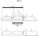
- the end cap 172 has formed therein an upper-stage portion 175 with a length of 20 mm in the long-side direction of the transport line cover 142, and a lower-stage portion 176 that further protrudes beyond the upper-stage portion 175 in the long-side direction by 10 mm. It should be noted that the amount of protrusion of the lower-stage portion 176 is determined so as to provide sufficient dimensions to allow a fingertip to be inserted to grasp the transport line cover 152 that is attached to the sample transport apparatus 150 for junction.
- the end cap 172 When the end cap 172 is used, it is possible to, as shown in the upper view of FIG. 6 , secure enough space for a fingertip to be inserted between the end cap 172 and the long-side side face of the transport line cover 152 by the amount of protrusion of the lower-stage portion 176, so that the transport line cover 152 can be grasped with one hand even at a portion where the sample transport apparatus 150 for junction is connected to the sample transport apparatus 140.
- the end cap 172 has no lower-stage portion, it would be impossible to, as shown in the lower view of FIG.
- the height of the lower-stage portion 176 in this embodiment is 20 mm. It should be noted that the height of the lower-stage portion 176 is not limited to 20 mm as long as it is lower than the height of the bottom of the groove 173. In this embodiment, the height of the bottom of the groove 173 is 30 mm in the upward direction from the lower face of the end cap 172 (or 20 mm in the downward direction from the upper face). Thus, it is acceptable as long as the height of the lower-stage portion 176 is less than 30 mm. Needless to say, as the height of the lower-stage portion 176 is greater, the space for inserting a finger becomes narrower, with the result that the transport line cover 152 becomes difficult to grasp. Thus, the height of the lower-stage portion 176 is desirably as low as possible.
- the lower limit of the height of the lower-stage portion 176 is restricted by the heights of the cutouts 174.
- the cutouts 174 need not be provided.
- the grooves 163 and 173 are formed on the upper faces of the transport line covers 152 and 142, respectively, such that the grooves extend from one short sides to the other short sides of the respective covers.
- a tilt angle that is an angle between the upper face of the transport line cover 142 or 152 and the groove 173 or 163 is formed to be greater than a tilt angle that is an angle between the upper face and the long-side side face of the transport line cover 142 or 152, it becomes possible to more easily remove each of the transport line covers 142 and 152 outwardly from the sample transport space. Consequently, the risk that the transport line cover 142 or 152 may fall in the transport space during an operation of removing the cover can be reduced.
- grooves 163 and 173 are formed such that they include the center positions of the transport line covers 152 and 142 in the short-side directions, respectively, it is possible to allow the transport line covers 142 and 152 to be grasped either on the right side or the left side with respect to the grooves 173 and 163, respectively.
- the end cap 172 of the transport line cover 142 which is used at least at a portion where the sample transport apparatus 140 is connected to the sample transport apparatus 150 for junction, is provided with the lower-stage portion 176, and the amount of protrusion of the lower-stage portion 176 is made greater than at least the length that allows a fingertip to be inserted.
- the transport line cover 152 it is possible to allow the transport line cover 152 to be grasped with one hand even at a portion where the sample transport apparatus 140 is connected to the sample transport apparatus 150 for junction.
- the present invention is not limited to the structures of the aforementioned embodiments, and includes a variety of variations, within the scope of the claims.
Landscapes
- Engineering & Computer Science (AREA)
- Mechanical Engineering (AREA)
- Physics & Mathematics (AREA)
- Health & Medical Sciences (AREA)
- Life Sciences & Earth Sciences (AREA)
- Chemical & Material Sciences (AREA)
- Analytical Chemistry (AREA)
- Biochemistry (AREA)
- General Health & Medical Sciences (AREA)
- General Physics & Mathematics (AREA)
- Immunology (AREA)
- Pathology (AREA)
- Automatic Analysis And Handling Materials Therefor (AREA)
- Sampling And Sample Adjustment (AREA)
Claims (9)
- Transportlinienabdeckung umfassend:einen Abdeckungskörper (161, 171) zum Abdecken einer Öffnung oben an einer Probentransportvorrichtung, die mehrere in eine Richtung verlaufende Transportlinien enthält, wobei der Abdeckungskörper lange und kurze Seiten aufweist und auf seiner langen Seite eine längsseitige Seitenfläche aufweist,dadurch gekennzeichnet, dassauf einer oberen Fläche des Abdeckungskörper eine erste Rille (163, 173) ausgebildet ist, die sich von einer kurzen Seite zu einer anderen kurzen Seite des Abdeckungskörpers erstreckt und an einem Ort ausgebildet ist, an dem sowohl die erste Rille als auch eine längsseitige Seitenfläche des Abdeckungskörpers (161, 171) mit einer Hand gegriffen werden können,die erste Rille (163, 173) in einer Form ausgebildet ist, die es erlaubt, dass zumindest das erste Glied eines Fingers von oberhalb der Transportlinienabdeckung in die erste Rille eingeführt werden kann,ein unteres Ende der längsseitigen Seitenfläche des Abdeckungskörpers auf einer Höhe unterhalb einer Bodenfläche der ersten Rille angeordnet ist, undein Kippwinkel zwischen der oberen Fläche des Abdeckungskörpers und der oberen Innenwand der ersten Rille größer als ein Kippwinkel zwischen der oberen Fläche und der längsseitigen Seitenfläche des Abdeckungskörpers ist.
- Transportlinienabdeckung nach Anspruch 1, wobei die erste Rille (163, 173) eine rechteckige, eine U-förmige oder eine halbkreisförmige Querschnittsform aufweist.
- Transportlinienabdeckung nach Anspruch 1 oder 2, wobei der Abdeckungskörper (161, 171) von der Öffnung oben an der Probentransportvorrichtung abnehmbar und an ihr anbringbar ist.
- Transportlinienabdeckung nach einem der Ansprüche 1 bis 3, wobei der Abdeckungskörper (161, 171) aus einem transparenten Element gebildet ist.
- Transportlinienabdeckung nach einem der Ansprüche 1 bis 4, wobei die erste Rille (161, 173) in kurzseitiger Richtung einen Mittelort des Abdeckungskörpers (161, 171) enthält.
- Transportlinienabdeckung nach einem der Ansprüche 1 bis 5, mit einer Endkappe (162, 172), die an einer der einander gegenüber liegenden Enden in längsseitiger Richtung des Abdeckungskörpers (161, 171) anbringbar ist, wobeieine obere Fläche der Endkappe eine darauf ausgebildete zweite Rille (163, 173) aufweist, die sich von einer kurzen Seite zu einer anderen kurzen Seite der Endkappe erstreckt, unddie zweite Rille dann, wenn die Endkappe am Abdeckungskörper angebracht ist, unmittelbar mit der ersten Rille (163, 173) verbunden ist.
- Transportlinienabdeckung nach Anspruch 6, wobei die Endkappe (162, 172) so angebracht ist, dass sie in eine Öffnung an einem Ende der Transportlinienabdeckung eingebettet ist.
- Transportlinienabdeckung nach Anspruch 6 oder 7, wobei die Endkappe (172), die auf einer Seite in Kontakt mit einer längsseitigen Seitenfläche einer anderen Transportlinienabdeckung angeordnet ist, einen abgestuften Abschnitt (176) aufweist, der in längsseitiger Richtung des Abdeckungskörpers (161, 171) über einen hochgestuften Abschnitt (175) hinausgeht, in dem die zweite Rille ausgebildet ist.
- Transportlinienabdeckung nach Anspruch 8, wobei der abgestufte Abschnitt (176) mindestens in einem solchen Maß hinausgeht, dass eine Fingerspitze zum Greifen der anderen Transportlinienabdeckung eingeführt werden kann.
Applications Claiming Priority (1)
| Application Number | Priority Date | Filing Date | Title |
|---|---|---|---|
| JP2013264575A JP6312421B2 (ja) | 2013-12-20 | 2013-12-20 | 搬送ライン用カバー |
Publications (2)
| Publication Number | Publication Date |
|---|---|
| EP2889237A1 EP2889237A1 (de) | 2015-07-01 |
| EP2889237B1 true EP2889237B1 (de) | 2019-04-17 |
Family
ID=52016366
Family Applications (1)
| Application Number | Title | Priority Date | Filing Date |
|---|---|---|---|
| EP14004099.9A Active EP2889237B1 (de) | 2013-12-20 | 2014-12-04 | Transportleitungsabdeckung |
Country Status (4)
| Country | Link |
|---|---|
| US (1) | US9709585B2 (de) |
| EP (1) | EP2889237B1 (de) |
| JP (1) | JP6312421B2 (de) |
| CN (1) | CN104724458B (de) |
Families Citing this family (1)
| Publication number | Priority date | Publication date | Assignee | Title |
|---|---|---|---|---|
| CN109477873A (zh) * | 2016-07-21 | 2019-03-15 | 西门子医疗保健诊断公司 | 用于ivd自动化系统的磁屏蔽 |
Family Cites Families (24)
| Publication number | Priority date | Publication date | Assignee | Title |
|---|---|---|---|---|
| JPS5571951A (en) * | 1978-11-24 | 1980-05-30 | Toshiba Corp | Automatic chemical analyzer |
| JPS58106313U (ja) * | 1982-01-14 | 1983-07-20 | 住友金属工業株式会社 | ベルトコンベア |
| JPS63155203U (de) * | 1987-03-31 | 1988-10-12 | ||
| JPH01148966A (ja) * | 1987-12-04 | 1989-06-12 | Hitachi Kiden Kogyo Ltd | 検体搬送装置 |
| JPH03110272A (ja) * | 1989-09-26 | 1991-05-10 | Nippon Hantaa Dagurasu Kk | 形パネルの端末処理構造 |
| US5161678A (en) * | 1991-08-19 | 1992-11-10 | Garvey Corporation | Accumulator cover |
| US5947266A (en) * | 1992-11-06 | 1999-09-07 | Rionde Sa | Protective and insulating enclosure with removable panels for a transfer unit |
| US5941366A (en) * | 1996-09-19 | 1999-08-24 | Labotix Automation, Inc. | Transport system for biospecimens |
| WO1998018009A1 (en) * | 1996-10-23 | 1998-04-30 | Hitachi, Ltd. | Biochemical analyzer |
| JP3054684U (ja) * | 1998-06-05 | 1998-12-08 | 株式会社村田商会 | ベルトコンベヤカバー |
| JP4324288B2 (ja) * | 1999-09-29 | 2009-09-02 | 株式会社日立製作所 | 検体搬送装置 |
| US20020053529A1 (en) * | 2000-11-03 | 2002-05-09 | White Thomas M. | File storage container |
| JP3933973B2 (ja) | 2002-03-28 | 2007-06-20 | コクヨ株式会社 | パネル接続構造 |
| CN1312017C (zh) * | 2002-10-30 | 2007-04-25 | 邓耀辉 | 水平输送生产设备 |
| US7357271B2 (en) * | 2004-02-17 | 2008-04-15 | Tegrant Diversified Brands, Inc. | Insulated container with access door |
| WO2006029482A1 (en) * | 2004-09-14 | 2006-03-23 | Myriam Schepers | Inspection hatch for a conveyor belt tunnel |
| JP3976762B2 (ja) * | 2004-12-28 | 2007-09-19 | ヨシコン株式会社 | 側溝ブロック |
| CA2676566C (en) * | 2007-01-26 | 2012-08-21 | Provo Craft And Novelty, Inc. | Cutting apparatus |
| CN201385887Y (zh) * | 2009-04-23 | 2010-01-20 | 王魏 | 一种带有易开启盖子的饼干桶 |
| EP2485058B1 (de) | 2009-09-30 | 2019-07-03 | Hitachi High-Technologies Corporation | Automatisiertes probentestsystem |
| JP5372883B2 (ja) * | 2010-09-30 | 2013-12-18 | 株式会社日立ハイテクノロジーズ | 検体処理システム |
| CN202518748U (zh) * | 2012-04-24 | 2012-11-07 | 广州大台农饲料有限公司 | 一种改进的斗式提升机头罩 |
| CN203173313U (zh) * | 2013-03-12 | 2013-09-04 | 颜旭华 | 水泥生产线用皮带输送机 |
| CN203154099U (zh) * | 2013-04-09 | 2013-08-28 | 徐国兴 | 旅行医疗箱 |
-
2013
- 2013-12-20 JP JP2013264575A patent/JP6312421B2/ja active Active
-
2014
- 2014-12-04 EP EP14004099.9A patent/EP2889237B1/de active Active
- 2014-12-18 CN CN201410795897.1A patent/CN104724458B/zh active Active
- 2014-12-19 US US14/577,379 patent/US9709585B2/en active Active
Non-Patent Citations (1)
| Title |
|---|
| None * |
Also Published As
| Publication number | Publication date |
|---|---|
| CN104724458B (zh) | 2017-06-06 |
| JP6312421B2 (ja) | 2018-04-18 |
| CN104724458A (zh) | 2015-06-24 |
| US9709585B2 (en) | 2017-07-18 |
| EP2889237A1 (de) | 2015-07-01 |
| JP2015121438A (ja) | 2015-07-02 |
| US20150175316A1 (en) | 2015-06-25 |
Similar Documents
| Publication | Publication Date | Title |
|---|---|---|
| EP2889236B1 (de) | Probentransportvorrichtung | |
| US10605819B2 (en) | Transport device having a tiled driving surface | |
| US10948508B2 (en) | Transport device unit for a laboratory sample distribution system | |
| US8361387B2 (en) | System and method for the processing of liquid samples | |
| EP2306504A1 (de) | Haltekörper und substratlagerbehälter | |
| US12320820B2 (en) | Sample pretreatment device, analysis system including the device, and autosampler | |
| KR100847465B1 (ko) | 웨이퍼 케이스의 운용 방법, 웨이퍼 케이스의 반송 방법 및웨이퍼 케이스 반송용 유지 부품 | |
| JP2025016773A (ja) | 容量式流体レベル検出および取扱い容器のためのシステムおよび方法 | |
| WO1998018009A1 (en) | Biochemical analyzer | |
| EP1767272B1 (de) | Halter für Kuvetten, Kuvettenmatrix und Analysevorrichtung mit diesen Komponenten | |
| CN104024758A (zh) | 空气调节机 | |
| EP3206035B1 (de) | Automatisches analysesystem | |
| EP2889237B1 (de) | Transportleitungsabdeckung | |
| JP5212975B2 (ja) | 分析装置用サンプラおよび分析装置 | |
| US9505002B2 (en) | Incubator | |
| WO2011141966A1 (ja) | 移載装置 | |
| US20050036857A1 (en) | Automatic material handling system and stocker therefor | |
| WO2018221220A1 (ja) | 自動分析装置 | |
| JP2017156344A (ja) | ラボラトリ診断容器キャリアを輸送する輸送デバイス | |
| CN108298238B (zh) | 物品保管设备 | |
| JP4752712B2 (ja) | 自動分析装置 | |
| JPWO2004025305A1 (ja) | ウェルプレート供給収納装置 | |
| KR20090004237A (ko) | 자동반송대차 | |
| KR20080114134A (ko) | 테스트 헨들러용 검사 대상 수납모듈 | |
| KR20230003090A (ko) | 반송 용기 및 반송 방법 |
Legal Events
| Date | Code | Title | Description |
|---|---|---|---|
| PUAI | Public reference made under article 153(3) epc to a published international application that has entered the european phase |
Free format text: ORIGINAL CODE: 0009012 |
|
| 17P | Request for examination filed |
Effective date: 20150417 |
|
| AK | Designated contracting states |
Kind code of ref document: A1 Designated state(s): AL AT BE BG CH CY CZ DE DK EE ES FI FR GB GR HR HU IE IS IT LI LT LU LV MC MK MT NL NO PL PT RO RS SE SI SK SM TR |
|
| AX | Request for extension of the european patent |
Extension state: BA ME |
|
| RBV | Designated contracting states (corrected) |
Designated state(s): AL AT BE BG CH CY CZ DE DK EE ES FI FR GB GR HR HU IE IS IT LI LT LU LV MC MK MT NL NO PL PT RO RS SE SI SK SM TR |
|
| STAA | Information on the status of an ep patent application or granted ep patent |
Free format text: STATUS: EXAMINATION IS IN PROGRESS |
|
| 17Q | First examination report despatched |
Effective date: 20180419 |
|
| RIC1 | Information provided on ipc code assigned before grant |
Ipc: G01N 35/00 20060101ALN20181122BHEP Ipc: G01N 35/04 20060101ALI20181122BHEP Ipc: B65D 43/00 20060101ALI20181122BHEP Ipc: B65G 21/08 20060101AFI20181122BHEP |
|
| RIC1 | Information provided on ipc code assigned before grant |
Ipc: G01N 35/00 20060101ALN20181127BHEP Ipc: B65G 21/08 20060101AFI20181127BHEP Ipc: B65D 43/00 20060101ALI20181127BHEP Ipc: G01N 35/04 20060101ALI20181127BHEP |
|
| GRAP | Despatch of communication of intention to grant a patent |
Free format text: ORIGINAL CODE: EPIDOSNIGR1 |
|
| STAA | Information on the status of an ep patent application or granted ep patent |
Free format text: STATUS: GRANT OF PATENT IS INTENDED |
|
| INTG | Intention to grant announced |
Effective date: 20190104 |
|
| GRAS | Grant fee paid |
Free format text: ORIGINAL CODE: EPIDOSNIGR3 |
|
| GRAA | (expected) grant |
Free format text: ORIGINAL CODE: 0009210 |
|
| STAA | Information on the status of an ep patent application or granted ep patent |
Free format text: STATUS: THE PATENT HAS BEEN GRANTED |
|
| AK | Designated contracting states |
Kind code of ref document: B1 Designated state(s): AL AT BE BG CH CY CZ DE DK EE ES FI FR GB GR HR HU IE IS IT LI LT LU LV MC MK MT NL NO PL PT RO RS SE SI SK SM TR |
|
| REG | Reference to a national code |
Ref country code: GB Ref legal event code: FG4D |
|
| RIN1 | Information on inventor provided before grant (corrected) |
Inventor name: OONUMA, MITSURU Inventor name: TSUJIMURA, NAOTO Inventor name: AZUMA, SHINJI Inventor name: SATO, YOKO Inventor name: NODA, HIROYUKI |
|
| REG | Reference to a national code |
Ref country code: CH Ref legal event code: EP |
|
| REG | Reference to a national code |
Ref country code: DE Ref legal event code: R096 Ref document number: 602014044757 Country of ref document: DE |
|
| REG | Reference to a national code |
Ref country code: AT Ref legal event code: REF Ref document number: 1121310 Country of ref document: AT Kind code of ref document: T Effective date: 20190515 Ref country code: IE Ref legal event code: FG4D |
|
| REG | Reference to a national code |
Ref country code: DE Ref legal event code: R082 Ref document number: 602014044757 Country of ref document: DE Representative=s name: STREHL SCHUEBEL-HOPF & PARTNER MBB PATENTANWAE, DE |
|
| REG | Reference to a national code |
Ref country code: NL Ref legal event code: MP Effective date: 20190417 |
|
| REG | Reference to a national code |
Ref country code: LT Ref legal event code: MG4D |
|
| PG25 | Lapsed in a contracting state [announced via postgrant information from national office to epo] |
Ref country code: NL Free format text: LAPSE BECAUSE OF FAILURE TO SUBMIT A TRANSLATION OF THE DESCRIPTION OR TO PAY THE FEE WITHIN THE PRESCRIBED TIME-LIMIT Effective date: 20190417 |
|
| PG25 | Lapsed in a contracting state [announced via postgrant information from national office to epo] |
Ref country code: FI Free format text: LAPSE BECAUSE OF FAILURE TO SUBMIT A TRANSLATION OF THE DESCRIPTION OR TO PAY THE FEE WITHIN THE PRESCRIBED TIME-LIMIT Effective date: 20190417 Ref country code: NO Free format text: LAPSE BECAUSE OF FAILURE TO SUBMIT A TRANSLATION OF THE DESCRIPTION OR TO PAY THE FEE WITHIN THE PRESCRIBED TIME-LIMIT Effective date: 20190717 Ref country code: HR Free format text: LAPSE BECAUSE OF FAILURE TO SUBMIT A TRANSLATION OF THE DESCRIPTION OR TO PAY THE FEE WITHIN THE PRESCRIBED TIME-LIMIT Effective date: 20190417 Ref country code: LT Free format text: LAPSE BECAUSE OF FAILURE TO SUBMIT A TRANSLATION OF THE DESCRIPTION OR TO PAY THE FEE WITHIN THE PRESCRIBED TIME-LIMIT Effective date: 20190417 Ref country code: AL Free format text: LAPSE BECAUSE OF FAILURE TO SUBMIT A TRANSLATION OF THE DESCRIPTION OR TO PAY THE FEE WITHIN THE PRESCRIBED TIME-LIMIT Effective date: 20190417 Ref country code: PT Free format text: LAPSE BECAUSE OF FAILURE TO SUBMIT A TRANSLATION OF THE DESCRIPTION OR TO PAY THE FEE WITHIN THE PRESCRIBED TIME-LIMIT Effective date: 20190817 Ref country code: ES Free format text: LAPSE BECAUSE OF FAILURE TO SUBMIT A TRANSLATION OF THE DESCRIPTION OR TO PAY THE FEE WITHIN THE PRESCRIBED TIME-LIMIT Effective date: 20190417 Ref country code: SE Free format text: LAPSE BECAUSE OF FAILURE TO SUBMIT A TRANSLATION OF THE DESCRIPTION OR TO PAY THE FEE WITHIN THE PRESCRIBED TIME-LIMIT Effective date: 20190417 |
|
| PG25 | Lapsed in a contracting state [announced via postgrant information from national office to epo] |
Ref country code: GR Free format text: LAPSE BECAUSE OF FAILURE TO SUBMIT A TRANSLATION OF THE DESCRIPTION OR TO PAY THE FEE WITHIN THE PRESCRIBED TIME-LIMIT Effective date: 20190718 Ref country code: PL Free format text: LAPSE BECAUSE OF FAILURE TO SUBMIT A TRANSLATION OF THE DESCRIPTION OR TO PAY THE FEE WITHIN THE PRESCRIBED TIME-LIMIT Effective date: 20190417 Ref country code: RS Free format text: LAPSE BECAUSE OF FAILURE TO SUBMIT A TRANSLATION OF THE DESCRIPTION OR TO PAY THE FEE WITHIN THE PRESCRIBED TIME-LIMIT Effective date: 20190417 Ref country code: LV Free format text: LAPSE BECAUSE OF FAILURE TO SUBMIT A TRANSLATION OF THE DESCRIPTION OR TO PAY THE FEE WITHIN THE PRESCRIBED TIME-LIMIT Effective date: 20190417 Ref country code: BG Free format text: LAPSE BECAUSE OF FAILURE TO SUBMIT A TRANSLATION OF THE DESCRIPTION OR TO PAY THE FEE WITHIN THE PRESCRIBED TIME-LIMIT Effective date: 20190717 |
|
| REG | Reference to a national code |
Ref country code: AT Ref legal event code: MK05 Ref document number: 1121310 Country of ref document: AT Kind code of ref document: T Effective date: 20190417 |
|
| PG25 | Lapsed in a contracting state [announced via postgrant information from national office to epo] |
Ref country code: IS Free format text: LAPSE BECAUSE OF FAILURE TO SUBMIT A TRANSLATION OF THE DESCRIPTION OR TO PAY THE FEE WITHIN THE PRESCRIBED TIME-LIMIT Effective date: 20190817 |
|
| REG | Reference to a national code |
Ref country code: DE Ref legal event code: R097 Ref document number: 602014044757 Country of ref document: DE |
|
| PG25 | Lapsed in a contracting state [announced via postgrant information from national office to epo] |
Ref country code: RO Free format text: LAPSE BECAUSE OF FAILURE TO SUBMIT A TRANSLATION OF THE DESCRIPTION OR TO PAY THE FEE WITHIN THE PRESCRIBED TIME-LIMIT Effective date: 20190417 Ref country code: SK Free format text: LAPSE BECAUSE OF FAILURE TO SUBMIT A TRANSLATION OF THE DESCRIPTION OR TO PAY THE FEE WITHIN THE PRESCRIBED TIME-LIMIT Effective date: 20190417 Ref country code: CZ Free format text: LAPSE BECAUSE OF FAILURE TO SUBMIT A TRANSLATION OF THE DESCRIPTION OR TO PAY THE FEE WITHIN THE PRESCRIBED TIME-LIMIT Effective date: 20190417 Ref country code: EE Free format text: LAPSE BECAUSE OF FAILURE TO SUBMIT A TRANSLATION OF THE DESCRIPTION OR TO PAY THE FEE WITHIN THE PRESCRIBED TIME-LIMIT Effective date: 20190417 Ref country code: AT Free format text: LAPSE BECAUSE OF FAILURE TO SUBMIT A TRANSLATION OF THE DESCRIPTION OR TO PAY THE FEE WITHIN THE PRESCRIBED TIME-LIMIT Effective date: 20190417 Ref country code: DK Free format text: LAPSE BECAUSE OF FAILURE TO SUBMIT A TRANSLATION OF THE DESCRIPTION OR TO PAY THE FEE WITHIN THE PRESCRIBED TIME-LIMIT Effective date: 20190417 |
|
| PLBE | No opposition filed within time limit |
Free format text: ORIGINAL CODE: 0009261 |
|
| STAA | Information on the status of an ep patent application or granted ep patent |
Free format text: STATUS: NO OPPOSITION FILED WITHIN TIME LIMIT |
|
| PG25 | Lapsed in a contracting state [announced via postgrant information from national office to epo] |
Ref country code: IT Free format text: LAPSE BECAUSE OF FAILURE TO SUBMIT A TRANSLATION OF THE DESCRIPTION OR TO PAY THE FEE WITHIN THE PRESCRIBED TIME-LIMIT Effective date: 20190417 Ref country code: SM Free format text: LAPSE BECAUSE OF FAILURE TO SUBMIT A TRANSLATION OF THE DESCRIPTION OR TO PAY THE FEE WITHIN THE PRESCRIBED TIME-LIMIT Effective date: 20190417 |
|
| 26N | No opposition filed |
Effective date: 20200120 |
|
| PG25 | Lapsed in a contracting state [announced via postgrant information from national office to epo] |
Ref country code: TR Free format text: LAPSE BECAUSE OF FAILURE TO SUBMIT A TRANSLATION OF THE DESCRIPTION OR TO PAY THE FEE WITHIN THE PRESCRIBED TIME-LIMIT Effective date: 20190417 |
|
| PG25 | Lapsed in a contracting state [announced via postgrant information from national office to epo] |
Ref country code: SI Free format text: LAPSE BECAUSE OF FAILURE TO SUBMIT A TRANSLATION OF THE DESCRIPTION OR TO PAY THE FEE WITHIN THE PRESCRIBED TIME-LIMIT Effective date: 20190417 |
|
| REG | Reference to a national code |
Ref country code: DE Ref legal event code: R082 Ref document number: 602014044757 Country of ref document: DE Representative=s name: STREHL SCHUEBEL-HOPF & PARTNER MBB PATENTANWAE, DE Ref country code: DE Ref legal event code: R081 Ref document number: 602014044757 Country of ref document: DE Owner name: HITACHI HIGH-TECH CORPORATION, JP Free format text: FORMER OWNER: HITACHI HIGH-TECHNOLOGIES CORP., TOKYO, JP |
|
| REG | Reference to a national code |
Ref country code: CH Ref legal event code: PL |
|
| REG | Reference to a national code |
Ref country code: BE Ref legal event code: MM Effective date: 20191231 |
|
| PG25 | Lapsed in a contracting state [announced via postgrant information from national office to epo] |
Ref country code: MC Free format text: LAPSE BECAUSE OF FAILURE TO SUBMIT A TRANSLATION OF THE DESCRIPTION OR TO PAY THE FEE WITHIN THE PRESCRIBED TIME-LIMIT Effective date: 20190417 |
|
| GBPC | Gb: european patent ceased through non-payment of renewal fee |
Effective date: 20191204 |
|
| PG25 | Lapsed in a contracting state [announced via postgrant information from national office to epo] |
Ref country code: LU Free format text: LAPSE BECAUSE OF NON-PAYMENT OF DUE FEES Effective date: 20191204 Ref country code: GB Free format text: LAPSE BECAUSE OF NON-PAYMENT OF DUE FEES Effective date: 20191204 Ref country code: IE Free format text: LAPSE BECAUSE OF NON-PAYMENT OF DUE FEES Effective date: 20191204 |
|
| PG25 | Lapsed in a contracting state [announced via postgrant information from national office to epo] |
Ref country code: BE Free format text: LAPSE BECAUSE OF NON-PAYMENT OF DUE FEES Effective date: 20191231 Ref country code: LI Free format text: LAPSE BECAUSE OF NON-PAYMENT OF DUE FEES Effective date: 20191231 Ref country code: CH Free format text: LAPSE BECAUSE OF NON-PAYMENT OF DUE FEES Effective date: 20191231 |
|
| PG25 | Lapsed in a contracting state [announced via postgrant information from national office to epo] |
Ref country code: CY Free format text: LAPSE BECAUSE OF FAILURE TO SUBMIT A TRANSLATION OF THE DESCRIPTION OR TO PAY THE FEE WITHIN THE PRESCRIBED TIME-LIMIT Effective date: 20190417 |
|
| PG25 | Lapsed in a contracting state [announced via postgrant information from national office to epo] |
Ref country code: HU Free format text: LAPSE BECAUSE OF FAILURE TO SUBMIT A TRANSLATION OF THE DESCRIPTION OR TO PAY THE FEE WITHIN THE PRESCRIBED TIME-LIMIT; INVALID AB INITIO Effective date: 20141204 Ref country code: MT Free format text: LAPSE BECAUSE OF FAILURE TO SUBMIT A TRANSLATION OF THE DESCRIPTION OR TO PAY THE FEE WITHIN THE PRESCRIBED TIME-LIMIT Effective date: 20190417 |
|
| PG25 | Lapsed in a contracting state [announced via postgrant information from national office to epo] |
Ref country code: MK Free format text: LAPSE BECAUSE OF FAILURE TO SUBMIT A TRANSLATION OF THE DESCRIPTION OR TO PAY THE FEE WITHIN THE PRESCRIBED TIME-LIMIT Effective date: 20190417 |
|
| PGFP | Annual fee paid to national office [announced via postgrant information from national office to epo] |
Ref country code: DE Payment date: 20251126 Year of fee payment: 12 |
|
| PGFP | Annual fee paid to national office [announced via postgrant information from national office to epo] |
Ref country code: FR Payment date: 20251120 Year of fee payment: 12 |