EP2888523B1 - Lighting device with a led and an improved reflective collimator - Google Patents
Lighting device with a led and an improved reflective collimator Download PDFInfo
- Publication number
- EP2888523B1 EP2888523B1 EP13766708.5A EP13766708A EP2888523B1 EP 2888523 B1 EP2888523 B1 EP 2888523B1 EP 13766708 A EP13766708 A EP 13766708A EP 2888523 B1 EP2888523 B1 EP 2888523B1
- Authority
- EP
- European Patent Office
- Prior art keywords
- reflective
- lighting device
- segments
- collimator
- light
- Prior art date
- Legal status (The legal status is an assumption and is not a legal conclusion. Google has not performed a legal analysis and makes no representation as to the accuracy of the status listed.)
- Not-in-force
Links
Images


Classifications
-
- F—MECHANICAL ENGINEERING; LIGHTING; HEATING; WEAPONS; BLASTING
- F21—LIGHTING
- F21V—FUNCTIONAL FEATURES OR DETAILS OF LIGHTING DEVICES OR SYSTEMS THEREOF; STRUCTURAL COMBINATIONS OF LIGHTING DEVICES WITH OTHER ARTICLES, NOT OTHERWISE PROVIDED FOR
- F21V7/00—Reflectors for light sources
-
- F—MECHANICAL ENGINEERING; LIGHTING; HEATING; WEAPONS; BLASTING
- F21—LIGHTING
- F21V—FUNCTIONAL FEATURES OR DETAILS OF LIGHTING DEVICES OR SYSTEMS THEREOF; STRUCTURAL COMBINATIONS OF LIGHTING DEVICES WITH OTHER ARTICLES, NOT OTHERWISE PROVIDED FOR
- F21V5/00—Refractors for light sources
- F21V5/04—Refractors for light sources of lens shape
- F21V5/045—Refractors for light sources of lens shape the lens having discontinuous faces, e.g. Fresnel lenses
-
- F—MECHANICAL ENGINEERING; LIGHTING; HEATING; WEAPONS; BLASTING
- F21—LIGHTING
- F21V—FUNCTIONAL FEATURES OR DETAILS OF LIGHTING DEVICES OR SYSTEMS THEREOF; STRUCTURAL COMBINATIONS OF LIGHTING DEVICES WITH OTHER ARTICLES, NOT OTHERWISE PROVIDED FOR
- F21V29/00—Protecting lighting devices from thermal damage; Cooling or heating arrangements specially adapted for lighting devices or systems
- F21V29/50—Cooling arrangements
- F21V29/502—Cooling arrangements characterised by the adaptation for cooling of specific components
- F21V29/505—Cooling arrangements characterised by the adaptation for cooling of specific components of reflectors
-
- F—MECHANICAL ENGINEERING; LIGHTING; HEATING; WEAPONS; BLASTING
- F21—LIGHTING
- F21V—FUNCTIONAL FEATURES OR DETAILS OF LIGHTING DEVICES OR SYSTEMS THEREOF; STRUCTURAL COMBINATIONS OF LIGHTING DEVICES WITH OTHER ARTICLES, NOT OTHERWISE PROVIDED FOR
- F21V29/00—Protecting lighting devices from thermal damage; Cooling or heating arrangements specially adapted for lighting devices or systems
- F21V29/50—Cooling arrangements
- F21V29/51—Cooling arrangements using condensation or evaporation of a fluid, e.g. heat pipes
-
- F—MECHANICAL ENGINEERING; LIGHTING; HEATING; WEAPONS; BLASTING
- F21—LIGHTING
- F21V—FUNCTIONAL FEATURES OR DETAILS OF LIGHTING DEVICES OR SYSTEMS THEREOF; STRUCTURAL COMBINATIONS OF LIGHTING DEVICES WITH OTHER ARTICLES, NOT OTHERWISE PROVIDED FOR
- F21V29/00—Protecting lighting devices from thermal damage; Cooling or heating arrangements specially adapted for lighting devices or systems
- F21V29/50—Cooling arrangements
- F21V29/60—Cooling arrangements characterised by the use of a forced flow of gas, e.g. air
-
- F—MECHANICAL ENGINEERING; LIGHTING; HEATING; WEAPONS; BLASTING
- F21—LIGHTING
- F21V—FUNCTIONAL FEATURES OR DETAILS OF LIGHTING DEVICES OR SYSTEMS THEREOF; STRUCTURAL COMBINATIONS OF LIGHTING DEVICES WITH OTHER ARTICLES, NOT OTHERWISE PROVIDED FOR
- F21V29/00—Protecting lighting devices from thermal damage; Cooling or heating arrangements specially adapted for lighting devices or systems
- F21V29/50—Cooling arrangements
- F21V29/70—Cooling arrangements characterised by passive heat-dissipating elements, e.g. heat-sinks
- F21V29/83—Cooling arrangements characterised by passive heat-dissipating elements, e.g. heat-sinks the elements having apertures, ducts or channels, e.g. heat radiation holes
-
- F—MECHANICAL ENGINEERING; LIGHTING; HEATING; WEAPONS; BLASTING
- F21—LIGHTING
- F21V—FUNCTIONAL FEATURES OR DETAILS OF LIGHTING DEVICES OR SYSTEMS THEREOF; STRUCTURAL COMBINATIONS OF LIGHTING DEVICES WITH OTHER ARTICLES, NOT OTHERWISE PROVIDED FOR
- F21V5/00—Refractors for light sources
- F21V5/04—Refractors for light sources of lens shape
-
- F—MECHANICAL ENGINEERING; LIGHTING; HEATING; WEAPONS; BLASTING
- F21—LIGHTING
- F21V—FUNCTIONAL FEATURES OR DETAILS OF LIGHTING DEVICES OR SYSTEMS THEREOF; STRUCTURAL COMBINATIONS OF LIGHTING DEVICES WITH OTHER ARTICLES, NOT OTHERWISE PROVIDED FOR
- F21V7/00—Reflectors for light sources
- F21V7/0025—Combination of two or more reflectors for a single light source
-
- F—MECHANICAL ENGINEERING; LIGHTING; HEATING; WEAPONS; BLASTING
- F21—LIGHTING
- F21V—FUNCTIONAL FEATURES OR DETAILS OF LIGHTING DEVICES OR SYSTEMS THEREOF; STRUCTURAL COMBINATIONS OF LIGHTING DEVICES WITH OTHER ARTICLES, NOT OTHERWISE PROVIDED FOR
- F21V7/00—Reflectors for light sources
- F21V7/0083—Array of reflectors for a cluster of light sources, e.g. arrangement of multiple light sources in one plane
-
- F—MECHANICAL ENGINEERING; LIGHTING; HEATING; WEAPONS; BLASTING
- F21—LIGHTING
- F21V—FUNCTIONAL FEATURES OR DETAILS OF LIGHTING DEVICES OR SYSTEMS THEREOF; STRUCTURAL COMBINATIONS OF LIGHTING DEVICES WITH OTHER ARTICLES, NOT OTHERWISE PROVIDED FOR
- F21V7/00—Reflectors for light sources
- F21V7/04—Optical design
-
- F—MECHANICAL ENGINEERING; LIGHTING; HEATING; WEAPONS; BLASTING
- F21—LIGHTING
- F21V—FUNCTIONAL FEATURES OR DETAILS OF LIGHTING DEVICES OR SYSTEMS THEREOF; STRUCTURAL COMBINATIONS OF LIGHTING DEVICES WITH OTHER ARTICLES, NOT OTHERWISE PROVIDED FOR
- F21V29/00—Protecting lighting devices from thermal damage; Cooling or heating arrangements specially adapted for lighting devices or systems
- F21V29/50—Cooling arrangements
- F21V29/60—Cooling arrangements characterised by the use of a forced flow of gas, e.g. air
- F21V29/67—Cooling arrangements characterised by the use of a forced flow of gas, e.g. air characterised by the arrangement of fans
- F21V29/673—Cooling arrangements characterised by the use of a forced flow of gas, e.g. air characterised by the arrangement of fans the fans being used for intake
-
- F—MECHANICAL ENGINEERING; LIGHTING; HEATING; WEAPONS; BLASTING
- F21—LIGHTING
- F21V—FUNCTIONAL FEATURES OR DETAILS OF LIGHTING DEVICES OR SYSTEMS THEREOF; STRUCTURAL COMBINATIONS OF LIGHTING DEVICES WITH OTHER ARTICLES, NOT OTHERWISE PROVIDED FOR
- F21V29/00—Protecting lighting devices from thermal damage; Cooling or heating arrangements specially adapted for lighting devices or systems
- F21V29/50—Cooling arrangements
- F21V29/60—Cooling arrangements characterised by the use of a forced flow of gas, e.g. air
- F21V29/67—Cooling arrangements characterised by the use of a forced flow of gas, e.g. air characterised by the arrangement of fans
- F21V29/677—Cooling arrangements characterised by the use of a forced flow of gas, e.g. air characterised by the arrangement of fans the fans being used for discharging
-
- F—MECHANICAL ENGINEERING; LIGHTING; HEATING; WEAPONS; BLASTING
- F21—LIGHTING
- F21Y—INDEXING SCHEME ASSOCIATED WITH SUBCLASSES F21K, F21L, F21S and F21V, RELATING TO THE FORM OR THE KIND OF THE LIGHT SOURCES OR OF THE COLOUR OF THE LIGHT EMITTED
- F21Y2101/00—Point-like light sources
-
- F—MECHANICAL ENGINEERING; LIGHTING; HEATING; WEAPONS; BLASTING
- F21—LIGHTING
- F21Y—INDEXING SCHEME ASSOCIATED WITH SUBCLASSES F21K, F21L, F21S and F21V, RELATING TO THE FORM OR THE KIND OF THE LIGHT SOURCES OR OF THE COLOUR OF THE LIGHT EMITTED
- F21Y2103/00—Elongate light sources, e.g. fluorescent tubes
- F21Y2103/10—Elongate light sources, e.g. fluorescent tubes comprising a linear array of point-like light-generating elements
-
- F—MECHANICAL ENGINEERING; LIGHTING; HEATING; WEAPONS; BLASTING
- F21—LIGHTING
- F21Y—INDEXING SCHEME ASSOCIATED WITH SUBCLASSES F21K, F21L, F21S and F21V, RELATING TO THE FORM OR THE KIND OF THE LIGHT SOURCES OR OF THE COLOUR OF THE LIGHT EMITTED
- F21Y2115/00—Light-generating elements of semiconductor light sources
- F21Y2115/10—Light-emitting diodes [LED]
-
- Y—GENERAL TAGGING OF NEW TECHNOLOGICAL DEVELOPMENTS; GENERAL TAGGING OF CROSS-SECTIONAL TECHNOLOGIES SPANNING OVER SEVERAL SECTIONS OF THE IPC; TECHNICAL SUBJECTS COVERED BY FORMER USPC CROSS-REFERENCE ART COLLECTIONS [XRACs] AND DIGESTS
- Y10—TECHNICAL SUBJECTS COVERED BY FORMER USPC
- Y10T—TECHNICAL SUBJECTS COVERED BY FORMER US CLASSIFICATION
- Y10T29/00—Metal working
- Y10T29/49—Method of mechanical manufacture
- Y10T29/49002—Electrical device making
- Y10T29/49117—Conductor or circuit manufacturing
Definitions
- the present invention relates to a lighting device comprising a housing with a light source connector adapted to contain at least one LED for emitting light in a main direction and a reflective collimator connected to the housing.
- the invention also relates to a method for the manufacture of such lighting device.
- a lighting device of the in the opening paragraph mentioned type is known as such.
- the patent publication US 7891842-B2 discloses a lighting device with a LED positioned in a housing and a reflector attached to this housing.
- the reflector is designed as a generally truncated conical body which may substantially collimate the light emitted by the LED.
- a plurality of ventilation openings are formed in the reflective surface of the reflector body. These ventilation openings allow for dissipation of heat generated by the LED during operation of the lighting device.
- an annular flange with additional openings is formed at the major end of the conical reflector body.
- the known lighting device inherits different disadvantages.
- the chosen reflector design for collimating light produced by the LED requires a 'deep' or 'long' reflector. So, the 'aspect ratio' (length/diameter) of the known reflector is rather high.
- the ventilation openings in the reflector may disturb the reflection quality of the reflector. This disadvantage is especially problematic when the reflector is designed as a reflective collimator for emitting the light produced by the LED as a substantially parallel light beam.
- the dissipation of the heat generated inside the reflector by the LED is not optimal.
- EP1452797A1 discloses an illumination apparatus including an LED chip, a small-diameter reflecting mirror positioned in front of the LED chip for receiving light from the LED chip to project the light forward, and a reflecting mirror enclosing the LED chip and the small-diameter reflecting mirror for directing and reflecting forward the light from the LED chip, said reflecting mirror and said small-diameter reflecting mirror being spaced apart from each other by a light passing opening.”
- the present invention has the object to overcome or at least mitigate these and possible other disadvantages.
- the present invention aims at providing a lighting device which combines a compact design with optimal collimation properties.
- the invented lighting device should moreover show improved heat dissipation.
- a lighting device comprising a housing with a light source connector adapted to contain at least one LED for emitting light in a main direction and a reflective collimator connected to the housing, wherein the collimator comprises a plurality of reflective segments, which are spaced apart from each other by means of air slits suitable for heat ventilation, which segments are adapted to reflect laterally emitted light generated by the light source towards a direction which is substantially parallel to said main direction, and the lighting device comprising a refractive collimator adapted to collimate centrally emitted light generated by the light source towards a direction which is substantially parallel to said main direction.
- the invention is based on the insight acquired by the inventors that the compactness and heat dissipation of the known lighting device can be drastically improved by using a design in which the collimator is composed of a number of mutually separated reflective segments. These segments essentially are parts having a parabolic reflective contour with a different focal length (distance between focal point and vertex of a parabola). These segments are positioned in such manner in series, that an air slit is present between neighboring segments. An air slit of this type may also present between the housing and the segment neighboring the housing. However, latter type of air slit is not essential for the working of the present invention.
- the housing may be embodied as a substrate on which the light source is mounted.
- the refractive collimator is preferably embodied as an optical lens.
- the refractive collimator it is accomplished that also the central part of the light beam is issued as rays parallel to the main direction, contrary to, for example, a collimator which issues light over the whole light emission window and comprises only reflective segments.
- the central segments i.e. close to the optical axis or optical plane
- the central segments extend almost parallel to the main direction thus rendering said collimator to be relatively deep and thus to have an unfavorable high aspect ratio.
- a Fresnel lens is most preferred as it maintains the compactness of the lighting device.
- the aspect ratio of the device will hardly or no change when such Fresnel lens is positioned on or inside the central part of the reflective collimator.
- the reflective segments are ring-shaped, linear, round, or polygon-shaped as these are the most commonly used forms for reflectors.
- all (other, intermediate) reflective segments could be double-sided reflective segments.
- Double-sided reflective segments are to be understood as integral segments which are made in one-piece and are reflective on both sides, i.e. have a reflective first main surface and a reflective second main surface, generally with a mutually different contour.
- double-sided segments are to be understood to comprise an arrangement and combination of two or more single-sided reflective segments with the non-reflective sides towards turned each other and which single-sided reflective segments together virtually form an integral, one piece double-sided reflective segment.
- These reflective segments are held in position by a holder.
- the reflective collimator then works as follows:
- the optical concept collects and collimates all light from a Lambertian light source, which, for example, could be a LED, i.e. collimation efficiency approaches 100% (not considering relatively small reflection losses).
- the optical concept also works with a compact short arc high pressure gas discharge lamp or a halogen incandescent lamp, and it can be designed to cover a greater than a hemispherical solid angle of such a uniformly emitting light source.
- the 'aspect ratio' of the lighting device can be designed to be relatively small.
- relatively large air slits can be designed between the reflective collimator and housing as well as between neighboring reflective segments.
- the reflective segments can be thin and due to their orientation, the reflective segments show very little resistance to air flow.
- heat generated by the LED in the space defined by the housing and the collimator can now relatively easy ventilate to the surrounding by convection flow of air through these air slits. So, the presently invented design provides much freedom to achieve a low aspect ratio and an optimal design for heat dissipation at the front end of the lighting device.
- the reflective collimator of the invented design is especially suitable for collimating laterally emitted light.
- This is to be understood as light emitted under an angle larger than approximately 30° away from the main direction of the light emitted by the LED.
- Light emitted under smaller angles - generally referred to as centrally emitted light - may remain non-collimated or may be collimated by different means. Latter portion of the emitted light cannot be collimated efficiently by the reflective collimator as designed according to the present invention.
- the word 'approximately' indicates that, although an angle of 30° is considered to be optimal, the angle can also be chosen somewhat smaller or larger.
- Said angle may also be 25° or 35° or any angle in the range between 20° and 40°.
- substantially parallel' means that the collimated light is parallel to the main direction of the emitted light with a variation of 20° at maximum, preferably 10° at maximum and most preferably 5° at maximum.
- the present invention is considered to be embodied both in lighting devices permanently comprising one or more LEDs as well as in devices being adapted for the uptake or exchange of LED(s) at the light source connector.
- Latter connector arranges for the electrical contact between the LED(s) and the electrical power of the lighting device.
- the double-sided reflective segments are arranged in a nested configuration.
- This arrangement of reflective segments renders that light rays from the source emitted at increasing off axis angles from the target direction, exit the light emission window at increasing radial distance from the center of the light emission window.
- collimators fulfilling such characteristics produce relatively constant magnification.
- the Abbe Sine condition is a condition that must be fulfilled by a lens or other optical system in order for it to produce sharp images of off-axis as well as on-axis objects at the target area. For lighting devices this translates into a good cut-off at the edges of the pattern.
- the light source connector is designed to comprise a plurality of LEDs positioned in a line, and wherein the reflective segments have a longitudinal shape and are positioned in pairs which run substantially parallel to the line defined by the LEDs.
- This embodiment is especially useful in so-called 'line lighting'.
- the individual segments of the pairs of reflector segments are positioned at the both sides of the 'optical plane' defined by the main direction of the light beams emitted by the plurality of LEDs during operation of the device.
- the plurality of LEDs can be positioned in a curved line, but positioning them in a straight line is preferred.
- the longitudinal reflective segments will also have a straight form, which form can be manufactured more easily than curved forms.
- the line of LEDs can be designed to have a single LED per light source position, but lines having two or more closely neighboring LEDs per light source position are also feasible.
- the LEDs positioned in the line be designed such that neighboring LEDs are close together, but neighboring LEDs in the line can also be at some - preferably same - distance.
- the LEDs can be positioned on a plane surface, but positioning the LEDs on stepped structures is also possible.
- the light source connector is designed to comprise one or more LEDs positioned in a densely packed array, and wherein the reflective segments are ring-shaped.
- This embodiment of the invention is especially interesting for spot lighting applications, in which the light source substantially resembles a compact disc like light source.
- Said light source can comprise a single high power LED or a number of similar LEDs positioned close together. Compact designs using three, four or seven LEDs symmetrically positioned at close distance are favored in this respect.
- the LEDs may be available as individual LED packages or as so-called chip-on-board arrays.
- segments of various ring-shapes can be applied in the lighting device.
- reflective collimators having multi-angular, rectangular and square shaped reflective segments are all feasible as well as reflective collimators comprising elliptically shaped reflective segments.
- Preferred however are reflective segments having a substantially circular shape. Latter design of the invented lighting devices most closely resembles the currently popular spot light designs. The mentioned shapes are defined by the contour obtained by the cross section made through the segments and a plane perpendicular to the mean optical axis of the LEDs.
- a further interesting embodiment of the lighting device according to the present invention is characterized in that neighboring reflective segments are positioned such that during operation of the device substantially no light emitted by the light source can escape between neighboring segments and substantially no shadow is cast from a segment on a neighboring segment. Undesired light losses are present in case that non-reflected light can escape via a gap between neighboring segments of the collimator. Shadow areas on the reflective surfaces of the reflector segments are also undesired. Such shadows reduce the functional portion of the surface of the collimator. Moreover, the presence of such areas reduces the maximal achievable intensity of the collimated light beam.
- a lighting device according to the invention is envisaged in which the reflective collimator is partly arranged in between the light source and the light emission window but also partly arranged beyond the light source viewed upstream along the optical axis.
- This embodiment has the advantage that essentially only collimated, double-reflected light parallel rays are issued from the lighting device.
- the reflective surface of the reflective segments is curved. It is noted that substantial collimation of the light emitted by the LED(s) is already obtained when the reflective surface of the segments is flat or, more preferably, has a multifaceted structure with flat facets. However, increased collimation is obtained in case that the reflective surface is curved.
- the contour of the curved surface may be circular; however a parabolic contour is preferred as such contour may provide theoretically maximal collimation.
- the reflective surfaces of the various segments form parts of a series of parabola which mutually differ in having a different focal length.
- segment parts are positioned such that their focal points (in case of ring-shaped collimators) or focal lines (in case of longitudinal-shaped collimators) coincide.
- the light source should be positioned in the focal point or focal line of the thus positioned reflector segments.
- contours of the part of the reflective segments in cross-section can be chosen to be straight, elliptic, or parabolic, but two aspheric profiles have certain advantages, especially when designed for extended sources.
- an overlay structure for example mirror segmentation or facets, onto the reflective segments: This structure can be a deviation from the contours of each reflective segment or faceting in both the radial and rotational direction.
- Such facets may enhance the uniformity of the collimated beam produced by the LEDs and/or perform fine-tuning of beam shaping and/or color mixing of the light pattern.
- LEDs which emit radiation of different wavelengths
- such facets may enhance the color mixing in the light beam emitted by the lighting device. Highest beam uniformity and color mixing are obtained if the facets comprised in the reflective segments extend both in radial and rotational direction.
- the reflective surfaces of the reflector segments are made of an optically transparent dielectric material which comprises radially extending TIR grooves.
- TIR first total internal reflection
- centrally emitted light is to be understood as light emitted by the light source under a small angle of approximately 30° or less from the main direction.
- Such light is difficult to collimate by the reflector segments of the invented lighting device. Collimation of such light implies very small reflection angles on the reflection surface of the segments.
- the positioning of the neighboring segments required for reflecting this portion of the emitted light should be very close to each other.
- the use of a refractive element such as a lens is preferred for collimating the central portion of the light as emitted by the LED.
- the word 'approximately' indicates that, although an angle of 30° is considered to be optimal, the angle can also be chosen somewhat smaller or larger.
- Said angle may also be 25° or 35° or any angle in the range between 20° and 60°.
- substantially parallel' means that the collimated light is parallel to the main direction of the emitted light with a variation of 20° at maximum, preferably 10° at maximum, most preferably 5° at maximum.
- Another embodiment of interest of the presently invented lighting device has the characteristic that the at least one LED of the device is thermally connected to the reflective segments via connection means, and that the reflective segments and the connection means comprise heat conducting material.
- the features of this embodiment enable an efficient transfer of the heat generated by the LED(s) to the reflective segments. This transferred heat may subsequently be dissipated by convection streams of air, which streams can easily pass the reflector segments via the open air gaps. During passing the segments, they can take over the heat of the segments and distribute that to the outside world.
- connection means The plurality of reflective segments is maintained in the right position and orientation with regards to the light source by means of a number of connection means.
- connection means also maintain the neighboring reflective segments in mutual stable and right position.
- connection means additionally connect the segments and the LED(s), usually via the housing of the device, which may be embodied as a LED substrate, a LED sub mount and/or a separate heat sink on which the LED(s) is (are) positioned.
- the number and type of connection means depends from the dimensions of the longitudinal or ring-shaped reflector segments. In practice, two, three or four symmetrically positioned connection means are used in lighting devices having a ring-shaped collimator. The number of connection means in lighting devices having reflective segments with longitudinal shape depends on the length of these segments.
- connection means The projected area occupied by the connection means is small compared with the space defined by the air gaps, typically less than 10% and more typically less than 2%. So, the heat dissipation by convection streams through the air gaps is hardly or even not influenced by the presence of these connection means. Moreover, the optical light emission is also marginally influenced by the presence of the connection means.
- segments and connection means being at least largely composed of copper, aluminum or their alloys appear to be very suitable in the present embodiment of the invented lighting device, especially in view of their excellent heat transfer properties.
- connection means comprise a heat-pipe.
- heat is absorbed at the hot end by vaporizing a working liquid trapped within the heat pipe.
- the resulting gas condenses at the cold side of the heat pipe, depositing the latent heat there.
- Capillary forces and gas convection are the mass transport forces that provide very high heat transfer unobtainable with solid metal heat conductors. The presence of such heat pipes may considerably increase the transfer of heat from the LED to the reflective collimator segments.
- Another improved embodiment of the presently invented lighting device has the feature that it comprises means for generating a forced air flow along the reflective segments.
- This measure may cause a significantly increased dissipation of the heat produced by the LED in the lighting device.
- Application of this measure may be needed if passive convection flow of air heated by LED substrate and/or the reflective segments results in insufficient heat dissipation.
- the forced air flow may be generated by blowing or sucking.
- heated air may be blown out the housing through the air slits between the reflective segments, whereby the air intake can be at the back side of the lighting device.
- the airflow may be reversed, sucking air in from the collimator side and blowing heated air out to the back side of the lighting device.
- cool air may be sucked in through some of the air slits between the reflective segments, whereas heated air may be blown out between other reflective segments.
- the forced air flow is preferably realized by means of an efficient air mover, like a fan, a blower or a synthetic jet which may be implemented in the lighting device. Such forced air flow may dissipate the heat sufficiently, so that the properties of the LED and the driver electronics are not negatively influenced by the heat generated by the LED(s).
- the light source connector contains at least one LED.
- This LED may be permanently attached in the light source connector or may be detachable or exchangeable.
- Various types of LEDs can be applied, such as white light (phosphor-coated) LEDs, or LEDs irradiating at different wavelengths. Both low power and high power LEDs can be used within the course of the present invention.
- the lighting device could be an integral lighting device comprising the light source preinstalled and permanently fixed on the base, rendering the advantage that the light source with the collimator is pre-aligned in the lighting device.
- it could be a non-integral lighting device in which a separate light source is to be mounted on the base and, optionally, also is removable therefrom.
- the invention further relate to a luminaire comprising at least one lighting device according to the invention.
- a luminaire comprises next to the lighting device, a housing and at least one electrical contact as a base for connecting it to mains.
- the luminaire comprises at least two lighting devices each with a respective target emission direction, at least two of said respective targeted emission directions either being the same or different.
- the lighting devices have the same target direction high brightness spot illumination is obtainable.
- the target directions of the respective lighting devices are mutually different, desired light distributions or light patterns are obtainable.
- the invention also relates to a method for the manufacture of a lighting device.
- This method comprises the steps of method comprises the steps of 1) manufacturing the reflective segments of the reflective collimator, the connection means and optionally the refractive collimator, 2) positioning and connecting the reflective segments, the connection means and optionally the refractive collimator as a collimator part, and 3) aligning and connection the collimator part to the LED.
- the refractive collimator may be manufactured as a Fresnel lens of glass or plastics, for example by injection molding.
- connection means may be manufactured as 'spider arms' from plastics, for example by injection molding, or preferably from a heat conductive material, for example by means of dye casting or stamping from thick metal sheets.
- the reflective collimator segments may be manufactured from plastics, for example by injection molding and subsequent metallization of the reflective surface, for example by a metal like aluminum or silver.
- the segments are preferably manufactured from metal like aluminum or aluminum alloy by means of stamping or deep drawing from reflective sheets or slats.
- a preferred method of manufacturing the invented lighting device has the feature that the reflective collimator segments, the connection means and optionally the refractive collimator are manufactured in a single step by means of injection molding.
- Such manufacture of the collimator part as a single piece in one step is especially useful in mass production facilities.
- the three (or two in case that the refractive collimator is not available in the lighting device) simultaneously formed collimator elements need not be mutually aligned afterwards, but still need to be aligned to the LED in order to manufacture the complete lighting device.
- the injection molding may be performed using an optically transparent dielectric material, like a plastic.
- the molded part need to be metallized, for example by metal evaporation of aluminum or silver, especially on the reflective surfaces of the reflective collimator segments.
- the refractive collimator by example formed as a Fresnel lens
- Manufacturing the reflective collimator segments and the connection means in a single step and adding the refractive collimator to the manufactured collimator part is also a feasible option. With the indicated methods, collimator parts of various dimensions can be manufactured.
- FIG. 1 a first embodiment of a lighting device 1 according to the present invention with very compact design is depicted.
- the lighting device has a light source connector comprising a plurality of LEDs (not shown in detail), which are positioned on straight (dotted) line 2.
- the plurality of LEDs emits light in a main direction, defining an optical plane (not shown) which extends perpendicular to substrate 8 on which the LEDs are positioned.
- substrate 8 represents the housing of the light device. If needed, the substrate can also be occupied in a bowl- or box-shaped housing.
- the necessary wiring and driver electronics needed for driving the LEDs is not shown for clarity. They may be attached to or incorporated in substrate 8 or on a sub mount on which substrate 8 may be positioned.
- Lighting device 1 further comprises a reflective collimator 3, being composed of a plurality of reflective segments 4, 4', 5, 5', 6, 6', 7 and 7'. These eight reflective segments have a longitudinal shape and are positioned in four pairs (4,4'), (5, 5'), (6, 6') and (7, 7') in the lighting device. The two segments of each pair of segments are positioned symmetrically on opposite sides of the optical plane. The segments moreover run substantially parallel to line 2 defined by the LEDs. The surfaces of the segments which face the optical plane are reflective and curved such that they have a parabolic contour. The longitudinal segments have been positioned such that they are mutually spaced away and that they are also spaced away from substrate 8 on which the LEDs are positioned.
- air slits are present between neighboring segments and between the housing (here substrate 8) containing the light sources (here the plurality of LEDs) and the segment being positioned closest to the light source.
- the segments are manufactured of a plastic material which has been provided with a metallization layer of aluminum on the reflective surfaces.
- the segments may also be manufactured of a heat conductive metal or metal alloy.
- Lighting device 1 also comprises a refractive collimator being designed as a longitudinally shaped Fresnel lens 9.
- the optical plane of lens 9 substantially coincides with the above-mentioned optical plane defined by the plurality of LEDs.
- Lens 9, reflective segments 4, 4', 5, 5', 6, 6', 7, 7', and substrate 8 with the LEDs are mutually connected with schematically depicted connection means 10, which are positioned on both ends of lighting device 1.
- the refractive collimator has been manufactured of a dielectric material.
- the connection means have been manufactured from sheet metal, plastic or another suitable material.
- the light generated by the LEDs is collimated by reflective collimator 3 and refractive collimator 9. More particularly, the portion of the light generated by the LEDs, which is emitted under an angle of more than approximately 30° away from the main direction of the emitted light (the laterally emitted light), is reflected by the segments of the reflective collimator towards a direction substantially parallel to said main direction. On the other hand, the portion of the light generated by the LEDs, which is emitted under an angle less than approximately 30° away from the main direction of the emitted light (the centrally emitted light), is refracted by the Fresnel lens towards a direction substantially parallel to said main direction. Both collimated light portions are combined to a single collimated light beam being visible as a single light line. It has been shown that with the here-described compact lighting device a good collimated light line can be produced.
- Heat generated by the LEDs during operation of the lighting device can be dissipated by the LED and the housing (here: substrate 8) in the space surrounded by substrate 8 and both collimators 3 and 9. Due to the presence of air slits between neighboring reflective segments and between the light source and its nearest reflective segment, a passive air stream may be generated, which can enter and exit said space via the mentioned air slits. As a result, satisfactory heat dissipation is present in this embodiment of the lighting device according to the present invention.
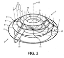
- FIG. 2 shows a second embodiment 1 of a lighting device 1 according to the present invention, which also has a small aspect ratio.
- the lighting device has a light source 11 comprising a three LEDs (not shown in detail), which are positioned in a compact packing design. During operation of the lighting device, these three LEDs emit light in a main direction, defining optical axis 12.
- the necessary wiring and driver electronics needed for driving the LEDs is not shown for clarity. They may be positioned on or in the substrate on which the three LEDs are positioned, or on a sub mount on which this substrate may be fastened.
- Lighting device 1 further comprises a reflective collimator 3, being composed of a plurality of reflective segments 4, 5, 6, and 7. These four reflective segments have a circular shape and are positioned symmetrically around optical axis 12 of the lighting device.
- the surfaces of the segments which face the optical axis 12 are reflective and curved such that they have a parabolic contour.
- the ring-shaped segments have been positioned such that they are mutually spaced and also spaced from the LEDs. So, air ventilation slits are present between neighboring segments. An additional air slit may be available between the housing (not shown) and the segment being positioned closest to the housing in or on which the light source is positioned.
- the segments are manufactured of a heat conducting material, typically aluminum or an aluminum alloy, by means of stamping or deep drawing from metal sheet.
- the so-produced reflective segments may additionally be provided with a reflective coating if the used material does not show sufficient reflectivity.
- Lighting device 1 also comprises a refractive collimator being designed as a rotational- symmetrically Fresnel lens 9.
- This lens has been manufactured of a transparent dielectric material.
- the optical axis of lens 9 substantially coincides with the optical axis 12 as described before.
- the various components of the lighting device, namely lens 9, reflective segments 4, 5, 6, 7, and the substrate on which the LEDs are positioned (not shown) are mutually connected with three connection means 10, which are rotational- symmetrically positioned around the LEDs.
- the connection means 10 are being manufactured from a heat conducting material, typically aluminum or an aluminum alloy.
- the substrate is also provided with a metal layer in order to transport the heat generated by the LEDs 11.
- the light generated by the LEDs is collimated by the reflective collimator 3 and the refractive collimator 9.
- a series of light beams 13 (all in a single plane X through optical axis 12) is indicated in the Figure.
- a portion of the light generated by the LEDs, which is emitted under an angle of more than approximately 30° away from the main direction of the emitted light (laterally emitted light) is reflected by the circular shaped segments of the reflective collimator towards a direction substantially parallel to said main direction.
- a portion of the light generated by the LEDs which is emitted under an angle less than approximately 30° away from the main direction of the emitted light (centrally emitted light), is refracted by the Fresnel lens towards a direction substantially parallel to said main direction.
- Both collimated light portions are combined to a single collimated light beam formed as a single light beam. It has been shown that with the here-described compact lighting device a good collimated light beam can be produced.
- Heat generated by the LEDs during operation of the lighting device will be conducted from the LEDs via the heat conductive layer on the substrate and the connection means 10 to the segments of the reflective collimator 3. Due to the presence of air ventilation slits between neighboring reflective segments and between the light source and its nearest reflective segment, a passive air stream may be generated due to temperature differences, which stream can enter and exit said space via the mentioned air slits. As a result, satisfactory heat dissipation is present in this embodiment of the lighting device according to the present invention.
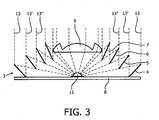
- Figure 3 shows a cross section of the lighting device 1 as shown in Figure 2 . More particularly, the cross section coincides with plane X mentioned before.
- This cross section shows the light source being composed of three LEDs 11, which are positioned in a compact packing design on substrate 8.
- Latter substrate (which forms the housing of the device) has been provided with a heat conductive metal layer for conducting heat generated by LEDs 11.
- the lighting device also comprises a reflective collimator 3 having a circular shape comprising reflective segments 4, 5, 6 and 7, as well as a refractive collimator 9.
- the four reflective segments all are curved, and, more precisely have a parabolic contour.
- the four segments are parts excised from paraboloids having mutually different focal lengths. A skilled person can select the focal lengths in such manner that slits with optimal widths between neighboring segments are obtained.
- FIG. 3 clearly shows that the neighboring reflective segments are positioned such that substantially no light emitted by the light source can escape between neighboring segments and that substantially no shadow areas are present at any of the segments.
- segments 4 and 5 are positioned such that light beam 13 just strikes the beneath rim of segment 5 and the upper rim of segment 4. Due to this precise positioning no light can escape between segments 4 and 5 and no shadow areas are present on the upper rim of segment 4. Displacement of a segment with respect to the others along the direction of the optical axis 12 would result in such light escape or shadow areas.
- parabolic segments are the optimal shape for a small source in the point source approximation, or for an extended source, when intensity but not efficiency is the primary goal, for an extended source optimizations to the basic parabolic segment contour can be applied to avoid light loss and shadowing between the reflective segments.
- shape modifications may be applied the upper and lower edge of each segment.
- the upper edge of the reflective segments can be modified and extended to make sure all light from the extended source that passes below the bottom edge of the previous inner segment is captured to avoid light loss.
- Such extension can have another parabolic profile with its focal point at the bottom edge of the previous inner segment.
- On the bottom edge of a reflective element an elliptical section can be applied, where one focal point is the edge of the extended light source, while the other focal point is the top edge of the previous inner segment.
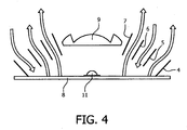
- Figure 4 schematically depicts in the invented lighting device the flow of air after being heated up by substrate 8 on which LEDs 11 are positioned.
- the heated air may escape from the space surrounded by the housing (here: substrate 8), reflective collimator 3 and refractive collimator 9 via air ventilation slits.
- An air circulation will cause exit of hot air from said space and entrance of cool air into said space by convection flow.
- no air slit is present between segment 4 and the housing.
- such slit can be provided easily be recessing the housing accordingly.
- FIG. 5 shows the cross section of another embodiment of the presently invented lighting system, being designed for an improved active air circulation.
- Substrate 8 of this embodiment is positioned on a housing 14 for storing wiring and driver electronics (not shown in detail).
- an air mover in this case a fan, has been installed.
- Said fan comprises a powering unit 16, arms 17 and two or more blades 18. Upon powering the fan, the arms and blades start rotating and causing an air flow.
- through holes 15 have been made in the substrate 8 within the outer area defined by the maximum dimensions of reflective collimator 3.
- an optimal air stream powered by the fan, can be designed.
- the air stream can remove the hot air accumulated in the space between the housing 14 (including substrate 8) and both collimators 3, 9. It can also efficiently cool the reflective segments of collimator 3. This is especially interesting in case that the segments should function as a heat sink. This is very useful in case that the reflective segments and the connection means are made of heat conductive material and that they are in heat conductive contact with LEDs 11 (for example via substrate 8).
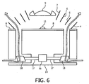
- FIG. 6 schematically depicts still another embodiment of the invented lighting device.
- housing 14 is provided with channels. These channels comprise at least one air mover, such as a blower, a fan or a synthetic jet.
- a fan has been installed in the bottom of housing 14.
- Said fan comprises a powering unit 16, arms 17 and two or more blades 18. Upon powering the fan, the arms and blades start rotating and causing an air flow.
- the arrows indicate a forced air flow from the bottom towards the top, an oppositely directed air flow also works well.
- the air mover could for example create an over pressure within the space defined by substrate 8 and both collimators 3 and 9 so that the air may escape via the air gaps positioned between the neighboring reflective segments. This design would efficiently cool the driver electronics, which is integrated in housing 14.
Landscapes
- Engineering & Computer Science (AREA)
- General Engineering & Computer Science (AREA)
- Non-Portable Lighting Devices Or Systems Thereof (AREA)
- Arrangement Of Elements, Cooling, Sealing, Or The Like Of Lighting Devices (AREA)
Applications Claiming Priority (3)
| Application Number | Priority Date | Filing Date | Title |
|---|---|---|---|
| US201261692258P | 2012-08-23 | 2012-08-23 | |
| US201261715879P | 2012-10-19 | 2012-10-19 | |
| PCT/IB2013/056346 WO2014030085A1 (en) | 2012-08-23 | 2013-08-02 | Lighting device with a led and an improved reflective collimator |
Publications (2)
| Publication Number | Publication Date |
|---|---|
| EP2888523A1 EP2888523A1 (en) | 2015-07-01 |
| EP2888523B1 true EP2888523B1 (en) | 2016-05-25 |
Family
ID=50149507
Family Applications (1)
| Application Number | Title | Priority Date | Filing Date |
|---|---|---|---|
| EP13766708.5A Not-in-force EP2888523B1 (en) | 2012-08-23 | 2013-08-02 | Lighting device with a led and an improved reflective collimator |
Country Status (6)
| Country | Link |
|---|---|
| US (1) | US20150219308A1 (zh) |
| EP (1) | EP2888523B1 (zh) |
| JP (1) | JP6275142B2 (zh) |
| CN (1) | CN104583669B (zh) |
| RU (1) | RU2636754C2 (zh) |
| WO (1) | WO2014030085A1 (zh) |
Cited By (1)
| Publication number | Priority date | Publication date | Assignee | Title |
|---|---|---|---|---|
| US10801698B2 (en) | 2017-03-20 | 2020-10-13 | Signify Holding B.V. | High visual comfort road and urban LED lighting |
Families Citing this family (22)
| Publication number | Priority date | Publication date | Assignee | Title |
|---|---|---|---|---|
| JP6121745B2 (ja) * | 2013-02-20 | 2017-04-26 | スタンレー電気株式会社 | 面照明発光装置 |
| EP2924347B1 (en) * | 2014-03-28 | 2017-12-06 | ARTEMIDE S.p.A. | Led lighting apparatus |
| US10357582B1 (en) | 2015-07-30 | 2019-07-23 | Vital Vio, Inc. | Disinfecting lighting device |
| WO2017019933A1 (en) | 2015-07-30 | 2017-02-02 | Vital Vio, Inc. | Single diode disinfection |
| US10918747B2 (en) | 2015-07-30 | 2021-02-16 | Vital Vio, Inc. | Disinfecting lighting device |
| CN105443996A (zh) * | 2015-12-10 | 2016-03-30 | 厦门立达信照明有限公司 | 小角度led照明装置 |
| JP6638074B2 (ja) * | 2016-01-12 | 2020-01-29 | ルミレッズ ホールディング ベーフェー | 光学素子の正確な位置決めを伴う照明構成 |
| US10261389B2 (en) * | 2016-06-22 | 2019-04-16 | Massachusetts Institute Of Technology | Methods and systems for optical beam steering |
| WO2017223299A1 (en) | 2016-06-22 | 2017-12-28 | Massachusetts Institute Of Technology | Methods and systems for optical beam steering |
| US10617774B2 (en) | 2017-12-01 | 2020-04-14 | Vital Vio, Inc. | Cover with disinfecting illuminated surface |
| US10309614B1 (en) * | 2017-12-05 | 2019-06-04 | Vital Vivo, Inc. | Light directing element |
| US10413626B1 (en) | 2018-03-29 | 2019-09-17 | Vital Vio, Inc. | Multiple light emitter for inactivating microorganisms |
| CN109458574A (zh) * | 2019-01-02 | 2019-03-12 | 中国科学院苏州生物医学工程技术研究所 | 一种多层反光杯及使用该多层反光杯的led灯具 |
| US11639897B2 (en) | 2019-03-29 | 2023-05-02 | Vyv, Inc. | Contamination load sensing device |
| EP3963359A1 (en) | 2019-04-30 | 2022-03-09 | Massachusetts Institute of Technology | Planar luneburg lens system for two-dimensional optical beam steering |
| US11541135B2 (en) | 2019-06-28 | 2023-01-03 | Vyv, Inc. | Multiple band visible light disinfection |
| CN110406460B (zh) * | 2019-07-02 | 2023-05-16 | 重庆长安汽车股份有限公司 | 一种出风口氛围灯结构 |
| WO2021030748A1 (en) | 2019-08-15 | 2021-02-18 | Vital Vio, Inc. | Devices configured to disinfect interiors |
| US11878084B2 (en) | 2019-09-20 | 2024-01-23 | Vyv, Inc. | Disinfecting light emitting subcomponent |
| CN111306521B (zh) * | 2020-02-26 | 2022-12-16 | 广东工业大学 | 一种三维热管散热装置 |
| BR112023019108A2 (pt) * | 2021-08-12 | 2024-04-30 | Obschestvo S Ogranichennoy Otvetstvennostyu Nauchno Proizvodstvennoe Predpriyatie Losev | Lâmpada de inspeção para pintores |
| US11441754B1 (en) | 2021-08-19 | 2022-09-13 | Ford Global Technologies, Llc | Vehicle lighting assembly with reflector system and light emitter |
Family Cites Families (64)
| Publication number | Priority date | Publication date | Assignee | Title |
|---|---|---|---|---|
| US1421506A (en) * | 1922-07-04 | Headlight | ||
| US3835342A (en) * | 1973-05-21 | 1974-09-10 | Ervin J | Radiant energy collector or reflector |
| US3805052A (en) * | 1973-07-02 | 1974-04-16 | Raytheon Co | Beam forming mirror apparatus |
| US3941458A (en) * | 1973-07-02 | 1976-03-02 | Raytheon Company | Catoptric lens arrangement |
| US3805051A (en) * | 1973-07-02 | 1974-04-16 | Raytheon Co | Catoptric lens arrangement |
| US4022186A (en) * | 1975-09-10 | 1977-05-10 | Northrup Jr Leonard L | Compound lens solar energy system |
| DE2615446A1 (de) * | 1976-04-09 | 1977-10-20 | Zimmermann Kg Rudolf | Stufenspiegel |
| US4337759A (en) * | 1979-10-10 | 1982-07-06 | John M. Popovich | Radiant energy concentration by optical total internal reflection |
| JPS5693205A (en) * | 1979-12-26 | 1981-07-28 | Matsushita Electric Ind Co Ltd | Illuminator |
| JPS6416013U (zh) * | 1987-07-21 | 1989-01-26 | ||
| US5050946A (en) * | 1990-09-27 | 1991-09-24 | Compaq Computer Corporation | Faceted light pipe |
| US5404869A (en) * | 1992-04-16 | 1995-04-11 | Tir Technologies, Inc. | Faceted totally internally reflecting lens with individually curved faces on facets |
| US5676453A (en) * | 1992-04-16 | 1997-10-14 | Tir Technologies, Inc. | Collimating TIR lens devices employing fluorescent light sources |
| US5806955A (en) * | 1992-04-16 | 1998-09-15 | Tir Technologies, Inc. | TIR lens for waveguide injection |
| US5655832A (en) * | 1992-04-16 | 1997-08-12 | Tir Technologies, Inc. | Multiple wavelength light processor |
| US5613769A (en) * | 1992-04-16 | 1997-03-25 | Tir Technologies, Inc. | Tir lens apparatus having non-circular configuration about an optical axis |
| US5276592A (en) * | 1992-08-05 | 1994-01-04 | General Electric Company | Headlight for motor vehicles |
| US5861633A (en) * | 1997-08-04 | 1999-01-19 | Con-Trol-Cure, Inc. | Irradiator apparatus |
| JP2001125197A (ja) * | 1999-10-27 | 2001-05-11 | Matsushita Electric Ind Co Ltd | 光源装置、照明装置および投写型表示装置 |
| JP2001283616A (ja) * | 2000-04-03 | 2001-10-12 | Stanley Electric Co Ltd | 車両用灯具 |
| US6971756B2 (en) * | 2000-12-18 | 2005-12-06 | Svv Technology Innovations, Inc. | Apparatus for collecting and converting radiant energy |
| US6620995B2 (en) * | 2001-03-30 | 2003-09-16 | Sergiy Victorovich Vasylyev | Non-imaging system for radiant energy flux transformation |
| US20030137754A1 (en) * | 2001-12-17 | 2003-07-24 | Vasylyev Sergiy Victorovich | Multistage system for radiant energy flux transformation |
| US7607429B2 (en) * | 2001-12-17 | 2009-10-27 | Svv Technology Innovations, Inc. | Multistage system for radiant energy flux transformation comprising an array of slat-like reflectors |
| US6612718B1 (en) * | 2002-03-01 | 2003-09-02 | Acuity Brands, Inc. | Optical flange for maintaining luminaire performance and smoothly coupling a lens to a reflector for enclosed luminaires |
| FR2846400B1 (fr) * | 2002-10-28 | 2005-10-07 | Valeo Vision | Feu de signalisation comportant un dispositif de recuperation et de repartition du flux lumineux vers un reflecteur annulaire |
| JP2004259541A (ja) * | 2003-02-25 | 2004-09-16 | Cateye Co Ltd | 照明器具 |
| US20050201100A1 (en) * | 2003-09-08 | 2005-09-15 | Cassarly William J. | Led lighting assembly |
| US7083297B2 (en) * | 2003-12-09 | 2006-08-01 | Surefire Llc | Flashlight with lens for transmitting central and off-axis light sources |
| US7029150B2 (en) * | 2004-01-23 | 2006-04-18 | Guide Corporation | Catadioptric light distribution system |
| US7481544B2 (en) * | 2004-03-05 | 2009-01-27 | Optical Research Associates | Grazing incidence relays |
| US7442871B2 (en) * | 2004-09-13 | 2008-10-28 | General Electric Company | Photovoltaic modules for solar concentrator |
| JP4954883B2 (ja) * | 2004-10-18 | 2012-06-20 | コーニンクレッカ フィリップス エレクトロニクス エヌ ヴィ | 高効率led光源装置 |
| US7455431B2 (en) * | 2005-03-11 | 2008-11-25 | Richard Brower | High efficiency light fixture |
| WO2007016363A2 (en) * | 2005-07-28 | 2007-02-08 | Light Prescriptions Innovators, Llc | Free-form lenticular optical elements and their application to condensers and headlamps |
| DE102005042358B3 (de) * | 2005-09-07 | 2007-03-01 | Audi Ag | Beleuchtungseinrichtung |
| EP1994336A2 (en) * | 2006-01-17 | 2008-11-26 | Soliant Energy, Inc. | A hybrid primary optical component for optical concentrators |
| TWI299311B (en) * | 2006-09-27 | 2008-08-01 | Ind Tech Res Inst | Illuminating device |
| US20090091936A1 (en) * | 2007-10-04 | 2009-04-09 | Koester George H | Focal point projection light signal comprising a beam concentrator |
| US8049974B2 (en) * | 2008-06-09 | 2011-11-01 | Raytheon Company | Method and apparatus for accurately aligning optical components |
| US7575346B1 (en) * | 2008-07-22 | 2009-08-18 | Sunonwealth Electric Machine Industry Co., Ltd. | Lamp |
| US7891842B2 (en) * | 2008-08-07 | 2011-02-22 | Hong Kong Applied Science And Technology Research Institute Co. Ltd. | Heat-dissipating reflector for lighting device |
| US7964858B2 (en) * | 2008-10-21 | 2011-06-21 | Applied Materials, Inc. | Ultraviolet reflector with coolant gas holes and method |
| AU2009308970A1 (en) * | 2008-10-31 | 2010-05-06 | Code 3, Inc. | Light fixture with inner and outer trough reflectors |
| DE102009017495B4 (de) * | 2009-02-11 | 2020-07-09 | Osram Opto Semiconductors Gmbh | Beleuchtungseinrichtung |
| CN101818889A (zh) * | 2009-02-27 | 2010-09-01 | 富准精密工业(深圳)有限公司 | 发光二极管灯具 |
| TWI366645B (en) * | 2009-03-24 | 2012-06-21 | Young Green Energy Co | Illumination apparatus |
| US20100295436A1 (en) * | 2009-05-19 | 2010-11-25 | Alex Horng | Lamp |
| CN102803836A (zh) * | 2009-06-11 | 2012-11-28 | 皇家飞利浦电子股份有限公司 | 照明设备 |
| US9291327B2 (en) * | 2009-07-06 | 2016-03-22 | Solais Lighting, Inc. | Light conditioning for high-brightness white-light illumination sources |
| US20120212960A1 (en) * | 2009-07-06 | 2012-08-23 | Rodriguez Edward T | Cooling solid state high-brightness white-light illumination sources |
| TWM372923U (en) * | 2009-08-14 | 2010-01-21 | Risun Expanse Corp | Lamp structure |
| NL2003471C2 (en) * | 2009-09-11 | 2012-05-08 | Stichting Administratiekantoor Vormgroup | Led assembly. |
| CA2794766C (en) * | 2010-03-31 | 2018-09-25 | Ats Automation Tooling Systems Inc. | Light generator systems and methods |
| US8506105B2 (en) * | 2010-08-25 | 2013-08-13 | Generla Electric Company | Thermal management systems for solid state lighting and other electronic systems |
| RU103704U1 (ru) * | 2010-12-29 | 2011-04-27 | Общество с ограниченной ответственностью "Воля" | Светодиодный облучатель для растениеводства |
| RU110814U1 (ru) * | 2011-06-14 | 2011-11-27 | Валерий Иванович Орехов | Светодиодный светильник |
| DE202011103265U1 (de) * | 2011-07-16 | 2011-12-20 | Automotive Lighting Reutlingen Gmbh | Beleuchtungseinrichtung mit einer aufgeteilten, nicht zusammenhängenden Reflexionsfläche |
| CN103975190A (zh) * | 2011-09-26 | 2014-08-06 | 马斯科公司 | 具有多光源准直器的照明系统及其操作方法 |
| US9500356B2 (en) * | 2012-01-09 | 2016-11-22 | Tai-Her Yang | Heat dissipater with axial and radial air aperture and application device thereof |
| US9146031B2 (en) * | 2012-04-13 | 2015-09-29 | Bridgelux, Inc. | Lighting module |
| US20140175979A1 (en) * | 2012-05-09 | 2014-06-26 | Stray Light Optical Technologies | Light emitting plasma lighting apparatus having rf shielding baffles |
| US8915624B2 (en) * | 2012-05-22 | 2014-12-23 | Cooper Technologies Company | Cooling heat-generating components of a light fixture |
| KR20150046076A (ko) * | 2012-08-02 | 2015-04-29 | 프라엔 코포레이션 | 낮은 프로파일 다중 렌즈 tir |
-
2013
- 2013-08-02 CN CN201380043994.9A patent/CN104583669B/zh not_active Expired - Fee Related
- 2013-08-02 RU RU2015110050A patent/RU2636754C2/ru not_active IP Right Cessation
- 2013-08-02 US US14/423,274 patent/US20150219308A1/en not_active Abandoned
- 2013-08-02 JP JP2015527980A patent/JP6275142B2/ja not_active Expired - Fee Related
- 2013-08-02 WO PCT/IB2013/056346 patent/WO2014030085A1/en active Application Filing
- 2013-08-02 EP EP13766708.5A patent/EP2888523B1/en not_active Not-in-force
Cited By (1)
| Publication number | Priority date | Publication date | Assignee | Title |
|---|---|---|---|---|
| US10801698B2 (en) | 2017-03-20 | 2020-10-13 | Signify Holding B.V. | High visual comfort road and urban LED lighting |
Also Published As
| Publication number | Publication date |
|---|---|
| WO2014030085A1 (en) | 2014-02-27 |
| EP2888523A1 (en) | 2015-07-01 |
| JP6275142B2 (ja) | 2018-02-07 |
| RU2015110050A (ru) | 2016-10-10 |
| US20150219308A1 (en) | 2015-08-06 |
| RU2636754C2 (ru) | 2017-11-28 |
| JP2015531152A (ja) | 2015-10-29 |
| CN104583669A (zh) | 2015-04-29 |
| CN104583669B (zh) | 2017-07-07 |
Similar Documents
| Publication | Publication Date | Title |
|---|---|---|
| EP2888523B1 (en) | Lighting device with a led and an improved reflective collimator | |
| EP2515031B1 (en) | Optical system for batwing distribution | |
| EP1660918B1 (en) | Circumferentially emitting luminaires and lens elements formed by transverse-axis profile-sweeps | |
| US7377671B2 (en) | Etendue-squeezing illumination optics | |
| US7008079B2 (en) | Composite reflecting surface for linear LED array | |
| US7712931B1 (en) | Sweep collimator | |
| US9470882B2 (en) | Optical arrangement for a solid-state lamp | |
| CN109563980B (zh) | 照明模块和灯具 | |
| JP6096180B2 (ja) | 発光ダイオード光源 | |
| US20140078732A1 (en) | LED Optical Assembly | |
| US9804321B1 (en) | LED optics for bulbs and luminaires | |
| JP2007080565A (ja) | 光源装置およびアレイ光源装置 | |
| JP2015179612A (ja) | 照明装置 | |
| JP6186002B2 (ja) | 間接照明のための照明装置 | |
| US9255673B2 (en) | LED bulb having an adjustable light-distribution profile | |
| JP6094618B2 (ja) | ランプ | |
| US10184639B2 (en) | Method and apparatus for subtending light | |
| US9052088B2 (en) | Tuned composite optical arrangement for LED array | |
| KR102471181B1 (ko) | 조명 장치 | |
| US20150099940A1 (en) | Luminaire with tir reflector | |
| KR20100137752A (ko) | 반사식 조명장치 |
Legal Events
| Date | Code | Title | Description |
|---|---|---|---|
| PUAI | Public reference made under article 153(3) epc to a published international application that has entered the european phase |
Free format text: ORIGINAL CODE: 0009012 |
|
| 17P | Request for examination filed |
Effective date: 20150323 |
|
| AK | Designated contracting states |
Kind code of ref document: A1 Designated state(s): AL AT BE BG CH CY CZ DE DK EE ES FI FR GB GR HR HU IE IS IT LI LT LU LV MC MK MT NL NO PL PT RO RS SE SI SK SM TR |
|
| AX | Request for extension of the european patent |
Extension state: BA ME |
|
| GRAP | Despatch of communication of intention to grant a patent |
Free format text: ORIGINAL CODE: EPIDOSNIGR1 |
|
| RIC1 | Information provided on ipc code assigned before grant |
Ipc: F21V 5/04 20060101AFI20150918BHEP Ipc: F21Y 103/00 20060101ALN20150918BHEP Ipc: F21V 29/83 20150101ALI20150918BHEP Ipc: F21V 7/00 20060101ALI20150918BHEP Ipc: F21V 29/505 20150101ALI20150918BHEP Ipc: F21V 29/67 20150101ALN20150918BHEP Ipc: F21Y 101/02 20060101ALN20150918BHEP Ipc: F21V 7/04 20060101ALI20150918BHEP |
|
| DAX | Request for extension of the european patent (deleted) | ||
| INTG | Intention to grant announced |
Effective date: 20151028 |
|
| RIC1 | Information provided on ipc code assigned before grant |
Ipc: F21V 5/04 20060101AFI20151125BHEP Ipc: F21Y 103/00 20060101ALN20151125BHEP Ipc: F21V 29/83 20150101ALI20151125BHEP Ipc: F21Y 101/02 20060101ALN20151125BHEP Ipc: F21V 7/00 20060101ALI20151125BHEP Ipc: F21V 29/67 20150101ALN20151125BHEP Ipc: F21V 29/505 20150101ALI20151125BHEP Ipc: F21V 7/04 20060101ALI20151125BHEP |
|
| INTG | Intention to grant announced |
Effective date: 20151208 |
|
| GRAS | Grant fee paid |
Free format text: ORIGINAL CODE: EPIDOSNIGR3 |
|
| REG | Reference to a national code |
Ref country code: DE Ref legal event code: R079 Ref document number: 602013008073 Country of ref document: DE Free format text: PREVIOUS MAIN CLASS: F21V0007200000 Ipc: F21V0005040000 |
|
| GRAA | (expected) grant |
Free format text: ORIGINAL CODE: 0009210 |
|
| RIC1 | Information provided on ipc code assigned before grant |
Ipc: F21V 7/00 20060101ALI20160413BHEP Ipc: F21V 7/04 20060101ALI20160413BHEP Ipc: F21V 29/83 20150101ALI20160413BHEP Ipc: F21Y 115/10 20160101ALN20160413BHEP Ipc: F21V 29/67 20150101ALN20160413BHEP Ipc: F21Y 103/10 20160101ALN20160413BHEP Ipc: F21V 5/04 20060101AFI20160413BHEP Ipc: F21V 29/505 20150101ALI20160413BHEP |
|
| AK | Designated contracting states |
Kind code of ref document: B1 Designated state(s): AL AT BE BG CH CY CZ DE DK EE ES FI FR GB GR HR HU IE IS IT LI LT LU LV MC MK MT NL NO PL PT RO RS SE SI SK SM TR |
|
| REG | Reference to a national code |
Ref country code: GB Ref legal event code: FG4D |
|
| REG | Reference to a national code |
Ref country code: CH Ref legal event code: EP |
|
| REG | Reference to a national code |
Ref country code: IE Ref legal event code: FG4D Ref country code: AT Ref legal event code: REF Ref document number: 802640 Country of ref document: AT Kind code of ref document: T Effective date: 20160615 |
|
| REG | Reference to a national code |
Ref country code: DE Ref legal event code: R096 Ref document number: 602013008073 Country of ref document: DE |
|
| RAP2 | Party data changed (patent owner data changed or rights of a patent transferred) |
Owner name: PHILIPS LIGHTING HOLDING B.V. |
|
| REG | Reference to a national code |
Ref country code: FR Ref legal event code: PLFP Year of fee payment: 4 |
|
| REG | Reference to a national code |
Ref country code: LT Ref legal event code: MG4D |
|
| REG | Reference to a national code |
Ref country code: NL Ref legal event code: MP Effective date: 20160525 |
|
| PG25 | Lapsed in a contracting state [announced via postgrant information from national office to epo] |
Ref country code: NO Free format text: LAPSE BECAUSE OF FAILURE TO SUBMIT A TRANSLATION OF THE DESCRIPTION OR TO PAY THE FEE WITHIN THE PRESCRIBED TIME-LIMIT Effective date: 20160825 Ref country code: FI Free format text: LAPSE BECAUSE OF FAILURE TO SUBMIT A TRANSLATION OF THE DESCRIPTION OR TO PAY THE FEE WITHIN THE PRESCRIBED TIME-LIMIT Effective date: 20160525 Ref country code: LT Free format text: LAPSE BECAUSE OF FAILURE TO SUBMIT A TRANSLATION OF THE DESCRIPTION OR TO PAY THE FEE WITHIN THE PRESCRIBED TIME-LIMIT Effective date: 20160525 Ref country code: NL Free format text: LAPSE BECAUSE OF FAILURE TO SUBMIT A TRANSLATION OF THE DESCRIPTION OR TO PAY THE FEE WITHIN THE PRESCRIBED TIME-LIMIT Effective date: 20160525 |
|
| REG | Reference to a national code |
Ref country code: GB Ref legal event code: 732E Free format text: REGISTERED BETWEEN 20161006 AND 20161012 |
|
| REG | Reference to a national code |
Ref country code: AT Ref legal event code: MK05 Ref document number: 802640 Country of ref document: AT Kind code of ref document: T Effective date: 20160525 |
|
| PG25 | Lapsed in a contracting state [announced via postgrant information from national office to epo] |
Ref country code: RS Free format text: LAPSE BECAUSE OF FAILURE TO SUBMIT A TRANSLATION OF THE DESCRIPTION OR TO PAY THE FEE WITHIN THE PRESCRIBED TIME-LIMIT Effective date: 20160525 Ref country code: GR Free format text: LAPSE BECAUSE OF FAILURE TO SUBMIT A TRANSLATION OF THE DESCRIPTION OR TO PAY THE FEE WITHIN THE PRESCRIBED TIME-LIMIT Effective date: 20160826 Ref country code: SE Free format text: LAPSE BECAUSE OF FAILURE TO SUBMIT A TRANSLATION OF THE DESCRIPTION OR TO PAY THE FEE WITHIN THE PRESCRIBED TIME-LIMIT Effective date: 20160525 Ref country code: PT Free format text: LAPSE BECAUSE OF FAILURE TO SUBMIT A TRANSLATION OF THE DESCRIPTION OR TO PAY THE FEE WITHIN THE PRESCRIBED TIME-LIMIT Effective date: 20160926 Ref country code: ES Free format text: LAPSE BECAUSE OF FAILURE TO SUBMIT A TRANSLATION OF THE DESCRIPTION OR TO PAY THE FEE WITHIN THE PRESCRIBED TIME-LIMIT Effective date: 20160525 Ref country code: HR Free format text: LAPSE BECAUSE OF FAILURE TO SUBMIT A TRANSLATION OF THE DESCRIPTION OR TO PAY THE FEE WITHIN THE PRESCRIBED TIME-LIMIT Effective date: 20160525 Ref country code: LV Free format text: LAPSE BECAUSE OF FAILURE TO SUBMIT A TRANSLATION OF THE DESCRIPTION OR TO PAY THE FEE WITHIN THE PRESCRIBED TIME-LIMIT Effective date: 20160525 |
|
| PG25 | Lapsed in a contracting state [announced via postgrant information from national office to epo] |
Ref country code: IT Free format text: LAPSE BECAUSE OF FAILURE TO SUBMIT A TRANSLATION OF THE DESCRIPTION OR TO PAY THE FEE WITHIN THE PRESCRIBED TIME-LIMIT Effective date: 20160525 Ref country code: BE Free format text: LAPSE BECAUSE OF NON-PAYMENT OF DUE FEES Effective date: 20160831 |
|
| PG25 | Lapsed in a contracting state [announced via postgrant information from national office to epo] |
Ref country code: DK Free format text: LAPSE BECAUSE OF FAILURE TO SUBMIT A TRANSLATION OF THE DESCRIPTION OR TO PAY THE FEE WITHIN THE PRESCRIBED TIME-LIMIT Effective date: 20160525 Ref country code: CZ Free format text: LAPSE BECAUSE OF FAILURE TO SUBMIT A TRANSLATION OF THE DESCRIPTION OR TO PAY THE FEE WITHIN THE PRESCRIBED TIME-LIMIT Effective date: 20160525 Ref country code: EE Free format text: LAPSE BECAUSE OF FAILURE TO SUBMIT A TRANSLATION OF THE DESCRIPTION OR TO PAY THE FEE WITHIN THE PRESCRIBED TIME-LIMIT Effective date: 20160525 Ref country code: RO Free format text: LAPSE BECAUSE OF FAILURE TO SUBMIT A TRANSLATION OF THE DESCRIPTION OR TO PAY THE FEE WITHIN THE PRESCRIBED TIME-LIMIT Effective date: 20160525 Ref country code: SK Free format text: LAPSE BECAUSE OF FAILURE TO SUBMIT A TRANSLATION OF THE DESCRIPTION OR TO PAY THE FEE WITHIN THE PRESCRIBED TIME-LIMIT Effective date: 20160525 |
|
| REG | Reference to a national code |
Ref country code: DE Ref legal event code: R082 Ref document number: 602013008073 Country of ref document: DE Representative=s name: MEISSNER BOLTE PATENTANWAELTE RECHTSANWAELTE P, DE Ref country code: DE Ref legal event code: R081 Ref document number: 602013008073 Country of ref document: DE Owner name: PHILIPS LIGHTING HOLDING B.V., NL Free format text: FORMER OWNER: KONINKLIJKE PHILIPS N.V., EINDHOVEN, NL |
|
| PG25 | Lapsed in a contracting state [announced via postgrant information from national office to epo] |
Ref country code: AT Free format text: LAPSE BECAUSE OF FAILURE TO SUBMIT A TRANSLATION OF THE DESCRIPTION OR TO PAY THE FEE WITHIN THE PRESCRIBED TIME-LIMIT Effective date: 20160525 Ref country code: SM Free format text: LAPSE BECAUSE OF FAILURE TO SUBMIT A TRANSLATION OF THE DESCRIPTION OR TO PAY THE FEE WITHIN THE PRESCRIBED TIME-LIMIT Effective date: 20160525 Ref country code: PL Free format text: LAPSE BECAUSE OF FAILURE TO SUBMIT A TRANSLATION OF THE DESCRIPTION OR TO PAY THE FEE WITHIN THE PRESCRIBED TIME-LIMIT Effective date: 20160525 Ref country code: BE Free format text: LAPSE BECAUSE OF FAILURE TO SUBMIT A TRANSLATION OF THE DESCRIPTION OR TO PAY THE FEE WITHIN THE PRESCRIBED TIME-LIMIT Effective date: 20160525 |
|
| REG | Reference to a national code |
Ref country code: DE Ref legal event code: R097 Ref document number: 602013008073 Country of ref document: DE |
|
| PG25 | Lapsed in a contracting state [announced via postgrant information from national office to epo] |
Ref country code: MC Free format text: LAPSE BECAUSE OF FAILURE TO SUBMIT A TRANSLATION OF THE DESCRIPTION OR TO PAY THE FEE WITHIN THE PRESCRIBED TIME-LIMIT Effective date: 20160525 |
|
| PLBE | No opposition filed within time limit |
Free format text: ORIGINAL CODE: 0009261 |
|
| REG | Reference to a national code |
Ref country code: CH Ref legal event code: PL |
|
| STAA | Information on the status of an ep patent application or granted ep patent |
Free format text: STATUS: NO OPPOSITION FILED WITHIN TIME LIMIT |
|
| PG25 | Lapsed in a contracting state [announced via postgrant information from national office to epo] |
Ref country code: LI Free format text: LAPSE BECAUSE OF NON-PAYMENT OF DUE FEES Effective date: 20160831 Ref country code: CH Free format text: LAPSE BECAUSE OF NON-PAYMENT OF DUE FEES Effective date: 20160831 |
|
| 26N | No opposition filed |
Effective date: 20170228 |
|
| PG25 | Lapsed in a contracting state [announced via postgrant information from national office to epo] |
Ref country code: SI Free format text: LAPSE BECAUSE OF FAILURE TO SUBMIT A TRANSLATION OF THE DESCRIPTION OR TO PAY THE FEE WITHIN THE PRESCRIBED TIME-LIMIT Effective date: 20160525 |
|
| REG | Reference to a national code |
Ref country code: IE Ref legal event code: MM4A |
|
| PG25 | Lapsed in a contracting state [announced via postgrant information from national office to epo] |
Ref country code: IE Free format text: LAPSE BECAUSE OF NON-PAYMENT OF DUE FEES Effective date: 20160802 |
|
| REG | Reference to a national code |
Ref country code: FR Ref legal event code: PLFP Year of fee payment: 5 |
|
| PG25 | Lapsed in a contracting state [announced via postgrant information from national office to epo] |
Ref country code: LU Free format text: LAPSE BECAUSE OF NON-PAYMENT OF DUE FEES Effective date: 20160802 |
|
| PG25 | Lapsed in a contracting state [announced via postgrant information from national office to epo] |
Ref country code: HU Free format text: LAPSE BECAUSE OF FAILURE TO SUBMIT A TRANSLATION OF THE DESCRIPTION OR TO PAY THE FEE WITHIN THE PRESCRIBED TIME-LIMIT; INVALID AB INITIO Effective date: 20130802 |
|
| PG25 | Lapsed in a contracting state [announced via postgrant information from national office to epo] |
Ref country code: MT Free format text: LAPSE BECAUSE OF NON-PAYMENT OF DUE FEES Effective date: 20160831 Ref country code: IS Free format text: LAPSE BECAUSE OF FAILURE TO SUBMIT A TRANSLATION OF THE DESCRIPTION OR TO PAY THE FEE WITHIN THE PRESCRIBED TIME-LIMIT Effective date: 20160525 Ref country code: MK Free format text: LAPSE BECAUSE OF FAILURE TO SUBMIT A TRANSLATION OF THE DESCRIPTION OR TO PAY THE FEE WITHIN THE PRESCRIBED TIME-LIMIT Effective date: 20160525 Ref country code: CY Free format text: LAPSE BECAUSE OF FAILURE TO SUBMIT A TRANSLATION OF THE DESCRIPTION OR TO PAY THE FEE WITHIN THE PRESCRIBED TIME-LIMIT Effective date: 20160525 |
|
| PG25 | Lapsed in a contracting state [announced via postgrant information from national office to epo] |
Ref country code: BG Free format text: LAPSE BECAUSE OF FAILURE TO SUBMIT A TRANSLATION OF THE DESCRIPTION OR TO PAY THE FEE WITHIN THE PRESCRIBED TIME-LIMIT Effective date: 20160525 |
|
| REG | Reference to a national code |
Ref country code: FR Ref legal event code: PLFP Year of fee payment: 6 |
|
| PG25 | Lapsed in a contracting state [announced via postgrant information from national office to epo] |
Ref country code: TR Free format text: LAPSE BECAUSE OF FAILURE TO SUBMIT A TRANSLATION OF THE DESCRIPTION OR TO PAY THE FEE WITHIN THE PRESCRIBED TIME-LIMIT Effective date: 20160525 Ref country code: AL Free format text: LAPSE BECAUSE OF FAILURE TO SUBMIT A TRANSLATION OF THE DESCRIPTION OR TO PAY THE FEE WITHIN THE PRESCRIBED TIME-LIMIT Effective date: 20160525 |
|
| PGFP | Annual fee paid to national office [announced via postgrant information from national office to epo] |
Ref country code: FR Payment date: 20190827 Year of fee payment: 7 |
|
| PGFP | Annual fee paid to national office [announced via postgrant information from national office to epo] |
Ref country code: GB Payment date: 20190829 Year of fee payment: 7 |
|
| PGFP | Annual fee paid to national office [announced via postgrant information from national office to epo] |
Ref country code: DE Payment date: 20191031 Year of fee payment: 7 |
|
| REG | Reference to a national code |
Ref country code: DE Ref legal event code: R119 Ref document number: 602013008073 Country of ref document: DE |
|
| GBPC | Gb: european patent ceased through non-payment of renewal fee |
Effective date: 20200802 |
|
| PG25 | Lapsed in a contracting state [announced via postgrant information from national office to epo] |
Ref country code: DE Free format text: LAPSE BECAUSE OF NON-PAYMENT OF DUE FEES Effective date: 20210302 Ref country code: FR Free format text: LAPSE BECAUSE OF NON-PAYMENT OF DUE FEES Effective date: 20200831 |
|
| PG25 | Lapsed in a contracting state [announced via postgrant information from national office to epo] |
Ref country code: GB Free format text: LAPSE BECAUSE OF NON-PAYMENT OF DUE FEES Effective date: 20200802 |