EP2888477B1 - Membrandosierpumpe mit einem entgasungssystem - Google Patents
Membrandosierpumpe mit einem entgasungssystem Download PDFInfo
- Publication number
- EP2888477B1 EP2888477B1 EP13759634.2A EP13759634A EP2888477B1 EP 2888477 B1 EP2888477 B1 EP 2888477B1 EP 13759634 A EP13759634 A EP 13759634A EP 2888477 B1 EP2888477 B1 EP 2888477B1
- Authority
- EP
- European Patent Office
- Prior art keywords
- check valve
- metering pump
- diaphragm metering
- actuator
- discharge side
- Prior art date
- Legal status (The legal status is an assumption and is not a legal conclusion. Google has not performed a legal analysis and makes no representation as to the accuracy of the status listed.)
- Active
Links
- 238000007872 degassing Methods 0.000 title claims description 30
- 239000012530 fluid Substances 0.000 claims description 29
- 239000007789 gas Substances 0.000 claims description 25
- 239000007788 liquid Substances 0.000 claims description 19
- 238000000034 method Methods 0.000 claims description 9
- 230000000977 initiatory effect Effects 0.000 claims description 3
- 230000003213 activating effect Effects 0.000 claims 1
- 238000005086 pumping Methods 0.000 description 4
- 238000007789 sealing Methods 0.000 description 2
- 235000014676 Phragmites communis Nutrition 0.000 description 1
- 238000009825 accumulation Methods 0.000 description 1
- 238000004891 communication Methods 0.000 description 1
- 230000006835 compression Effects 0.000 description 1
- 238000007906 compression Methods 0.000 description 1
- 238000006073 displacement reaction Methods 0.000 description 1
- 230000005484 gravity Effects 0.000 description 1
- 238000002955 isolation Methods 0.000 description 1
- 239000000463 material Substances 0.000 description 1
- 238000012986 modification Methods 0.000 description 1
- 230000004048 modification Effects 0.000 description 1
- 238000009428 plumbing Methods 0.000 description 1
- 238000010926 purge Methods 0.000 description 1
- 125000006850 spacer group Chemical group 0.000 description 1
Images





Classifications
-
- F—MECHANICAL ENGINEERING; LIGHTING; HEATING; WEAPONS; BLASTING
- F04—POSITIVE - DISPLACEMENT MACHINES FOR LIQUIDS; PUMPS FOR LIQUIDS OR ELASTIC FLUIDS
- F04B—POSITIVE-DISPLACEMENT MACHINES FOR LIQUIDS; PUMPS
- F04B13/00—Pumps specially modified to deliver fixed or variable measured quantities
-
- F—MECHANICAL ENGINEERING; LIGHTING; HEATING; WEAPONS; BLASTING
- F04—POSITIVE - DISPLACEMENT MACHINES FOR LIQUIDS; PUMPS FOR LIQUIDS OR ELASTIC FLUIDS
- F04B—POSITIVE-DISPLACEMENT MACHINES FOR LIQUIDS; PUMPS
- F04B43/00—Machines, pumps, or pumping installations having flexible working members
- F04B43/02—Machines, pumps, or pumping installations having flexible working members having plate-like flexible members, e.g. diaphragms
-
- F—MECHANICAL ENGINEERING; LIGHTING; HEATING; WEAPONS; BLASTING
- F04—POSITIVE - DISPLACEMENT MACHINES FOR LIQUIDS; PUMPS FOR LIQUIDS OR ELASTIC FLUIDS
- F04B—POSITIVE-DISPLACEMENT MACHINES FOR LIQUIDS; PUMPS
- F04B53/00—Component parts, details or accessories not provided for in, or of interest apart from, groups F04B1/00 - F04B23/00 or F04B39/00 - F04B47/00
- F04B53/06—Venting
Definitions
- Exemplary embodiments pertain to the art of diaphragm metering pumps and, more particularly, to a diaphragm metering pump having a degassing system.
- Diaphragm metering pumps generally draw in a fluid from a source to an inlet at a first pressure, and discharge the fluid through an outlet at a second pressure.
- gas entrained in the fluid, or developed as a consequence of pumping may become trapped in a head portion of the pump causing a vapor lock condition. In such cases, fluid discharge may be reduced or even arrested.
- many diaphragm metering pumps include a bleed valve that is manually or automatically activated to allow trapped gas to escape. In some cases, the trapped gas is discharged to ambient. In other cases, the trapped gas, along with a portion of discharged fluid, is passed back to the source through a piping system.
- US2004062662 A1 relates to a diaphragm metering pump suitable for metering an effervescent gas.
- the pump has a pump head with a product chamber having an inlet end with a one-way inlet valve and an outlet end with a one-way outlet valve.
- a displaceable diaphragm member defines a boundary of the product chamber.
- the diaphragm member is capable of being reciprocated to cause pumping displacements.
- a discharge side is disposed downstream from the outlet valve.
- a passageway is disposed in fluid communication between the discharge side and the product chamber.
- a valve is disposed in the passageway. The valve is opened intermittently to allow liquid to re-enter the product chamber in an amount effective to purge gas from the product chamber to prevent loss of prime.
- DE2803470 A1 relates to a pump head that has a pumping chamber which can be linked to the suction or compression side via a pulsating lifting element.
- the lifting element is actuated electromagnetically and the travel is restricted. It will avoid the collection of gases in the pumping chamber.
- DE3631984 relates to a dosing pump.
- a diaphragm metering pump including a pump body having a head portion including a suction side and a discharge side defining a flow path.
- a valve seat is arranged at the discharge side and a check valve is arranged at the valve seat.
- a degassing system includes a check valve actuator operatively connected to the check valve. The check valve actuator is selectively activated to unseat the check valve from the valve seat to allow gases trapped in the head portion to pass through the discharge side.
- the method includes drawing a liquid from a liquid source through a suction side of a diaphragm metering pump, passing the liquid from the suction side into a head portion of the diaphragm metering pump, guiding the liquid through a check valve from the head portion to a discharge side of the diaphragm metering pump, and initiating a check valve actuator to unseat the check valve allowing gases collected in the head portion to pass through the discharge portion.
- Diaphragm metering pump 2 in accordance with an exemplary embodiment is illustrated generally at 2 in FIG. 1 .
- Diaphragm metering pump 2 includes a pump body 4 having an actuator portion 6 and a head portion 8.
- Actuator portion 6 includes a rotating shaft 10 coupled to an eccentric mechanism 12.
- Eccentric mechanism 12 is coupled to a connecting rod 14 that connects with a pump diaphragm 16.
- Eccentric mechanism 12 and connecting rod 14 create a reciprocating motion at pump diaphragm 16 that leads to pressure changes within a pump chamber 20 carried by head portion 8.
- Pump chamber 20 includes a suction side 23 and a pressure or discharge side 25.
- Suction side 23 is fluidically coupled to a fluid source 28.
- Discharge side 25 is fluidically coupled to a discharge flow path 30 that leads to a fluid destination 32. Fluid destination 32 may take on a variety of forms.
- Suction side 23 includes an inlet fitting 36 including a check valve 38 shown in the form of a check ball 40 that selectively rests upon a valve seat 43.
- the term "check valve” should be understood to mean a valve having a checking element configured to allow fluid to pass in one direction and arrest fluid flow in an opposing direction.
- Check valve 38 allows fluid to enter pump chamber 20 from fluid source 28 during a suction stroke and prevents fluid from exiting through inlet fitting 36 during a pressure stroke.
- a discharge fitting 56 is fluidically connected to discharge side 25 through a check valve 58.
- check valve 58 is shown in the form of a check ball 60 that selectively rests upon a valve seat 62.
- Check valve 58 allows fluid to flow from pump chamber 20 toward fluid destination 32 during a pressure stroke and prevents fluid from being ingested into pump chamber 20 through discharge fitting 56 during a suction stroke.
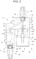
- diaphragm metering pump 2 is provided with a degassing system 66 fluidically connected to discharge side 25 of pump chamber 20.
- degassing system 66 includes a support member 71 having a mounting surface 75, and an outlet 76. Mounting surface 75 is secured to head portion 8 at discharge side 25.
- Outlet 76 includes a check valve receiving portion 77 that houses check ball 60 and valve seat 62.
- Support member 71 includes a first passage 78 and a second passage 79.
- First passage 78 includes a first end 83 that extends from mounting surface 75 to second end 84 that fluidically connects with check valve receiving portion 77.
- Second passage 79 includes a first end portion 86 to a second end portion 87 that fluidically connects with first passage 78 and check valve receiving portion 77. At this point it should be understood that second passage 79 does not conduct a fluid but rather serves as a passageway as will be described more fully below.
- Degassing system 66 includes a check valve actuator 96 connected to mounting surface 75 though a mounting block 97.
- Check valve actuator 96 takes the form of a linear actuator 99 shown in the form of a solenoid 100.
- Solenoid 100 includes a coil 104 and a plunger 107.
- Plunger 107 acts upon an actuating pin assembly 109 that projects through second passage 79 along a path that is substantially parallel to discharge flow path 30.
- plunger 107 acts upon actuating pin assembly 109.
- Actuating pin assembly 109 extends along second passage 79, contacts and unseats check ball 60 allowing gases trapped within pump chamber 20 to pass from discharge flow path 30 to fluid destination 32.
- Degassing system 66 is also shown to include a sealing member 110 that takes the form of an isolation diaphragm or seal 113 that extends about actuating pin assembly 109 to prevent fluid from exiting second passage 79.
- check valve actuator 96 includes a return spring 115 that biases actuating pin assembly 109 into a ready position as shown in FIG. 2 .
- Degassing system 120 includes a support member 124 having a first mounting surface 126 and a second mounting surface 128.
- First mounting surface 126 is coupled to head portion 8.
- Support member 124 also includes an outlet 133 and a check valve receiving portion 136 that houses check ball 60 and valve seat 62.
- Outlet 133 is arranged opposite to check valve receiving portion 136 and is fluidically connected with discharge fitting 56.
- First and second passages 140 and 141 extend within support member 124.
- First passage 140 includes a first end 144 that extends from check valve receiving portion 136 to a second end 145 fluidically connected to outlet 133.
- Second passage 141 includes a first end portion 147 that extends from check valve receiving portion 136 to a second end portion 148 at second mounting surface 128.
- Degassing system 120 is also shown to include a check valve actuator 154 supported from second mounting surface 128.
- Check valve actuator 154 takes the form of a linear actuator 156.
- Linear actuator 156 is shown as a solenoid 158 having a plunger 161 that acts upon an actuating pin 162 through a spacer 163 and a diaphragm seal 164.
- Solenoid 158 is also shown to include a return spring 165 that biases actuating pin 162 into a ready position such as shown in FIG. 3 .
- Actuating pin 162 is selectively acted upon by plunger 161 to shift check ball 60 from valve seat 62 to allow gases accumulating in head portion 8 to flow through discharge fitting 56.
- Actuating pin 162 projects through second passage 141 along a path that is substantially perpendicular to discharge flow path 30 to directly contact and unseat check ball 60.
- First passage 190 includes a first end 194 that extends from check valve receiving portion 186 to a second end 195 through an angled portion 196. Second end 195 is fluidically connected to outlet 183. Second passage 191 includes a first end portion 197 that extends from third mounting surface 179 to a second end portion 198 that connects with first passage 190 at angled portion 196.
- Degassing system 170 includes a check valve actuator 204 mounted to third mounting surface 179.
- Check valve actuator 204 is shown in the form of a linear actuator 206.
- Linear actuator 206 is depicted as a solenoid 208 supported from third mounting surface 179 through a generally U-shaped bracket 210.
- Solenoid 208 includes a plunger 211 that is coupled to an actuating pin 214.
- Actuating pin 214 includes a first end section 216 mechanically linked to plunger 211 and a second end section 217 that defines a check valve 219 in the form of a check ball 220.
- Actuating pin 214 passes into second passage 191 through a sealing member 222 and is surrounded, in part, by a return spring 225.
- Return spring 225 is configured to bias actuating pin 214 into a ready position.
- Actuating pin 214 is configured to respond to pressure changes in pump chamber 20 to allow fluid to pass into first passage 190 and on through discharge fitting 56.
- Actuating pin 214 is also configured to be acted upon by solenoid 208 through plunger 211 to selectively unseat check ball 220 from valve seat 62 allowing gases accumulating in head portion 8 to pass through discharge fitting 56.
- actuating pin 214 is selectively shifted along a path that substantially coincides with discharge flow path 30.
- Degassing system 230 includes a support member 232 having a first support element 233 joined to a second support element 234 through a joint or interface 235.
- First support element 233 includes a first mounting surface 236 coupled to head portion 8.
- Second support element 234 includes a second mounting surface 238.
- First support element 233 is also shown to include an outlet 243 fluidically connected to discharge fitting 56.
- a check valve receiving portion 246 is encapsulated within first support element 233 at interface 235.
- Degassing system 230 includes a check valve actuator 268 shown in the form of a linear actuator 270.
- Linear actuator 270 takes the form of a solenoid 272 mounted to second mounting surface 238 through a generally U-Shaped bracket 274.
- Solenoid 272 includes a plunger 277.
- Plunger 277 is mechanically linked to a coupler 279.
- Coupler 279 is mechanically linked to an actuating pin 282 that extends through third passage 252.
- Actuating pin 282 includes a first end 284 that extends to a second end 285.
- First end 284 includes a clip 286 that detachably engages with coupler 279.
- Second end 285 connects with a diaphragm valve 287 that serves as a check valve.
- a return spring 290 is linked to actuating pin 282 and is configured to bias actuating pin 282 into a ready position.
- diaphragm valve 287 responds to pressure changes within pump chamber 20 to allow fluid to flow through first and second passages 250 and 251 and pass through discharge fitting 56.
- Diaphragm valve 287 also responds to changes in position of plunger 277 to selectively allow gases trapped within head portion 8 to pass through discharge fitting 56.
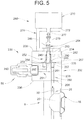
- Degassing system 300 includes a support member 304 having a first mounting surface 307 coupled to head portion 8 and a second mounting surface 308.
- Support member 304 also includes an outlet 311 that receives discharge fitting 56 and a check valve receiving portion 314 that houses valve seat 62.
- Support member 304 is further shown to include a first passage 317 and a second passage 318.
- First passage 317 includes a first end 320 that extends from first mounting surface 307 to a second end 321.
- Second passage 318 includes a first end portion 323 that extends from and is fluidically connected with an intermediate portion (not separately labeled) to a second end portion 324 that fluidically connects with outlet 311.
- a check valve actuator 329 is attached to support member 304 at second mounting surface 308.
- Check valve actuator 329 is shown in the form of an electro-magnetic actuator 331.
- Electro-magnetic actuator 331 takes the form of a solenoid 333 having a coil 334.
- Coil 334 is configured to generate an electro-motive force that acts upon a plunger 336.
- Plunger 336 includes an integral check valve 338 that takes the form of a check ball 340.
- Plunger 336 and check ball 340 return to a ready position under force of gravity. With this arrangement, check ball 340 responds to pressure changes within pump chamber 20 to allow fluid to flow from flow path 30, through first and second passages 317 and 318, and pass through discharge fitting 56.
- Check ball 340 is also unseated when electro-magnetic actuator 331 is energized drawing plunger 336 toward coil 334 to selectively allow gases trapped within head portion 8 to pass through discharge fitting 56.
- Degassing system 350 includes a support member 354 having a first mounting surface 357 coupled to head portion 8 and a second mounting surface 358.
- Support member 354 also includes an outlet 360 that fluidically connects with discharge fitting 56 and a check valve receiving portion 362.
- Check valve receiving portion 362 is arranged adjacent to first mounting surface 357 and houses check valve 60 and valve seat 62.
- Support member 354 is further shown to include a first passage 364 and a second passage 365.
- First passage 364 includes a first end 367 that extends from and fluidically connects with check valve receiving portion 362 to a second end 368 that fluidically connects with outlet 360.
- Second passage 365 includes a first end portion 370 that extends from, and fluidically connects with, check valve receiving portion 362 to a second end portion 371 that is fluidically exposed at second mounting surface 358.
- a check valve actuator 375 is supported at second mounting surface 358.
- Check valve actuator 375 takes the form of a linear actuator 377.
- Linear actuator 377 is shown in the form of a solenoid 379 including a plunger 380 operatively connected to a reservoir member 381 coupled to second mounting surface 358.
- Reservoir member 381 includes a reservoir 383 and a diaphragm 387.
- Diaphragm 387 is connected to plunger 380.
- check valve 60 responds to changes in pressure in pump chamber 20. More specifically, check valve actuator 375 acts indirectly upon check valve 60.
- solenoid 379 is activated to shift plunger 380 causing diaphragm 387 to deliver a pulse of liquid through second passage 365. The pulse of liquid unseats check ball 60 from valve seat 62 allowing any trapped gases to pass through first passage 364 and out from discharge fitting 56.
- the exemplary embodiments provide a system for alleviating gas build up in a head portion of a diaphragm metering pump.
- the exemplary embodiments include an actuator that acts directly upon a discharge check valve or indirectly on the discharge check valve to allow built up gases to flow to through an outlet.
- the exemplary embodiments allow built up gases to flow through the pump outlet to the liquid destination.
- the exemplary embodiments eliminate the need for additional plumbing, valves or other hardware and also ensure that all liquid passing though the discharge is passed from the outlet.
- the exemplary embodiments may use various actuators, including pneumatic actuators, hydraulic actuators, electric actuators, or actuators that are not linear, to unseat the check valve allowing gases to pass from the outlet.
- check valve is shown and described as a check ball and a diaphragm valve
- other types of checking elements may be employed.
- the exemplary embodiments may employ poppet valves, flapper valves, reed valves, wafer type valves or other elements that may be employed to allow fluid flow through a passage in one direction and to check or arrest fluid flow through the passage in an opposing direction.
- the mounting brackets are described as being generally U-Shaped, other types of brackets including a wide range of geometries may be employed.
- the accumulation of gases may be sensed using various techniques/devices and check valves may be unseated to alleviate gas build up based on these techniques and/or signals from these devices or, alternatively, the check valve may be periodically unseated on a time basis.
Landscapes
- Engineering & Computer Science (AREA)
- Mechanical Engineering (AREA)
- General Engineering & Computer Science (AREA)
- Details Of Reciprocating Pumps (AREA)
- Reciprocating Pumps (AREA)
- Check Valves (AREA)
Claims (15)
- Membrandosierpumpe (2), umfassend:einen Pumpenkörper (4) mit einem Kopfabschnitt (8), der eine Saugseite (23) und eine Druckseite (25) aufweist, die einen Strömungspfad (30) von einer Fluidquelle (28) zu einem Fluidziel (32) definieren, wobei die Druckseite (25) einen Auslass (76) mit einem Ventilsitz (62), der auf der Druckseite angeordnet ist, und ein Rückschlagventil (58) umfasst, das auf dem Ventilsitz (62) angeordnet ist; undein Entgasungssystem (66) mit einem Rückschlagventilstellglied (96), das funktionell mit dem Rückschlagventil (58) verbunden ist, wobei das Rückschlagventilstellglied (96) selektiv aktiviert wird, um das Rückschlagventil (58) vom Ventilsitz (62) zu lösen, damit die im Kopfabschnitt (8) eingeschlossenen Gase durch die Auslassseite (25) gelangen können; undwobei die Gase und die gesamte Flüssigkeit, die durch die Auslassseite (25) strömen, von dem Auslass (76) zu dem Flüssigkeitsziel (32) geleitet werden.
- Membrandosierpumpe (2) nach Anspruch 1,wobei das Rückschlagventilstellglied (96) konfiguriert und angeordnet ist, um auf das Rückschlagventil (58) entlang einer im Wesentlichen parallel zum Strömungsweg verlaufenden Achse einzuwirken.
- Membrandosierpumpe (2) nach Anspruch 1, wobei das Rückschlagventilstellglied (96) konfiguriert und angeordnet ist, um auf das Rückschlagventil (58) entlang einer Achse einzuwirken, die sich in einem Winkel zum Strömungsweg erstreckt.
- Membrandosierpumpe (2) nach Anspruch 1, wobei das Rückschlagventilstellglied (96) konfiguriert und angeordnet ist, um auf das Rückschlagventil (58) entlang einer Achse einzuwirken, die mit dem Strömungsweg übereinstimmt.
- Membrandosierpumpe (2) nach Anspruch 1,wobei das Rückschlagventilstellglied (96) eine Magnetspule mit einem Kolben (107) umfasst.
- Membrandosierpumpe (2) nach Anspruch 5, wobei der Kolben (107) auf einen Stellgliedstift wirkt, der direkt auf das Rückschlagventil (58) wirkt.
- Membrandosierpumpe (2) nach Anspruch 5, wobei der Kolben (107) indirekt auf das Rückschlagventil (58) wirkt.
- Membrandosierpumpe (2) nach Anspruch 5, wobei das Rückschlagventil (58) integral mit dem Kolben (107) ausgebildet ist.
- Membrandosierpumpe (2) nach Anspruch 5, wobei das Rückschlagventil (58) lösbar mit dem Kolben (107) verbunden ist.
- Membrandosierpumpe (2) nach Anspruch 1,wobei das Rückschlagventil (58) eine Rückschlagkugel (60) umfasst.
- Membrandosierpumpe (2) nach Anspruch 1,wobei das Rückschlagventil (58) ein Membranventil (287) umfasst.
- Verfahren zum Entgasen einer Membrandosierpumpe, umfassend:Ansaugen einer Flüssigkeit aus einer Flüssigkeitsquelle durch eine Saugseite (23) einer Membrandosierpumpe (2);Leiten der Flüssigkeit von der Saugseite (23) in einen Kopfabschnitt (8) der Membrandosierpumpe (2);Führen der Flüssigkeit durch ein Rückschlagventil (58) vom Kopfabschnitt (8) zu einer Druckseite (25) der Membrandosierpumpe (2),wobei die Druckseite (25) einen Auslass mit einem Ventilsitz (62) und dem am Ventilsitz (62) angeordneten Rückschlagventil (58) umfasst.; undEinleiten eines Rückschlagventilstellglieds (96), um das Rückschlagventil (58) zu lösen, so dass im Kopfabschnitt (8) angesammelte Gase und die gesamte Flüssigkeit durch den Auslass an der Auslassseite (25) zu einem Flüssigkeitsziel gelangen.
- Verfahren nach Anspruch 12, ferner umfassend: Erfassen eines Parameters der von der Druckseite (25) der Membrandosierpumpe (2) strömenden Flüssigkeit, wobei das Rückschlagventilstellglied (96) als Reaktion auf den Parameter der von der Druckseite (25) der Pumpe (2) strömenden Flüssigkeit ausgelöst wird.
- Verfahren nach Anspruch 12, wobei das Rückschlagventilstellglied (96) als Reaktion auf das Verstreichen einer vorbestimmten Zeitspanne ausgelöst wird.
- Verfahren nach Anspruch 12, wobei das Auslösen des Rückschlagventilstellglieds (96) das Aktivieren eines Linearstellglieds mit einem Kolben (107) beinhaltet.
Applications Claiming Priority (2)
| Application Number | Priority Date | Filing Date | Title |
|---|---|---|---|
| US13/595,380 US20140056724A1 (en) | 2012-08-27 | 2012-08-27 | Diaphragm metering pump having a degassing system |
| PCT/US2013/056750 WO2014035938A1 (en) | 2012-08-27 | 2013-08-27 | Diaphragm metering pump having a degassing system |
Publications (2)
| Publication Number | Publication Date |
|---|---|
| EP2888477A1 EP2888477A1 (de) | 2015-07-01 |
| EP2888477B1 true EP2888477B1 (de) | 2019-11-13 |
Family
ID=49123927
Family Applications (1)
| Application Number | Title | Priority Date | Filing Date |
|---|---|---|---|
| EP13759634.2A Active EP2888477B1 (de) | 2012-08-27 | 2013-08-27 | Membrandosierpumpe mit einem entgasungssystem |
Country Status (7)
| Country | Link |
|---|---|
| US (1) | US20140056724A1 (de) |
| EP (1) | EP2888477B1 (de) |
| JP (1) | JP6316295B2 (de) |
| KR (1) | KR20150048837A (de) |
| CN (1) | CN104662295B (de) |
| BR (1) | BR112015003097A2 (de) |
| WO (1) | WO2014035938A1 (de) |
Families Citing this family (4)
| Publication number | Priority date | Publication date | Assignee | Title |
|---|---|---|---|---|
| JP2521724B2 (ja) | 1986-08-29 | 1996-08-07 | 日産自動車株式会社 | ステアリングロツク装置 |
| US10876527B2 (en) * | 2015-06-22 | 2020-12-29 | Seko S.P.A. | Bleed valve and self-bleeding pump provided with such valve |
| JP6177850B2 (ja) * | 2015-09-17 | 2017-08-09 | 株式会社オーヤラックス | ポンプ装置 |
| KR200492927Y1 (ko) | 2020-06-30 | 2021-01-05 | 이에스피 주식회사 | 정량펌프용 탈가스 챔버 |
Family Cites Families (17)
| Publication number | Priority date | Publication date | Assignee | Title |
|---|---|---|---|---|
| US2648291A (en) * | 1949-10-01 | 1953-08-11 | Clifford B Moller | Water purification unit |
| NL162720C (nl) * | 1968-10-08 | 1980-06-16 | Nikkiso Co Ltd | Pompsysteem. |
| DE2216215A1 (de) * | 1972-04-04 | 1973-10-18 | Ott Kg Lewa | Membranpumpe |
| DE2803470B2 (de) * | 1978-01-27 | 1980-06-04 | Dulger, Viktor, 6900 Heidelberg | Entlüftungsvorrichtung fur eine Flussigkeitskolbenpumpe, insbesondere Dosierpumpe |
| DE2803471C2 (de) * | 1978-01-27 | 1980-01-03 | Dulger, Viktor, 6900 Heidelberg | Dosierpumpenkopf |
| DE3631984C1 (de) * | 1986-09-19 | 1987-12-17 | Hans Ing Kern | Dosierpumpe |
| DE3928949A1 (de) * | 1989-08-31 | 1991-03-14 | Wagner Gmbh J | Membranpumpe |
| US5456581A (en) * | 1994-08-12 | 1995-10-10 | The United States Of America As Represented By The Secretary Of The Navy | Control system for a multi-piston pump with solenoid valves for the production of constant outlet pressure flow |
| DE4439962A1 (de) * | 1994-11-09 | 1996-05-15 | Lang Apparatebau Gmbh | Dosierpumpe mit Entlüftungseinrichtung |
| DE19712589C1 (de) * | 1997-03-26 | 1998-06-04 | Bosch Gmbh Robert | Brennstoffeinspritzventil und Verfahren zur Herstellung einer Ventilnadel eines Brennstoffeinspritzventils |
| US7213612B2 (en) * | 2000-03-16 | 2007-05-08 | Ross Operating Valve Company | High pressure ball-poppet control valve with flow control |
| US7175397B2 (en) * | 2002-09-27 | 2007-02-13 | Pulsafeeder, Inc. | Effervescent gas bleeder apparatus |
| JP2004122085A (ja) * | 2002-10-07 | 2004-04-22 | Asahi Sunac Corp | 塗装装置 |
| JP2010242764A (ja) * | 2003-06-17 | 2010-10-28 | Seiko Epson Corp | ポンプ |
| JP4694377B2 (ja) * | 2006-01-27 | 2011-06-08 | シーケーディ株式会社 | 薬液供給システム |
| JP2010077948A (ja) * | 2008-09-29 | 2010-04-08 | Seiko Epson Corp | 流体噴射装置、及び流体噴射装置の制御方法 |
| US9828986B2 (en) * | 2010-02-23 | 2017-11-28 | Artemis Intelligent Power Limited | Method of measuring a property of entrained gas in a hydraulic fluid and fluid-working machine |
-
2012
- 2012-08-27 US US13/595,380 patent/US20140056724A1/en not_active Abandoned
-
2013
- 2013-08-27 BR BR112015003097A patent/BR112015003097A2/pt not_active IP Right Cessation
- 2013-08-27 WO PCT/US2013/056750 patent/WO2014035938A1/en not_active Ceased
- 2013-08-27 CN CN201380044364.3A patent/CN104662295B/zh not_active Expired - Fee Related
- 2013-08-27 KR KR1020157007834A patent/KR20150048837A/ko not_active Ceased
- 2013-08-27 EP EP13759634.2A patent/EP2888477B1/de active Active
- 2013-08-27 JP JP2015529916A patent/JP6316295B2/ja not_active Expired - Fee Related
Non-Patent Citations (1)
| Title |
|---|
| None * |
Also Published As
| Publication number | Publication date |
|---|---|
| EP2888477A1 (de) | 2015-07-01 |
| JP6316295B2 (ja) | 2018-04-25 |
| CN104662295A (zh) | 2015-05-27 |
| US20140056724A1 (en) | 2014-02-27 |
| CN104662295B (zh) | 2018-09-04 |
| JP2015526651A (ja) | 2015-09-10 |
| KR20150048837A (ko) | 2015-05-07 |
| BR112015003097A2 (pt) | 2017-07-04 |
| WO2014035938A1 (en) | 2014-03-06 |
Similar Documents
| Publication | Publication Date | Title |
|---|---|---|
| EP1546557B1 (de) | Dosierpumpe mit gasentfernungsvorrichtung | |
| EP2888477B1 (de) | Membrandosierpumpe mit einem entgasungssystem | |
| JP5893163B2 (ja) | 弁 | |
| EP2143983A3 (de) | Ventil zur Flussratensteuerung | |
| JP5247298B2 (ja) | サックバックバルブ | |
| US6568926B1 (en) | Fluid metering pump | |
| US10094346B1 (en) | Fuel pump with an improved maximum-pressure valve for a direct-injection system | |
| CN110226029B (zh) | 具有可密封通气阀的正密封比例控制阀 | |
| US20200182673A1 (en) | Micrometering Pump | |
| EP2213381A1 (de) | Rücksaugventilsystem und verfahren zur steuerung des ventilschliessbetriebs | |
| RU2008136190A (ru) | Насосные системы доставки текучих сред и способы применения устройства приложения усилия | |
| JP2010106868A (ja) | 潤滑装置 | |
| JP2004535528A (ja) | スクリュー圧縮機 | |
| WO2016088340A1 (ja) | 高圧ポンプ | |
| CN110892263B (zh) | 柱塞泵 | |
| CN107587964B (zh) | 适于直喷系统的具有改进的最大压力阀的燃料泵 | |
| JP5123310B2 (ja) | ソレノイド駆動装置を有するダイアフラムポンプ内の能動型逆止弁 | |
| CN106795873B (zh) | 带有流体贮存器的容积泵 | |
| RU2161734C1 (ru) | Мембранный пневмоприводной насос | |
| US1659710A (en) | Means for resupplying air to water-distributing systems | |
| JP4483790B2 (ja) | レギュレートバルブ | |
| WO2010093852A1 (en) | Pilot protector for valve | |
| JP2007239896A (ja) | ダイヤフラム弁 |
Legal Events
| Date | Code | Title | Description |
|---|---|---|---|
| PUAI | Public reference made under article 153(3) epc to a published international application that has entered the european phase |
Free format text: ORIGINAL CODE: 0009012 |
|
| 17P | Request for examination filed |
Effective date: 20150225 |
|
| AK | Designated contracting states |
Kind code of ref document: A1 Designated state(s): AL AT BE BG CH CY CZ DE DK EE ES FI FR GB GR HR HU IE IS IT LI LT LU LV MC MK MT NL NO PL PT RO RS SE SI SK SM TR |
|
| AX | Request for extension of the european patent |
Extension state: BA ME |
|
| DAX | Request for extension of the european patent (deleted) | ||
| STAA | Information on the status of an ep patent application or granted ep patent |
Free format text: STATUS: EXAMINATION IS IN PROGRESS |
|
| 17Q | First examination report despatched |
Effective date: 20181106 |
|
| GRAP | Despatch of communication of intention to grant a patent |
Free format text: ORIGINAL CODE: EPIDOSNIGR1 |
|
| STAA | Information on the status of an ep patent application or granted ep patent |
Free format text: STATUS: GRANT OF PATENT IS INTENDED |
|
| INTG | Intention to grant announced |
Effective date: 20190605 |
|
| GRAS | Grant fee paid |
Free format text: ORIGINAL CODE: EPIDOSNIGR3 |
|
| GRAA | (expected) grant |
Free format text: ORIGINAL CODE: 0009210 |
|
| STAA | Information on the status of an ep patent application or granted ep patent |
Free format text: STATUS: THE PATENT HAS BEEN GRANTED |
|
| AK | Designated contracting states |
Kind code of ref document: B1 Designated state(s): AL AT BE BG CH CY CZ DE DK EE ES FI FR GB GR HR HU IE IS IT LI LT LU LV MC MK MT NL NO PL PT RO RS SE SI SK SM TR |
|
| REG | Reference to a national code |
Ref country code: CH Ref legal event code: EP Ref country code: AT Ref legal event code: REF Ref document number: 1201926 Country of ref document: AT Kind code of ref document: T Effective date: 20191115 |
|
| REG | Reference to a national code |
Ref country code: DE Ref legal event code: R096 Ref document number: 602013062875 Country of ref document: DE |
|
| REG | Reference to a national code |
Ref country code: IE Ref legal event code: FG4D |
|
| REG | Reference to a national code |
Ref country code: NL Ref legal event code: MP Effective date: 20191113 |
|
| REG | Reference to a national code |
Ref country code: LT Ref legal event code: MG4D |
|
| PG25 | Lapsed in a contracting state [announced via postgrant information from national office to epo] |
Ref country code: FI Free format text: LAPSE BECAUSE OF FAILURE TO SUBMIT A TRANSLATION OF THE DESCRIPTION OR TO PAY THE FEE WITHIN THE PRESCRIBED TIME-LIMIT Effective date: 20191113 Ref country code: BG Free format text: LAPSE BECAUSE OF FAILURE TO SUBMIT A TRANSLATION OF THE DESCRIPTION OR TO PAY THE FEE WITHIN THE PRESCRIBED TIME-LIMIT Effective date: 20200213 Ref country code: PT Free format text: LAPSE BECAUSE OF FAILURE TO SUBMIT A TRANSLATION OF THE DESCRIPTION OR TO PAY THE FEE WITHIN THE PRESCRIBED TIME-LIMIT Effective date: 20200313 Ref country code: GR Free format text: LAPSE BECAUSE OF FAILURE TO SUBMIT A TRANSLATION OF THE DESCRIPTION OR TO PAY THE FEE WITHIN THE PRESCRIBED TIME-LIMIT Effective date: 20200214 Ref country code: PL Free format text: LAPSE BECAUSE OF FAILURE TO SUBMIT A TRANSLATION OF THE DESCRIPTION OR TO PAY THE FEE WITHIN THE PRESCRIBED TIME-LIMIT Effective date: 20191113 Ref country code: NO Free format text: LAPSE BECAUSE OF FAILURE TO SUBMIT A TRANSLATION OF THE DESCRIPTION OR TO PAY THE FEE WITHIN THE PRESCRIBED TIME-LIMIT Effective date: 20200213 Ref country code: LV Free format text: LAPSE BECAUSE OF FAILURE TO SUBMIT A TRANSLATION OF THE DESCRIPTION OR TO PAY THE FEE WITHIN THE PRESCRIBED TIME-LIMIT Effective date: 20191113 Ref country code: SE Free format text: LAPSE BECAUSE OF FAILURE TO SUBMIT A TRANSLATION OF THE DESCRIPTION OR TO PAY THE FEE WITHIN THE PRESCRIBED TIME-LIMIT Effective date: 20191113 Ref country code: NL Free format text: LAPSE BECAUSE OF FAILURE TO SUBMIT A TRANSLATION OF THE DESCRIPTION OR TO PAY THE FEE WITHIN THE PRESCRIBED TIME-LIMIT Effective date: 20191113 Ref country code: ES Free format text: LAPSE BECAUSE OF FAILURE TO SUBMIT A TRANSLATION OF THE DESCRIPTION OR TO PAY THE FEE WITHIN THE PRESCRIBED TIME-LIMIT Effective date: 20191113 Ref country code: LT Free format text: LAPSE BECAUSE OF FAILURE TO SUBMIT A TRANSLATION OF THE DESCRIPTION OR TO PAY THE FEE WITHIN THE PRESCRIBED TIME-LIMIT Effective date: 20191113 |
|
| PG25 | Lapsed in a contracting state [announced via postgrant information from national office to epo] |
Ref country code: IS Free format text: LAPSE BECAUSE OF FAILURE TO SUBMIT A TRANSLATION OF THE DESCRIPTION OR TO PAY THE FEE WITHIN THE PRESCRIBED TIME-LIMIT Effective date: 20200313 Ref country code: HR Free format text: LAPSE BECAUSE OF FAILURE TO SUBMIT A TRANSLATION OF THE DESCRIPTION OR TO PAY THE FEE WITHIN THE PRESCRIBED TIME-LIMIT Effective date: 20191113 Ref country code: RS Free format text: LAPSE BECAUSE OF FAILURE TO SUBMIT A TRANSLATION OF THE DESCRIPTION OR TO PAY THE FEE WITHIN THE PRESCRIBED TIME-LIMIT Effective date: 20191113 |
|
| PG25 | Lapsed in a contracting state [announced via postgrant information from national office to epo] |
Ref country code: AL Free format text: LAPSE BECAUSE OF FAILURE TO SUBMIT A TRANSLATION OF THE DESCRIPTION OR TO PAY THE FEE WITHIN THE PRESCRIBED TIME-LIMIT Effective date: 20191113 |
|
| PG25 | Lapsed in a contracting state [announced via postgrant information from national office to epo] |
Ref country code: DK Free format text: LAPSE BECAUSE OF FAILURE TO SUBMIT A TRANSLATION OF THE DESCRIPTION OR TO PAY THE FEE WITHIN THE PRESCRIBED TIME-LIMIT Effective date: 20191113 Ref country code: EE Free format text: LAPSE BECAUSE OF FAILURE TO SUBMIT A TRANSLATION OF THE DESCRIPTION OR TO PAY THE FEE WITHIN THE PRESCRIBED TIME-LIMIT Effective date: 20191113 Ref country code: RO Free format text: LAPSE BECAUSE OF FAILURE TO SUBMIT A TRANSLATION OF THE DESCRIPTION OR TO PAY THE FEE WITHIN THE PRESCRIBED TIME-LIMIT Effective date: 20191113 Ref country code: CZ Free format text: LAPSE BECAUSE OF FAILURE TO SUBMIT A TRANSLATION OF THE DESCRIPTION OR TO PAY THE FEE WITHIN THE PRESCRIBED TIME-LIMIT Effective date: 20191113 |
|
| REG | Reference to a national code |
Ref country code: DE Ref legal event code: R097 Ref document number: 602013062875 Country of ref document: DE |
|
| REG | Reference to a national code |
Ref country code: AT Ref legal event code: MK05 Ref document number: 1201926 Country of ref document: AT Kind code of ref document: T Effective date: 20191113 |
|
| PG25 | Lapsed in a contracting state [announced via postgrant information from national office to epo] |
Ref country code: SM Free format text: LAPSE BECAUSE OF FAILURE TO SUBMIT A TRANSLATION OF THE DESCRIPTION OR TO PAY THE FEE WITHIN THE PRESCRIBED TIME-LIMIT Effective date: 20191113 Ref country code: SK Free format text: LAPSE BECAUSE OF FAILURE TO SUBMIT A TRANSLATION OF THE DESCRIPTION OR TO PAY THE FEE WITHIN THE PRESCRIBED TIME-LIMIT Effective date: 20191113 |
|
| PLBE | No opposition filed within time limit |
Free format text: ORIGINAL CODE: 0009261 |
|
| STAA | Information on the status of an ep patent application or granted ep patent |
Free format text: STATUS: NO OPPOSITION FILED WITHIN TIME LIMIT |
|
| 26N | No opposition filed |
Effective date: 20200814 |
|
| PGFP | Annual fee paid to national office [announced via postgrant information from national office to epo] |
Ref country code: LU Payment date: 20200727 Year of fee payment: 8 Ref country code: MC Payment date: 20200724 Year of fee payment: 8 Ref country code: IE Payment date: 20200723 Year of fee payment: 8 |
|
| PG25 | Lapsed in a contracting state [announced via postgrant information from national office to epo] |
Ref country code: AT Free format text: LAPSE BECAUSE OF FAILURE TO SUBMIT A TRANSLATION OF THE DESCRIPTION OR TO PAY THE FEE WITHIN THE PRESCRIBED TIME-LIMIT Effective date: 20191113 Ref country code: SI Free format text: LAPSE BECAUSE OF FAILURE TO SUBMIT A TRANSLATION OF THE DESCRIPTION OR TO PAY THE FEE WITHIN THE PRESCRIBED TIME-LIMIT Effective date: 20191113 |
|
| PGFP | Annual fee paid to national office [announced via postgrant information from national office to epo] |
Ref country code: CH Payment date: 20200724 Year of fee payment: 8 Ref country code: BE Payment date: 20200724 Year of fee payment: 8 |
|
| PG25 | Lapsed in a contracting state [announced via postgrant information from national office to epo] |
Ref country code: IT Free format text: LAPSE BECAUSE OF FAILURE TO SUBMIT A TRANSLATION OF THE DESCRIPTION OR TO PAY THE FEE WITHIN THE PRESCRIBED TIME-LIMIT Effective date: 20191113 |
|
| REG | Reference to a national code |
Ref country code: DE Ref legal event code: R082 Ref document number: 602013062875 Country of ref document: DE Representative=s name: MURGITROYD GERMANY PATENTANWALTSGESELLSCHAFT M, DE Ref country code: DE Ref legal event code: R082 Ref document number: 602013062875 Country of ref document: DE Representative=s name: MURGITROYD & COMPANY, DE |
|
| PGFP | Annual fee paid to national office [announced via postgrant information from national office to epo] |
Ref country code: FR Payment date: 20210729 Year of fee payment: 9 |
|
| PGFP | Annual fee paid to national office [announced via postgrant information from national office to epo] |
Ref country code: GB Payment date: 20210804 Year of fee payment: 9 Ref country code: DE Payment date: 20210720 Year of fee payment: 9 |
|
| REG | Reference to a national code |
Ref country code: CH Ref legal event code: PL |
|
| PG25 | Lapsed in a contracting state [announced via postgrant information from national office to epo] |
Ref country code: MC Free format text: LAPSE BECAUSE OF NON-PAYMENT OF DUE FEES Effective date: 20210831 |
|
| REG | Reference to a national code |
Ref country code: BE Ref legal event code: MM Effective date: 20210831 |
|
| PG25 | Lapsed in a contracting state [announced via postgrant information from national office to epo] |
Ref country code: LI Free format text: LAPSE BECAUSE OF NON-PAYMENT OF DUE FEES Effective date: 20210831 Ref country code: CH Free format text: LAPSE BECAUSE OF NON-PAYMENT OF DUE FEES Effective date: 20210831 |
|
| PG25 | Lapsed in a contracting state [announced via postgrant information from national office to epo] |
Ref country code: TR Free format text: LAPSE BECAUSE OF FAILURE TO SUBMIT A TRANSLATION OF THE DESCRIPTION OR TO PAY THE FEE WITHIN THE PRESCRIBED TIME-LIMIT Effective date: 20191113 Ref country code: MT Free format text: LAPSE BECAUSE OF FAILURE TO SUBMIT A TRANSLATION OF THE DESCRIPTION OR TO PAY THE FEE WITHIN THE PRESCRIBED TIME-LIMIT Effective date: 20191113 Ref country code: LU Free format text: LAPSE BECAUSE OF NON-PAYMENT OF DUE FEES Effective date: 20210827 Ref country code: CY Free format text: LAPSE BECAUSE OF FAILURE TO SUBMIT A TRANSLATION OF THE DESCRIPTION OR TO PAY THE FEE WITHIN THE PRESCRIBED TIME-LIMIT Effective date: 20191113 |
|
| PG25 | Lapsed in a contracting state [announced via postgrant information from national office to epo] |
Ref country code: MK Free format text: LAPSE BECAUSE OF FAILURE TO SUBMIT A TRANSLATION OF THE DESCRIPTION OR TO PAY THE FEE WITHIN THE PRESCRIBED TIME-LIMIT Effective date: 20191113 |
|
| PG25 | Lapsed in a contracting state [announced via postgrant information from national office to epo] |
Ref country code: IE Free format text: LAPSE BECAUSE OF NON-PAYMENT OF DUE FEES Effective date: 20210827 Ref country code: BE Free format text: LAPSE BECAUSE OF NON-PAYMENT OF DUE FEES Effective date: 20210831 |
|
| REG | Reference to a national code |
Ref country code: DE Ref legal event code: R119 Ref document number: 602013062875 Country of ref document: DE |
|
| GBPC | Gb: european patent ceased through non-payment of renewal fee |
Effective date: 20220827 |
|
| PG25 | Lapsed in a contracting state [announced via postgrant information from national office to epo] |
Ref country code: FR Free format text: LAPSE BECAUSE OF NON-PAYMENT OF DUE FEES Effective date: 20220831 Ref country code: DE Free format text: LAPSE BECAUSE OF NON-PAYMENT OF DUE FEES Effective date: 20230301 |
|
| PG25 | Lapsed in a contracting state [announced via postgrant information from national office to epo] |
Ref country code: GB Free format text: LAPSE BECAUSE OF NON-PAYMENT OF DUE FEES Effective date: 20220827 |