EP2887658A2 - Projektionsvorrichtung, geometrisches Korrekturanpassungsverfahren und Programm zur geometrischen Korrekturanpassung - Google Patents
Projektionsvorrichtung, geometrisches Korrekturanpassungsverfahren und Programm zur geometrischen Korrekturanpassung Download PDFInfo
- Publication number
- EP2887658A2 EP2887658A2 EP14198184.5A EP14198184A EP2887658A2 EP 2887658 A2 EP2887658 A2 EP 2887658A2 EP 14198184 A EP14198184 A EP 14198184A EP 2887658 A2 EP2887658 A2 EP 2887658A2
- Authority
- EP
- European Patent Office
- Prior art keywords
- element region
- projection
- region
- geometric correction
- vertex
- Prior art date
- Legal status (The legal status is an assumption and is not a legal conclusion. Google has not performed a legal analysis and makes no representation as to the accuracy of the status listed.)
- Granted
Links
Images






Classifications
-
- H—ELECTRICITY
- H04—ELECTRIC COMMUNICATION TECHNIQUE
- H04N—PICTORIAL COMMUNICATION, e.g. TELEVISION
- H04N9/00—Details of colour television systems
- H04N9/12—Picture reproducers
- H04N9/31—Projection devices for colour picture display, e.g. using electronic spatial light modulators [ESLM]
- H04N9/3179—Video signal processing therefor
- H04N9/3185—Geometric adjustment, e.g. keystone or convergence
Definitions
- the present invention relates to a projection apparatus, a geometric correction adjustment method, and a program for geometric correction adjustment.
- a projector has been known as an image projection apparatus that projects an image on a projection target object, such as a screen based on image data output from, for example, a personal computer.
- a projection region of the projector is adjusted with respect to the projection target object, such as the screen.
- Jpn. Pat. Appln. KOKAI publication No. 2006-227441 discloses a technology of shifting a vertex of the projection region by moving a cursor to transform a projection region and consequently performing adjustment of geometric correction.
- an object of the present invention is to provide a projection apparatus, a geometric correction adjustment method, and a program for geometric correction adjustment for easy adjustment of geometric correction.
- a projection apparatus includes a projection optical system configured to project projection light on a projection target object; an output display element having an element region including a plurality of pixels that modulate the projection light and configured to generate a projection image configured to be projected on the projection target object based on an input image by a quadrangular effective element region included in the element region; an operation unit configured to acquire an adjustment instruction from a user to adjust the effective element region in the element region; a geometric correction adjustment unit configured to transform the effective element region in the element region to shift a vertex of the effective element region along at least one side of two sides, each of the two sides having one end that is the vertex to be shifted, according to the adjustment instruction input to the operation unit; and a geometric correction unit configured to perform an operation of projecting the input image on the effective element region.
- a geometric correction adjustment method is a method for adjusting an effective element region in an element region in a projection apparatus, the projection apparatus including an output display element which has the element region including a plurality of pixels that modulate projection light and generates a projection image configured to be projected on a projection target object based on an input image by the quadrangular effective element region included in the element region, and projecting the projection image to the projection target object.
- the geometric correction adjustment method includes acquiring an adjustment instruction from a user to adjust the effective element region in the element region; and transforming the effective element region in the element region to shift a vertex of the effective element region along at least one side of two sides, each of the sides having one end that is the vertex to be shifted, according to the adjustment instruction.
- a program for geometric correction adjustment causes a computer to perform geometric correction adjustment of adjusting an effective element region in an element region in a projection apparatus, the projection apparatus including an output display element which has the element region including a plurality of pixels that modulate projection light and generates a projection image configured to be projected on a projection target object based on an input image by the quadrangular effective element region included in the element region, and projecting the projection image to the projection target object.
- the program includes codes for: acquiring an adjustment instruction from a user to adjust the effective element region in the element region; and transforming the effective element region in the element region to shift a vertex of the effective element region along at least one side of two sides, each of the sides having one end that is the vertex to be shifted, according to the adjustment instruction.
- a projection apparatus a geometric correction adjustment method, and a program for geometric correction adjustment for easy adjustment of geometric correction are provided.
- a projection apparatus employs a digital light processing (DLP) (registered trademark) using a micromirror display device.
- DLP digital light processing
- FIG. 1 A schematic configuration of a projector 1 is illustrated in FIG. 1 , as a projection apparatus according to the present embodiment.
- the projector 1 includes an input/output connector unit 11, an input/output interface (I/F) 12, an image transformation unit 13, a projection processing unit 14, a micromirror element 15, a light source unit 16, a mirror 18, a projection lens 20, a CPU 25, a main memory 26, a program memory 27, an operation unit 28, a sound processing unit 30, a speaker 32, and a system bus SB.
- the input/output connector unit 11 includes, for example, a pin-jack (RCA) type video input terminal or a D-sub15 type RGB input terminal installed therein and receives an analog image signal.
- the received image signal is input to the image transformation unit 13 through the input/output I/F 12 and the system bus SB.
- the input analog image signal of any of various standards is converted to a digital image signal in the input/output I/F 12.
- the input/output connector unit 11 includes, for example, an HDMI (registered trademark) terminal installed therein, and may receive not only the analog image signal, but also a digital image signal. Also, the input/output connector unit 11 receives a sound signal by an analog signal or a digital signal.
- the received sound signal is input to the sound processing unit 30 through the input/output I/F 12 and the system bus SB.
- the image transformation unit 13 may be called a scaler.
- the image transformation unit 13 performs conversion to adjust a resolution value, a gradation value or the like on input image data and generates image data having a predetermined format suitable for projection.
- the image transformation unit 13 includes a geometric correction adjustment unit 13a and a geometric correction unit 13b which receives an instruction from the geometric correction adjustment unit 13a and performs image correction, which are described below.
- the image transformation unit 13 transmits the image data that is converted by, for example, the image correction, to the projection processing unit 14. If required, the image transformation unit 13 transmits image data, on which symbols for on screen display (OSD) indicating various operational states of the projector 1 are superimposed, to the projection processing unit 14, as processed image data.
- OSD on screen display
- the light source unit 16 emits a plurality of color light beams including primary color light beams of red (R), green (G), and blue (B).
- the light source unit 16 is configured to sequentially emit the plurality of color light beams in a time division manner. Light emitted by the light source unit 16 is totally reflected by the mirror 18 and is incident on the micromirror element 15.
- the micromirror element 15 includes a plurality of micromirrors arranged in an array form.
- the respective micromirrors are turned on/off at high speed to reflect the light irradiated from the light source unit 16 in a direction of the projection lens 20 or to deflect the light from a direction of the projection lens 20.
- the micromirrors are arranged in, for example, a wide extended graphic array (WXGA) (1,280 pixels x 800 pixels).
- WXGA wide extended graphic array
- the micromirror element 15 forms an image having, for example, the WXGA resolution, by reflection of the respective micromirrors. That is, the micromirror element 15 functions as a spatial light modulation element.
- a region, in which a micromirror is arranged and which has a function of forming an image is referred to as an element region.
- the projection processing unit 14 operates the micromirror element 15 in order to display an image represented by the image data, according to the image data transmitted from the image transformation unit 13. That is, the projection processing unit 14 turns on/off the respective micromirrors of the micromirror element 15.
- the projection processing unit 14 drives the micromirror element 15 in a time division manner at high speed.
- the number of divisions of unit time is a number obtained by multiplying a frame rate according to a predetermined format, for example, 60 [frame/second], the number of divisions of color components, and the number of display gradations.
- the projection processing unit 14 synchronizes operation of the light source unit 16 with operation of the light source unit 16 to control the operation of the light source unit 16. That is, the projection processing unit 14 performs time division on each frame, and controls the operation of the light source unit 16 to sequentially emit light beams of all color components for each frame.
- the projection lens 20 adjusts the light guided from the micromirror element 15 to light to be projected on a projection target object, for example, a screen (not illustrated) or the like.
- a projection target object for example, a screen (not illustrated) or the like.
- an optical image formed by the light reflected by the micromirror element 15 is projected and displayed on a projection target object, such as a screen, through the projection lens 20.
- the projection lens 20 includes a zoom mechanism and has a function of changing a size of a projected image.
- the projection lens 20 includes a focus adjustment mechanism for adjusting a focus of the projected image.
- the light source unit 16, the projection lens 20, and the like function as a projection optical system configured to project projection light on the projection target object.
- the sound processing unit 30 includes a sound source circuit such as a PCM sound source.
- the sound processing unit 30 drives the speaker 32 to amplify and emit sound, based on analog sound data input from the input/output connector unit 11, or based on a signal obtained by converting, to analog signals, digital sound data provided upon projection operation. Also, the sound processing unit 30 generates a beep sound or the like if required.
- the speaker 32 is a general speaker that emits sound based on a signal input from the sound processing unit 30.
- the CPU 25 controls operations of the image transformation unit 13, the projection processing unit 14, and the sound processing unit 30.
- the CPU 25 is connected to the main memory 26 and the program memory 27.
- the main memory 26 is configured by, for example, an SRAM.
- the main memory 26 functions as a work memory of the CPU 25.
- the program memory 27 is configured by an electrically rewritable non-volatile memory.
- the program memory 27 stores an operation program to be performed by the CPU 25, a variety of format data, or the like.
- the CPU 25 is connected to the operation unit 28.
- the operation unit 28 includes a key operation unit which is installed in a body of the projector 1 and an infrared light receiving unit which receives infrared light from a remote control (not illustrated) dedicated to the projector 1.
- the operation unit 28 outputs a key operation signal to the CPU 25 based on a key operated by a user using the key operation unit of the body or the remote control.
- the CPU 25 controls operations of the respective units of the projector 1 in response to an instruction of the user from the operation unit 28, by using a program or data stored in the main memory 26 and the program memory 27.
- the operation unit 28 includes, for example, a cross key, an OK button, or the like.
- the geometric correction adjustment unit 13a of the image transformation unit 13 performs processing (processing illustrated in FIGS. 4A and 4B ) according to geometric correction (distortion correction) so as to express an image projected by projection light emitted from the projection lens 20 on a projection target object, without distortion. Specifically, the geometric correction adjustment unit 13a adjusts an image transformation parameter associated with geometric correction that is performed by the geometric correction unit 13b of the image transformation unit 13, based on an adjustment instruction of the user that is input from the operation unit 28, upon adjustment of geometric correction before projection of the input image is started. The geometric correction adjustment unit 13a outputs the adjusted image transformation parameter to the geometric correction unit 13b of the image transformation unit 13.
- the projection operation is performed by the projection processing unit 14 under the control of the CPU 25.
- the operation of the light source unit 16 is controlled by the projection processing unit 14.
- the projection processing unit 14 cause the light source unit 16 to sequentially emit three color light beams of, for example, a red light beam (R), a green light beam (G), and a blue light beam (B) by turning on/off respective color-emitting laser diodes or LEDs of the light source unit 16 or by changing a combination of light sources and phosphors.
- the projection processing unit 14 makes the red light beam, the green light beam, and the blue light beam incident on the micromirror element 15 from the light source unit 16 sequentially.
- the micromirror element 15 is operated such that, as a gradation increases, a time required to guide the incident light to the projection lens 20 increases, and as a gradation decreases, a time required to guide the incident light to the projection lens 20 decreases, based on the image data for each micromirror (each pixel) in each color light beam. That is, the projection processing unit 14 controls the micromirror element 15 such that a micromirror corresponding to a high-gradation pixel is in an on state for a long time, and a micromirror corresponding to a low-gradation pixel is in an off state for a long time. Therefore, with respect to light emitted from the projection lens 20, a gradation of each color can be expressed for each micromirror (each pixel).
- a color image is expressed by combining gradations, each of which is expressed by a turn-on time, for each color.
- projection light by which an image is expressed is projected from the projection lens 20.
- the projection light is projected on, for example, the screen and the color image is displayed on the screen or the like.
- a projector may be configured to form an image by combining light beams of complementary colors, such as magenta or yellow, and a white light beam and to emit light of such a color.
- FIG. 2A is a view schematically illustrating the micromirror element 15.
- a rectangle that is an outline schematically indicates an element region 62.
- the element region 62 is a region capable of expressing an image in which micromirrors are arranged in the micromirror element 15.
- a hatched rectangle in FIG. 2A schematically indicates an effective element region 64.
- the effective element region 64 is a region used to realize an image transformed by the image transformation unit 13, in the element region 62.
- a region outside the effective element region 64 is image-processed, with a pixel gradation being set to 0 (black).
- FIG. 2A schematically illustrates a case where the entire element region 62 is used to express an image as the effective element region 64.
- Grids of the effective element region 64 are given for convenience such that an image distortion is easily recognized. That is, although the element region 62 is described as being identical to the effective element region in FIG. 2A , the element region 62 is illustrated as being slightly larger than the effective element region 64 for ease of understanding.
- a case in which an optical axis of the projection lens 20 of the projector 1 is not perpendicular to the screen is considered.
- FIG. 2B schematically illustrates an appearance of a screen in the case where the entire element region 62 is used to express an image as the effective element region 64, as illustrated in FIG. 2A .
- a rectangle illustrated at an inner side schematically represents a projection target region 72 that is a rectangular screen.
- a hatched quadrangle represents a projection region 74 on which an image is projected by the projector 1.
- the projection region 74 is a quadrangle, not a rectangle. Grids of the projection region 74 are given for convenience such that an image distortion is easily recognized.
- the projector 1 is disposed such that an outline of the projection region 74 is located outside the projection target region 72 (the projection region 74 includes the entire projection target region 72) as illustrated in FIG. 2B , and optical characteristics of the projection lens 20 (optical zoom setting or the like) are set.
- the projection region 74 is not a rectangle, and the projected image is distorted.
- image expression using the micromirror element 15 is adjusted such that a rectangular image is projected on the projection target region 72 without distortion. That is, the image expressed on the element region 62 of the micromirror element 15 is a distorted image in which geometric correction is to be performed on an image to be projected, and consequently, adjustment is performed such that the image is projected on a projection target object without distortion.
- geometric correction is performed such that a size of a projected image is appropriately reduced, and an image gradation is set to 0 (black) with respect to a region outside the reduced image (a region outside the effective element region 64 in the element region 62).
- the geometric correction is performed by the geometric correction unit 13b of the image transformation unit 13.
- FIG. 3A schematically illustrates a relationship between the element region 62 and the effective element region 64 after geometric correction is performed by the geometric correction unit 13b of the image transformation unit 13.
- a distorted quadrangle in the element region is used for image expression as the effective element region 64.
- a projected image is appropriately reduced, and a region outside the effective element region 64 in the element region 62 is set to have an image gradation of 0 (black).
- FIG. 3B A relationship between the projection region 74 and the projection target region 72 of this case is schematically illustrated in FIG. 3B .
- the effective element region 64 as in FIG. 3A is set, and therefore, an image is projected on the projection target object without distortion.
- the image that is appropriately reduced in the effective element region 64 is projected to be placed within the projection region 74, and an image having a pixel gradation of 0 (black) is projected on a region portion (indicated by a dotted line) corresponding to the element region 62 outside the projection region 74.
- Adjusting the image in the element region 62 so as to project the image on the projection target object without distortion is referred to as geometric correction.
- the micromirror element 15 has an element region including a plurality of pixels that modulate projection light, and functions as an output display element that generates a projection image which is projected on the projection target object based on an input image by a quadrangular effective element region included within the element region.
- a method of setting an effective element region 64 required to project an image on a projection target object without distortion upon geometric correction according to the present embodiment will be described.
- a process associated with adjustment of geometric correction to be performed by the geometric correction adjustment unit 13a will be described with reference to flowcharts illustrated in FIGS. 4A and 4B .
- the user installs the projector 1 to adjust a distance of the projector 1 to a screen, and adjusts a focal distance, a focus, or the like of the projection lens 20 such that the projection region 74 is wider than the projection target region 72 of the projection target object that is, for example, a screen.
- the user inputs an instruction to start adjustment of geometric correction to the projector 1. The input is achieved, for example, when the user presses a button included on the operation unit 28 to start adjustment of geometric correction.
- step S2 the geometric correction adjustment unit 13a determines whether a user inputs an instruction to start adjustment of geometric correction. When it is determined that the instruction to start adjustment is not input, the processing returns to step S2 and waits for an input of the instruction to start adjustment. When it is determined that the instruction to start adjustment is input, the processing proceeds to step S3.
- step S3 the geometric correction adjustment unit 13a starts horizontal-direction adjustment processing of an upper left vertex.
- a user presses, for example, a left button or right button of a cross key of the operation unit 28.
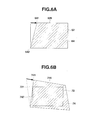
- the geometric correction adjustment unit 13a performs adjustment of image transformation that is performed by the geometric correction unit 13b on an image represented by using the micromirror element 15. That is, when the user presses the right button, the geometric correction adjustment unit 13a shifts an upper left corner 641 of the effective element region 64 to the right along an upper side 626 of the element region 62 to transform the effective element region 64 to have a trapezoid shape, as illustrated in FIG. 6A .
- an upper left corner 741 of the projection region 74 is shifted to the right along an upper side 746 of the projection region 74 and the shape of the projection region 74 is changed.
- the effective element region 64 is adjusted such that the upper left corner 741 of the projection region 74 is shifted to the left along the upper side 746 of the projection region 74.
- the user operates the left/right button of the operation unit 28 such that a left side 747 of the projection region 74 comes into contact with an upper left corner 721 of the projection target region 72.
- the user presses the OK button of the operation unit 28 when the left side 747 of the projection region 74 comes into contact with the upper left corner 721 of the projection target region 72.
- the OK button of the operation unit 28 is pressed, the horizontal-direction adjustment processing of the upper left vertex is ended. Subsequently, the processing proceeds to step S4.
- step S4 the geometric correction adjustment unit 13a starts vertical-direction adjustment processing of the upper left vertex.
- the user presses, for example, the up button or down button of the cross key of the operation unit 28.
- the geometric correction adjustment unit 13a performs adjustment of image transformation that is performed by the geometric correction unit 13b on an image represented by using the micromirror element 15. That is, when the user presses the down button, the geometric correction adjustment unit 13a shifts the upper left corner 641 of the effective element region 64 downward along the left side 647 of the effective element region 64 to transform the effective element region 64, as illustrated in FIG. 7A . In this case, as illustrated in FIG.
- the upper left corner 741 of the projection region 74 is shifted downward along the left side 747 of the projection region 74 and the shape of the projection region 74 is changed.
- the effective element region 64 is adjusted such that the upper left corner 741 of the projection region 74 is shifted upward along the left side 747 of the projection region 74.
- the user operates the up/down button of the operation unit 28 such that the upper left corner 741 of the projection region 74 is matched with the upper left corner 721 of the projection target region 72. While checking the projection region 74, the user presses the OK button of the operation unit 28 when the upper left corner 741 of the projection region 74 is matched with the upper left corner 721 of the projection target region 72. When the OK button of the operation unit 28 is pressed, the vertical-direction adjustment processing of an upper left vertex is ended.
- step S4 The vertical-direction adjustment processing of the upper left vertex (step S4) will be described in detail with reference to a flowchart of FIG. 4B .
- step S21 the geometric correction adjustment unit 13a calculates a function representing the left side 647 of the effective element region 64. Specifically, a function of a straight line passing through the upper left corner 641 and the lower left corner 642 in FIG. 6A is acquired.
- step S22 the geometric correction adjustment unit 13a acquires an instruction of the user which is input to the operation unit 28.
- step S23 the geometric correction adjustment unit 13a determines whether an input of the user acquired in step S22 is a press on the down button. When there is a press on the down button, the processing proceeds to step S24.
- step S24 the geometric correction adjustment unit 13a performs an operation of shifting the upper left corner 641 of the effective element region 64 downward along the left side 647 calculated in step S21 and re-determines the effective element region 64.
- the geometric correction adjustment unit 13a transmits information of the re-determined effective element region 64 to the geometric correction unit 13b.
- the geometric correction unit 13b performs geometric correction based on the information acquired from the geometric correction adjustment unit 13a, and allows an image after the geometric correction to be projected on the projection target object. Thereafter, the processing returns to step S22.
- step S21 the function of a straight line obtained in step S21 is not changed even when the upper left corner 641 is shifted.
- step S23 the processing proceeds to step S25.
- step S25 the geometric correction adjustment unit 13a determines whether the input of the user acquired in step S22 is a press on the up button. When there is a press on the up button, the processing proceeds to step S26.
- step S26 the geometric correction adjustment unit 13a performs an operation of shifting the upper left corner 641 of the effective element region 64 upward along the left side 647 calculated in step S21 and re-determines the effective element region 64.
- the geometric correction adjustment unit 13a transmits information of the re-determined effective element region 64 to the geometric correction unit 13b.
- the geometric correction unit 13b performs geometric correction based on the information acquired from the geometric correction adjustment unit 13a, and allows an image after the geometric correction to be projected on the projection target object. Thereafter, the processing returns to step S22.
- step S23 the processing proceeds to step S27.
- step S27 the geometric correction adjustment unit 13a determines whether the input of the user acquired in step S22 is a press on the OK button. When there is not a press on the OK button, the processing returns to step S22. When it is determined that there is a press on the OK button, the processing escapes from the processing in step S4 of FIG. 4A and returns to the processing in step S5.
- step S5 the geometric correction adjustment unit 13a starts horizontal-direction adjustment processing of a lower left vertex.
- a user presses, for example, the left button or right button of the cross key of the operation unit 28.
- the geometric correction adjustment unit 13a performs adjustment of image transformation that is performed by the geometric correction unit 13b on an image represented by using the micromirror element 15. That is, when the user presses the right button, the geometric correction adjustment unit 13a shifts a lower left corner 642 of the effective element region 64 along a lower side 628 of the element region 62 to the right as illustrated in FIG. 8A to transform the effective element region 64.
- the user operates the left/right button of the operation unit 28 such that the left side 747 of the projection region 74 overlaps a left side 727 of the projection target region 72. While checking the projection region 74, the user presses the OK button of the operation unit 28 when the left side 747 of the projection region 74 comes into contact with the left side 727 of the projection target region 72. When the OK button of the operation unit 28 is pressed, the horizontal-direction adjustment processing of a lower left vertex is ended. Subsequently, the processing proceeds to step S6.
- step S6 the geometric correction adjustment unit 13a starts vertical-direction adjustment processing of the lower left vertex.
- the user presses, for example, the up button or down button of the cross key of the operation unit 28.
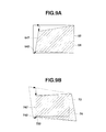
- the geometric correction adjustment unit 13a performs adjustment of image transformation that is performed by the geometric correction unit 13b on an image represented by using the micromirror element 15. That is, when the user presses the up button, the geometric correction adjustment unit 13a shifts the lower left corner 642 of the effective element region 64 upward along the left side 647 of the effective element region 64 to transform the effective element region 64, as illustrated in FIG. 9A . In this case, as illustrated in FIG.
- the user operates the up/down button of the operation unit 28 such that the lower left corner 742 of the projection region 74 is matched with a lower left corner 722 of the projection target region 72. While checking the projection region 74, the user presses the OK button of the operation unit 28 when the lower left corner 742 of the projection region 74 is matched with the lower left corner 722 of the projection target region 72. When the OK button of the operation unit 28 is pressed, the vertical-direction adjustment processing of a lower left vertex is ended.
- step S7 the vertical-direction adjustment processing of the lower left vertex is similar to the vertical-direction adjustment processing of the upper left vertex (step S4) which has been described with reference to FIG. 4B .
- step S7 the geometric correction adjustment unit 13a starts horizontal-direction adjustment processing of a lower right vertex.
- a user presses, for example, the left button or right button of the cross key of the operation unit 28.
- the geometric correction adjustment unit 13a performs adjustment of image transformation that is performed by the geometric correction unit 13b on an image represented by using the micromirror element 15. That is, when the user presses the left button, the geometric correction adjustment unit 13a shifts a lower right corner 643 of the effective element region 64 to the left along the lower side 628 of the element region 62 as illustrated in FIG. 10A to transform the effective element region 64. In this case, as illustrated in FIG.
- the user operates the left/right button of the operation unit 28 such that a right side 749 of the projection region 74 comes into contact with a lower right corner 723 of the projection target region 72.
- the user presses the OK button of the operation unit 28 when the right side 749 of the projection region 74 comes into contact with the lower right corner 723 of the projection target region 72.
- the OK button of the operation unit 28 is pressed, the horizontal-direction adjustment processing of the lower right vertex is ended. Subsequently, the processing proceeds to step S8.
- step S8 the geometric correction adjustment unit 13a starts vertical-direction adjustment processing of the lower right vertex.
- the user presses, for example, the up button or down button of the cross key of the operation unit 28.
- the geometric correction adjustment unit 13a performs adjustment of image transformation that is performed by the geometric correction unit 13b on an image represented by using the micromirror element 15. That is, when the user presses the up button, the geometric correction adjustment unit 13a shifts a lower right corner 643 of the effective element region 64 upward along a right side 649 of the effective element region 64 to transform the effective element region 64, as illustrated in FIG. 11A . In this case, as illustrated in FIG.
- the user operates the up/down button of the operation unit 28 such that the lower right corner 743 of the projection region 74 is matched with the lower right corner 723 of the projection target region 72.
- the user presses the OK button of the operation unit 28 when the lower right corner 743 of the projection region 74 is matched with the lower right corner 723 of the projection target region 72.
- the OK button of the operation unit 28 is pressed, the vertical-direction adjustment processing of a lower right vertex is ended.
- step S9 the vertical-direction adjustment processing of a lower right vertex is similar to the vertical-direction adjustment processing of an upper left vertex (step S4) which has been described with reference to FIG. 4B .
- step S9 the geometric correction adjustment unit 13a starts horizontal-direction adjustment processing of an upper right vertex.
- a user presses, for example, the left button or right button of the cross key of the operation unit 28.
- the geometric correction adjustment unit 13a performs adjustment of image transformation that is performed by the geometric correction unit 13b on an image represented by using the micromirror element 15. That is, as illustrated in FIG. 12A , when the user presses the left button, the geometric correction adjustment unit 13a shifts an upper right corner 644 of the effective element region 64 to the left along the upper side 626 of the element region 62 to transform the effective element region 64. In this case, as illustrated in FIG.
- an upper right corner 744 of the projection region 74 is shifted to the left along an upper side 756 of the projection region 74 before transformation, and therefore, the shape of the projection region 74 is changed.
- the effective element region 64 is adjusted such that the upper right corner 744 of the projection region 74 is shifted to the right along the upper side 756 of the projection region 74 before transformation.
- the user operates the left/right button of the operation unit 28 such that the right side 749 of the projection region 74 overlaps a right side 729 of the projection target region 72. While checking the projection region 74, the user presses the OK button of the operation unit 28 when the right side 749 of the projection region 74 comes into contact with the right side 729 of the projection target region 72. When the OK button of the operation unit 28 is pressed, the horizontal-direction adjustment processing of the upper-right vertex is ended. Subsequently, the processing proceeds to step S10.
- step S10 the geometric correction adjustment unit 13a starts vertical-direction adjustment processing of the upper right vertex.
- the user presses, for example, the up button or down button of the cross key of the operation unit 28.
- the geometric correction adjustment unit 13a performs adjustment of image transformation that is performed by the geometric correction unit 13b on an image represented by using the micromirror element 15. That is, as illustrated in FIG. 13A , when the user presses the down button, the geometric correction adjustment unit 13a shifts an upper right corner 644 of the effective element region 64 downward along a right side 649 of the effective element region 64 to transform the effective element region 64. In this case, as illustrated in FIG.
- the upper right corner 744 of the projection region 74 is shifted downward along the right side 749 of the projection region 74, and therefore, the shape of the projection region 74 is changed.
- the effective element region 64 is adjusted such that the upper right corner 744 of the projection region 74 is shifted downward along the right side 749 of the projection region 74.
- the user operates the up/down button of the operation unit 28 such that the upper right corner 744 of the projection region 74 is matched with the upper right corner 724 of the projection target region 72.
- the user presses the OK button of the operation unit 28 when the upper right corner 744 of the projection region 74 is matched with the upper right corner 724 of the projection target region 72.
- the OK button of the operation unit 28 is pressed, the vertical-direction adjustment processing of an upper light vertex is ended.
- the processing is ended.
- the vertical-direction adjustment processing of the upper right vertex is similar to the vertical-direction adjustment processing of the upper left vertex (step S4) which has been described with reference to FIG. 4B .
- an image transformation formula required to match the projection region 74 with the rectangular projection target region 72 is obtained.
- the projector 1 according to the present embodiment stores the image transformation formula obtained as described above.
- the image transformation unit 13 performs image transformation using the image transformation formula upon image projection. Consequently, an image can be projected on a projection target object without distortion.
- a projector having a function of performing setting of geometric correction for projecting an image on a projection target object without distortion while shifting a vertex of a projection region by using, for example, a cross key.
- setting of geometric correction in general, a vertex of an effective element region is shifted in parallel to an side of an element region of the micromirror element 15 in response to an input through the cross key. That is, after the horizontal-direction adjustment processing of an upper left vertex as described with reference to FIGS. 6A and 6B , the following operation is performed on processing corresponding to the vertical-direction adjustment processing of the upper left vertex as described with reference to FIGS. 7A and 7B .
- the user presses, for example, the up button or down button of the cross key of the operation unit 28. That is, when the user presses the down button, as illustrated in FIG. 14A , the effective element region is transformed such that the upper left corner 641 of the effective element region 64 is shifted downward in parallel with the left side 627 of the element region 62.
- the upper left corner 741 of the projection region 74 is shifted downward in parallel with the left side 757 of the projection region 74 before transformation, and therefore, the shape of the projection region 74 is transformed.
- the upper left corner 741 of the projection region 74 is not matched with the upper left corner 721 of the projection target region 72.
- the user repeatedly performs adjustment through the left/right button and adjustment through the up/down button in order to match the upper left corner 741 of the projection region 74 with the upper left corner 721 of the projection target region 72. It is inconvenient to repeatedly perform adjustment through the left/right button and adjustment through the up/down button.
- step S4 adjustment is easily performed in, for example, step S4, as compared with the above-described general adjustment method. That is, when the user presses the down button, as illustrated in FIG. 7A , the upper left corner 641 of the effective element region 64 is shifted downward along the left side 647 of the effective element region 64. Thus, as illustrated in FIG. 7B , the upper left corner 741 of the projection region 74 is directly shifted in a straight line toward the upper left corner 721 of the projection target region 72 along the left side 747 of the projection region 74. Consequently, the user can match the upper left corner 741 of the projection region 74 with the upper left corner 721 of the projection target region 72 by a single operation. In this way, the user easily performs adjustment according to the present embodiment.
- the effective element region 64 in the element region 62 is transformed so as to shift a vertex of the effective element region 64 along an side, an end of which is the vertex, according to the adjustment instruction input to the operation unit 28, thereby making it possible for the user to easily perform adjustment for geometric correction.
- the above described embodiment represents examples in which, upon horizontal-direction adjustment processing of respective vertexes, the respective vertexes of the effective element region 64 are shifted along the upper side 626 or the lower side 628 of the element region 62.
- a configuration may be made such that the respective vertexes of the effective element region 64 are shifted along the upper side 646 or the lower side 648 of the effective element region 64.
- the horizontal-direction adjustment processing of the lower right vertex in step S7 as described with reference to FIGS. 10A and 10B is performed as follows. That is, when the user presses the left button, as illustrated in FIG. 15A , the geometric correction adjustment unit 13a shifts the lower right corner 643 of the effective element region 64 to the left along the lower side 648 of the effective element region 64 to transform the effective element region 64. In this case, as illustrated in FIG. 15B , in the projected image, the lower right corner 743 of the projection region 74 is shifted to the left along the lower side 748 of the projection region 74, and therefore, the shape of the projection region 74 is changed.
- the respective vertexes of the projection region 74 are shifted along the respective sides of the projection region 74, and therefore, the user easily recognizes shift directions of the respective vertexes. Consequently, the user easily performs adjustment associated with geometric correction. Also, it is possible to reduce an adjustment amount in the subsequent horizontal-direction adjustment processing of the lower right vertex.
- the vertical-direction adjustment processing is performed after the horizontal-direction adjustment processing, with respect to the respective vertexes.
- a configuration may be made such that the horizontal-direction adjustment processing is performed after the vertical-direction adjustment processing.
- a configuration is made such that a vertex of the effective element region 64 is shifted along an side of the effective element region upon the latter adjustment processing, that is, the horizontal-direction adjustment processing, and therefore, a vertex of the projection region is directly shifted in a straight line toward a vertex of the projection target region, thereby achieving the effects of the present embodiment.
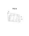
- an adjustment target mark 76 indicating a vertex to be shifted in the projection region 74 by an instruction of a user may be included in an adjustment chart that is projected on the projection target object upon adjustment of geometric correction.
- the user can easily recognize a vertex that is being adjusted.
- the adjustment target mark 76 is an arrow and a shifting vertex is indicated by the arrow in FIG. 16
- the shifting vertex may be indicated by any symbol.
- the chart for adjustment includes a straight line indicating the outline of the projection region 74, and therefore, the user easily recognizes the outline of the projection region 74 and performs adjustment of geometric correction without difficulty.
- geometric correction in a projector using a micromirror element is illustrated as an example in the present embodiment, geometric correction according to the above embodiments and modification examples may be used for a projector using another element such as a liquid crystal element.
- the geometric correction adjustment unit 13a is provided separately from the geometric correction unit 13b in the present embodiment, a configuration may of course be made such that the functions of the both are performed by a single control unit.
- the image transformation unit 13 is provided separately from the CPU 25 that controls operations of the image transformation unit 13, the projection processing unit 14, and the sound processing unit 30 in the present embodiment, a configuration may of course be made such that the function of the image transformation unit 13 is performed by the CPU 25 alone (single control unit).
Landscapes
- Physics & Mathematics (AREA)
- Geometry (AREA)
- Engineering & Computer Science (AREA)
- Multimedia (AREA)
- Signal Processing (AREA)
- Projection Apparatus (AREA)
- Transforming Electric Information Into Light Information (AREA)
Applications Claiming Priority (1)
| Application Number | Priority Date | Filing Date | Title |
|---|---|---|---|
| JP2013262307A JP6322993B2 (ja) | 2013-12-19 | 2013-12-19 | 幾何学補正調整方法 |
Publications (3)
| Publication Number | Publication Date |
|---|---|
| EP2887658A2 true EP2887658A2 (de) | 2015-06-24 |
| EP2887658A3 EP2887658A3 (de) | 2015-07-29 |
| EP2887658B1 EP2887658B1 (de) | 2020-04-08 |
Family
ID=52133881
Family Applications (1)
| Application Number | Title | Priority Date | Filing Date |
|---|---|---|---|
| EP14198184.5A Active EP2887658B1 (de) | 2013-12-19 | 2014-12-16 | Geometrisches Korrekturanpassungsverfahren |
Country Status (4)
| Country | Link |
|---|---|
| US (1) | US9565408B2 (de) |
| EP (1) | EP2887658B1 (de) |
| JP (1) | JP6322993B2 (de) |
| CN (1) | CN104730820B (de) |
Cited By (1)
| Publication number | Priority date | Publication date | Assignee | Title |
|---|---|---|---|---|
| CN111654680A (zh) * | 2019-03-04 | 2020-09-11 | 安世亚太科技股份有限公司 | 一种数字光处理光机的投影拼接方法及装置 |
Families Citing this family (9)
| Publication number | Priority date | Publication date | Assignee | Title |
|---|---|---|---|---|
| JP6274839B2 (ja) * | 2013-12-04 | 2018-02-07 | キヤノン株式会社 | 画像処理装置、画像処理方法 |
| US20160191878A1 (en) * | 2014-12-25 | 2016-06-30 | Panasonic Intellectual Property Management Co., Ltd. | Image projection device |
| CN105072430B (zh) * | 2015-08-19 | 2017-10-03 | 海信集团有限公司 | 一种调整投影图像的方法和设备 |
| CN106162124B (zh) * | 2016-08-02 | 2018-06-08 | 上海唱风信息科技有限公司 | 投影机输出图像的校准方法 |
| CN107845077B (zh) * | 2017-11-01 | 2021-11-16 | 中国科学院长春光学精密机械与物理研究所 | 一种校正dmd微镜元成像非对称形变的方法和存储介质 |
| CN108845476A (zh) * | 2018-09-04 | 2018-11-20 | 江苏清投视讯科技有限公司 | 基于内置图像几何调整单元的dlp背投系统 |
| JP7467947B2 (ja) * | 2020-01-31 | 2024-04-16 | セイコーエプソン株式会社 | 画像投射システムの制御方法、及び画像投射システム |
| CN114286065A (zh) * | 2020-09-28 | 2022-04-05 | 成都极米科技股份有限公司 | 投影画面调节方法、装置、投影仪和存储介质 |
| CN115529443B (zh) * | 2021-06-25 | 2026-04-07 | 成都极米科技股份有限公司 | 投影校正方法、装置、投影设备及存储介质 |
Citations (1)
| Publication number | Priority date | Publication date | Assignee | Title |
|---|---|---|---|---|
| JP2006227441A (ja) | 2005-02-18 | 2006-08-31 | Sharp Corp | プロジェクタ及び画像表示方法 |
Family Cites Families (18)
| Publication number | Priority date | Publication date | Assignee | Title |
|---|---|---|---|---|
| JP2002044571A (ja) * | 2000-07-27 | 2002-02-08 | Nec Viewtechnology Ltd | 投射型の格子状表示装置及び投射映像の歪み補正方法 |
| JP3742027B2 (ja) * | 2002-04-08 | 2006-02-01 | Necビューテクノロジー株式会社 | 投射映像の歪補正方法、歪補正プログラム及び投射型映像表示装置 |
| US6963348B2 (en) * | 2002-05-31 | 2005-11-08 | Nvidia Corporation | Method and apparatus for display image adjustment |
| EP1512283B1 (de) * | 2002-06-12 | 2008-05-21 | Silicon Optix Inc. | Bildprojektionssystem und -verfahren für kurze Reichweiten |
| JP2004274283A (ja) * | 2003-03-07 | 2004-09-30 | Casio Comput Co Ltd | 投影システム、及び投影装置、画像供給装置、プログラム |
| JP4042695B2 (ja) * | 2004-01-08 | 2008-02-06 | セイコーエプソン株式会社 | プロジェクタおよびズーム調整方法 |
| US7399086B2 (en) * | 2004-09-09 | 2008-07-15 | Jan Huewel | Image processing method and image processing device |
| JP5251010B2 (ja) * | 2007-06-19 | 2013-07-31 | セイコーエプソン株式会社 | 画像処理装置、プロジェクタ |
| JP5386828B2 (ja) * | 2008-01-29 | 2014-01-15 | セイコーエプソン株式会社 | 画像投影システムおよびプログラム |
| JP5405047B2 (ja) * | 2008-05-09 | 2014-02-05 | 三洋電機株式会社 | 投写型映像表示装置 |
| JP5509663B2 (ja) * | 2009-04-15 | 2014-06-04 | セイコーエプソン株式会社 | プロジェクター及びその制御方法 |
| CA2766989A1 (en) * | 2009-07-02 | 2011-01-06 | Thomson Licensing | Method and system for differential distortion correction for three-dimensional (3d) projection |
| KR101699956B1 (ko) * | 2009-08-12 | 2017-01-25 | 톰슨 라이센싱 | 3차원(3d) 투사용의 누화 및 왜곡 보정을 위한 방법 및 시스템 |
| JP5884380B2 (ja) * | 2011-09-30 | 2016-03-15 | セイコーエプソン株式会社 | プロジェクター、およびプロジェクターの制御方法 |
| CN103034030B (zh) * | 2011-09-30 | 2016-05-04 | 精工爱普生株式会社 | 投影仪以及投影仪的控制方法 |
| JP5887804B2 (ja) * | 2011-09-30 | 2016-03-16 | セイコーエプソン株式会社 | プロジェクター、及び、プロジェクターの制御方法 |
| JP6164820B2 (ja) * | 2012-10-11 | 2017-07-19 | キヤノン株式会社 | プロジェクタ、その制御方法、及び画像投影システム |
| US9514716B2 (en) * | 2012-10-19 | 2016-12-06 | Casio Computer Co., Ltd. | Projection apparatus, projection control apparatus, projection system, and projection state adjustment method |
-
2013
- 2013-12-19 JP JP2013262307A patent/JP6322993B2/ja active Active
-
2014
- 2014-12-16 EP EP14198184.5A patent/EP2887658B1/de active Active
- 2014-12-18 US US14/575,690 patent/US9565408B2/en not_active Expired - Fee Related
- 2014-12-19 CN CN201410805572.7A patent/CN104730820B/zh active Active
Patent Citations (1)
| Publication number | Priority date | Publication date | Assignee | Title |
|---|---|---|---|---|
| JP2006227441A (ja) | 2005-02-18 | 2006-08-31 | Sharp Corp | プロジェクタ及び画像表示方法 |
Cited By (1)
| Publication number | Priority date | Publication date | Assignee | Title |
|---|---|---|---|---|
| CN111654680A (zh) * | 2019-03-04 | 2020-09-11 | 安世亚太科技股份有限公司 | 一种数字光处理光机的投影拼接方法及装置 |
Also Published As
| Publication number | Publication date |
|---|---|
| EP2887658B1 (de) | 2020-04-08 |
| US9565408B2 (en) | 2017-02-07 |
| EP2887658A3 (de) | 2015-07-29 |
| JP6322993B2 (ja) | 2018-05-16 |
| US20150181183A1 (en) | 2015-06-25 |
| CN104730820B (zh) | 2017-01-11 |
| CN104730820A (zh) | 2015-06-24 |
| JP2015119381A (ja) | 2015-06-25 |
Similar Documents
| Publication | Publication Date | Title |
|---|---|---|
| US9565408B2 (en) | Projection apparatus, geometric correction adjustment method, and storage medium storing codes for geometric correction adjustment | |
| US10341626B2 (en) | Image projection system, projector, and control method for image projection system | |
| JP3867205B2 (ja) | 指示位置検出装置、及び指示位置検出システム、並びに指示位置検出方法 | |
| JP6205777B2 (ja) | 投影装置、投影方法、及び投影のためのプログラム | |
| US10520797B2 (en) | Projection system, control device, and control method of projection system | |
| US10431131B2 (en) | Projector and control method for projector | |
| US10015457B2 (en) | Projector and control method with a starting reference position in a lower part of a target image | |
| CN104869373A (zh) | 图像显示装置以及图像显示装置的控制方法 | |
| JP6707871B2 (ja) | 画質補正方法、及び、画像投射システム | |
| US9578294B2 (en) | Projector and method for adjusting projector | |
| US8197069B2 (en) | Projection apparatus, projection method, and medium | |
| US11323673B2 (en) | Method for operating control apparatus, and projector | |
| JP5672126B2 (ja) | インタラクティブシステム、インタラクティブシステムの制御方法、およびプロジェクター | |
| JP6766716B2 (ja) | 情報処理装置、画像表示プログラム、画像表示方法および表示システム | |
| JP7071694B2 (ja) | 投影制御装置、投影システム、投影制御装置の投影制御方法、及びプログラム | |
| JP6665543B2 (ja) | プロジェクター、及び、撮像画像の補正方法 | |
| JP5504697B2 (ja) | 投影システム、投影装置、音声制御方法及びプログラム | |
| JP2012070031A (ja) | 画像表示システム、撮像装置、画像表示システムの制御方法、および撮像装置の制御方法 | |
| JP2017228884A (ja) | 画像処理装置、表示装置、及び、画像処理装置の制御方法 | |
| JP2015146611A (ja) | インタラクティブシステム、およびインタラクティブシステムの制御方法 | |
| JP2021089304A (ja) | 制御装置の動作方法および制御装置 | |
| JP2011158844A (ja) | 投影装置、投影方法及びプログラム | |
| JP7309352B2 (ja) | 電子機器およびその制御方法 | |
| JP5967183B2 (ja) | インタラクティブシステム、プロジェクター、およびプロジェクターの制御方法 | |
| JP2016161798A (ja) | プロジェクター、及び、プロジェクターの制御方法 |
Legal Events
| Date | Code | Title | Description |
|---|---|---|---|
| PUAI | Public reference made under article 153(3) epc to a published international application that has entered the european phase |
Free format text: ORIGINAL CODE: 0009012 |
|
| 17P | Request for examination filed |
Effective date: 20141216 |
|
| AK | Designated contracting states |
Kind code of ref document: A2 Designated state(s): AL AT BE BG CH CY CZ DE DK EE ES FI FR GB GR HR HU IE IS IT LI LT LU LV MC MK MT NL NO PL PT RO RS SE SI SK SM TR |
|
| AX | Request for extension of the european patent |
Extension state: BA ME |
|
| PUAL | Search report despatched |
Free format text: ORIGINAL CODE: 0009013 |
|
| AK | Designated contracting states |
Kind code of ref document: A3 Designated state(s): AL AT BE BG CH CY CZ DE DK EE ES FI FR GB GR HR HU IE IS IT LI LT LU LV MC MK MT NL NO PL PT RO RS SE SI SK SM TR |
|
| AX | Request for extension of the european patent |
Extension state: BA ME |
|
| RIC1 | Information provided on ipc code assigned before grant |
Ipc: H04N 9/31 20060101AFI20150624BHEP |
|
| STAA | Information on the status of an ep patent application or granted ep patent |
Free format text: STATUS: EXAMINATION IS IN PROGRESS |
|
| 17Q | First examination report despatched |
Effective date: 20170926 |
|
| GRAP | Despatch of communication of intention to grant a patent |
Free format text: ORIGINAL CODE: EPIDOSNIGR1 |
|
| STAA | Information on the status of an ep patent application or granted ep patent |
Free format text: STATUS: GRANT OF PATENT IS INTENDED |
|
| INTG | Intention to grant announced |
Effective date: 20191023 |
|
| GRAS | Grant fee paid |
Free format text: ORIGINAL CODE: EPIDOSNIGR3 |
|
| GRAA | (expected) grant |
Free format text: ORIGINAL CODE: 0009210 |
|
| STAA | Information on the status of an ep patent application or granted ep patent |
Free format text: STATUS: THE PATENT HAS BEEN GRANTED |
|
| AK | Designated contracting states |
Kind code of ref document: B1 Designated state(s): AL AT BE BG CH CY CZ DE DK EE ES FI FR GB GR HR HU IE IS IT LI LT LU LV MC MK MT NL NO PL PT RO RS SE SI SK SM TR |
|
| REG | Reference to a national code |
Ref country code: AT Ref legal event code: REF Ref document number: 1255951 Country of ref document: AT Kind code of ref document: T Effective date: 20200415 Ref country code: CH Ref legal event code: EP |
|
| REG | Reference to a national code |
Ref country code: IE Ref legal event code: FG4D |
|
| REG | Reference to a national code |
Ref country code: DE Ref legal event code: R096 Ref document number: 602014063437 Country of ref document: DE |
|
| REG | Reference to a national code |
Ref country code: NL Ref legal event code: MP Effective date: 20200408 |
|
| REG | Reference to a national code |
Ref country code: LT Ref legal event code: MG4D |
|
| PG25 | Lapsed in a contracting state [announced via postgrant information from national office to epo] |
Ref country code: PT Free format text: LAPSE BECAUSE OF FAILURE TO SUBMIT A TRANSLATION OF THE DESCRIPTION OR TO PAY THE FEE WITHIN THE PRESCRIBED TIME-LIMIT Effective date: 20200817 Ref country code: FI Free format text: LAPSE BECAUSE OF FAILURE TO SUBMIT A TRANSLATION OF THE DESCRIPTION OR TO PAY THE FEE WITHIN THE PRESCRIBED TIME-LIMIT Effective date: 20200408 Ref country code: GR Free format text: LAPSE BECAUSE OF FAILURE TO SUBMIT A TRANSLATION OF THE DESCRIPTION OR TO PAY THE FEE WITHIN THE PRESCRIBED TIME-LIMIT Effective date: 20200709 Ref country code: NL Free format text: LAPSE BECAUSE OF FAILURE TO SUBMIT A TRANSLATION OF THE DESCRIPTION OR TO PAY THE FEE WITHIN THE PRESCRIBED TIME-LIMIT Effective date: 20200408 Ref country code: LT Free format text: LAPSE BECAUSE OF FAILURE TO SUBMIT A TRANSLATION OF THE DESCRIPTION OR TO PAY THE FEE WITHIN THE PRESCRIBED TIME-LIMIT Effective date: 20200408 Ref country code: IS Free format text: LAPSE BECAUSE OF FAILURE TO SUBMIT A TRANSLATION OF THE DESCRIPTION OR TO PAY THE FEE WITHIN THE PRESCRIBED TIME-LIMIT Effective date: 20200808 Ref country code: NO Free format text: LAPSE BECAUSE OF FAILURE TO SUBMIT A TRANSLATION OF THE DESCRIPTION OR TO PAY THE FEE WITHIN THE PRESCRIBED TIME-LIMIT Effective date: 20200708 Ref country code: SE Free format text: LAPSE BECAUSE OF FAILURE TO SUBMIT A TRANSLATION OF THE DESCRIPTION OR TO PAY THE FEE WITHIN THE PRESCRIBED TIME-LIMIT Effective date: 20200408 |
|
| REG | Reference to a national code |
Ref country code: AT Ref legal event code: MK05 Ref document number: 1255951 Country of ref document: AT Kind code of ref document: T Effective date: 20200408 |
|
| PG25 | Lapsed in a contracting state [announced via postgrant information from national office to epo] |
Ref country code: LV Free format text: LAPSE BECAUSE OF FAILURE TO SUBMIT A TRANSLATION OF THE DESCRIPTION OR TO PAY THE FEE WITHIN THE PRESCRIBED TIME-LIMIT Effective date: 20200408 Ref country code: HR Free format text: LAPSE BECAUSE OF FAILURE TO SUBMIT A TRANSLATION OF THE DESCRIPTION OR TO PAY THE FEE WITHIN THE PRESCRIBED TIME-LIMIT Effective date: 20200408 Ref country code: RS Free format text: LAPSE BECAUSE OF FAILURE TO SUBMIT A TRANSLATION OF THE DESCRIPTION OR TO PAY THE FEE WITHIN THE PRESCRIBED TIME-LIMIT Effective date: 20200408 Ref country code: BG Free format text: LAPSE BECAUSE OF FAILURE TO SUBMIT A TRANSLATION OF THE DESCRIPTION OR TO PAY THE FEE WITHIN THE PRESCRIBED TIME-LIMIT Effective date: 20200708 |
|
| PG25 | Lapsed in a contracting state [announced via postgrant information from national office to epo] |
Ref country code: AL Free format text: LAPSE BECAUSE OF FAILURE TO SUBMIT A TRANSLATION OF THE DESCRIPTION OR TO PAY THE FEE WITHIN THE PRESCRIBED TIME-LIMIT Effective date: 20200408 |
|
| REG | Reference to a national code |
Ref country code: DE Ref legal event code: R097 Ref document number: 602014063437 Country of ref document: DE |
|
| PG25 | Lapsed in a contracting state [announced via postgrant information from national office to epo] |
Ref country code: DK Free format text: LAPSE BECAUSE OF FAILURE TO SUBMIT A TRANSLATION OF THE DESCRIPTION OR TO PAY THE FEE WITHIN THE PRESCRIBED TIME-LIMIT Effective date: 20200408 Ref country code: AT Free format text: LAPSE BECAUSE OF FAILURE TO SUBMIT A TRANSLATION OF THE DESCRIPTION OR TO PAY THE FEE WITHIN THE PRESCRIBED TIME-LIMIT Effective date: 20200408 Ref country code: ES Free format text: LAPSE BECAUSE OF FAILURE TO SUBMIT A TRANSLATION OF THE DESCRIPTION OR TO PAY THE FEE WITHIN THE PRESCRIBED TIME-LIMIT Effective date: 20200408 Ref country code: CZ Free format text: LAPSE BECAUSE OF FAILURE TO SUBMIT A TRANSLATION OF THE DESCRIPTION OR TO PAY THE FEE WITHIN THE PRESCRIBED TIME-LIMIT Effective date: 20200408 Ref country code: RO Free format text: LAPSE BECAUSE OF FAILURE TO SUBMIT A TRANSLATION OF THE DESCRIPTION OR TO PAY THE FEE WITHIN THE PRESCRIBED TIME-LIMIT Effective date: 20200408 Ref country code: IT Free format text: LAPSE BECAUSE OF FAILURE TO SUBMIT A TRANSLATION OF THE DESCRIPTION OR TO PAY THE FEE WITHIN THE PRESCRIBED TIME-LIMIT Effective date: 20200408 Ref country code: SM Free format text: LAPSE BECAUSE OF FAILURE TO SUBMIT A TRANSLATION OF THE DESCRIPTION OR TO PAY THE FEE WITHIN THE PRESCRIBED TIME-LIMIT Effective date: 20200408 Ref country code: EE Free format text: LAPSE BECAUSE OF FAILURE TO SUBMIT A TRANSLATION OF THE DESCRIPTION OR TO PAY THE FEE WITHIN THE PRESCRIBED TIME-LIMIT Effective date: 20200408 |
|
| PLBE | No opposition filed within time limit |
Free format text: ORIGINAL CODE: 0009261 |
|
| STAA | Information on the status of an ep patent application or granted ep patent |
Free format text: STATUS: NO OPPOSITION FILED WITHIN TIME LIMIT |
|
| PG25 | Lapsed in a contracting state [announced via postgrant information from national office to epo] |
Ref country code: PL Free format text: LAPSE BECAUSE OF FAILURE TO SUBMIT A TRANSLATION OF THE DESCRIPTION OR TO PAY THE FEE WITHIN THE PRESCRIBED TIME-LIMIT Effective date: 20200408 Ref country code: SK Free format text: LAPSE BECAUSE OF FAILURE TO SUBMIT A TRANSLATION OF THE DESCRIPTION OR TO PAY THE FEE WITHIN THE PRESCRIBED TIME-LIMIT Effective date: 20200408 |
|
| 26N | No opposition filed |
Effective date: 20210112 |
|
| PG25 | Lapsed in a contracting state [announced via postgrant information from national office to epo] |
Ref country code: SI Free format text: LAPSE BECAUSE OF FAILURE TO SUBMIT A TRANSLATION OF THE DESCRIPTION OR TO PAY THE FEE WITHIN THE PRESCRIBED TIME-LIMIT Effective date: 20200408 |
|
| REG | Reference to a national code |
Ref country code: CH Ref legal event code: PL |
|
| PG25 | Lapsed in a contracting state [announced via postgrant information from national office to epo] |
Ref country code: MC Free format text: LAPSE BECAUSE OF FAILURE TO SUBMIT A TRANSLATION OF THE DESCRIPTION OR TO PAY THE FEE WITHIN THE PRESCRIBED TIME-LIMIT Effective date: 20200408 |
|
| REG | Reference to a national code |
Ref country code: BE Ref legal event code: MM Effective date: 20201231 |
|
| PG25 | Lapsed in a contracting state [announced via postgrant information from national office to epo] |
Ref country code: IE Free format text: LAPSE BECAUSE OF NON-PAYMENT OF DUE FEES Effective date: 20201216 Ref country code: LU Free format text: LAPSE BECAUSE OF NON-PAYMENT OF DUE FEES Effective date: 20201216 |
|
| PG25 | Lapsed in a contracting state [announced via postgrant information from national office to epo] |
Ref country code: CH Free format text: LAPSE BECAUSE OF NON-PAYMENT OF DUE FEES Effective date: 20201231 Ref country code: LI Free format text: LAPSE BECAUSE OF NON-PAYMENT OF DUE FEES Effective date: 20201231 |
|
| PG25 | Lapsed in a contracting state [announced via postgrant information from national office to epo] |
Ref country code: TR Free format text: LAPSE BECAUSE OF FAILURE TO SUBMIT A TRANSLATION OF THE DESCRIPTION OR TO PAY THE FEE WITHIN THE PRESCRIBED TIME-LIMIT Effective date: 20200408 Ref country code: MT Free format text: LAPSE BECAUSE OF FAILURE TO SUBMIT A TRANSLATION OF THE DESCRIPTION OR TO PAY THE FEE WITHIN THE PRESCRIBED TIME-LIMIT Effective date: 20200408 Ref country code: CY Free format text: LAPSE BECAUSE OF FAILURE TO SUBMIT A TRANSLATION OF THE DESCRIPTION OR TO PAY THE FEE WITHIN THE PRESCRIBED TIME-LIMIT Effective date: 20200408 |
|
| PG25 | Lapsed in a contracting state [announced via postgrant information from national office to epo] |
Ref country code: MK Free format text: LAPSE BECAUSE OF FAILURE TO SUBMIT A TRANSLATION OF THE DESCRIPTION OR TO PAY THE FEE WITHIN THE PRESCRIBED TIME-LIMIT Effective date: 20200408 |
|
| PG25 | Lapsed in a contracting state [announced via postgrant information from national office to epo] |
Ref country code: BE Free format text: LAPSE BECAUSE OF NON-PAYMENT OF DUE FEES Effective date: 20201231 |
|
| PGFP | Annual fee paid to national office [announced via postgrant information from national office to epo] |
Ref country code: DE Payment date: 20251028 Year of fee payment: 12 |
|
| PGFP | Annual fee paid to national office [announced via postgrant information from national office to epo] |
Ref country code: GB Payment date: 20251030 Year of fee payment: 12 |
|
| PGFP | Annual fee paid to national office [announced via postgrant information from national office to epo] |
Ref country code: FR Payment date: 20251110 Year of fee payment: 12 |