EP2886984A2 - Procédé de séchage et/ou de cristallisation de produits en vrac et installation d'exécution d'un tel procédé - Google Patents
Procédé de séchage et/ou de cristallisation de produits en vrac et installation d'exécution d'un tel procédé Download PDFInfo
- Publication number
- EP2886984A2 EP2886984A2 EP14004216.9A EP14004216A EP2886984A2 EP 2886984 A2 EP2886984 A2 EP 2886984A2 EP 14004216 A EP14004216 A EP 14004216A EP 2886984 A2 EP2886984 A2 EP 2886984A2
- Authority
- EP
- European Patent Office
- Prior art keywords
- drying
- bulk material
- drying medium
- tube
- container
- Prior art date
- Legal status (The legal status is an assumption and is not a legal conclusion. Google has not performed a legal analysis and makes no representation as to the accuracy of the status listed.)
- Withdrawn
Links
Images


Classifications
-
- F—MECHANICAL ENGINEERING; LIGHTING; HEATING; WEAPONS; BLASTING
- F26—DRYING
- F26B—DRYING SOLID MATERIALS OR OBJECTS BY REMOVING LIQUID THEREFROM
- F26B17/00—Machines or apparatus for drying materials in loose, plastic, or fluidised form, e.g. granules, staple fibres, with progressive movement
- F26B17/12—Machines or apparatus for drying materials in loose, plastic, or fluidised form, e.g. granules, staple fibres, with progressive movement with movement performed solely by gravity, i.e. the material moving through a substantially vertical drying enclosure, e.g. shaft
- F26B17/128—Machines or apparatus for drying materials in loose, plastic, or fluidised form, e.g. granules, staple fibres, with progressive movement with movement performed solely by gravity, i.e. the material moving through a substantially vertical drying enclosure, e.g. shaft with provisions for working under reduced or increased pressure, with or without heating
-
- F—MECHANICAL ENGINEERING; LIGHTING; HEATING; WEAPONS; BLASTING
- F26—DRYING
- F26B—DRYING SOLID MATERIALS OR OBJECTS BY REMOVING LIQUID THEREFROM
- F26B5/00—Drying solid materials or objects by processes not involving the application of heat
- F26B5/04—Drying solid materials or objects by processes not involving the application of heat by evaporation or sublimation of moisture under reduced pressure, e.g. in a vacuum
- F26B5/041—Drying solid materials or objects by processes not involving the application of heat by evaporation or sublimation of moisture under reduced pressure, e.g. in a vacuum for drying flowable materials, e.g. suspensions, bulk goods, in a continuous operation, e.g. with locks or other air tight arrangements for charging/discharging
-
- F—MECHANICAL ENGINEERING; LIGHTING; HEATING; WEAPONS; BLASTING
- F26—DRYING
- F26B—DRYING SOLID MATERIALS OR OBJECTS BY REMOVING LIQUID THEREFROM
- F26B21/00—Arrangements or duct systems, e.g. in combination with pallet boxes, for supplying and controlling air or gases for drying solid materials or objects
- F26B21/06—Controlling, e.g. regulating, parameters of gas supply
- F26B21/10—Temperature; Pressure
-
- F—MECHANICAL ENGINEERING; LIGHTING; HEATING; WEAPONS; BLASTING
- F26—DRYING
- F26B—DRYING SOLID MATERIALS OR OBJECTS BY REMOVING LIQUID THEREFROM
- F26B25/00—Details of general application not covered by group F26B21/00 or F26B23/00
- F26B25/04—Agitating, stirring, or scraping devices
Definitions
- the invention relates to a method for drying and / or crystallizing bulk material, in particular plastic granules, according to the preamble of claim 1 and a system for carrying out such a method according to the preamble of claim 9.
- the drying container is preferably always completely filled with bulk material.
- the drying medium used for drying the bulk material is generally introduced from below into the drying container and passed in countercurrent through the bulk material. The bulk material and the moisture contained in the bulk material are heated by the drying medium, which expels the moisture from the bulk material.
- the drying medium which flows in countercurrent from bottom to top through the bulk material, dehumidifies the bulk material only slowly, because the introduced from below drying medium emits energy on the way through the drying tank and thereby also decreases the temperature of the drying medium on the way through the bulk material.
- the temperature With a small specific amount of drying medium based on the bulk material throughput, the temperature will increase more towards the top in the drying tank than at high specific air volume.
- the drying medium When passing through the bulk material also absorbs moisture from the bulk material, the drying medium on the way through the bulk material is wet, whereby the drying performance decreases in addition.
- drying containers which have two tubes, between which a bulk material space is formed and which are each formed as perforated tubes.
- the drying medium is introduced into the inner tube. It flows through the holes of the inner tube to the outside, flows through the bulk material and absorbs moisture from the bulk material and heats it.
- the drying medium then flows out through the holes of the outer tube into the container interior and flows to an outlet. Since the drying medium flows through the bulk material transversely to the axis of the drying container, resulting in only short drying times. Due to the cross-flow is achieved that in each level the same drying temperature and thus also the same minimum dew point of the drying medium is present.
- the invention has the object of providing the generic method and the generic system in such a way that the drying times for the bulk material can be considerably shortened with a simple structural design and process control.
- the drying space in which the bulk material is to be treated is subjected to negative pressure, at least for part of the drying time.
- the drying space in which the bulk material is to be treated is subjected to negative pressure, at least for part of the drying time.
- the bulk material is applied alternately with the drying medium and with negative pressure.
- the drying medium is passed through the bulk material in a first phase.
- a second phase the supply of the drying medium is interrupted and via a valve control the system is switched so that at least in the drying room creates a negative pressure, which is maintained for a certain time.
- the duration of time can be fixed, but can also be varied depending on a measured degree of humidity.
- the system is switched over again by means of the valve control, so that the drying medium flows through the bulk material.
- the bulk material can also be applied simultaneously with the drying medium and with negative pressure. This is advantageously achieved by using an additional vacuum generator, preferably a blower, with which a filling device of the drying container is switched into the system circuit.
- the negative pressure amplifies the vapor pressure difference between the drying medium and the bulk material to be dried, which advantageously contributes to a short drying time.
- the drying medium is circulated through the drying tank. A portion of the drying medium is fed to a dehumidifier after flowing through the bulk material. Since only a portion of the drying medium is always supplied to the dehumidifying device for dehumidifying, the energy consumption can be kept low.
- the dehumidifying device is advantageously arranged only in a secondary flow, it is not necessary to dehumidify the entire amount of drying medium.
- a heat exchanger is used between the discharge and the supply line of the partial flow of the drying medium in order to optimally use the heat energy contained in the partial flow of the drying medium.
- the part of the drying medium which has been dehumidified in the dehumidifying device is returned to the drying medium flowing to the drying container.
- the temperature of the drying medium is adjusted by at least one heating device and at least one temperature sensor via a control device to a temperature adapted to the bulk material.
- At least one vacuum generator is provided, which sets at least the drying space of the drying container under negative pressure.
- the vacuum generator is a blower, on whose suction side a filling device for the bulk material is connected.
- the system has a valve control, with which the vacuum generator is switchable so that it promotes air out of the air circuit of the system and the drying container in the ambient space. This creates a negative pressure in the entire flow space and thus also in the drying room.
- a material lock is connected, which has two valves, between which an intermediate space for the bulk material is arranged.
- the outlet of the drying container is connected via at least one line to a melting region of a processing machine for the bulk material.
- the negative pressure prevailing in the melting area ensures that outgassing moisture or other volatile substances can be removed from the bulk material at the beginning of the melting phase.
- the drying container is designed so that the drying medium enters the drying chamber so that the bulk material is always only partially applied in the drying room with the drying medium.
- the drying medium is introduced so that it acts on only part of the bulk material in the drying room.
- the drying medium is passed through the bulk material transversely to the direction of movement of the bulk material flow in the drying container, resulting in optimally short drying times.
- the drying medium can be supplied not only continuously but also in phases for drying and / or for crystallization of the bulk material.
- the drying medium can be introduced into the bulk material at a particularly high speed.
- This phased process management also allows a higher diffusion rate of moisture from the bulk material.
- a slipping of the bulk material is achieved by the resting phases between the introduction of the drying medium, which would otherwise remain in the drying tank, especially if a very high speed of the drying medium is used.
- the entire drying unit can be built small, which brings a significant advantage in handling the bulk material with it.
- Baffles are advantageously provided on one of the two tubes of the drying container, with which a partial flow through the bulk material is made by the drying medium.
- These internals may be formed in an advantageous embodiment by an inner tube or an outer tube which is rotatably mounted in the inner tube or on the outer tube of the drying container.
- the inner / outer tube has at least one, preferably a plurality of passage openings for the passage of the drying medium.
- the drying medium can flow into the bulk material.
- the inner or the outer tube is advantageously a perforated tube whose holes are covered by the inner tube or the outer tube, except for the region of the passage opening (s). Therefore, the drying medium can flow only through the passage opening of the rotatable inner or outer tube and lying in this area holes of the inner or outer tube in the bulk material. The remaining holes of the inner and outer tubes are covered by the inner and the outer tube. In this way it is very easy to achieve that the bulk material is only partially loaded with the drying medium. Since the inner and the outer tube is rotated about its axis, the drying medium flow emerging from the passage opening reaches all areas of the bulk material with a 360 ° rotation.
- the passage opening of the inner or outer tube may be, for example, an over the length of the tube extending, for example, slot-shaped opening. If the inner or outer tube is rotated about its axis, the drying medium is successively acted upon over its entire height partially by the drying medium.
- a drive For rotating the inner or outer tube, a drive is provided which may be located outside, but also inside the drying container.
- the passage opening of the inner or outer tube is advantageously greater by a multiple than the holes of the inner or outer tube. As a result, a sufficiently wide stream of drying medium can be conducted into the bulk material to be dried.
- At least one aperture is used as internals, which is axially displaceable in the inner tube or on the outer tube.
- the inner and the outer tube is in this case formed as a perforated tube.
- the orifice covers the holes of the pipe which it detects, so that no drying medium can pass through these covered holes of the pipe.
- the diaphragm is displaced in the axial direction of the inner or outer tube, so that successively different areas of the inner or outer tube covered or different areas are released for the passage of the drying medium. In this way, the entire bulk material in the bulk material annulus is gradually detected by the drying medium.
- the aperture is advantageously mounted on a piston rod which projects into the inner tube or into the drying container.
- the piston rod in turn sits on a piston, which is advantageously part of a pneumatic drive.
- the drive can be arranged inside or outside the drying container.
- Any suitable drive can be used as drive for the panel.
- two or more spaced apart diaphragms are present, which are advantageous together axially displaceable within the inner tube or on the outer tube.
- the drying medium can then enter the bulk material in the region between the successive diaphragms through the holes of the inner or outer tube.
- the internals are formed by at least one stirring blade, which protrudes from the inner or outer tube into the bulk material annulus.
- the inner and the outer tube is in this case rotatable about its axis. Turning the tube exposes the bulk material itself to movement. As a result, the drying medium passes into a correspondingly loosened region of the bulk material, whereby the formation of agglomerates is prevented during the crystallization of the bulk material.
- the bulk material itself stands from the inner wall of the outer tube or the outer wall of the inner tube at least one wing in the bulk material annulus.
- this wing is stationary and prevents the rotation of the tube with the impeller causing the bulk material to rotate.
- the stationary wing of a tube overlaps, seen in the axial direction of the two tubes, the agitator wing of the other tube. This ensures optimum effect of the two wings.
- the stirring blade is a hollow body into which the drying medium flows and which has at least one outflow opening for the drying medium.
- the tube must not be perforated, since the drying medium passes through the hollow body and its outflow opening in the bulk material.
- the impeller thus not only serves to set the bulk material in its effective range in motion, but to introduce targeted in this area the drying medium in the bulk material.
- the diameter of the perforated inner or outer tube can be designed differently. This has the consequence that the radial width of the bulk material annulus can be varied. As a result, the thickness of the bulk material is changed and greatly increases the relative movement of the individual bulk granules at low bulk material thickness. This leads advantageously to a reduced agglomeration during crystallization. In addition, this significantly reduces the drying time.
- the inner or outer tube is a perforated tube which is rotatable about its axis by means of a drive.
- this design of the drying container no stirring blades are necessary to move the bulk material in motion.
- the system serves to significantly reduce the throughput time for drying and / or crystallization of bulk material in a drying container by rapid heating and special process control.
- the system according to Fig. 1 has at least one drying container 1, which has a cylindrical shell 101, which merges into a conical jacket 102 at the lower end of the container 1. In the conical jacket 102 is located at the bottom of an outlet 8, through which the dried in the container 1 bulk material 3 is removed.
- the outer tube 2 extends from a cylindrical shell 101 at the upper end final ceiling 103 to the conical jacket 102.
- the inner tube 4 is spaced from the ceiling 103 as well from the conical jacket 102 of the heating tank. 1
- the bulk material 3 to be dried is introduced via a filling device 7 from the ceiling 103 into an annular space 104 which extends between the two tubes 2, 4. So that the bulk material 3 does not get into the inner tube 4, it is closed at the top. Even down the inner tube 4 is sealed so that the bulk material 3 can not get over the lower end in the inner tube 4.
- the filling device 7 is seated on the ceiling 103 and is formed in a known manner. It has at least one delivery container 105, which is mounted on the container to be filled 1.
- the filling device 7 is further provided with a vacuum station 106, which is connected via at least one line 107 to the delivery container 105.
- the bulk material is located in at least one (not shown) collecting container, which may be formed as a silo, a box or any container that can be filled with bulk material.
- the bulk material is introduced via the filling device 7 from above into the annular space 104 between the two tubes 2, 4 until the container 1 is filled to the maximum.
- the outlet 8 is closed in a known manner, for example by means of a slide.
- the bulk material 3 can be heated rapidly in the container 1, wherein moisture contained in the bulk material is withdrawn. It is also possible with the container 1 bulk materials such. B. PET (polyethylene terephthalate), from the amorphous to the crystalline state.
- PET polyethylene terephthalate
- the treated bulk material 3 can be removed continuously or batchwise from the container 1. According to the amount of bulk material removed from the container 1, new bulk material is advantageously always refilled with the filling device 7 in such a way that the annular space 104 is always completely filled.
- the throughput of bulk material 3 is adjusted so that the bulk material 3 is a defined time in the annular space 104.
- This residence time in annulus 104 is preferably between about 0.2 and about 8 hours.
- the residence time is matched to the type of bulk material and / or its moisture content.
- the residence time is chosen so that the bulk material has an optimal degree of drying, without the bulk material is damaged due to too long and / or too high drying temperature, for example, melts. If the bulk material has a high moisture content, the residence time in the annular space 104 is longer than with a less moist bulk material.
- the two tubes 2, 4 are formed as perforated tubes, so that the dry air, which is required for drying the bulk material 3, pass through the openings of the tubes to the bulk material or can flow out of the bulk material.
- the openings of the tubes 2, 4 are smaller than the grain size of the bulk material, so that the bulk material from the annular space 104 can not pass through the outer tube to the outside or through the openings of the inner tube 4 in the inner tube.
- the dry air required for treating the bulk material is fed via a line 12 to the inner tube 4.
- the dry air is brought by means of at least one heater 11 to the required drying temperature, if necessary.
- Dry air is preferably used as the drying medium, but may also be any suitable drying gas.
- a temperature sensor 50 In line 12 sits a temperature sensor 50, with which the temperature of the drying medium can be detected before entering the container 1.
- the heater 11 is preceded by a fan 10, which supplies the dry medium to the container 1.
- the dry medium passes via the line 12 into the inner tube 4.
- the dry medium flows over the length and over the circumference of the inner tube 4 through the openings radially outward, which is indicated by the indicated flow arrows.
- the dry medium flows through the bulk material located in the annular space 104 radially and passes through the openings of the outer tube 2 in an annular space 108 which is bounded radially by the outer tube 2 and the cylindrical shell 101 of the container 1.
- the dry medium absorbs the moisture.
- a return line 6 is connected, via which the laden with moisture return air is sucked by means of the blower 10. This moisture-laden return air flows through a filter 9 and is supplied to the blower 10.
- a part of the return air is branched off via a line 21 in order to supply this part to a dehumidifying device 20.
- line 21 is seated a heat exchanger 22, which is followed by a cooler 23. It is advantageously operated with cooling water and cools the return air. Subsequently, the return air enters the dehumidifier 20, with the moisture of the subset of the return air is withdrawn in a known manner.
- the dehumidified part of the return air flows via a line 24 via a second part of the heat exchanger 22 back into the return line 6, in which the cooled and dehumidified part of the return air with the directly flowing via the line 6 to the fan return air, which is not dehumidified and cooled is, mixed. Since only a portion of the return air is diverted from the container 1 via the line 21, the energy required for cooling and / or dehumidification can be kept small.
- dehumidifier 20 can be used for dehumidifying the return air, for example, relaxed compressed air or another dehumidification process, which makes it possible to dehumidify the return air.
- the drying medium is circulated through the system, wherein always only a part of the moisture laden return air is subjected to the dehumidification process.
- a humidity sensor 51 which is connected to the dehumidifier 20 via a signal line 109.
- the humidity sensor 51 the moisture content in the drying medium can be controlled so that it remains approximately constant or does not exceed a predetermined moisture content.
- the dehumidifier 20 is advantageously controlled, the scheme has the advantage that the return air moisture is withdrawn only when measured in the return line moisture content exceeds the prescribed value. If the bulk material 3 contains only little moisture, the dehumidification process can be carried out very cost and energy saving. As the drying medium passes through also heated by the bulk material, the heat energy is exploited by means of the heat exchanger 22.
- the type of drying medium depends on the respective bulk material 3. For bulk materials, for their further processing, a low residual moisture is not necessary, sufficient as a drying medium outside air. It is passed with the intended drying temperature through the bulk material 3 in the manner described. If the bulk material is formed by highly hygroscopic plastics, for the further processing of which only a low residual moisture content is permissible, simple outside air is insufficient. In this case, dry air or other suitable drying gas is used.
- the humidity sensor 51 can also transmit its signals wirelessly to the dehumidifier 20.
- a further tube 4.1 is installed, which is rotatably driven by a drive 5.2.
- This tube 4.1 is seated on a shaft 5.3, which is drivingly connected to the drive 5.2.
- the drive 5.2 can be arranged outside or inside the container 1.
- any suitable motor can be used, preferably an electric motor.
- the shaft 5.3 and thus the tube 4.1 is rotated at low speed about its axis. The speed depends on the type of bulk material 3 located in the annular space 104.
- the inner tube 4.1 has only a small distance from the inner shell of the inner tube 4. The distance is only so great that the inner tube can rotate reliably about its axis 4.1.
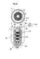
- the rotatable inner tube 4.1 is provided with openings 4.2, which are edgewise arranged rectangular openings in the embodiment.
- the openings are arranged one above the other in rows, which are at a small distance from each other in the longitudinal direction of the tube 4.1.
- Within each peripheral portion can be distributed over the circumference at least two, but also more than two such openings 4.2 be provided.
- the openings 4.2 of one row are offset from the openings 4.2 of the adjacent row in the circumferential direction of the tube 4.1.
- the openings 4.2 of each second row are at the same axial height.
- the offset of the openings 4.2 in the individual rows to each other is arbitrary.
- the shape of the openings 4.2, their number and their arrangement on the pipe 4.1 can be selected depending on the bulk material 3 to be dried. With the inner tube 4.1 it is ensured that the bulk material 3 is not flowed through uniformly over its height and its circumference by the drying medium, but in each case only partially. Since the pipe 4.1 is rotated about its axis, the drying medium passes at constantly changing locations in the bulk 3. The locations of the pipe 4.1 outside the openings 4.2 cover the openings of the surrounding pipe 4, so that the supplied via the line 12 drying medium only in the region of the openings 4.2 can flow radially outward into the bulk material 3.
- the tube 4.1 rotates about its axis during the drying / crystallization process, the entry of the drying medium into the bulk material 3 takes place at constantly changing points. As a result, not all of the bulk material 3 is acted upon by its height by the drying medium, so that that part of the bulk material, which is not currently traversed by dry air, remains at rest. As a result, a reliable slipping of the bulk material 3 is achieved, so that a reliable discharge of the bulk material is ensured via the outlet 8.
- the drying medium can be fed at high speed to the bulk material 3, so that the drying time is considerably shortened. This is also helped by the fact that the bulk material flows through its height radially from the dry medium.
- Fig. 1 for which shows an opening 4.2 by rotating the tube 4.1 in the direction of arrow the emerging drying medium flow 110 is passed over 360 ° in the bulk material 3.
- the openings in the tube 4 are covered by the tube 4.1, so that at these locations no drying medium can get into the bulk material 3.
- the openings 4.2 arranged in several rows one above the other and are also arranged offset in the circumferential direction of the tube 4.1 against each other takes place in this way always a partial flow of the bulk material 3 through the drying medium, which emerges from the respective openings 4.2.
- Such a guidance of the drying medium achieves a particularly effective drying or crystallization of the bulk material which takes up little time.
- FIG. 1a shows, in each peripheral portion of the tube 4.1 each only one opening 4.2 is provided. Depending on the application, two or more openings 4.2 may be provided at a distance in the circumferential direction one behind the other in each circumferential section. Such a design of the tube 4.1 is suitable for a correspondingly large diameter of the tube 4.1 or 4 at.
- Fig. 1b shows a variant in which the drive 5.2 is in the container 1. At the in Fig. 1 illustrated embodiment, the drive is 5.2 outside the container.
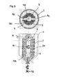
- the partial air supply over the height of the inner tube 4 and along its length can also be achieved if no rotatable inner tube 4.1 is used ( 2a and 2b ).
- at least one tubular aperture 4.3 is provided in the inner tube 4, which is axially movable within the tube 4.
- four spaced-apart tubular diaphragms 4.3 are provided in the tube 4, sitting on a common piston rod 111. With her, the aperture 4.3 can be moved axially together within the tube 4.
- the tubular panels have only a small distance from the inner wall of the tube 4, so that the aperture 4.3 can be reliably adjusted.
- the distance is so small or the area between the aperture 4.3 and the inner wall of the tube 4 sealed so that the supplied via the line 12 into the tube 4 drying medium is not between the Inner wall of the tube 4 and the aperture 4.3 can get.
- the drying medium can thus flow radially outwards into the bulk material 3 only through the openings of the tube 4 in the area between the superposed panels 4.3, as indicated by the flow arrows. Since the apertures 4.3 are axially adjustable in the tube 4, depending on the position of the aperture 4.3 different areas of the tube 4 are released for the passage of the drying medium.
- the piston rod 111 protrudes into a pneumatic cylinder 5.5, which is actuated by means of a switching valve 5.6.
- the piston 112 in the pneumatic cylinder 5.5 can be acted upon on both sides.
- the pressure medium is introduced via the working port A of the switching valve 5.6 in the pneumatic cylinder 5.5 so that the piston 112 is moved upwards.
- the pressure medium located in the other cylinder chamber is returned to the tank via the tank connection T of the switching valve 5.6.
- the sitting on the piston rod 111 aperture 4.3 are correspondingly in the in Fig. 2a adjusted upper position adjusted.
- the drying medium flows radially in the direction of the drawn flow arrows in the area between the diaphragms 4.3 through the tube 4 into the bulk material 3.
- the switching valve 5.6 If the switching valve 5.6 is switched over ( Fig. 2b ), the pressurized medium passes into the upper cylinder space, whereby the piston 112 is displaced downwards. The pressure medium in the lower cylinder chamber is returned to the tank. About the piston rod 111, the aperture 4.3 are adjusted to the other end position in which the aperture 4.3 in accordance with the switching position Fig. 2a cover exposed areas of the tube 4. The drying medium now flows over those areas of the tube 4 in the bulk material 3, in accordance with the switching position Fig. 2a were covered by the panels.
- the bulk material 3 is again applied only in some areas with the drying medium.
- the switching valve 5.6 can be switched at the same time intervals in each case to the aperture 4.3 in the position according to Fig. 2a or in the position according to Fig. 2b to adjust. Depending on the bulk material 3, it is also possible to switch the switching valve 5.6 in alternating time intervals.
- the distance between the adjacent apertures 4.3 advantageously corresponds to the width of the apertures 4.3. It is thereby achieved that, depending on the switching position, those regions of the pipe 4 are always covered, through which the drying medium has flowed into the bulk material 3 in the respective other switching position.
- the piston rod 111 protrudes through the outlet 8 of the container 1 to the outside.
- the piston rod 111 is completely within the tube 4.
- the pneumatic cylinder 5.5 is provided within the tube 4 at its lower end. Only the switching valve 5.6 is outside the container 1.
- the provided for actuating the double-acting piston 112 112 provided lines 113, 114 for the pressure medium are sealed by the switching valve 5.6 out through the ceiling 103 to the pneumatic cylinder 5.5.
- the lines 113, 114 are sealed out through the annulus 104 into the tube 4.
- the switching valve 5.6 is preferably a 4/2-way valve. With him, the piston 112 and thus the piston rod 111 can be moved reliably between the two end positions.
- the embodiment is according to Fig. 2c the same design as the embodiment according to the Fig. 2a and 2b ,
- the embodiment according to the Fig. 3 and 3a is advantageously used for the crystallization or for a better mixing in the drying of the bulk material 3.
- the tube 4 itself is rotated about its axis.
- the supplied via the line 12 drying medium is passed into the interior of the tube 4 and flows through the openings of the tube over the axial height radially into the bulk material 3.
- the tube 4 can over its entire height and over its entire circumference with the passage openings for the Be provided dry medium.
- the perforations may be provided, for example, over the same pitch circle, viewed in the axial direction, on the pipe.
- the tube 4 is closed at the bottom by a bottom 115 which sits on the shaft 5.3, which is rotated by the drive 5.2 about its axis.
- the drive 5.2 is located outside of the container 1, wherein the Shaft 5.3 protrudes through the outlet 8 to the outside.
- the drive 5.2 can also according to the embodiment according to the Fig. 1 a and 1 b be disposed within the tube 4.
- the tube 4 is rotatably mounted at the upper end by means of a stub shaft 116 in a bearing 117, which is advantageously a rolling bearing.
- the bearing 117 is disposed within a hood 118 which covers the tube 4 at the upper end and to which the conduit 12 for supplying the drying medium is connected.
- the embodiment according to Fig. 3a differs from the embodiment according to Fig. 3 merely in that the tube 4a has a larger diameter than in the embodiment according to Fig. 3 , Since the outer perforated pipe 2 has the same diameter as in the previous embodiment, the annular space 104 for the bulk material 3 has a relatively small radial width. This reduction in the radial width of the annular space 4 brings advantages for special bulk materials. Due to the larger diameter of the tube 4a and the narrower annular space 104, the relative movement of the bulk material 3 between the two tubes 2, 4a larger. As a result, agglomerates which could form during the crystallization of the bulk material 3 are avoided or agglomerates formed are removed again.
- Different bulk materials to be converted from amorphous to crystalline state in a device by a heat treatment may be very different in physical properties in the conversion phase from each other.
- Other bulk materials are also pure amorphous commodities with low dust content and cylindrical or spherical regular granules in small (2-3 mm) grains or large grains up to 4 to 5 mm maximum lengths, which have a very high bulk density.
- the annulus may be rather broad to increase the amount of material in the annulus. This measure causes a longer residence time of the material in the annulus, which is needed for larger material thicknesses to dry it.
- Special bulk materials are also regrinds of films or bottles, which behave very differently in the bed.
- film-grinding products of flat films can become very problematic, for example, if the film chips lay flat on one another, thereby making the air passage more difficult.
- the heating and the crystallization rate are then irregular.
- a smaller distance between the two tubes 2, 4, 4a can certainly be helpful in order to better mix the particles by a stronger movement in the material.
- the embodiment is according to Fig. 3a the same design as the embodiment according to Fig. 3 ,
- the embodiment according to Fig. 4 essentially corresponds to the embodiment according to Fig. 3 ,
- the rotatably driven by means of the drive 5.2 inner tube 4 is provided on its outer side with impellers 4b, which protrude radially from the tube shell and extend into the bulk material 3.
- the stirring vanes 4b are located one above the other in the axial direction of the tube 4 at a distance.
- the axially adjacent stirring vanes 4b are advantageously arranged angularly offset from each other.
- two or more stirring vanes 4b can be arranged distributed over the circumference at the same axial height. In principle, however, it is sufficient if only one stirring blade 4b is provided in each axial height.
- the arrangement and distribution of the impeller 4b is chosen so that a uniform mixing of the bulk material 3 over the height of the tube 4 is possible.
- 2 transversely projecting wings 2a are provided on the inside of the outer tube, which are stationary and are arranged so that they lie in the region between axially adjacent stirring blades 4b of the inner tube 4.
- the stirring vanes 4b and the stationary wings 2a are so long that they advantageously overlap one another, seen in the axial direction of the two tubes 2, 4.
- the stationary wings 2 are advantageously arranged distributed uniformly over the circumference.
- the fixed wings 2a prevent the bulk material 3 is rotated by the rotating tube 4.
- the bulk material 3 is optimally mixed and reliably prevents the formation of agglomerates in the bulk material.
- the stirring blades 4b By the stirring blades 4b, the bulk material 3 is again only partially loosened and moved. As a result, the drying medium emerging from the inner tube 4 can dry the bulk material 3 to the required extent within a short time.
- the wings 2a, 4b may be formed differently.
- the wings 2a, 4b may be formed differently.
- bars in wing shape can be used for the wings.
- Fig. 5 shows an embodiment in which the drying medium is introduced via the stirring blades 4c in the bulk material 3.
- the tube 4 may be formed without perforation.
- the jacket of the tube 4 is completely perforated or only partially provided with a perforation.
- the stirring vanes 4c protrude close to the inner wall of the outer tube 2, so that the drying medium emerging from the stirring vanes 4c completely captures the bulk material 3 in the ring 104.
- the impellers 4c are provided with a flat cross section ( Fig. 5 ), so that the stirring vanes have a substantially greater width in relation to their thickness measured in the axial direction of the tube 4.
- the stirring blades 4c are provided with outlet openings 121, via which the drying medium emerges into the bulk material 3.
- the outlet openings may also be provided in the top and bottom of the impeller 4c. In this case, 4c corresponding outlet openings for the drying medium are present on all four sides of the impeller. The outlet openings may also be provided only on each of the sides of the agitator 4c.
- the radially outer ends of the stirring blades 4c are closed.
- the radially inner ends are open to the interior of the inner tube 4, so that the inflowing via the line 12 drying medium can get into the agitator 4c.
- the outlet openings 121 may be, for example, round openings or slots through which the drying medium flows into the bulk material 3.
- the stationary wings 2a are provided, which are provided in the same manner as in the previous embodiment of the tube 2 and arranged with respect to the stirring vanes 4c.
- the agitating blades 4c are provided diametrically opposite one another at the same axial height of the tube 4 by way of example. If the pipe 4 with the Drive 5.2 rotated about its axis, the bulk material 3 is partially moved by the agitator 4c. In cooperation with the stationary wings 2a prevents the bulk material 3 is rotated by the rotation of the inner tube 4 in rotation.
- the drying medium does not reach the bulk material 3 at the same time over the entire circumference and the axial height of the tube 4, but only partially in the region in which the stirring vanes 4c are located within the bulk material 3. As in the previous embodiments, a portion of the bulk material 3 is at rest, which is reliably achieved that the bulk material 3 can slip properly. Due to the partial entry of the drying medium, it is possible to introduce the drying medium at a particularly high speed in the bulk material 3, whereby the drying time is significantly reduced.
- the driving force is additionally reduced by the rotating inner tube 4, since around the agitator 4c around a vortex zone arises in which the amount of the drying medium is correspondingly high.
- the contact between the drying medium and the bulk material 3 as a result of the partial entry of the drying medium is considerably better than when the drying medium is introduced uniformly over the entire height and the entire circumference of the inner tube 4 in the bulk material 3.
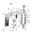
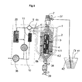
- Fig. 6 shows a plant with which the drying speed can be increased considerably. This is achieved in that the vapor pressure difference between the drying medium and the bulk material 3 to be dried is increased. To achieve this, the bulk material 3 is placed in phases under a negative pressure. The bulk material 3 in the annular space 104 between the outer tube 2 and the inner tube 4 is flowed through in a first phase by the exiting the tube 4 drying medium at high speed. Subsequently, the bulk material 3 is exposed to a negative pressure in a second phase for a certain time. By This alternating process is achieved that the drying process is greatly accelerated.
- Fig. 6 The system according to Fig. 6 is basically the same design as the plant after Fig. 1 , In order to generate the negative pressure, corresponding valves are present, which will be described in more detail below.
- the drying medium is supplied by means of the blower 10 via a valve 31 of the heater 11, with which the drying medium is heated to the drying temperature if necessary.
- the drying medium Via the line 12, the drying medium enters the inner tube 4, which is a perforated tube in this embodiment.
- the drying medium enters the bulk material 3 via the height and circumference of the tube 4.
- the drying medium absorbs the moisture from the bulk material 3.
- the drying medium flows through the perforated outer tube 2 and enters the annular space 108 between the tube 2 and the container shell.
- the moisture laden drying medium flows via the return line 6 and the filter 9 back to the blower 10, which directs the return air via the open valve 31 into the conduit 12.
- a portion of the return air passes in the flow direction behind the filter 9 in the conduit 21 in which a valve 33 is seated.
- this part of the return air in the basis of Fig. 1 explained manner via the heat exchanger 22 and the radiator 23 to the dehumidifier 20 flow.
- the return air is dehumidified and passed through the line 24 and the heat exchanger 22 back to the return line 6.
- the dried return air passes through the fan 10 and the heater 11 in the inner tube 4.
- a valve 32 which is open in the described cycle.
- valve 35 At the outlet of the filling device 7 is another valve 35, with which the filling device 7 can be shut off, so that no bulk material 3 can be refilled into the container 1.
- a further valve 34 is provided, with which the outlet 8 can be opened and closed valve-controlled.
- the line 122 adjoining the pressure side of the blower 10, from which the line 12 branches off, can be closed in the flow direction behind the connection of the line 12 by a valve 30.
- the valve 30, which connects the system to the environment is closed.
- the drying phase described is replaced in certain cycles by the negative pressure phase.
- a negative pressure in the system is generated by means of the blower 10.
- the valves 31 to 35 are closed and the valve 30 is opened.
- the fan 10 promotes the air from the conduit system and the container 1 via the open valve 30 to the outside. This creates in the entire flow space within the system and thus also within the annular space 104, in which the bulk material 3 is, a negative pressure. He will be maintained for a certain time.
- the valve 31 is opened to reduce the negative pressure in the system. Then, the valves 32 and 33 can be opened while the valve 30 is closed. Then again, the drying of the bulk material 3 by means of the drying medium, which is passed via the line 12 into the inner tube 4.
- the two tubes 2, 4 are formed as perforated tubes.
- the drying medium which passes via the supply line 12 into the inner tube 4, flows radially over the height and over the circumference of the inner tube 4 and flows through the bulk material located in the annular space 104.
- the drying medium absorbs the moisture from the bulk material 3 and passes through the openings of the outer tube 2 in the annular space 108. From here, the air flows in the manner described in the return line. 6
- the system according to Fig. 7 has the container 1 with the two tubes 2, 4, which are each formed as perforated pipes.
- the drying medium is passed via the line 12 into the tube 4 and exits from it radially into the bulk material 3. It lies in the annular space 104 between the two tubes 2, 4.
- the drying medium absorbs the moisture from the bulk material 3, flows through the outer tube 2 and enters the annular space 108 through which the moisture laden drying medium via the line 6 and the filter 9 is supplied in the blower 10.
- Part of this return air flows via the line 21 into the humidifying device 20, in which this part of the return air is dehumidified.
- the dehumidified return air is fed back to the line 6 on the suction side of the blower 10.
- the drying medium flows through the heating device 11, with which it is heated to the required drying temperature, if necessary, before entering the tube 4.
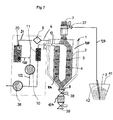
- the system according to Fig. 7 has the additional blower 36, with which a negative pressure can be generated within the system.
- the blower 36 is connected to the line 122 and associated with the filling device 7 and produces the necessary negative pressure for the conveyance of bulk material. Since drying medium is still present in the process circuit in the vacuum state, the drying medium can continue to be circulated by means of the blower 10 in order to heat the bulk material 3 and thereby dehumidify it.
- the negative pressure which acts simultaneously, increases the vapor pressure difference between the drying medium and the bulk material to be dried 3.
- the fan 36 promotes the air present in the system at its pressure side in the environment until the desired negative pressure in the system is present.
- a suction lance 42 is connected via a suction line 123, which is introduced into a container 41 loaded with the bulk material 3.
- a suction line 123 is introduced into a container 41 loaded with the bulk material 3.
- any other bulk material source can be used.
- the suction line 123 is connected via a valve 37 to the filling device 7.
- the valve 37 is opened. About the blower 36, the bulk material 3 is sucked from the container 41 by means of the suction lance 42 in the filling device 7. Preferably, the bulk material 3 is conveyed until the filling device 7 is filled. Then the valve 37 is closed. Then, the valve (not shown) is opened at the outlet of the filling device 7, so that the bulk material can flow from the filling device 7 into the annular space 104.
- valves 38 and 39 are connected, which form a lock for the bulk material 3 removed from the container 1.
- the valve 39 is closed and the valve 38 is opened. Then the bulk material can get into a gap 124 between the two valves 38, 39.
- the valve 38 is closed and the valve 39 is opened. The bulk material arrives from the gap 124, for example, in a processing machine.
- the lock in the form of the two valves 38, 39 allows the bulk material to be removed from the container 1, while negative pressure is applied in the system.
- the bulk material 3 removed from the container 1 can be supplied, for example, to a processing machine, instead of the lock described, it is also possible, for example, to use a rotary valve which permits a continuous flow of bulk material.
- the negative pressure is additionally and simultaneously used for drying the bulk material by means of the drying medium.
- the negative pressure takes place in conjunction with the filling device 7, which always operates for filling the container 1 with negative pressure.
- the filling device 7 is connected to the suction side of the blower 36, so that the bulk material 3 is sucked out of the container 41.
- the negative pressure generated thereby also acts in the annular space 104, in which the bulk material 3 is in the container 1 for the drying process.
- the two tubes 2, 4 are formed as perforated pipes.
- the drying medium conducted via the line 12 into the inner tube 4 flows through the bulk material 3 in the annular space 104 and passes through the openings of the outer tube 2 into the annular space 108. From here, the moisture laden drying medium flows into the return line 6.
- FIG. 8 a plant in which the inner tube 4 according to the embodiment according to the Fig. 1 . 1a and 1b is rotatable about its axis.
- the drive for the tube 4 can outside the container 1, but also within the container 1 ( Fig. 1 b) be provided.
- the bulk material 3 in the annular space 104 between the two tubes 2, 4 flows through the drying medium in phases.
- Fig. 8 can for the inner tube 4 and a training according to the Fig. 2a to 2c and according to the Fig. 3 and 3a be used.
- the tube 4 according to the Fig. 3 and 3a There is the advantage that in particular in the crystallization of thermoplastic polyesters volatile components can escape from the material. This can be the process of a post-condensation in the plant, in which the molecular chains of the polyester extend again and acetaldehyde is expelled from the bulk material.
- a pipe accordingly Fig. 4 can be used, in which the rotating inner tube 4 with the tube wings 4b and the outer tube 2 is provided with the stationary wings 2a.
- a pipe accordingly Fig. 4 can be used, in which the rotating inner tube 4 with the tube wings 4b and the outer tube 2 is provided with the stationary wings 2a.
- the training of the inner tube 4 according to Fig. 5 at the plant according to Fig. 8 use.
- the drying medium emerging from the impellers 4c may be combined with the application of the described negative pressure.
- the temperature sensor 50 is provided in the line 12, with the aid of which the drying process can be controlled very easily. With the temperature sensor 50, the temperature of the introduced into the tube 4 drying medium is detected.
- the reference temperature is the temperature of the bulk material 3 at the outlet of the container 1. Both the temperature of the bulk material at the container outlet and the temperature of the incoming drying medium are detected. As a result, the temperature of the drying medium can be easily controlled or regulated so that the bulk material 3 in the container 1 is not heated inadmissibly high.
- the temperature sensor 50 may be provided at any suitable location within the system.
- the heating device 11 is controlled or regulated in accordance with the detected temperatures of the drying medium and the bulk material at the container outlet, so that the drying medium always has the temperature required for optimal drying of the bulk material 3.
- the drying medium is supplied via the inner tube and enters after flowing through the bulk material 3 through the passage openings of the outer tube 2 into the annular space 108 a. From here, the return air enters the return line. 6
- the drying medium can flow in the described embodiments, the bulk material 3 but also in the opposite direction. Accordingly, the tubes 2, 4 and the internals are arranged and formed so that the drying medium can flow through the outer tube 2 into the bulk annulus 104. After flowing through the bulk material 3 passes the drying medium in the inner tube 4 and is fed from there to the return line 6.
- FIGS Fig. 9a and 9b An exemplary embodiment of such a drying container show the Fig. 9a and 9b , This embodiment is similar to the embodiment according to FIGS Fig. 2a and 2b ,
- the outer tube 2 is surrounded by at least one tubular aperture 4.3, which is axially movable.
- four spaced apart superimposed tubular aperture 4.3 are provided, which sit on the common piston rod 111. With her, the aperture 4.3 can be moved together axially along the outer tube 2.
- the tubular panels have only a small distance from the outer wall of the tube 2, so that the aperture 4.3 can be reliably adjusted.
- the distance is so small or the area between the aperture 4.3 and the outer wall of the tube 2 sealed so that the supplied drying medium can not get between the outer wall of the tube 2 and the aperture 4.3.
- the drying medium can flow only in the area between the superposed panels 4.3 through the openings of the tube 2 radially inwardly into the bulk material 3, as indicated by the flow arrows. Since the apertures 4.3 are axially adjustable along the tube 2, depending on the position of the aperture 4.3 different areas of the tube 2 are released for the passage of the drying medium.
- the drying medium is introduced into the annulus 108 between the outer tube 2 and the cylindrical shell 101 of the container 1.
- the piston rod 111 protrudes into the pneumatic cylinder 5.5, which is actuated by means of the switching valve 5.6.
- the piston 112 in the pneumatic cylinder 5.5 can be acted upon on both sides.
- the pressure medium is introduced via the working port A of the switching valve 5.6 in the pneumatic cylinder 5.5 so that the piston 112 is moved upwards.
- the pressure medium in the other cylinder chamber is over the tank connection T of the switching valve 5.6 returned to the tank.
- the sitting on the piston rod 111 aperture 4.3 are correspondingly in the in Fig. 9a adjusted upper position adjusted.
- the drying medium flows in the direction of the drawn flow arrows in the area between the aperture 4.3 through the tube 2 radially inwardly into the bulk material.
- the pressurized medium passes into the upper cylinder space, whereby the piston 112 is displaced downwards.
- the pressure medium in the lower cylinder chamber is returned to the tank.
- the aperture 4.3 are adjusted to the other end position in which the aperture 4.3 in accordance with the switching position Fig. 9a Cover exposed areas of the tube 2.
- the drying medium now flows over those areas of the tube 2 in the bulk material 3, in accordance with the switching position Fig. 9a were covered by the panels.
- the bulk material 3 is again applied only in some areas with the drying medium.
- the switching valve 5.6 as in the embodiment according to the Fig. 2a and 2b be switched at equal intervals to the aperture 4.3 in the position according to Fig. 9a or in the position according to Fig. 9b to adjust.
- the distance between the axially adjacent aperture 4.3 advantageously corresponds to the width of the aperture 4.3. It is thereby achieved that, depending on the switching position, those regions of the pipe 4 are always covered, through which the drying medium has flowed into the bulk material 3 in the respective other switching position.
- the piston rod 111 protrudes through the conical jacket 102 of the container 1 to the outside.
- the drying medium enters after flowing through the bulk material 3 in the inner tube 4 and is supplied from here via a line 125 of the return line 6.
- Fig. 10 shows a system that is designed substantially the same as the system according to Fig. 8 ,
- the two coaxial tubes 2, 4 are perforated tubes, so that the drying medium, which passes through the feed line 12 into the inner tube 4, can flow through the openings radially outwardly into the bulk material 3.
- the drying medium flows through the bulk material 3 radially and passes through the openings of the outer tube 2 to the outside in the annular space 108.
- the drying medium absorbs moisture and passes as return air into the return air line 6.
- the return air is sucked in by the blower 10 and flows through the filter 9 and is heated by the heater 11 before entering the drying container, if necessary.
- the drying medium is thus circulated via the line 6, the line 122 and the line 12 and in this case, if necessary, heated by means of the heating device 11.
- a portion of the return air is not diverted to the dehumidifier 20. Rather, dehumidified drying medium is introduced into the return line 6 in front of the blower 10 by the dehumidifier 20 via a line 126 if required.
- the valve 37 is opened.
- the bulk material 3 is sucked by means of the blower 36 from the container 41 by means of the suction lance 42 via the suction line 123.
- the valve 37 is opened so that the bulk material 3 can enter the annular space 104 between the two tubes 2, 4.
- the two valves 38, 39 and the intermediate space 124 between them are the lock at the outlet 8 of the drying container that the bulk material can be removed while applying negative pressure throughout the system.
- the container 41 is connected to the suction side of the blower 36, so that the bulk material 3 is sucked out of the container 41.
- the negative pressure generated thereby also acts in the annular space 104.
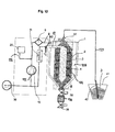
- Fig. 11 shows a system in which the bulk material 3 fills the interior of the drying container 1. In contrast to the previous embodiments are in the drying tank 1 no inner and outer tubes.
- the system according to Fig. 11 Incidentally, it is essentially the same design as the plant Fig. 10 ,
- the blower 10 is the drying medium conveyed via the heater 11 in the supply line 12. It protrudes into the middle of the drying container 1 and is directed inside the drying container 1 down.
- At the lower end of this vertical line section 12 ' is a downwardly directed funnel 13, which ends at a distance from the outlet 8 of the drying container and from which the drying medium emerges downwards.
- the drying medium marked by arrows flows downwards out of the funnel 13 into the bulk material 3.
- the drying medium flows through the bulk material 3 upwards and absorbs moisture from the bulk material.
- the drying medium flows out of the drying container 1 via the return line 6.
- the moisture-laden drying medium flows through the filter 9 and is then heated by the heating device 11 before it re-enters the drying container 1, if necessary.
- the temperature sensor 50 detects the temperature of the drying medium as it enters the drying tank 1 in the manner described.
- dehumidified air is fed to the return line 6 via the dehumidifier 20 and the line 126.
- the system works the same, as based on the Fig. 7 . 8th and 10 has been explained.
- the blower 36 With the blower 36, the negative pressure is generated in the system, which is additionally and simultaneously used for drying the bulk material.
- the simultaneous application of the negative pressure and the flow of the bulk material 3 through the drying medium again results in an excellent drying of the bulk material within a very short time.
- the negative pressure is generated by the blower 36, which also serves to fill the drying tank 1 with the bulk material 3.
- the negative pressure is also present in the closed heating circuit 6, 9, 10, 122, 11, 12, resulting in the optimum drying within a short time.
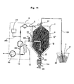
- the system shown corresponds to the system according to Fig. 10 ,
- the drying container 1 is connected to a processing machine 52, with which the bulk material 3 is processed.
- the bulk material 3 passes from the outlet 8 of the drying container 1 into a feed line 53 which supplies the bulk material 3 to a melting region 54 of the processing machine 52. Via this melting region 54, the bulk material passes into an extruder screw 55, with which the bulk material 3 is melted and passed into an injection mold 56 shown only schematically. With her from the melted bulk material 3 of the respective object is produced.
- Fig. 12 is only one embodiment, which is not to be understood as limiting the other embodiment of the system.
- the blower 36 In the embodiments according to the 6 to 12 is provided as a vacuum generator, the blower 36, with which the bulk material 3 is sucked into the drying tank 1.
- the negative pressure in the system can also be generated by any other negative pressure generating device.
Applications Claiming Priority (1)
| Application Number | Priority Date | Filing Date | Title |
|---|---|---|---|
| DE102013022092.0A DE102013022092A1 (de) | 2013-12-18 | 2013-12-18 | Trocknungsbehälter für Schüttgüter, insbesondere Kunststoffgranulat, sowie Verfahren zum Trocknen und/oder Kristallisieren von Schüttgut |
Publications (2)
| Publication Number | Publication Date |
|---|---|
| EP2886984A2 true EP2886984A2 (fr) | 2015-06-24 |
| EP2886984A3 EP2886984A3 (fr) | 2016-01-20 |
Family
ID=52144350
Family Applications (1)
| Application Number | Title | Priority Date | Filing Date |
|---|---|---|---|
| EP14004216.9A Withdrawn EP2886984A3 (fr) | 2013-12-18 | 2014-12-15 | Procédé de séchage et/ou de cristallisation de produits en vrac et installation d'exécution d'un tel procédé |
Country Status (5)
| Country | Link |
|---|---|
| US (1) | US20150176896A1 (fr) |
| EP (1) | EP2886984A3 (fr) |
| CN (1) | CN105043016A (fr) |
| BR (1) | BR102014031694A2 (fr) |
| DE (1) | DE102013022092A1 (fr) |
Cited By (3)
| Publication number | Priority date | Publication date | Assignee | Title |
|---|---|---|---|---|
| EP3702710A1 (fr) * | 2019-02-27 | 2020-09-02 | Wenz Kunststoff GmbH & Co. KG | Récipient de séchage et procédé de séchage de granulés en matière plastique |
| CN112066653A (zh) * | 2020-08-19 | 2020-12-11 | 杭州科永医疗科技有限公司 | 一种绿色医药生产处理用脱水装置 |
| CN115307388A (zh) * | 2022-08-16 | 2022-11-08 | 苏州倍丰智能科技有限公司 | 一种金属粉末冷干燥装置 |
Families Citing this family (5)
| Publication number | Priority date | Publication date | Assignee | Title |
|---|---|---|---|---|
| US9341410B1 (en) * | 2013-04-11 | 2016-05-17 | Gryphon Environmental, Llc | Apparatus for removing liquid from a suspension |
| CN107702511B (zh) * | 2017-11-23 | 2022-11-25 | 湖北金炉节能股份有限公司 | 一种内循环洁净型煤干燥机 |
| AT519978B1 (de) * | 2017-12-19 | 2018-12-15 | Sonderhoff Eng Gmbh | Vorrichtung zur Herstellung von Kunststoffteilen |
| CN212109328U (zh) * | 2019-09-30 | 2020-12-08 | 西马尔有限责任公司 | 用于处理塑料的设备 |
| CN117839563A (zh) * | 2024-03-07 | 2024-04-09 | 江苏泰禾金属工业有限公司 | 一种空心球状氧化亚铜软模板法干燥焙烧制备装置 |
Family Cites Families (13)
| Publication number | Priority date | Publication date | Assignee | Title |
|---|---|---|---|---|
| US3233334A (en) * | 1962-09-28 | 1966-02-08 | Pennsalt Chemicals Corp | Flash drying apparatus and method utilizing intermittent pulses of drying gas |
| US3597850A (en) * | 1970-03-11 | 1971-08-10 | Nat Service Ind Inc | Continuous vacuum drier |
| SE374811B (fr) * | 1973-01-18 | 1975-03-17 | Sintab Swedinventor Ab | |
| CA1327687C (fr) * | 1982-03-15 | 1994-03-15 | Jaro Kopernicky | Dispositif servant a eliminer les composants volatiles residuels contenus dans les matieres plastiques destinees a etre extrudees ou moulees par injection |
| DE4317768A1 (de) * | 1993-05-28 | 1994-12-01 | Somos Gmbh | Verfahren und Vorrichtung zum Aufbereiten eines insbesondere feuchten Adsortionsmittels |
| DE19840358A1 (de) * | 1998-09-04 | 2000-03-09 | Motan Holding Gmbh | Verfahren zum Heizen und/oder Trocknen von fließfähigem Schüttgut, vorzugsweise von Kunststoffgranulat, und Heizeinrichtung zur Durchführung des Verfahrens |
| US6270708B1 (en) * | 1999-03-12 | 2001-08-07 | Tamer International, Ltd. | Agglomerating and drying apparatus |
| ITVR20080024A1 (it) * | 2008-02-18 | 2009-08-19 | Moretto Spa | Struttura di tramoggia |
| IT1393150B1 (it) * | 2009-02-09 | 2012-04-11 | Schiavolin | Deumidificatore per materie plastiche |
| US8141270B2 (en) * | 2009-08-13 | 2012-03-27 | Maguire Products, Inc. | Gas flow rate determination method and apparatus and granular material dryer and method for control thereof |
| IT1401634B1 (it) * | 2010-08-03 | 2013-07-26 | Moretto Spa | Struttura di tramoggia, impianto di deumidificazione e procedimento di deumidificazione di materiale plastico granulare. |
| WO2012018320A1 (fr) * | 2010-08-04 | 2012-02-09 | Ima Life North America Inc. | Lyophilisation en vrac au moyen d'une congélation par pulvérisation et d'un séchage par agitation |
| CN102353238B (zh) * | 2011-08-01 | 2013-07-24 | 上海海事大学 | 间歇式真空微波干燥装置及其处理真空绝热板芯材的方法 |
-
2013
- 2013-12-18 DE DE102013022092.0A patent/DE102013022092A1/de not_active Withdrawn
-
2014
- 2014-12-15 EP EP14004216.9A patent/EP2886984A3/fr not_active Withdrawn
- 2014-12-17 BR BR102014031694A patent/BR102014031694A2/pt not_active Application Discontinuation
- 2014-12-18 CN CN201410858384.0A patent/CN105043016A/zh active Pending
- 2014-12-18 US US14/574,465 patent/US20150176896A1/en not_active Abandoned
Non-Patent Citations (1)
| Title |
|---|
| None |
Cited By (4)
| Publication number | Priority date | Publication date | Assignee | Title |
|---|---|---|---|---|
| EP3702710A1 (fr) * | 2019-02-27 | 2020-09-02 | Wenz Kunststoff GmbH & Co. KG | Récipient de séchage et procédé de séchage de granulés en matière plastique |
| EP3702710B1 (fr) | 2019-02-27 | 2021-11-10 | Wenz Kunststoff GmbH & Co. KG | Récipient de séchage et procédé de séchage de granulés en matière plastique |
| CN112066653A (zh) * | 2020-08-19 | 2020-12-11 | 杭州科永医疗科技有限公司 | 一种绿色医药生产处理用脱水装置 |
| CN115307388A (zh) * | 2022-08-16 | 2022-11-08 | 苏州倍丰智能科技有限公司 | 一种金属粉末冷干燥装置 |
Also Published As
| Publication number | Publication date |
|---|---|
| CN105043016A (zh) | 2015-11-11 |
| US20150176896A1 (en) | 2015-06-25 |
| DE102013022092A1 (de) | 2015-06-18 |
| BR102014031694A2 (pt) | 2016-06-28 |
| EP2886984A3 (fr) | 2016-01-20 |
Similar Documents
| Publication | Publication Date | Title |
|---|---|---|
| EP2886984A2 (fr) | Procédé de séchage et/ou de cristallisation de produits en vrac et installation d'exécution d'un tel procédé | |
| EP2286973B1 (fr) | Procédé et dispositif destinés au traitement de matériaux synthétiques | |
| EP2876395B1 (fr) | Dispositif et procédé de séchage de matières à sécher | |
| EP2984429B1 (fr) | Séchoir à bande transporteuse comportant une chambre de séchage et une chambre de refroidissement | |
| EP2326900B1 (fr) | Procédé et dispositif de séchage de biomasse | |
| DE19840358A1 (de) | Verfahren zum Heizen und/oder Trocknen von fließfähigem Schüttgut, vorzugsweise von Kunststoffgranulat, und Heizeinrichtung zur Durchführung des Verfahrens | |
| DE4138997A1 (de) | Vorrichtung zum dragieren von stueckigen produkten, insbesondere pillen und tabletten | |
| DE2249863A1 (de) | Vorrichtung zum dragieren von pillen, tabletten, granulaten und dergleichen | |
| EP2114176B1 (fr) | Dispositif et procédé pour le traitement thermique d'un produit végétal en vrac | |
| WO1991006364A1 (fr) | Dispositif pour l'agitation de particules solides | |
| DE102007028912A1 (de) | Verfahren und Vorrichtung zum Trocknen von Granulaten oder Pellets | |
| EP3708936B1 (fr) | Procédé de recyclage de polyoléfines | |
| WO2010057695A9 (fr) | Postcondensation de granulé de plastique | |
| EP0610789A1 (fr) | Dispositif pour éliminer les bactéries et les germes | |
| WO2002030555A9 (fr) | Procede et dispositif pour le traitement thermique d'un materiau se presentant sous forme pulverulente ou granulee | |
| DE202013101746U1 (de) | Trockner zum Trocknen von Trocknungsgut mittels warmer Trocknungsluft | |
| EP0660059B1 (fr) | Dispositif pour sécher du matériau en vrac | |
| DE2745179C2 (de) | Vorrichtung zum chargenweisen Mischen, Trocknen und/oder Granulieren rieselfähiger Schüttgüter mit breitem Partikelspektrum | |
| EP3546382B1 (fr) | Barre diffusant de la vapeur et tunnel de rétraction | |
| DE2343708A1 (de) | Verfahren und vorrichtung zur herstellung von kunststoffen | |
| DE19902458A1 (de) | Vorrichtung und Verfahren zum Behandeln von Kunststoffmaterial | |
| DE102006016534A1 (de) | Vorrichtung sowie Apparatur und Verfahren zur Behandlung von Materialien bei erhöhter Temperatur und unter Bewegung und unter Vakuum | |
| WO2019154912A1 (fr) | Dispositif de traitement continu d'aliments solides pour humains et d'aliments solides pour animaux et d'autres produits en vrac, muni d'un dispositif de traitement thermique pour réaliser un traitement thermique continu | |
| WO2002047810A1 (fr) | Dispositif de purification et / ou de decontamination de polyester | |
| EP0331111B1 (fr) | Appareil du type à lit fluidisé, spécialement pour la granulation d'une matière pulvérulente |
Legal Events
| Date | Code | Title | Description |
|---|---|---|---|
| PUAI | Public reference made under article 153(3) epc to a published international application that has entered the european phase |
Free format text: ORIGINAL CODE: 0009012 |
|
| 17P | Request for examination filed |
Effective date: 20141215 |
|
| AK | Designated contracting states |
Kind code of ref document: A2 Designated state(s): AL AT BE BG CH CY CZ DE DK EE ES FI FR GB GR HR HU IE IS IT LI LT LU LV MC MK MT NL NO PL PT RO RS SE SI SK SM TR |
|
| AX | Request for extension of the european patent |
Extension state: BA ME |
|
| PUAL | Search report despatched |
Free format text: ORIGINAL CODE: 0009013 |
|
| AK | Designated contracting states |
Kind code of ref document: A3 Designated state(s): AL AT BE BG CH CY CZ DE DK EE ES FI FR GB GR HR HU IE IS IT LI LT LU LV MC MK MT NL NO PL PT RO RS SE SI SK SM TR |
|
| AX | Request for extension of the european patent |
Extension state: BA ME |
|
| RIC1 | Information provided on ipc code assigned before grant |
Ipc: F26B 21/10 20060101ALI20151217BHEP Ipc: F26B 5/04 20060101ALI20151217BHEP Ipc: F26B 17/12 20060101AFI20151217BHEP |
|
| R17P | Request for examination filed (corrected) |
Effective date: 20160720 |
|
| RBV | Designated contracting states (corrected) |
Designated state(s): AL AT BE BG CH CY CZ DE DK EE ES FI FR GB GR HR HU IE IS IT LI LT LU LV MC MK MT NL NO PL PT RO RS SE SI SK SM TR |
|
| 17Q | First examination report despatched |
Effective date: 20170619 |
|
| GRAP | Despatch of communication of intention to grant a patent |
Free format text: ORIGINAL CODE: EPIDOSNIGR1 |
|
| INTG | Intention to grant announced |
Effective date: 20200302 |
|
| STAA | Information on the status of an ep patent application or granted ep patent |
Free format text: STATUS: THE APPLICATION IS DEEMED TO BE WITHDRAWN |
|
| 18D | Application deemed to be withdrawn |
Effective date: 20200714 |