EP3708936B1 - Procédé de recyclage de polyoléfines - Google Patents
Procédé de recyclage de polyoléfines Download PDFInfo
- Publication number
- EP3708936B1 EP3708936B1 EP19163075.5A EP19163075A EP3708936B1 EP 3708936 B1 EP3708936 B1 EP 3708936B1 EP 19163075 A EP19163075 A EP 19163075A EP 3708936 B1 EP3708936 B1 EP 3708936B1
- Authority
- EP
- European Patent Office
- Prior art keywords
- polyolefin
- treatment
- granulate
- process according
- cooling medium
- Prior art date
- Legal status (The legal status is an assumption and is not a legal conclusion. Google has not performed a legal analysis and makes no representation as to the accuracy of the status listed.)
- Active
Links
- 229920000098 polyolefin Polymers 0.000 title claims description 126
- 238000000034 method Methods 0.000 title claims description 42
- 238000004064 recycling Methods 0.000 title claims description 10
- 239000008187 granular material Substances 0.000 claims description 142
- 239000000463 material Substances 0.000 claims description 69
- 239000002826 coolant Substances 0.000 claims description 58
- 239000007788 liquid Substances 0.000 claims description 42
- 230000008569 process Effects 0.000 claims description 31
- XLYOFNOQVPJJNP-UHFFFAOYSA-N water Substances O XLYOFNOQVPJJNP-UHFFFAOYSA-N 0.000 claims description 28
- 238000000926 separation method Methods 0.000 claims description 25
- 238000001125 extrusion Methods 0.000 claims description 17
- 238000001035 drying Methods 0.000 claims description 11
- 230000008018 melting Effects 0.000 claims description 10
- 238000002844 melting Methods 0.000 claims description 10
- 238000004140 cleaning Methods 0.000 claims description 8
- 229920000642 polymer Polymers 0.000 claims description 8
- 238000004519 manufacturing process Methods 0.000 claims description 7
- 238000007872 degassing Methods 0.000 claims description 5
- 229910052799 carbon Inorganic materials 0.000 claims description 3
- 238000002203 pretreatment Methods 0.000 claims description 3
- 238000001914 filtration Methods 0.000 claims description 2
- 238000005406 washing Methods 0.000 claims description 2
- 239000007789 gas Substances 0.000 description 89
- 238000005469 granulation Methods 0.000 description 31
- 230000003179 granulation Effects 0.000 description 31
- 239000003570 air Substances 0.000 description 30
- 238000001816 cooling Methods 0.000 description 15
- 239000002245 particle Substances 0.000 description 12
- 238000010438 heat treatment Methods 0.000 description 8
- -1 polyethylene Polymers 0.000 description 8
- 238000003860 storage Methods 0.000 description 7
- 239000000126 substance Substances 0.000 description 7
- 239000000047 product Substances 0.000 description 6
- 239000004698 Polyethylene Substances 0.000 description 5
- 229920000573 polyethylene Polymers 0.000 description 5
- IJGRMHOSHXDMSA-UHFFFAOYSA-N Atomic nitrogen Chemical compound N#N IJGRMHOSHXDMSA-UHFFFAOYSA-N 0.000 description 4
- 150000001336 alkenes Chemical class 0.000 description 4
- 238000009835 boiling Methods 0.000 description 4
- 125000004432 carbon atom Chemical group C* 0.000 description 4
- 238000001704 evaporation Methods 0.000 description 4
- 239000000155 melt Substances 0.000 description 4
- 239000004033 plastic Substances 0.000 description 4
- 229920003023 plastic Polymers 0.000 description 4
- 239000002002 slurry Substances 0.000 description 4
- LYCAIKOWRPUZTN-UHFFFAOYSA-N Ethylene glycol Chemical compound OCCO LYCAIKOWRPUZTN-UHFFFAOYSA-N 0.000 description 3
- 239000004743 Polypropylene Substances 0.000 description 3
- 230000015572 biosynthetic process Effects 0.000 description 3
- 238000009826 distribution Methods 0.000 description 3
- 230000008020 evaporation Effects 0.000 description 3
- 238000011049 filling Methods 0.000 description 3
- 235000013305 food Nutrition 0.000 description 3
- 239000011261 inert gas Substances 0.000 description 3
- 239000000203 mixture Substances 0.000 description 3
- 239000000178 monomer Substances 0.000 description 3
- 229920001155 polypropylene Polymers 0.000 description 3
- XKRFYHLGVUSROY-UHFFFAOYSA-N Argon Chemical compound [Ar] XKRFYHLGVUSROY-UHFFFAOYSA-N 0.000 description 2
- QQONPFPTGQHPMA-UHFFFAOYSA-N Propene Chemical compound CC=C QQONPFPTGQHPMA-UHFFFAOYSA-N 0.000 description 2
- 230000008859 change Effects 0.000 description 2
- 238000005520 cutting process Methods 0.000 description 2
- 239000007857 degradation product Substances 0.000 description 2
- 238000009792 diffusion process Methods 0.000 description 2
- 238000006073 displacement reaction Methods 0.000 description 2
- 239000012770 industrial material Substances 0.000 description 2
- XMGQYMWWDOXHJM-UHFFFAOYSA-N limonene Chemical compound CC(=C)C1CCC(C)=CC1 XMGQYMWWDOXHJM-UHFFFAOYSA-N 0.000 description 2
- 229910052757 nitrogen Inorganic materials 0.000 description 2
- 239000006174 pH buffer Substances 0.000 description 2
- JTJMJGYZQZDUJJ-UHFFFAOYSA-N phencyclidine Chemical class C1CCCCN1C1(C=2C=CC=CC=2)CCCCC1 JTJMJGYZQZDUJJ-UHFFFAOYSA-N 0.000 description 2
- 238000010008 shearing Methods 0.000 description 2
- 239000007787 solid Substances 0.000 description 2
- 238000007711 solidification Methods 0.000 description 2
- 230000008023 solidification Effects 0.000 description 2
- 241000143637 Eleocharis confervoides Species 0.000 description 1
- VGGSQFUCUMXWEO-UHFFFAOYSA-N Ethene Chemical compound C=C VGGSQFUCUMXWEO-UHFFFAOYSA-N 0.000 description 1
- 238000005299 abrasion Methods 0.000 description 1
- 238000010521 absorption reaction Methods 0.000 description 1
- 239000013543 active substance Substances 0.000 description 1
- 239000000654 additive Substances 0.000 description 1
- 150000001298 alcohols Chemical class 0.000 description 1
- 239000012080 ambient air Substances 0.000 description 1
- 150000001412 amines Chemical class 0.000 description 1
- 229910052786 argon Inorganic materials 0.000 description 1
- 125000003118 aryl group Chemical group 0.000 description 1
- QVGXLLKOCUKJST-UHFFFAOYSA-N atomic oxygen Chemical compound [O] QVGXLLKOCUKJST-UHFFFAOYSA-N 0.000 description 1
- 235000013361 beverage Nutrition 0.000 description 1
- 239000000872 buffer Substances 0.000 description 1
- 239000003054 catalyst Substances 0.000 description 1
- 238000007084 catalytic combustion reaction Methods 0.000 description 1
- 150000001875 compounds Chemical class 0.000 description 1
- 238000007906 compression Methods 0.000 description 1
- 230000006835 compression Effects 0.000 description 1
- 239000000356 contaminant Substances 0.000 description 1
- 238000011109 contamination Methods 0.000 description 1
- 229920001577 copolymer Polymers 0.000 description 1
- 239000000428 dust Substances 0.000 description 1
- 230000000694 effects Effects 0.000 description 1
- 238000005516 engineering process Methods 0.000 description 1
- 239000003337 fertilizer Substances 0.000 description 1
- 239000010794 food waste Substances 0.000 description 1
- 235000015203 fruit juice Nutrition 0.000 description 1
- 230000005484 gravity Effects 0.000 description 1
- 230000036541 health Effects 0.000 description 1
- 229920001519 homopolymer Polymers 0.000 description 1
- 229930195733 hydrocarbon Natural products 0.000 description 1
- 150000002430 hydrocarbons Chemical class 0.000 description 1
- 235000001510 limonene Nutrition 0.000 description 1
- 229940087305 limonene Drugs 0.000 description 1
- 239000008267 milk Substances 0.000 description 1
- 235000013336 milk Nutrition 0.000 description 1
- 210000004080 milk Anatomy 0.000 description 1
- 239000012768 molten material Substances 0.000 description 1
- 238000000465 moulding Methods 0.000 description 1
- 238000006386 neutralization reaction Methods 0.000 description 1
- 229910052756 noble gas Inorganic materials 0.000 description 1
- 150000002835 noble gases Chemical class 0.000 description 1
- 239000002736 nonionic surfactant Substances 0.000 description 1
- JRZJOMJEPLMPRA-UHFFFAOYSA-N olefin Natural products CCCCCCCC=C JRZJOMJEPLMPRA-UHFFFAOYSA-N 0.000 description 1
- 239000003960 organic solvent Substances 0.000 description 1
- 239000001301 oxygen Substances 0.000 description 1
- 229910052760 oxygen Inorganic materials 0.000 description 1
- 238000005192 partition Methods 0.000 description 1
- 235000011837 pasties Nutrition 0.000 description 1
- 230000000379 polymerizing effect Effects 0.000 description 1
- 235000015504 ready meals Nutrition 0.000 description 1
- 230000009467 reduction Effects 0.000 description 1
- 230000001105 regulatory effect Effects 0.000 description 1
- 239000000344 soap Substances 0.000 description 1
- 239000002689 soil Substances 0.000 description 1
- 239000012265 solid product Substances 0.000 description 1
- 239000002904 solvent Substances 0.000 description 1
- 238000001228 spectrum Methods 0.000 description 1
- 150000003505 terpenes Chemical class 0.000 description 1
- 235000007586 terpenes Nutrition 0.000 description 1
- 150000003573 thiols Chemical class 0.000 description 1
- 231100000331 toxic Toxicity 0.000 description 1
- 230000002588 toxic effect Effects 0.000 description 1
- 231100000419 toxicity Toxicity 0.000 description 1
- 230000001988 toxicity Effects 0.000 description 1
- 238000011144 upstream manufacturing Methods 0.000 description 1
- 235000013618 yogurt Nutrition 0.000 description 1
Images

Classifications
-
- C—CHEMISTRY; METALLURGY
- C08—ORGANIC MACROMOLECULAR COMPOUNDS; THEIR PREPARATION OR CHEMICAL WORKING-UP; COMPOSITIONS BASED THEREON
- C08J—WORKING-UP; GENERAL PROCESSES OF COMPOUNDING; AFTER-TREATMENT NOT COVERED BY SUBCLASSES C08B, C08C, C08F, C08G or C08H
- C08J11/00—Recovery or working-up of waste materials
- C08J11/04—Recovery or working-up of waste materials of polymers
- C08J11/06—Recovery or working-up of waste materials of polymers without chemical reactions
-
- F—MECHANICAL ENGINEERING; LIGHTING; HEATING; WEAPONS; BLASTING
- F26—DRYING
- F26B—DRYING SOLID MATERIALS OR OBJECTS BY REMOVING LIQUID THEREFROM
- F26B3/00—Drying solid materials or objects by processes involving the application of heat
- F26B3/02—Drying solid materials or objects by processes involving the application of heat by convection, i.e. heat being conveyed from a heat source to the materials or objects to be dried by a gas or vapour, e.g. air
- F26B3/06—Drying solid materials or objects by processes involving the application of heat by convection, i.e. heat being conveyed from a heat source to the materials or objects to be dried by a gas or vapour, e.g. air the gas or vapour flowing through the materials or objects to be dried
- F26B3/08—Drying solid materials or objects by processes involving the application of heat by convection, i.e. heat being conveyed from a heat source to the materials or objects to be dried by a gas or vapour, e.g. air the gas or vapour flowing through the materials or objects to be dried so as to loosen them, e.g. to form a fluidised bed
-
- B—PERFORMING OPERATIONS; TRANSPORTING
- B29—WORKING OF PLASTICS; WORKING OF SUBSTANCES IN A PLASTIC STATE IN GENERAL
- B29B—PREPARATION OR PRETREATMENT OF THE MATERIAL TO BE SHAPED; MAKING GRANULES OR PREFORMS; RECOVERY OF PLASTICS OR OTHER CONSTITUENTS OF WASTE MATERIAL CONTAINING PLASTICS
- B29B9/00—Making granules
- B29B9/02—Making granules by dividing preformed material
- B29B9/06—Making granules by dividing preformed material in the form of filamentary material, e.g. combined with extrusion
- B29B9/065—Making granules by dividing preformed material in the form of filamentary material, e.g. combined with extrusion under-water, e.g. underwater pelletizers
-
- B—PERFORMING OPERATIONS; TRANSPORTING
- B29—WORKING OF PLASTICS; WORKING OF SUBSTANCES IN A PLASTIC STATE IN GENERAL
- B29B—PREPARATION OR PRETREATMENT OF THE MATERIAL TO BE SHAPED; MAKING GRANULES OR PREFORMS; RECOVERY OF PLASTICS OR OTHER CONSTITUENTS OF WASTE MATERIAL CONTAINING PLASTICS
- B29B13/00—Conditioning or physical treatment of the material to be shaped
- B29B13/06—Conditioning or physical treatment of the material to be shaped by drying
-
- B—PERFORMING OPERATIONS; TRANSPORTING
- B29—WORKING OF PLASTICS; WORKING OF SUBSTANCES IN A PLASTIC STATE IN GENERAL
- B29B—PREPARATION OR PRETREATMENT OF THE MATERIAL TO BE SHAPED; MAKING GRANULES OR PREFORMS; RECOVERY OF PLASTICS OR OTHER CONSTITUENTS OF WASTE MATERIAL CONTAINING PLASTICS
- B29B9/00—Making granules
- B29B9/16—Auxiliary treatment of granules
-
- F—MECHANICAL ENGINEERING; LIGHTING; HEATING; WEAPONS; BLASTING
- F26—DRYING
- F26B—DRYING SOLID MATERIALS OR OBJECTS BY REMOVING LIQUID THEREFROM
- F26B5/00—Drying solid materials or objects by processes not involving the application of heat
- F26B5/08—Drying solid materials or objects by processes not involving the application of heat by centrifugal treatment
-
- B—PERFORMING OPERATIONS; TRANSPORTING
- B29—WORKING OF PLASTICS; WORKING OF SUBSTANCES IN A PLASTIC STATE IN GENERAL
- B29B—PREPARATION OR PRETREATMENT OF THE MATERIAL TO BE SHAPED; MAKING GRANULES OR PREFORMS; RECOVERY OF PLASTICS OR OTHER CONSTITUENTS OF WASTE MATERIAL CONTAINING PLASTICS
- B29B9/00—Making granules
- B29B9/16—Auxiliary treatment of granules
- B29B2009/168—Removing undesirable residual components, e.g. solvents, unreacted monomers; Degassing
-
- C—CHEMISTRY; METALLURGY
- C08—ORGANIC MACROMOLECULAR COMPOUNDS; THEIR PREPARATION OR CHEMICAL WORKING-UP; COMPOSITIONS BASED THEREON
- C08J—WORKING-UP; GENERAL PROCESSES OF COMPOUNDING; AFTER-TREATMENT NOT COVERED BY SUBCLASSES C08B, C08C, C08F, C08G or C08H
- C08J2323/00—Characterised by the use of homopolymers or copolymers of unsaturated aliphatic hydrocarbons having only one carbon-to-carbon double bond; Derivatives of such polymers
-
- C—CHEMISTRY; METALLURGY
- C08—ORGANIC MACROMOLECULAR COMPOUNDS; THEIR PREPARATION OR CHEMICAL WORKING-UP; COMPOSITIONS BASED THEREON
- C08J—WORKING-UP; GENERAL PROCESSES OF COMPOUNDING; AFTER-TREATMENT NOT COVERED BY SUBCLASSES C08B, C08C, C08F, C08G or C08H
- C08J2357/00—Characterised by the use of unspecified polymers obtained by reactions only involving carbon-to-carbon unsaturated bonds
-
- Y—GENERAL TAGGING OF NEW TECHNOLOGICAL DEVELOPMENTS; GENERAL TAGGING OF CROSS-SECTIONAL TECHNOLOGIES SPANNING OVER SEVERAL SECTIONS OF THE IPC; TECHNICAL SUBJECTS COVERED BY FORMER USPC CROSS-REFERENCE ART COLLECTIONS [XRACs] AND DIGESTS
- Y02—TECHNOLOGIES OR APPLICATIONS FOR MITIGATION OR ADAPTATION AGAINST CLIMATE CHANGE
- Y02W—CLIMATE CHANGE MITIGATION TECHNOLOGIES RELATED TO WASTEWATER TREATMENT OR WASTE MANAGEMENT
- Y02W30/00—Technologies for solid waste management
- Y02W30/50—Reuse, recycling or recovery technologies
- Y02W30/62—Plastics recycling; Rubber recycling
Definitions
- the present invention relates to an improved process for recycling polyolefins.
- the present invention relates to the recycling of used polyolefin material. This is material that comes from items that have already been used industrially or privately. Polyolefin material from industrial use is referred to as post-industrial material; polyolefin material from private use is referred to as post-consumer material.
- Articles made of polyolefin material are used extensively, with polyethylene and polypropylene being the most common polyolefins. Examples include plastic bags, agricultural films, plastic bottles and other containers.
- the used polyolefin material is usually contaminated with volatile components which the polyolefin material absorbs during its use. These volatile components give the polyolefin material an undesirable odor or even toxicity which makes the polyolefin material unsuitable for further use.
- an efficient reduction or preferably complete removal of volatile components from the polyolefin material must take place during recycling.
- the material should first be crushed in a crushing device such as a granulator to a to be crushed to a certain required size and then to be freed from volatile components by treatment with a hot gas such as air or nitrogen at preferably 90-115°C for 1 to 15 hours.
- a hot gas such as air or nitrogen
- EP-2 072 203 A1 It is proposed to transfer a granulate produced by extrusion and subsequent underwater granulation at 40-60°C into a treatment reactor and to heat it there with, for example, hot water of about 75-100°C for 15 minutes to 6 hours and to free it from volatile components.
- WO 2013/072 035 A1 the use of hot water (or another hot liquid) as a cleaning medium requires a complex cleaning step.
- WO 2013/072 035 A1 It was therefore proposed to produce a granulate-liquid slurry by extrusion and subsequent underwater granulation at 40-60°C and then to heat it in a treatment room with, for example, steam and to free it of volatile components. It was described as an essential aspect of the teaching there that in the treatment room the combination of liquid and steam present leads to an effective removal of volatile components and, in addition, a drying step before the treatment room can be dispensed with.
- the production of polyolefin granules from used polyolefin material is carried out by introducing a polyolefin material emerging from the extrusion into a hot liquid cooling medium followed by rapid separation of the polyolefin granules from the liquid cooling medium, wherein the liquid cooling medium preferably has a temperature T1 in the range from 50 to 100°C, preferably 70 to 100°C, more preferably 75 to 95°C and particularly preferably 80 to 90°C.
- the cooling medium is preferably water.
- the polyolefin granulate produced in this way maintains a temperature required for the subsequent treatment stage; an energetically disadvantageous heating of the polyolefin granulate by the cleaning gas in the treatment stage, as is necessary in the prior art discussed above, is therefore unnecessary.
- the polyolefin granulate is thus quickly separated from the liquid cooling medium from the granulation stage after its production, so that immediately after the cooling medium is separated it has a temperature T2 which is above the temperature T1 of the liquid cooling medium.
- the liquid cooling medium is separated from the granulation stage within a few seconds, preferably at most 10 s, after the polyolefin material comes into contact with the liquid cooling medium after leaving the extruder.
- the process according to the invention is therefore energetically efficient.
- the present invention relates to the recycling of used polyolefin material.
- a used material is understood to be a material that has already been used industrially or privately at least once.
- Polyolefin material from industrial use is referred to as post-industrial material; polyolefin material from private use is referred to as post-consumer material.
- a polyolefin is a polymer which is produced by polymerizing olefin monomers (ie alkenes).
- olefin monomers ie alkenes
- polyolefins which are essentially relevant are those which are composed of C 2 -C 10 alkenes.
- Polyolefins based on ethene (ie polyethylene) or propene (ie polypropylene) are particularly preferred.
- the polyolefins to be treated with the process according to the invention can be homopolymers or copolymers of the above-mentioned monomers.
- polyolefins are well known (for example the Ziegler-Natta process) and does not need to be explained in more detail here.
- the alkene monomers are polymerized in the presence of suitable catalysts.
- the present invention relates to the efficient separation of used polyolefin material from volatile components. These volatile components are taken up by the polyolefin material during its use, for example by absorption or diffusion.
- the used polyolefin material includes, for example, containers from the health and personal care sector, containers for cleaning products and beverages such as milk, water or fruit juices, or containers and bowls for solid or pasty foods such as yoghurt or ready meals, where the volatile components are naturally occurring or added aromatic substances, residues of the filling goods, degradation products of the filling goods as well as degradation products of the polyolefin material. Volatile substances also include substances that have come into contact with the polyolefin material during the previous steps of return, sorting and processing and have been absorbed by it.
- the used polyolefin material can be, for example, films from the household or agricultural sector, in which case the volatile components can be substances that have been transferred from adhering products, such as food residues, soil or fertilizers.
- a volatile component is understood to mean a substance which can escape from the polyolefin material by diffusion under storage conditions of -60°C to 60°C.
- Such substances usually have a molecular weight of 30 to 300 g/mol and a boiling point of -60°C to 360°C under atmospheric pressure, preferably less than 280°C and particularly preferably less than 230°C.
- the volatile components are low molecular weight substances with 1 to 30 carbon atoms, preferably 1 to 20 carbon atoms, more preferably 1 to 15 carbon atoms and particularly preferably 2 to 12 carbon atoms.
- volatile compounds are corresponding hydrocarbons, alcohols or terpenes such as limonene, amines or thiols.
- the used polyolefin material can preferably be subjected to a pretreatment.
- the pretreatment is selected from the group consisting of sorting by color, sorting by polymer type, comminution, surface cleaning such as washing, pre-drying, and combinations thereof.
- Sorting by color can be carried out manually or preferably with appropriate sorting machines (such as machines using Sortex ® technology).
- Sorting by polymer type can be carried out, for example, by density separation such as in a sink-float tank.
- Comminution can be carried out in known comminution machines such as a granulation device.
- Surface cleaning can be carried out with known solvents (cold or hot water, organic solvents), which may be mixed with surface-active substances (such as soaps or non-ionic surfactants).
- a particular embodiment provides that, through targeted collection and sorting, more than 95%, in particular 99 to 100%, of the polyolefin material to be cleaned according to the invention comes from polyolefin bottles, containers or trays for food, whereby the polyolefin material cleaned according to the invention can be used again in direct contact with food.
- pretreatments mentioned above can be carried out. However, if the material is only slightly contaminated, pretreatment may be omitted.
- the used polyolefin material which may have been pretreated as described above, is melted in an extruder.
- conventional single-screw, twin-screw or multi-screw extruders can be used for this purpose.
- a usable Twin-screw extruder is for example in the DE 195 36 289 C2
- a suitable multi-screw extruder such as a ring-shaped 12-screw extruder is described, for example, in the WO03/022050 A1 described.
- the used polyolefin material which may have been pretreated as described above, is introduced in a solid state into an inlet opening of the extruder and melted there by heating.
- predrying and/or degassing can be carried out during heating of the polyolefin material by keeping the material in a dryer or in a first section of the extruder for a predetermined time at a temperature below the melting temperature.
- the dryer and/or extruder preferably has an outlet opening for escaping volatile components in this area.
- this predrying and/or degassing can be carried out under reduced pressure and/or with the addition of an inert gas.
- the extruder has the units required for this (vacuum pump or gas inlet and outlet).
- the degassing can also be carried out after the polyolefin material has melted. In this case, too, the melt degassing can be carried out under reduced pressure and/or with the addition of an inert gas. In this case, the extruder has the units required for this (vacuum pump or gas inlet and outlet).
- the molten polyolefin material can also be purified by melt filtration to separate contaminant particles.
- a melt pump is preferably used to build up the necessary pressure.
- individual polymer strands are formed from the polyolefin melt.
- the granulation techniques known in the prior art such as strand granulation, water ring granulation, underwater granulation or head granulation (also known as hot face granulation), can be used.
- the polymer strands that emerge from the melt channels are solidified and separated into a large number of individual granules, whereby the separation can take place before or after solidification.
- the separation takes place, for example, by independent drop formation, by the use of a liquid shearing medium or by mechanical separation, in particular cutting. While independent drop formation or drop formation forced by a shearing medium takes place at the nozzle outlet, cutting can take place either directly at the nozzle outlet or only after passing through a treatment section.
- the solidification of the polyolefin melt is carried out by cooling with the aid of at least one liquid cooling medium or a combination of different liquid cooling media.
- liquid cooling media which have a high specific heat capacity, preferably greater than 2 kJ/(kg ⁇ K) and a sufficiently high boiling point, preferably greater than 90°C, and which do not significantly attack or change the polyolefin and do not leave any toxic residues in the polyolefin, are particularly suitable as liquid cooling media.
- a single liquid cooling medium is preferably used. Water or ethylene glycol are preferred. or mixtures thereof. Water is particularly preferred as a cooling medium.
- the liquid cooling medium preferably has a temperature when entering the granulation device which is at least 50°C, more preferably at least 70°C, but below its boiling point.
- the temperature of the cooling medium according to this embodiment at normal pressure is therefore 50° to 100°C, more preferably 70°C to 100°C, even more preferably 75°C-95°C, and particularly preferably 80°C-90°C. Due to the pressure dependence of the boiling point, the suitable temperature of the liquid cooling medium increases with increased pressure in the liquid system. At lower pressures, the suitable temperature is reduced, which is also the case in open systems with low external pressure.
- the granulation is preferably carried out by strand granulation or by underwater granulation, with underwater granulation being particularly preferred.
- the cooling must not be so strong that the granulate particles are cooled below the temperature required for the subsequent treatment in the treatment room. This can be achieved, for example, by using heated water, which has a temperature at normal pressure of 50°C to 100°C, preferably 70°C to 100°C, more preferably 75°C-95°C, and particularly preferably 80°C-90°C, and rapidly separating the polyolefin granulate formed from the liquid cooling medium.
- the granulate must only come into contact with the liquid cooling medium for a short time.
- the contact time is of granules and liquid cooling medium a few seconds, preferably at most 10 s, particularly preferably 0.1 to 3 s and especially preferably 0.2 to 1.5 s.
- the granules produced in this way should preferably have a defined granule shape, such as cylindrical, spherical, drop-shaped, lens-shaped, spherical or a design shape, as for example in EP0 541 674 proposed.
- the average granule size should be between 0.1 mm and 10 mm, preferably between 0.5 mm and 3.5 mm and particularly preferably between 0.85 mm and 3 mm.
- the average granule size is the statistical mean of the average granule diameter, which results from the average of the granule height, length and width (measurable using known methods).
- the granule size distribution should be kept within a narrow spectrum.
- the standard deviation of the granule weights of 100 measured granules is preferably between 2 and 20%.
- the granulate is then transferred via a connecting line to a unit for drying the granulate (separation device for separating the cooling medium).
- a unit for drying the granulate separation device for separating the cooling medium.
- the flow rate in the connecting line can preferably be increased by introducing a gas stream (preferably air).
- the separation of the granules from a liquid cooling medium takes place in a treatment room using separation devices known in the art as drying devices. These can only be passive separation devices, such as grids or grates, through which the cooling medium, but not the Granules can pass through. Active separation devices are usually used for at least part of the separation, whereby the separation can take place, for example, due to a gas flow, a centrifugal force, an impact, an evaporation or combinations thereof. Such devices are known, for example, as suction devices, impact dryers or centrifugal dryers.
- the separation can be supported by the supply of a gas flow into the separation device, whereby the gas flow optionally comprises heated or dried gas, in particular air. A centrifugal dryer with air supply is preferred.
- a temperature in the range from 80 to 160°C, preferably from 90°C to 140°C and particularly preferably from 95 to 120°C can be applied in the separation device.
- the granulate remains in the separation device for a maximum of 10 s, particularly preferably 0.1 to 3 s and especially preferably 0.1 to 2 s.
- the separating device has at least one inlet opening for feeding the granulate into the unit.
- the inlet opening can be, for example, an opening in the housing or the outlet from a pipe that is led into the housing.
- the separating device also has at least one discharge opening for removing the granulate from the unit.
- the discharge opening can be, for example, an opening in the housing or the inlet to a pipe that is led out of the housing.
- the separating device also has at least one discharge opening for removing the liquid cooling medium from the unit.
- the gas is preferably air. However, other gases or gas mixtures with a lower oxygen content than air can also be used.
- the separating device is preferably not a closed unit.
- the separating device preferably has at least one outlet opening for the discharge of gas, preferably air.
- the outlet opening of the separating device preferably opens into a gas discharge line in which a fan is arranged for air circulation through the separating device.
- the outlet opening is connected to a condenser for recovering liquid cooling medium from the discharged gas.
- the separating device can also have at least one inlet opening for introducing gas, preferably air.
- the inlet opening is preferably arranged at the opposite end of the treatment chamber to the outlet opening in order to ensure that gas flows completely through the treatment chamber.
- the inlet opening for introducing gas it is also possible for the inlet opening for introducing gas to not be arranged in the separating device, but in a subsequent unit or a connecting line to a subsequent unit.
- the gas is fed to the inlet opening via an intake filter.
- a fan for air circulation through the separating device can be arranged in the gas line leading to the inlet opening. This fan can be provided in addition to the fan in the gas discharge line or take its place.
- the line leading to the inlet opening and the line leaving the outlet opening can be connected to each other a closed circuit.
- the gas must be passed through a condenser before re-entering the treatment chamber in order to separate the evaporated cooling medium in the gas.
- the device according to the invention preferably has a cooling medium circuit.
- the cooling medium is fed from a storage container (tank) into the molding unit (granulation device), preferably via a circulation pump and optionally a heat exchanger (for optionally heating or cooling the cooling medium).
- the cooling medium separated in the separating device or a possible condenser can be fed back into the storage container via a pipeline.
- the polyolefin granulate is rapidly separated from the liquid cooling medium from the granulation stage after its production, so that immediately after the separation of the cooling medium it has a temperature T2 which is above the temperature T1 of the liquid cooling medium.
- the polyolefin granulate preferably has a temperature T2 directly after separation of the cooling medium which is in the range of 71°C-200°C, preferably 80°C-160°C and in the case of polyethylene particularly preferably 71°-120°C.
- the polyolefin granulate is dry.
- dry means that the granulate has a maximum residual moisture content of 2% by weight, preferably 0.01-1.5% by weight and particularly preferably 0.01-1% by weight.
- the subsequent unit namely the treatment device which comprises a treatment chamber.
- the treatment device which comprises a treatment chamber.
- This is preferably achieved with the aid of a connecting line which is arranged between the separating device and the treatment device and connects the discharge opening of the separating device with the inlet opening of the treatment device.
- the connecting line is designed in such a way that an unhindered passage of the polyolefin granules to be treated from the upstream unit to the downstream unit is ensured.
- a sieve is arranged in the connecting line between the separating device and the treatment device, through which individual granules of specified size can pass unhindered, but which holds back granule agglomerates and granules that are too large.
- a shut-off unit preferably a lock unit such as a rotary valve, or a slide valve, or a start-up switch, is arranged in the connecting line between the separating device and the treatment device.
- a sieve a lock unit such as a rotary valve, a slide valve and a start-up switch are arranged in the connecting line between the separating device and the treatment device.
- the granulate can be conveyed in the connecting lines either by free fall (i.e. due to the force of gravity in a vertically or inclined line), mechanically or preferably pneumatically.
- the pneumatic conveyance of the granulate through the connecting lines takes place by means of dense phase conveying with a conveying speed of 1-8 m/s, or alternatively by means of dilute phase conveying with a conveying speed of 10-18 m/s.
- the conveying gas is preferably heated before being brought into contact with the polyolefin granulate in order to prevent excessive cooling of the polyolefin granulate during conveying.
- the conveying gas is heated in such a way that the polyolefin granulate has a higher temperature at the outlet from the conveyor than at the inlet into the conveyor.
- the conveying gas temperature is preferably in the range from 60 to 200°C, for polyethylene in particular in the range from 60 to 160°C, preferably from 70 to 120°C, for polypropylene in particular in the range from 80 to 180°C, preferably from 90 to 160°C,
- the polyolefin granulate then enters a treatment chamber, which is arranged in a treatment device. In this treatment chamber, the volatile components are efficiently removed from the polyolefin granulate.
- the polyolefin granules preferably flow through the treatment chamber essentially from top to bottom, while a treatment gas flows through the treatment chamber in countercurrent or alternatively in crosscurrent or a combination of countercurrent and crosscurrent.
- air, water vapor or inert gases such as nitrogen, noble gases such as argon or CO 2 can be used as treatment gases.
- the treatment gas can comprise a mixture of several treatment gases.
- the treatment gas can contain additives which support the removal of the volatile components.
- the treatment gas is preferably air.
- the air used can be sucked in ambient air, air from a compressed air network, usually with a dew point of less than 10°C, or air from a dry air generator, usually with a dew point of less than -10°C.
- the treatment device with treatment chamber can basically be any unit in which a granulate treatment with a gas can be carried out.
- the method according to the invention can be carried out with any unit in which the conditions according to the invention can be set.
- the treatment device with the treatment chamber is preferably arranged below the separating device.
- the treatment chamber is surrounded by a housing.
- the horizontal cross-section of the treatment chamber can have any shape, but is preferably round or rectangular.
- the treatment chamber is preferably arranged essentially vertically, particularly preferably exactly vertically, so that the granulate can flow through the device from top to bottom in the form of a moving fixed bed. It is important that a uniform product flow can be achieved.
- the treatment chamber is delimited at the sides by a jacket.
- the jacket wall can consist of cylindrical, conical or a combination of conical and cylindrical segments, which can influence the gas velocity distribution over the height of the device. A narrowing in the ceiling area allows an increase in the gas velocity, which leads to local turbulence, which allows an improved product distribution to be achieved.
- a particular embodiment of the present invention provides an at least approximately rotationally symmetrical housing shell, which results in manufacturing advantages as well as advantages for a regular product flow.
- Displacement bodies can be arranged inside the treatment chamber through which the granulate does not flow, thus reducing the size of the treatment chamber.
- Such displacement bodies can be used, for example, to pass through treatment gas, to adjust the free cross-sectional area or to improve the flow of granulate.
- Partition walls can be arranged inside the treatment room, dividing the treatment room into two or more chambers.
- the chambers can be connected to one another by openings for the granules.
- At least one inlet opening opens into the ceiling area of the treatment room and enables the granulate to be treated to be introduced into the treatment room.
- the inlet opening can be, for example, an opening in the housing or the outlet from a pipe that is led into the housing.
- the inlet opening can be divided into several segments, which allows the granulate to be distributed in the treatment room.
- At least one discharge opening opens into the lower part of the treatment chamber, through which treated granulate from the treatment chamber.
- the discharge opening can be, for example, an opening in the housing or the entrance to a pipe that leads out of the housing.
- the granulate is usually fed through a conical area of the discharge opening.
- the angle of the outlet cone to the horizontal is preferably 50 - 80° if the granulate is not fluidized or vibrated in the discharge cone, and 15-60°, in particular 30-50°, if the granulate is fluidized or vibrated in the discharge cone.
- the granulate can also be fed to the discharge opening by means of a mechanical discharge device, such as a screw.
- a shut-off unit preferably a lock unit such as a rotary valve, a slide valve or a roller unit, is preferably located below the discharge opening, with the aid of which the granulate outflow from the treatment chamber is regulated.
- the control variable can be, for example, the filling level of the granulate in the treatment chamber or the weight of the granulate in the treatment device comprising the treatment chamber.
- At least one supply device and at least one removal device for a treatment gas lead to the treatment chamber of the device according to the invention.
- Each supply device has at least one inlet opening through which treatment gas flows into the treatment chamber.
- Each removal device has at least one outlet opening through which treatment gas flows out of the treatment chamber.
- the feeding device can be located in the shell or preferably in the floor area of the treatment room.
- the removal device can be located in the mantle or preferably in the ceiling area of the treatment room.
- a special embodiment provides that a removal device for the treatment gas is integrated into the inlet opening of the polyolefin granules.
- a particular embodiment of the present invention provides that the treatment chamber is partially limited at the bottom by a gas-permeable shut-off device, in particular a perforated plate with a large number of inlet openings, through which treatment gas can flow at least in places, but not through which the granules can flow.
- the openings are smaller than the diameter of the granules.
- the passage area is preferably between 1% and 30%. Openings between 20 and 90%, in particular between 30 and 80% of the diameter of the granules are preferred.
- the number, size and arrangement of the openings can be uniform or uneven.
- the shut-off device is arranged conically or at an angle downwards, whereby the angles described for the outlet cone also apply here.
- the treatment gas flowing through the treatment chamber serves to efficiently remove volatile components from the polyolefin granulate.
- Heating of the polyolefin granulate in the treatment chamber is not intended or is not carried out.
- heating of the polyolefin granulate in the treatment chamber can be dispensed with because the polyolefin granulate has sufficient latent heat for the efficient removal of volatile components when it enters the treatment chamber. This is achieved according to the invention, as explained above, by, on the one hand, carrying out the granulation with a hot liquid cooling medium and, on the other hand, the polyolefin granulate is then quickly dried by separating the liquid cooling medium. This prevents the polyolefin granulate from cooling down too much.
- At least 75% of the dry polyolefin granules in the treatment chamber have a temperature T3 which is in a range of T2 ⁇ 20°C, preferably T2 - 20°C to T2 + 5°C and more preferably T2 - 15°C to T2, but below the melting point of the granules, since melting of the material in the treatment chamber is obviously undesirable.
- the treatment gas upon entering the treatment chamber either has a temperature T4 below the temperature T2 of the dry polyolefin granulate, or it is introduced into the treatment chamber in an amount which corresponds to less than half the throughput of polyolefin granulate through the treatment chamber.
- the treatment chamber should be designed in such a way that at least 75%, in particular at least 85%, of the polyolefin material in the treatment chamber is within the range of temperature T3.
- the amount and temperature of the treatment gas supplied are selected in such a way that the treatment gas only causes a slight change in the temperature of the polyolefin material, and/or cold treatment gas is supplied at a position close to the outlet opening from the treatment chamber, whereby only a small proportion of the polyolefin material in the treatment chamber is cooled.
- the treatment chamber should be insulated or equipped with an active jacket heater so that heat losses can be kept to a minimum.
- the dry polyolefin granulate remains in the treatment chamber for a period of 0.5 to 20 hours, preferably 1 to 10 hours, particularly preferably 2 to 6 hours.
- the cross-sectional area of the treatment chamber is preferably designed in such a way that an upward gas flow with an empty pipe speed of 0.05 to 0.8 m/s, in particular 0.1 to 0.7 m/s, is established. If the treatment gas is guided in countercurrent, empty pipe speeds in the range of 0.2 to 4.0 m/s, in particular 0.3 to 3.0 m/s, are preferred.
- the dry polyolefin granulate is treated in the treatment chamber under increased pressure, preferably under an overpressure of 0.1 to 990 mbar, more preferably under an overpressure of 20 to 500 mbar.
- overpressure is understood to mean the pressure applied in addition to the atmospheric pressure (1 bar), so that in this embodiment the absolute pressure in the treatment chamber is 1.0001 to 1.99 bar, preferably 1.02 to 1.5 bar.
- the dry polyolefin granulate is treated in the treatment chamber under reduced pressure, preferably under a negative pressure of 0.1 to 999 mbar, more preferably under a negative pressure of 10 to 900 mbar, particularly preferably under a negative pressure of 20 to 500 mbar.
- the negative pressure is to be understood as the pressure reduced compared to atmospheric pressure (1 bar), so that in this embodiment the absolute pressure in the treatment chamber is 0.9999 to 0.001 bar, more preferably 0.99 to 0.1 bar and particularly preferably 0.98 to 0.5 bar.
- the negative pressure in the treatment chamber is selected such that it can be used to operate a pneumatic suction conveyor and thus supply the material to the treatment chamber.
- a negative pressure of 50 to 400 mbar, in particular 70 to 300 mbar is preferred, so that in this embodiment the absolute pressure in the treatment chamber is 0.95 to 0.6 bar, more preferably 0.93 to 0.7 bar.
- the treatment gas used is at least partially guided in a circulation system, whereby a small amount of replacement gas can be supplied and removed at any time.
- a circulation system whereby a small amount of replacement gas can be supplied and removed at any time.
- the circuit may contain other units such as pumps, compression devices (e.g. fans, blowers or compressors), heat exchangers (e.g. heaters), shut-off devices (e.g. a valve or tap) or cleaning devices (e.g. filters, cyclones, scrubbers or catalytic combustion devices).
- the treatment gas is preferably cleaned with a liquid, preferably water, after leaving the treatment room.
- the polyolefin granulate After leaving the treatment room, according to a preferred embodiment of the present invention, the polyolefin granulate is cooled if necessary and, if necessary, passed through a classifying sieve downstream of the treatment room in order to remove any abrasion particles from the conveyance (dust, threads, angel hair or streamers).
- the proportion of volatile components in the polyolefin granulate can be significantly reduced using the process according to the invention.
- the proportion of volatile components in the polyolefin granulate is preferably reduced by at least 90%, more preferably by at least 95% and particularly preferably by at least 99%.
- the polyolefin granulate purified by the process according to the invention only contains volatile components in the ppm range.
- the process according to the invention is preferably carried out continuously.
- the polyolefin granulate purified by the process according to the invention can then be processed in the usual way to produce new plastic articles.
- Appropriate processing devices are known to the person skilled in the art and can be arranged directly downstream of the treatment device according to the invention.
- the extrusion device has a melt filter.
- a start-up switch and a rotary valve are preferably arranged in the connecting unit between the drying device and the treatment device.
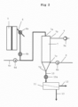
- the device according to Fig.1 has a reactor 1 for producing a polymer melt.
- the reactor 1 is also a device for melting a solid product such as used polyolefin material.
- the reactor 1 in this case can be an extruder.
- the molten polyolefin material is transferred to a granulation device 2.
- granules are produced from the molten material in a known manner.
- it can be an underwater granulator (as in Fig.1 shown).
- the granulation takes place under water.
- the resulting granulate particles are cooled simultaneously in the granulator 2.
- the cooling must not be so strong that the granulate particles are cooled below a temperature T2.
- the granulate should be cooled to a temperature which is in the range of 71°C-200°C, preferably 80°C-160°C and in the case of polyethylene particularly preferably 71°-120°C.
- the granulate is transferred via a connecting line 3 into a unit for drying the granulate (separation device) 5.
- a connecting line 3 a unit for drying the granulate (separation device) 5.
- the flow rate in the connecting line 3 can be increased by introducing a gas stream (preferably air).
- the granulate is separated from the liquid cooling medium (water) and dried.
- the separated cooling medium is fed via a pipe 4a back into a storage container (tank) 4b for the cooling medium.
- the storage container 4b has an inlet 4e for supplying cooling medium.
- the cooling medium is transferred from the storage container 4b to the granulation device 2 with the aid of a circulation device (pump) 4c.
- the cooling medium preferably passes through a heat exchanger 4d. In the heat exchanger 4d, the cooling medium can be heated or cooled as required. In particular, cooling medium returned from the separation device 5 can have too high a temperature due to contact with hot granulate and must be cooled before entering the granulation device 2.
- the fresh cooling medium which is supplied via the inlet 4e, can contain a basic medium or a pH buffer medium.
- a basic medium or a pH buffer medium can also be carried out directly into the cooling circuit, e.g. into the storage tank 4b.
- the drying of the granulate in unit 5 is carried out in addition to a mechanical separating device with the aid of gas, preferably air or a gas atmosphere comprising essentially air, at a temperature of 100 to 200°C, preferably 110 to 160°C.
- gas preferably air or a gas atmosphere comprising essentially air
- the air is led through an inlet opening 5a into the separating device 5.
- the inlet opening 5a for the gas can be located in the housing of the separating device 5 or in the connecting line 6 or in both places.
- a suction filter (not shown) can be arranged in the gas line leading to the inlet opening 5a.
- the air leaves the separating device 5 through the outlet line 5b.
- a fan 5c is arranged in the outlet line 5b to circulate the air through the separating device 5.
- the fan could alternatively also be arranged in the air inlet line 5a.
- the inlet opening 5a and the outlet line 5b could be connected to one another to form a circulatory system.
- a condenser is then to be provided in this circulatory system.
- the granulate is transferred from the separating device 5 via a connecting line 6 through an inlet opening 7a into a unit 7 with a treatment chamber.
- a start-up switch 6a with a discharge line is provided in the connecting line 6.
- the polyolefin granulate is treated according to the invention.
- the granulate particles are heat-treated by a gas stream passed through unit 7 in countercurrent or crosscurrent.
- the conditions of a fixed bed exist.
- At least 75% of the dry polyolefin granules in the treatment room of unit 7 have a temperature T3 which is in a range of T2 ⁇ 20°C, but below the melting point of the granules.
- the treatment gas introduced into the unit 7 is air.
- the treatment gas preferably has either a temperature T4 below the temperature T2 of the dry polyolefin granulate upon entering the treatment chamber, or the gas is introduced into the treatment chamber in an amount which corresponds to less than half the throughput of polyolefin granulate through the treatment chamber.
- the dry polyolefin granulate remains in the treatment chamber of unit 7 for a period of 0.5 to 20 hours, preferably 1 to 10 hours, particularly preferably 2 to 6 hours.
- the cleaned granulate leaves the unit 7 through a discharge opening 7d and a discharge line 10, preferably via a discharge device 10a, for example a shut-off unit such as a rotary valve.
- a discharge device 10a for example a shut-off unit such as a rotary valve.
- the process gas enters the unit 7 through an inlet opening 7c and leaves the unit 7 through an outlet opening 7b into a gas supply line 9.
- a blower 8a for example a Fan for circulating the gas.
- a heat exchanger 8b is provided in front of the inlet opening 7c to bring the gas to the desired temperature before it enters the unit 7.
- the process gas used in the unit 7, preferably air, can also be guided through a closed circuit system of pipes 8, 9.
- the dry polyolefin granulate in the treatment chamber of unit 7 is treated under increased pressure, preferably under an overpressure of 0.1 to 990 mbar, more preferably under an overpressure of 20 to 500 mbar.
- a further embodiment of a device suitable according to the invention is shown.
- the dried polyolefin granulate is not conveyed directly from the unit 5 into the unit 7, but is guided after the start-up switch 7 to a shut-off unit 6b such as a rotary valve.
- Heated conveying gas is supplied through a conveying gas line 6c and a device 6d for heating the conveying gas, for example a heat exchanger, in order to convey the granulate pneumatically into the unit 7 after it leaves the rotary valve 6b.
- a pump 9a preferably a vacuum pump, is arranged in the gas discharge line 9.
- the dry polyolefin granulate in the treatment chamber of the unit 7 can be treated under reduced pressure, preferably under a negative pressure of 0.1 to 999 mbar, more preferably under a negative pressure of 10 to 900 mbar, particularly preferably under a negative pressure of 20 to 500 mbar.
- the pump 9a can be used to convey the gas.
- the cleaned polyolefin granulate is in the embodiment according to Fig.2 through a separating device 11, preferably a classifying screen. Oversize particles separated in this process are removed from the product stream through a discharge line 12, while the cleaned polyolefin granulate is passed through a discharge line 13.
Landscapes
- Engineering & Computer Science (AREA)
- Mechanical Engineering (AREA)
- Chemical & Material Sciences (AREA)
- Life Sciences & Earth Sciences (AREA)
- Health & Medical Sciences (AREA)
- Sustainable Development (AREA)
- Chemical Kinetics & Catalysis (AREA)
- Medicinal Chemistry (AREA)
- Polymers & Plastics (AREA)
- Organic Chemistry (AREA)
- General Engineering & Computer Science (AREA)
- Molecular Biology (AREA)
- Microbiology (AREA)
- Processing And Handling Of Plastics And Other Materials For Molding In General (AREA)
- Separation, Recovery Or Treatment Of Waste Materials Containing Plastics (AREA)
Claims (14)
- Procédé de recyclage des polyoléfines, comprenant les étapes suivantesa) Extrusion du matériau polyoléfine usagé qui est contaminé par des composants volatils que le matériau polyoléfine a absorbés au cours de son utilisation,b) Production de granulés à partir du matériau polyoléfine sortant de l'extrusion dans un milieu de refroidissement liquide,c) Séparation du milieu de refroidissement pour obtenir un granulé sec de polyoléfined) Traitement du granulé sec de polyoléfine dans un espace de traitement avec un gaz de traitement, de préférence à contre-courant,caractérisé en ce que
le procédé est réalisé de telle sorte que les granulés secs de polyoléfine, directement après la séparation du milieu de refroidissement à l'étape c), présentent encore une température T2 supérieure à la température T1 du milieu de refroidissement liquide à l'étape b) et comprise entre 71°C et 200°C, de préférence entre 80°C et 160°C, mais inférieure au point de fusion des granulés, et qu'au moins 75 % des granulés secs de polyoléfine dans l'espace de traitement présentent une température T3 comprise entre T2 ± 20°C, mais inférieure au point de fusion des granulés. - Procédé selon la revendication 1, caractérisé en ce que le milieu de refroidissement liquide à l'étape b) est de l'eau.
- Procédé selon la revendication 1 ou 2, caractérisé en ce que l'étape c) est effectuée dans un séchoir centrifuge.
- Procédé selon l'une des revendications précédentes, caractérisé en ce que le gaz de traitement à l'étape d) est de l'air.
- Procédé selon l'une quelconque des revendications précédentes, caractérisé en ce que le gaz de traitement, lorsqu'il entre dans l'espace de traitement, soit a une température T4 inférieure à la température T2 des granulés secs de polyoléfine, soit est introduit dans l'espace de traitement en une quantité correspondant à moins de la moitié du débit des granulés de polyoléfine dans l'espace de traitement.
- Procédé selon l'une quelconque des revendications précédentes, caractérisé en ce que les granulés de polyoléfine secs restent dans l'espace de traitement pendant une période de 0,5 à 20 heures, de préférence de 1 à 10 heures, plus préférentiellement de 2 à 6 heures.
- Procédé selon l'une quelconque des revendications précédentes, caractérisé en ce que les granulés secs de polyoléfine sont traités dans l'espace de traitement sous une pression élevée, de préférence sous une surpression de 0,1 à 990 mbar, plus préférentiellement sous une surpression de 20 à 500 mbar.
- Procédé selon l'une quelconque des revendications précédentes, caractérisé en ce que les granulés secs de polyoléfine sont traités dans l'espace de traitement sous pression réduite, de préférence sous une pression réduite de 0,1 à 999 mbar, plus préférentiellement sous une pression réduite de 10 à 900 mbar, particulièrement préférentiellement sous une pression réduite de 20 à 500 mbar.
- Procédé selon l'une des revendications précédentes, caractérisé en ce que le gaz de traitement est nettoyé avec un liquide, de préférence de l'eau, après avoir quitté l'espace de traitement.
- Procédé selon l'une quelconque des revendications précédentes, caractérisé en ce que le milieu de refroidissement liquide à l'étape b) a une température T1 comprise entre 50 et 100°C, de préférence entre 70 et 100°C, plus préférentiellement entre 75 et 95°C et particulièrement préférentiellement entre 80 et 90°C.
- Procédé selon l'une quelconque des revendications précédentes, caractérisé en ce que le temps de contact entre le granulé et le milieu de refroidissement liquide est de quelques secondes, de préférence au maximum 10 s, plus préférentiellement de 0,1 à 3 s et particulièrement préférentiellement de 0,2 à 1,5 s.
- Procédé selon l'une quelconque des revendications précédentes, caractérisé en ce que pendant l'extrusion au moyen d'un dégazage de la matière fondue et/ou d'une filtration, des composants sont retirés.
- Procédé selon l'une quelconque des revendications précédentes, caractérisé en ce que le matériau polyoléfine est prétraité avant l'extrusion, le prétraitement étant choisi dans le groupe constitué par le tri par couleur, le tri par type de polymère, le broyage, le nettoyage de surface tel que le lavage, le préséchage et les combinaisons de ceuxci .
- Procédé selon l'une quelconque des revendications précédentes, caractérisé en ce que le transfert des granulés secs de polyoléfine dans l'espace de traitement est effectué par transport pneumatique.
Priority Applications (3)
| Application Number | Priority Date | Filing Date | Title |
|---|---|---|---|
| EP19163075.5A EP3708936B1 (fr) | 2019-03-15 | 2019-03-15 | Procédé de recyclage de polyoléfines |
| US16/803,227 US11286365B2 (en) | 2019-03-15 | 2020-02-27 | Process for recycling polyolefins |
| CN202010169883.4A CN111688055B (zh) | 2019-03-15 | 2020-03-12 | 用于回收聚烯烃的方法 |
Applications Claiming Priority (1)
| Application Number | Priority Date | Filing Date | Title |
|---|---|---|---|
| EP19163075.5A EP3708936B1 (fr) | 2019-03-15 | 2019-03-15 | Procédé de recyclage de polyoléfines |
Publications (2)
| Publication Number | Publication Date |
|---|---|
| EP3708936A1 EP3708936A1 (fr) | 2020-09-16 |
| EP3708936B1 true EP3708936B1 (fr) | 2024-04-17 |
Family
ID=66091843
Family Applications (1)
| Application Number | Title | Priority Date | Filing Date |
|---|---|---|---|
| EP19163075.5A Active EP3708936B1 (fr) | 2019-03-15 | 2019-03-15 | Procédé de recyclage de polyoléfines |
Country Status (3)
| Country | Link |
|---|---|
| US (1) | US11286365B2 (fr) |
| EP (1) | EP3708936B1 (fr) |
| CN (1) | CN111688055B (fr) |
Families Citing this family (2)
| Publication number | Priority date | Publication date | Assignee | Title |
|---|---|---|---|---|
| CN115479458B (zh) * | 2022-09-30 | 2024-01-26 | 湖北中烟工业有限责任公司 | 一种干燥装置 |
| CN115742080A (zh) * | 2022-11-27 | 2023-03-07 | 盐城申源塑胶有限公司 | 一种具有自动分拣装置的塑胶造粒机 |
Citations (7)
| Publication number | Priority date | Publication date | Assignee | Title |
|---|---|---|---|---|
| US20020192401A1 (en) * | 2000-01-26 | 2002-12-19 | Koji Matsumoto | Molded article from thermoplastic composite material and method for producing the same |
| JP2008000908A (ja) * | 2006-06-20 | 2008-01-10 | Npo Hiroshima Junkangata Shakai Suishin Kiko | 廃プラスチックの薄物製品へのリサイクル方法 |
| US20080185758A1 (en) * | 2004-12-20 | 2008-08-07 | Eric Damme | Pellet Treatment Unit |
| WO2011135745A1 (fr) * | 2010-04-28 | 2011-11-03 | Wpcコーポレーション株式会社 | Procédé de production de granulé composite pour moulage par extrusion, et granulé composite pour moulage par extrusion produite par le procédé |
| US20120088853A1 (en) * | 2009-07-02 | 2012-04-12 | Takeyasu Kikuchi | Molding material for extrusion foam molding, process for producing same, woody molded foam produced from the molding material, and process and apparatus for producing the woody molded foam |
| US20120214885A1 (en) * | 2009-10-27 | 2012-08-23 | Hiroyuki Tarumoto | Foamable polystyrene resin particles and process for production thereof, polystyrene resin prefoamed particles, polystyrene resin foam-molded article, heat-insulating material for building material, banking member, and vehicle interior material |
| CN107745462A (zh) * | 2017-10-16 | 2018-03-02 | 湖南旷大新材料有限公司 | 塑料回收系统及方法 |
Family Cites Families (25)
| Publication number | Priority date | Publication date | Assignee | Title |
|---|---|---|---|---|
| US5145742A (en) | 1990-08-03 | 1992-09-08 | Eastman Kodak Company | Polymer pellet configuration for solid-state polymerization |
| DE19536289C2 (de) | 1995-09-29 | 1999-01-07 | Krupp Werner & Pfleiderer Gmbh | Verfahren zur Durchführung von kontinuierlichen Aufbereitungsprozessen mit gleichsinnig drehenden, dicht kämmenden Doppelschneckenextrudern |
| US5767230A (en) | 1995-11-02 | 1998-06-16 | Ecoplast Corporation | Process for removing volatiles from post-consumer recycled polyolefin chips |
| JP2001038729A (ja) * | 1999-07-29 | 2001-02-13 | Hitachi Ltd | 家庭電化製品及びoa機器製品の再製品化システム |
| US6426026B1 (en) * | 1999-12-28 | 2002-07-30 | Union Carbide Chemicals & Plastics Technology Corporation | Process for pelletizing ultra-high melt flow polymers |
| DE10145019A1 (de) | 2001-09-13 | 2003-04-03 | Bayer Cropscience Gmbh | Kombinationen aus Herbiziden und Safenern |
| JP2005199531A (ja) * | 2004-01-14 | 2005-07-28 | Kankyo Keiei Sogo Kenkyusho:Kk | ペレット及びその製造方法並びにその成形品 |
| EP1591457A1 (fr) * | 2004-04-30 | 2005-11-02 | SOLVAY (Société Anonyme) | Traitement de polyolefine permettant de separer des matieres volatiles |
| DE102005026354A1 (de) * | 2005-06-01 | 2006-12-07 | Bkg Bruckmann & Kreyenborg Granuliertechnik Gmbh | Verfahren zur thermischen Behandlung von Polyesterpellets, um eine Teilkristallisation zu erreichen |
| US7875184B2 (en) * | 2005-09-22 | 2011-01-25 | Eastman Chemical Company | Crystallized pellet/liquid separator |
| US7638596B2 (en) * | 2006-05-24 | 2009-12-29 | Eastman Chemical Company | Crystallizer temperature control via jacketing/insulation |
| DE102007040135A1 (de) | 2007-08-24 | 2009-02-26 | Bkg Bruckmann & Kreyenborg Granuliertechnik Gmbh | Verfahren zur Herstellung von Polyester-Granulaten aus hochviskosen Polyester-Schmelzen sowie Vorrichtung zur Herstellung der Polyester-Granulate |
| EP2195349B1 (fr) * | 2007-09-13 | 2012-07-11 | ExxonMobil Research and Engineering Company | Procede de production en ligne de polymeres plastifies et melanges de polymeres plastifies |
| ES2367926T3 (es) | 2007-12-18 | 2011-11-10 | Borealis Technology Oy | Eliminación de compuestos volátiles de gránulos de polímeros. |
| US8351027B2 (en) | 2009-06-15 | 2013-01-08 | Panduit Corp. | Method and metric for selecting and designing multimode fiber for improved performance |
| ES2624830T5 (es) | 2009-12-03 | 2021-11-17 | Altium Packaging Lp | Procedimiento de producción de pellas de PCR |
| WO2011087729A2 (fr) * | 2010-01-14 | 2011-07-21 | Exxonmobil Chemical Patents Inc. | Procédés et appareils de finissage et de conditionnement de polymères |
| EP2433771B1 (fr) * | 2010-09-28 | 2016-12-21 | Uhde Inventa-Fischer GmbH | Procédé d'augmentation du poids moléculaire en utilisant la chaleur résiduelle de granulés de polyester |
| EP2780141B1 (fr) | 2011-11-14 | 2015-09-16 | Borealis AG | Élimination de composés volatiles de granules de polymère par distillation de vapeur |
| US10745517B2 (en) * | 2012-09-26 | 2020-08-18 | Polymetrix Ag | Process and apparatus for direct crystallization of polycondensates |
| EP2712881B1 (fr) * | 2012-09-26 | 2015-05-20 | Bühler Thermal Processes AG | Procédé et dispositif de cristallisation directe de polymères sous gaz inerte |
| CN104859066A (zh) * | 2014-02-24 | 2015-08-26 | 许黎明 | 木塑复合材料专用聚烯烃塑料纤细化原料生产机组 |
| CN107530671B (zh) * | 2015-03-24 | 2020-10-16 | Sabic环球技术有限责任公司 | 连续气体流化床聚合方法 |
| EP4257629A3 (fr) * | 2017-02-17 | 2024-01-10 | Polymetrix AG | Procédé et dispositif de cristallisation directe de polycondensats |
| EP3442763B1 (fr) * | 2017-06-26 | 2019-06-26 | Basell Polyolefine GmbH | Procédé de séchage et de dégazage de pastilles |
-
2019
- 2019-03-15 EP EP19163075.5A patent/EP3708936B1/fr active Active
-
2020
- 2020-02-27 US US16/803,227 patent/US11286365B2/en active Active
- 2020-03-12 CN CN202010169883.4A patent/CN111688055B/zh active Active
Patent Citations (7)
| Publication number | Priority date | Publication date | Assignee | Title |
|---|---|---|---|---|
| US20020192401A1 (en) * | 2000-01-26 | 2002-12-19 | Koji Matsumoto | Molded article from thermoplastic composite material and method for producing the same |
| US20080185758A1 (en) * | 2004-12-20 | 2008-08-07 | Eric Damme | Pellet Treatment Unit |
| JP2008000908A (ja) * | 2006-06-20 | 2008-01-10 | Npo Hiroshima Junkangata Shakai Suishin Kiko | 廃プラスチックの薄物製品へのリサイクル方法 |
| US20120088853A1 (en) * | 2009-07-02 | 2012-04-12 | Takeyasu Kikuchi | Molding material for extrusion foam molding, process for producing same, woody molded foam produced from the molding material, and process and apparatus for producing the woody molded foam |
| US20120214885A1 (en) * | 2009-10-27 | 2012-08-23 | Hiroyuki Tarumoto | Foamable polystyrene resin particles and process for production thereof, polystyrene resin prefoamed particles, polystyrene resin foam-molded article, heat-insulating material for building material, banking member, and vehicle interior material |
| WO2011135745A1 (fr) * | 2010-04-28 | 2011-11-03 | Wpcコーポレーション株式会社 | Procédé de production de granulé composite pour moulage par extrusion, et granulé composite pour moulage par extrusion produite par le procédé |
| CN107745462A (zh) * | 2017-10-16 | 2018-03-02 | 湖南旷大新材料有限公司 | 塑料回收系统及方法 |
Also Published As
| Publication number | Publication date |
|---|---|
| US20200291200A1 (en) | 2020-09-17 |
| CN111688055B (zh) | 2024-03-22 |
| US11286365B2 (en) | 2022-03-29 |
| CN111688055A (zh) | 2020-09-22 |
| EP3708936A1 (fr) | 2020-09-16 |
Similar Documents
| Publication | Publication Date | Title |
|---|---|---|
| EP2176046B1 (fr) | Procédé et dispositif de traitement de matériau synthétique | |
| EP2180987B2 (fr) | Procédé de production de granulés de polyester faiblement hydrolysés à partir de polyester fondu hautement visqueux, et procédé de production de granulés de polyester | |
| EP2525953B1 (fr) | Procédé et dispositif pour le traitement et la décontamination | |
| DE102006027176B4 (de) | Verfahren und Vorrichtung zur Verringerung des Acetaldehydgehaltes von Polyestergranulat sowie Polyestergranulat | |
| DE60018467T2 (de) | Behandlung von polymerschaum | |
| DE102006023354B4 (de) | Verfahren und Vorrichtung zur Wiederverwertung von Polyestermaterial | |
| DE19914116C2 (de) | Unterwasser-Granulator und Verfahren zur Granulierung thermoplastischer Kunststoffe | |
| EP1676686A2 (fr) | Procédé et dispositif pour augmenter la viscosité limite de polyester | |
| EP2029267B1 (fr) | Procédé et dispositif de polymérisation en continu d'un polymère en phase solide | |
| DE1905677A1 (de) | Verfahren zum Kristallisieren von Polyestern | |
| EP3708936B1 (fr) | Procédé de recyclage de polyoléfines | |
| CH711770B1 (de) | Verfahren zur Herstellung eines nicht klebenden Granulats aus einem Polyestermaterial und zur Weiterverarbeitung eines so hergestellten Granulats. | |
| EP2958722B1 (fr) | Installation de transformation de matière en fusion | |
| DE10144747A1 (de) | Kontinuierliche thermische Behandlung von Schüttgütern | |
| EP2886984A2 (fr) | Procédé de séchage et/ou de cristallisation de produits en vrac et installation d'exécution d'un tel procédé | |
| EP3363609B1 (fr) | Dispositif et procédé de traitement d'une matière plastique fondue | |
| EP3377288B1 (fr) | Procédé de production de granulés de matière plastique | |
| EP3650186B1 (fr) | Procédé et dispositif de cristallisation directe de polycondensats | |
| AT508655B1 (de) | Verfahren zur aufbereitung und entgiftung | |
| DE2745179C2 (de) | Vorrichtung zum chargenweisen Mischen, Trocknen und/oder Granulieren rieselfähiger Schüttgüter mit breitem Partikelspektrum | |
| EP0850743B1 (fr) | Procédé de conditionnement et traitement de matières plastiques, en particulier de polyvinylbutyral, et manufacture du produit recyclé | |
| DE19757624B4 (de) | Verfahren zur Kühlung von Granulat | |
| WO1994014527A1 (fr) | Procede et dispositif de preparation de granules comprimes a surface collante | |
| AT509389B1 (de) | Verfahren zur aufbereitung und entgiftung | |
| WO2023017038A1 (fr) | Méthode de production d'un granulé de plastique et utilisation du granulé |
Legal Events
| Date | Code | Title | Description |
|---|---|---|---|
| PUAI | Public reference made under article 153(3) epc to a published international application that has entered the european phase |
Free format text: ORIGINAL CODE: 0009012 |
|
| STAA | Information on the status of an ep patent application or granted ep patent |
Free format text: STATUS: THE APPLICATION HAS BEEN PUBLISHED |
|
| AK | Designated contracting states |
Kind code of ref document: A1 Designated state(s): AL AT BE BG CH CY CZ DE DK EE ES FI FR GB GR HR HU IE IS IT LI LT LU LV MC MK MT NL NO PL PT RO RS SE SI SK SM TR |
|
| AX | Request for extension of the european patent |
Extension state: BA ME |
|
| STAA | Information on the status of an ep patent application or granted ep patent |
Free format text: STATUS: REQUEST FOR EXAMINATION WAS MADE |
|
| 17P | Request for examination filed |
Effective date: 20210316 |
|
| RBV | Designated contracting states (corrected) |
Designated state(s): AL AT BE BG CH CY CZ DE DK EE ES FI FR GB GR HR HU IE IS IT LI LT LU LV MC MK MT NL NO PL PT RO RS SE SI SK SM TR |
|
| STAA | Information on the status of an ep patent application or granted ep patent |
Free format text: STATUS: EXAMINATION IS IN PROGRESS |
|
| 17Q | First examination report despatched |
Effective date: 20220523 |
|
| GRAP | Despatch of communication of intention to grant a patent |
Free format text: ORIGINAL CODE: EPIDOSNIGR1 |
|
| STAA | Information on the status of an ep patent application or granted ep patent |
Free format text: STATUS: GRANT OF PATENT IS INTENDED |
|
| INTG | Intention to grant announced |
Effective date: 20231220 |
|
| GRAS | Grant fee paid |
Free format text: ORIGINAL CODE: EPIDOSNIGR3 |
|
| GRAA | (expected) grant |
Free format text: ORIGINAL CODE: 0009210 |
|
| STAA | Information on the status of an ep patent application or granted ep patent |
Free format text: STATUS: THE PATENT HAS BEEN GRANTED |
|
| AK | Designated contracting states |
Kind code of ref document: B1 Designated state(s): AL AT BE BG CH CY CZ DE DK EE ES FI FR GB GR HR HU IE IS IT LI LT LU LV MC MK MT NL NO PL PT RO RS SE SI SK SM TR |
|
| REG | Reference to a national code |
Ref country code: GB Ref legal event code: FG4D Free format text: NOT ENGLISH |