EP2886880A2 - Möbel - Google Patents
Möbel Download PDFInfo
- Publication number
- EP2886880A2 EP2886880A2 EP14004245.8A EP14004245A EP2886880A2 EP 2886880 A2 EP2886880 A2 EP 2886880A2 EP 14004245 A EP14004245 A EP 14004245A EP 2886880 A2 EP2886880 A2 EP 2886880A2
- Authority
- EP
- European Patent Office
- Prior art keywords
- furniture
- component
- retaining projection
- furniture according
- plastic
- Prior art date
- Legal status (The legal status is an assumption and is not a legal conclusion. Google has not performed a legal analysis and makes no representation as to the accuracy of the status listed.)
- Granted
Links
Images

Classifications
-
- F—MECHANICAL ENGINEERING; LIGHTING; HEATING; WEAPONS; BLASTING
- F16—ENGINEERING ELEMENTS AND UNITS; GENERAL MEASURES FOR PRODUCING AND MAINTAINING EFFECTIVE FUNCTIONING OF MACHINES OR INSTALLATIONS; THERMAL INSULATION IN GENERAL
- F16B—DEVICES FOR FASTENING OR SECURING CONSTRUCTIONAL ELEMENTS OR MACHINE PARTS TOGETHER, e.g. NAILS, BOLTS, CIRCLIPS, CLAMPS, CLIPS OR WEDGES; JOINTS OR JOINTING
- F16B12/00—Jointing of furniture or the like, e.g. hidden from exterior
- F16B12/04—Non-loosenable joints for non-metal furniture parts, e.g. glued
-
- A—HUMAN NECESSITIES
- A47—FURNITURE; DOMESTIC ARTICLES OR APPLIANCES; COFFEE MILLS; SPICE MILLS; SUCTION CLEANERS IN GENERAL
- A47B—TABLES; DESKS; OFFICE FURNITURE; CABINETS; DRAWERS; GENERAL DETAILS OF FURNITURE
- A47B88/00—Drawers for tables, cabinets or like furniture; Guides for drawers
- A47B88/40—Sliding drawers; Slides or guides therefor
- A47B88/423—Fastening devices for slides or guides
-
- A—HUMAN NECESSITIES
- A47—FURNITURE; DOMESTIC ARTICLES OR APPLIANCES; COFFEE MILLS; SPICE MILLS; SUCTION CLEANERS IN GENERAL
- A47B—TABLES; DESKS; OFFICE FURNITURE; CABINETS; DRAWERS; GENERAL DETAILS OF FURNITURE
- A47B88/00—Drawers for tables, cabinets or like furniture; Guides for drawers
- A47B88/40—Sliding drawers; Slides or guides therefor
- A47B88/453—Actuated drawers
- A47B88/46—Actuated drawers operated by mechanically-stored energy, e.g. by springs
- A47B88/463—Actuated drawers operated by mechanically-stored energy, e.g. by springs self-opening
-
- A—HUMAN NECESSITIES
- A47—FURNITURE; DOMESTIC ARTICLES OR APPLIANCES; COFFEE MILLS; SPICE MILLS; SUCTION CLEANERS IN GENERAL
- A47B—TABLES; DESKS; OFFICE FURNITURE; CABINETS; DRAWERS; GENERAL DETAILS OF FURNITURE
- A47B88/00—Drawers for tables, cabinets or like furniture; Guides for drawers
- A47B88/40—Sliding drawers; Slides or guides therefor
- A47B88/453—Actuated drawers
- A47B88/46—Actuated drawers operated by mechanically-stored energy, e.g. by springs
- A47B88/467—Actuated drawers operated by mechanically-stored energy, e.g. by springs self-closing
Definitions
- the invention relates to a piece of furniture, with at least one metal component and at least one plastic component, which are fastened to each other.
- Hybrid components In many industrial sectors, for example in the automotive industry, the demand for lightweight construction and economy leads to the development of hybrid components in which two or more materials are combined. Hybrid components have properties that a single material typically can not provide.
- the object of the invention is to provide a piece of furniture of the type mentioned, which can be produced in a simple and cost-effective manner Way is constructed of a composite of metal and plastic components.
- the furniture according to the invention is characterized in that the metal component has at least one holding projection, which is pressed into the material of the plastic component for attachment to the plastic component to form a holding recess receiving the retaining projection.
- the plastic furniture component and the metal furniture component are thus produced separately from each other and then connected to each other.
- the separate production of the respective furniture components results in a significantly higher design freedom compared to the production of the composite by means of in-mold assembly.
- the injection mold can be designed relatively simple in the rule.
- the cycle time for producing a hybrid component, ie a plastic-metal hybrid structure is shorter than in in-mold assembly, if the assembly process for connecting the individual furniture components requires less time than the injection molding of the plastic part.
- the distortion caused by the processing shrinkage of the plastic during in-mold assembly does not occur.
- the furniture according to the invention is thus a hybrid structure of metal furniture components and plastic furniture components, which is produced in a simple manner and inexpensively.
- the retaining projection is designed as a particular cylindrical retaining collar.
- the metal component is designed as a longitudinally extending, in particular elongate connecting element, which has a retaining projection equipped with the holding portion and a base portion connected to the holding portion, which is coupled or coupled with another furniture component.
- the connecting element may be formed, for example, in the manner of a connecting bolt.
- the holding portion of the connecting element has a bearing surface equipped with a bearing surface, which is held in contact with the associated plastic component, on the one hand, the base portion in particular integrally attached and on the other hand in particular integrally formed the retaining projection.
- the retaining projection is formed as a hollow cylindrical retaining collar, which has at least one circumferential radially inwardly and / or radially outwardly oriented in the manner of a barb-trained retaining web for securing against pulling on the inner and / or outer periphery.
- a tapered collar wall is formed with an insertion bevel at the free end.
- At least one movable furniture part guided in the furniture body of the furniture via a guide device is provided, wherein the guide device comprises at least one guide unit of at least one Running rail and a fastened to the furniture body carcass rail, wherein the metal component of the running rail and / or carcass rail is formed and wherein in particular the retaining projection is formed out of the material of the running rail and / or carcass rail.
- the at least one plastic component is a feed and / or pull-out unit, in particular having a plastic housing, and / or a slide bearing, wherein preferably the feed unit and / or pull-out unit is fastened to the carcass rail.
- the metal component is a mounting plate, which is for example mounted on the bottom of a drawer compartment. The plastic component may then be a feed unit or pull-out unit, which is pressed onto the mounting plate equipped with the holding projection.
- the plastic component is a damper housing of a damper.
- the metal component is formed by a flap fitting for controlling movement of a movable furniture part in the form of a flap, wherein preferably the retaining projection is formed out of the material of the fitting.
- the metal components are a hinge cup and / or arm, wherein preferably the retaining projection is formed from the material of the hinge cup and / or arm.
- the Figures 1 and 2 show a first embodiment of the furniture 11 according to the invention.
- the furniture 11 has a furniture body and a movably mounted thereto movable furniture part (not shown).
- the movable furniture part may for example be designed as a drawer.
- a metal component 12 is connected to a plastic component 13 to form a plastic-metal hybrid structure.
- the plastic component is a plastic side panel of a drawer and the metal component 12 about an elongated connecting element in the form of a connecting bolt.
- the metal component 12 has at least one holding projection 14, which is pressed into the material of the plastic component 13 for attachment to the plastic component 13 to form a holding recess 15 receiving the holding projection 14.
- the retaining projection 14 is thus on the connecting bolt.
- the connecting bolt has a holding portion 16, on which the holding projection 14 is arranged and a base portion 17, in particular integrally connected to the holding portion 16.
- a base portion 17 of the connecting bolt another furniture component is coupled or coupled, for example, an internal divider (not shown) for dividing the drawer into individual subjects.
- the retaining projection 14 is formed as a hollow cylindrical retaining collar, which has a circumferential radially outwardly directed, annular retaining web 18 according to the embodiment shown on the outer circumference, which is designed in the manner of a barb and serves to secure the connecting bolt against pulling.
- the holding section has a bearing surface 19 equipped with a conditioning section 20, which is formed in the example of a rotating at the transition between retaining projection and base portion 17 on the outer circumference annular abutment shoulder.
- the retaining collar has a tapered to its free end collar wall with insertion bevel 21, whereby the connecting bolt easily in the plastic material of the plastic component 13, so in the example, the side part can be pressed.
- the insertion bevel 21 is formed by a conically widening inner portion 22 which connects in the axial direction along a longitudinal axis 23 of the connecting bolt to the cylindrical interior 24 of the retaining projection 14.
- the base portion 17 has a in the direction of the holding portion 16 conically widening support portion 25, whose frontal end forms the aforementioned abutment shoulder.
- the holding section 16 facing away from the base portion 17 is formed pin-shaped cylindrical.
- the connecting bolt is first attached to the plastic side panel. Thereafter, the connecting bolt is pressed with a press-in force in the material of the side part, wherein in the material of the side part, a retaining projection receiving retaining recess 15 is formed.
- the annular abutment shoulder specifies the press-in depth, ie, if the stop shoulder strikes against the side wall of the side part, the retaining projection 14 is completely pressed in. The press-fitting process is facilitated by the aforementioned insertion bevel 21.
- the annular retaining web 18 on the outer circumference of the retaining projection 14 prevents unintentional withdrawal or release of the connecting bolt from the side part.
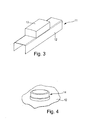
- FIGS. 3 and 4 show a second embodiment of the furniture 11 according to the invention in this embodiment the metal component is formed by a running rail, which is part of a guide device for guiding a movable furniture part, such as drawer, in the furniture.
- the plastic component 13 is a plain bearing having a plastic housing.
- the holding projection 14 is produced by first providing the running rail with a bore, which is then pressed outwards by means of a punch at this point, so that a collar is formed.
- the slide bearing made of plastic material is then pressed onto the retaining projection 14 by means of pressing force, whereby a plastic-metal hybrid composite is formed.
Landscapes
- Engineering & Computer Science (AREA)
- General Engineering & Computer Science (AREA)
- Mechanical Engineering (AREA)
- Drawers Of Furniture (AREA)
- Connection Of Plates (AREA)
Abstract
Description
- Die Erfindung betrifft ein Möbel, mit wenigstens einer Metallkomponente und wenigstens einer Kunststoffkomponente, die aneinander befestigt sind.
- In vielen Industriebranchen, beispielsweise in der Automobilindustrie, führt die Forderung nach Leichtbau und Wirtschaftlichkeit zur Entwicklung von Hybridbauteilen, bei denen zwei oder mehrere Werkstoffe kombiniert sind. Hybridbauteile haben Eigenschaften, die ein einzelner Werkstoff in der Regel nicht bieten kann.
- Bei Kunststoff-Metall-Hybridstrukturen ist es bekannt, die Verbindung zwischen Kunststoff und Metall durch Anspritzen des Kunststoffs an das Metallblech im Spritzgießprozess (In-Mould Assembly, IMA) herzustellen.
- Allerdings ist die Gestaltungsfreiheit bei der Herstellung solcher Kunststoff-Metall-Hybridbauteile begrenzt, da der Kunststoff an die Gestalt des zuvor gefertigten Metallteils anzupassen ist. Ferner ist auch das Spritzgießwerkzeug relativ aufwendig zu fertigen, was Kostenachteile mit sich bringt.
- Aufgabe der Erfindung ist es, ein Möbel der eingangs erwähnten Art zu schaffen, das in einfacher und kostengünstig herzustellenden Weise aus einem Verbund von Metall- und Kunststoffkomponenten aufgebaut ist.
- Diese Aufgabe wird durch ein Möbel mit den Merkmalen des unabhängigen Anspruchs 1 gelöst. Weiterbildungen der Erfindung sind in den Unteransprüchen dargestellt.
- Das erfindungsgemäße Möbel zeichnet sich dadurch aus, dass die Metallkomponente wenigstens einen Haltevorsprung aufweist, der zur Befestigung an der Kunststoffkomponente unter Bildung einer den Haltevorsprung aufnehmenden Haltevertiefung in das Material der Kunststoffkomponente eingepresst ist.
- Die Kunststoff-Möbelkomponente und die Metall-Möbelkomponente werden also getrennt voneinander hergestellt und danach miteinander verbunden. Durch die getrennte Herstellung der jeweiligen Möbelkomponenten ergibt sich eine deutlich höhere Gestaltungsfreiheit im Vergleich zur Herstellung des Verbundes mittels In-Mould Assembly. Bei der Herstellung der Kunststoff-Möbelkomponente kann das Spritzgießwerkzeug in der Regel relativ einfach gestaltet sein. Die Zykluszeit zur Herstellung eines Hybridbauteils, also einer Kunststoff-Metall-Hybridstruktur ist kürzer als beim In-Mould Assembly, wenn der Montagevorgang zur Verbindung der einzelnen Möbelkomponenten weniger Zeit als das Spritzgießen des Kunststoffteils erfordert. Ferner tritt der durch die Verarbeitungsschwindung des Kunststoffs beim In-Mould Assembly verursachte Verzug nicht auf. Das erfindungsgemäße Möbel ist also eine Hybridstruktur aus Metall-Möbelkomponenten und Kunststoff-Möbelkomponenten, die in einfacher Weise und kostengünstig hergestellt ist.
- Bei einer Weiterbildung der Erfindung ist der Haltevorsprung als insbesondere zylindrischer Haltekragen ausgebildet.
- In besonders bevorzugter Weise ist die Metallkomponente als sich entlang einer Längsachse erstreckendes, insbesondere längliches Verbindungselement ausgebildet, das einen mit dem Haltevorsprung ausgestatteten Halteabschnitt und einen mit dem Halteabschnitt verbundenen Basisabschnitt aufweist, der mit einer weiteren Möbelkomponente koppelbar oder gekoppelt ist.
- Das Verbindungselement kann beispielsweise nach Art eines Verbindungsbolzens ausgebildet sein.
- Zweckmäßigerweise weist der Halteabschnitt des Verbindungselementes eine mit einer Anlagefläche ausgestattete Anlagepartie auf, die in Anlage an die zugeordnete Kunststoffkomponente gehalten ist, an die einerseits der Basisabschnitt insbesondere einstückig angesetzt und andererseits insbesondere einstückig der Haltevorsprung angeformt ist.
- In besonders bevorzugter Weise ist der Haltevorsprung als hohlzylindrischer Haltekragen ausgebildet, der am Innen- und/oder Außenumfang wenigstens einen umlaufenden nach radial innen und/oder nach radial außen ausgerichteten nach Art eines Widerhakens ausgebildeten vorzugsweise ringförmigen Haltesteg zur Sicherung gegen Herausziehen besitzt.
- Um das Verbindungselement in einfacher Weise in die Kunststoffkomponente einpressen zu können, ist an dessen freiem Ende eine spitz zulaufende Kragenwand mit einer Einführschräge ausgebildet.
- Bei einer Weiterbildung der Erfindung ist wenigstens ein im Möbelkorpus des Möbels über eine Führungseinrichtung geführtes bewegbares Möbelteil vorgesehen, wobei die Führungseinrichtung wenigstens eine Führungseinheit aus wenigstens einer Laufschiene und einer am Möbelkorpus befestigbaren Korpusschiene aufweist, wobei die Metallkomponente von der Laufschiene und/oder Korpusschiene gebildet ist und wobei insbesondere der Haltevorsprung aus dem Material der Laufschiene und/oder Korpusschiene herausgeformt ist.
- Bei einer Weiterbildung der Erfindung handelt es sich bei der wenigstens einen Kunststoffkomponente um eine insbesondere ein Kunststoffgehäuse aufweisende Einzugs- und/oder Auszugseinheit und/oder um ein Gleitlager, wobei vorzugsweise die Einzugseinheit und/oder Auszugseinheit an der Korpusschiene befestigt ist. Alternativ ist es möglich, dass die Metallkomponente eine Montageplatte ist, die beispielsweise am Boden eines Schubladenfachs montierbar ist. Bei der Kunststoffkomponente kann es sich dann um eine Einzugseinheit oder Auszugseinheit handeln, die auf die mit dem Haltevorsprung ausgestattete Montageplatte gepresst ist.
- Es ist möglich, dass es sich bei der Kunststoffkomponente um ein Dämpfergehäuse eines Dämpfers handelt.
- Bei einer Weiterbildung der Erfindung ist die Metallkomponente von einem Klappenbeschlag zur Bewegungssteuerung eines bewegbaren Möbelteils in Form einer Klappe gebildet, wobei vorzugsweise der Haltevorsprung aus dem Material des Beschlags herausgeformt ist.
- Ferner ist es möglich, dass es sich bei den Metallkomponenten um einen Scharniertopf und/oder -arm handelt, wobei vorzugsweise der Haltevorsprung aus dem Material des Scharniertopfes und/oder -arms geformt ist.
- Bevorzugte Ausführungsbeispiele der Erfindung sind in der Zeichnung dargestellt und werden im Folgenden näher erläutert. In der Zeichnung zeigen:
- Figur 1
- eine schematische Darstellung eines ersten Ausführungsbeispiels des erfindungsgemäßen Möbels vor dem Verbinden einer Metall-Möbelkomponente mit einer Kunststoff-Möbelkomponente,
- Figur 2
- das Möbel von
Figur 1 , wobei eine Kunststoff-Metall-Hybridstruktur aus Metall-Möbelkomponente und Kunstsoff-Möbelkomponente gebildet ist, - Figur 3
- eine schematische perspektivische Ansicht auf ein zweites Ausführungsbeispiel eines erfindungsgemäßen Möbels, bei dem die Metall-Möbelkomponente von einer Laufschiene und die Kunststoff-Möbelkomponente von einem Gleitlager gebildet sind und
- Figur 4
- eine schematische perspektivische Darstellung der Metall-Möbelkomponente von
Figur 3 mit daran ausgebildeten Haltevorsprung. - Die
Figuren 1 und 2 zeigen ein erstes Ausführungsbeispiel des erfindungsgemäßen Möbels 11. Das Möbel 11 besitzt einen Möbelkorpus und ein daran beweglich gelagertes bewegbares Möbelteil (nicht dargestellt). Das bewegbare Möbelteil kann beispielsweise als Schublade ausgestaltet sein. - Im vorliegenden Fall wird eine Metallkomponente 12 mit einer Kunststoffkomponente 13 zu einer Kunststoff-Metall-Hybridstruktur verbunden. Im Beispielsfall handelt es sich bei der Kunststoffkomponente um ein aus Kunststoff bestehendes Seitenteil einer Schublade und bei der Metallkomponente 12 um ein längliches Verbindungselement in Form eines Verbindungsbolzens.
- Die Metallkomponente 12 weist wenigstens einen Haltevorsprung 14 auf, der zur Befestigung an der Kunststoffkomponente 13 unter Bildung einer den Haltevorsprung 14 aufnehmenden Haltevertiefung 15 in das Material der Kunststoffkomponente 13 eingepresst ist.
- Im vorliegend, gezeigten Beispielsfall befindet sich der Haltevorsprung 14 also am Verbindungsbolzen.
- Der Verbindungsbolzen besitzt einen Halteabschnitt 16, an dem der Haltevorsprung 14 angeordnet ist und einen mit dem Halteabschnitt 16 insbesondere einstückig verbundenen Basisabschnitt 17. Am Basisabschnitt 17 des Verbindungsbolzens ist eine weitere Möbelkomponente angekoppelt oder ankoppelbar, beispielsweise ein Innenteiler (nicht dargestellt) zur Unterteilung der Schublade in einzelne Fächer.
- Der Haltevorsprung 14 ist als hohlzylindrischer Haltekragen ausgebildet, der gemäß dem gezeigten Ausführungsbeispiel am Außenumfang einen umlaufenden nach radial außen ausgerichteten, ringförmigen Haltesteg 18 aufweist, der nach Art eines Widerhakens ausgebildet ist und zur Sicherung des Verbindungsbolzens gegen Herausziehen dient.
- Ferner besitzt der Halteabschnitt eine mit einer Anlagefläche 19 ausgestattete Anlagepartie 20, die im Beispielsfall von einer am Übergang zwischen Haltevorsprung und Basisabschnitt 17 am Außenumfang umlaufenden ringförmigen Anlageschulter gebildet ist.
- Der Haltekragen besitzt eine zu dessen freiem Ende spitz zulaufende Kragenwand mit Einführschräge 21, womit sich der Verbindungsbolzen leicht in das Kunststoffmaterial der Kunststoffkomponente 13, also im Beispielsfall das Seitenteil, einpressen lässt. Die Einführschräge 21 wird durch einen sich konisch erweiternden Innenabschnitt 22 gebildet, der in Axialrichtung längs einer Längsachse 23 des Verbindungsbolzens an den zylindrischen Innenraum 24 des Haltevorsprungs 14 anschließt.
- Im Beispielsfall besitzt der Basisabschnitt 17 einen sich in Richtung des Halteabschnitts 16 konisch erweiternden Stützabschnitt 25, dessen stirnseitiges Ende die bereits erwähnte Anlageschulter bildet.
- Der dem Halteabschnitt 16 abgewandte Teil des Basisabschnitts 17 ist stiftförmig zylindrisch ausgebildet.
- Wie die Zusammenschau der
Figuren 1 und 2 zeigt, wird der Verbindungsbolzen zunächst an das Kunststoff-Seitenteil angesetzt. Danach wird der Verbindungsbolzen mit einer Einpresskraft in das Material des Seitenteils eingepresst, wobei im Material des Seitenteils eine den Haltevorsprung aufnehmende Haltevertiefung 15 gebildet wird. Die ringförmige Anlageschulter gibt die Einpresstiefe vor, d.h. schlägt die Anschlagschulter an die Seitenwand des Seitenteils an, ist der Haltevorsprung 14 vollständig eingepresst. Der Einpressvorgang wird durch die bereits erwähnte Einführschräge 21 erleichtert. Der ringförmige Haltesteg 18 am Außenumfang des Haltevorsprungs 14 verhindert ein unbeabsichtigtes Herausziehen bzw. Lösen des Verbindungsbolzens vom Seitenteil. - Die
Figuren 3 und 4 zeigen ein zweites Ausführungsbeispiel des erfindungsgemäßen Möbels 11. Bei diesem Ausführungsbeispiel wird die Metallkomponente von einer Laufschiene gebildet, die Bestandteil einer Führungseinrichtung zur Führung eines bewegbaren Möbelteils, beispielsweise Schublade, im Möbel ist. Bei der Kunststoffkomponente 13 handelt es sich um ein ein Kunststoffgehäuse aufweisendes Gleitlager. - Wie insbesondere in
Figur 4 gezeigt, ist an der Laufschiene ein nach außen abstehender Haltevorsprung 14 ausgebildet. Der Haltevorsprung 14 wird dadurch hergestellt, dass zunächst die Laufschiene mit einer Bohrung versehen wird, die dann mittels eines Stempels an dieser Stelle nach außen gedrückt wird, so dass ein Kragen entsteht. Das aus Kunststoffmaterial bestehende Gleitlager wird dann auf den Haltevorsprung 14 mittels Presskraft aufgepresst, wodurch ein Kunststoff-Metall-Hybridverbund entsteht.
Claims (12)
- Möbel, mit wenigstens einer Metallkomponente (12) und wenigstens einer Kunststoffkomponente (13), die aneinander befestigt sind, dadurch gekennzeichnet, dass die Metallkomponente (12) wenigstens einen Haltevorsprung (14) aufweist, der zur Befestigung an der Kunststoffkomponente (13) unter Bildung einer den Haltevorsprung (14) aufnehmenden Haltevertiefung (15) in das Material der Kunststoffkomponente (13) eingepresst ist.
- Möbel nach Anspruch 1, dadurch gekennzeichnet, dass der Haltevorsprung (14) als insbesondere zylindrischer Haltekragen ausgebildet ist.
- Möbel nach Anspruch 1 oder 2, dadurch gekennzeichnet, dass die Metallkomponente (12) als sich entlang einer Längsachse (23) erstreckendes insbesondere längliches Verbindungselement ausgebildet ist, das einen mit dem Haltevorsprung (14) ausgestatteten Halteabschnitt (16) und einen mit dem Halteabschnitt (16) verbundenen Basisabschnitt (17) aufweist, der mit einer weiteren Möbelkomponente koppelbar oder gekoppelt ist.
- Möbel nach Anspruch 3, dadurch gekennzeichnet, dass das Verbindungselement nach Art eines Verbindungsbolzens ausgebildet ist.
- Möbel nach Anspruch 3 oder 4, dadurch gekennzeichnet, dass der Halteabschnitt (16) des Verbindungselementes eine mit einer Anlagefläche (19) ausgestattete Anlagepartie (20) aufweist, die in Anlage an die zugeordnete Kunststoffkomponente (13) gehalten ist, an die einerseits der Basisabschnitt (17) insbesondere einstückig angesetzt und andererseits insbesondere einstückig der Haltevorsprung (14) angeformt ist.
- Möbel nach Anspruch 5, dadurch gekennzeichnet, dass der Haltevorsprung (14) als hohlzylindrischer Haltekragen ausgebildet ist, der am Innen- und/oder Außenumfang wenigstens einen umlaufenden nach radial innen und/oder nach radial außen ausgerichteten nach Art eines Widerhakens ausgebildeten Haltesteg (18) zur Sicherung gegen Herausziehen besitzt.
- Möbel nach Anspruch 6, dadurch gekennzeichnet, dass der Haltekragen eine zu dessen freiem Ende spitz zulaufende Kragenwand mit einer Einführschräge (21) aufweist.
- Möbel nach Anspruch 1 oder 2, gekennzeichnet durch wenigstens ein im Möbelkorpus des Möbels über eine Führungseinrichtung geführtes bewegbares Möbelteil, wobei die Führungseinrichtung wenigstens eine Führungseinheit aus wenigstens einer Laufschiene und einer am Möbelkorpus befestigbaren Korpusschiene aufweist, wobei die Metallkomponente (12) von der Laufschiene und/oder Korpusschiene gebildet ist und wobei insbesondere der Haltevorsprung (14) aus dem Material der Laufschiene und/oder Korpusschiene herausgeformt ist.
- Möbel nach Anspruch 8, dadurch gekennzeichnet, dass es sich bei der wenigstens einen Kunststoffkomponente (13) um eine insbesondere ein Kunststoffgehäuse aufweisende Einzugs- und/ oder Auszugseinheit und/oder um ein Gleitlager handelt, wobei vorzugsweise die Einzugseinheit und/oder Auszugseinheit an der Korpusschiene befestigt ist.
- Möbel nach einem der Ansprüche 1 bis 8, dadurch gekennzeichnet, dass es sich bei der Kunststoffkomponente (13) um ein Dämpfergehäuse eines Dämpfers handelt.
- Möbel nach einem der Ansprüche 1 bis 7, dadurch gekennzeichnet, dass die Metallkomponente von einem Klappenbeschlag zur Bewegungssteuerung eines bewegbaren Möbelteils in Form einer Klappe gebildet ist, wobei vorzugsweise der Haltevorsprung (14) aus dem Material des Beschlags herausgeformt ist.
- Möbel nach einem der Ansprüche 1 bis 7, dadurch gekennzeichnet, dass es sich bei der Metallkomponente (12) um einen Scharniertopf und/oder -arm handelt, wobei vorzugsweise der Haltevorsprung aus dem Material des Scharniertopfes und/oder -arms herausgeformt ist.
Applications Claiming Priority (1)
| Application Number | Priority Date | Filing Date | Title |
|---|---|---|---|
| DE201320011557 DE202013011557U1 (de) | 2013-12-23 | 2013-12-23 | Möbel |
Publications (3)
| Publication Number | Publication Date |
|---|---|
| EP2886880A2 true EP2886880A2 (de) | 2015-06-24 |
| EP2886880A3 EP2886880A3 (de) | 2015-09-30 |
| EP2886880B1 EP2886880B1 (de) | 2018-09-12 |
Family
ID=52146031
Family Applications (1)
| Application Number | Title | Priority Date | Filing Date |
|---|---|---|---|
| EP14004245.8A Active EP2886880B1 (de) | 2013-12-23 | 2014-12-16 | Möbel |
Country Status (2)
| Country | Link |
|---|---|
| EP (1) | EP2886880B1 (de) |
| DE (1) | DE202013011557U1 (de) |
Family Cites Families (8)
| Publication number | Priority date | Publication date | Assignee | Title |
|---|---|---|---|---|
| US3145037A (en) * | 1963-03-07 | 1964-08-18 | Lansing Sound | Spring fastener |
| DE1817135A1 (de) * | 1968-12-27 | 1970-07-16 | Stanley Works Gmbh | Duebel zum Verbinden zweier Holz- oder Kunststoffteile |
| US3826206A (en) * | 1972-10-12 | 1974-07-30 | Directional Ind Inc | Modular furniture or like articles and modular units therefor |
| AT399807B (de) * | 1992-01-24 | 1995-07-25 | Blum Gmbh Julius | Ausziehschiene für schubladen |
| DE19541767B4 (de) * | 1995-11-09 | 2004-09-23 | Grass Gmbh | Schubladenschiene und Verfahren zu deren Herstellung |
| DE29707152U1 (de) * | 1997-04-21 | 1997-08-14 | König, Franz, 80634 München | Verbindungselement |
| DE19717188C1 (de) * | 1997-04-24 | 1998-09-03 | Huwil Werke Gmbh | Dreh- oder Schubstangenschloß |
| US6991397B2 (en) * | 2003-11-07 | 2006-01-31 | Modular Systems, Inc. | Dowel fastener and joints including same |
-
2013
- 2013-12-23 DE DE201320011557 patent/DE202013011557U1/de not_active Expired - Lifetime
-
2014
- 2014-12-16 EP EP14004245.8A patent/EP2886880B1/de active Active
Non-Patent Citations (1)
| Title |
|---|
| None |
Also Published As
| Publication number | Publication date |
|---|---|
| DE202013011557U1 (de) | 2015-03-24 |
| EP2886880A3 (de) | 2015-09-30 |
| EP2886880B1 (de) | 2018-09-12 |
Similar Documents
| Publication | Publication Date | Title |
|---|---|---|
| EP1784318B1 (de) | Einbauvorrichtung für einen sensor | |
| DE102010015712A1 (de) | Federbeinlager und Herstellungsverfahren für ein Bauteil eines Federbeinlagers | |
| DE102015102035A1 (de) | Elastisch gemittelte Ausrichtsysteme und -verfahren | |
| DE3214231A1 (de) | Spannrolle fuer riementriebe | |
| DE10355363B4 (de) | Lageranordnung | |
| DE102011089243B4 (de) | Magnetrad | |
| DE102017207012A1 (de) | Lager für eine Lenkspindel und Lenksäule für ein Kraftfahrzeug | |
| DE102013220460A1 (de) | Lageranordnung und Verfahren zur Herstellung einer Lageranordnung | |
| DE202006017798U1 (de) | Schwingungsentkoppelndes Kupplungselement | |
| DE102009012946A1 (de) | Ventileinrichtung | |
| EP2886880B1 (de) | Möbel | |
| DE102015200505A1 (de) | Metallisches Haltelement zum Einleiten eines Drehmoments in ein Kunststoffgehäuse | |
| DE202011110083U1 (de) | Rohrverbinder | |
| WO2013120761A1 (de) | Haushaltsgerät mit einer türblatt-lagervorrichtung | |
| EP2470806A1 (de) | Lageranordnung | |
| EP1744072B1 (de) | Verfahren zur Herstellung einer Lageranordnung und Lageranordnung | |
| WO2018166547A1 (de) | Spindelmutter für einen kugelgewindetrieb und verfahren zur herstellung einer spindelmutter | |
| DE102014207400A1 (de) | Lagerabstützung für parallele Wellen | |
| DE102021200375A1 (de) | Dachreling für ein Kraftfahrzeug, Kraftfahrzeug sowie Verfahren zum Herstellen einer Dachreling | |
| DE102018122375A1 (de) | Wälzlager | |
| DE102015208838A1 (de) | Verbindungselement zur Befestigung von Bauteilen an Wälzlagern und Wälzlageranordnung | |
| DE860010C (de) | Tretlager fuer Fahrraeder, Motorraeder od. dgl. | |
| DE202016105158U1 (de) | Bauteil mit einer Befestigungsöffnung sowie Befestigungsbaugruppe | |
| DE102014222143A1 (de) | Kraftstoffbehälter für ein Kraftfahrzeug | |
| EP3695426B1 (de) | Magnetanordnung und verfahren zu deren herstellung |
Legal Events
| Date | Code | Title | Description |
|---|---|---|---|
| PUAI | Public reference made under article 153(3) epc to a published international application that has entered the european phase |
Free format text: ORIGINAL CODE: 0009012 |
|
| 17P | Request for examination filed |
Effective date: 20141216 |
|
| AK | Designated contracting states |
Kind code of ref document: A2 Designated state(s): AL AT BE BG CH CY CZ DE DK EE ES FI FR GB GR HR HU IE IS IT LI LT LU LV MC MK MT NL NO PL PT RO RS SE SI SK SM TR |
|
| AX | Request for extension of the european patent |
Extension state: BA ME |
|
| PUAL | Search report despatched |
Free format text: ORIGINAL CODE: 0009013 |
|
| RIC1 | Information provided on ipc code assigned before grant |
Ipc: A47B 88/04 20060101ALN20150819BHEP Ipc: F16B 12/04 20060101AFI20150819BHEP |
|
| AK | Designated contracting states |
Kind code of ref document: A3 Designated state(s): AL AT BE BG CH CY CZ DE DK EE ES FI FR GB GR HR HU IE IS IT LI LT LU LV MC MK MT NL NO PL PT RO RS SE SI SK SM TR |
|
| AX | Request for extension of the european patent |
Extension state: BA ME |
|
| RIC1 | Information provided on ipc code assigned before grant |
Ipc: A47B 88/04 20060101ALN20150821BHEP Ipc: F16B 12/04 20060101AFI20150821BHEP |
|
| R17P | Request for examination filed (corrected) |
Effective date: 20160317 |
|
| RBV | Designated contracting states (corrected) |
Designated state(s): AL AT BE BG CH CY CZ DE DK EE ES FI FR GB GR HR HU IE IS IT LI LT LU LV MC MK MT NL NO PL PT RO RS SE SI SK SM TR |
|
| 17Q | First examination report despatched |
Effective date: 20170419 |
|
| GRAP | Despatch of communication of intention to grant a patent |
Free format text: ORIGINAL CODE: EPIDOSNIGR1 |
|
| RIC1 | Information provided on ipc code assigned before grant |
Ipc: A47B 88/463 20170101ALN20180323BHEP Ipc: A47B 88/423 20170101ALN20180323BHEP Ipc: F16B 12/04 20060101AFI20180323BHEP Ipc: A47B 88/467 20170101ALN20180323BHEP |
|
| INTG | Intention to grant announced |
Effective date: 20180426 |
|
| RIC1 | Information provided on ipc code assigned before grant |
Ipc: A47B 88/423 20170101ALN20180417BHEP Ipc: F16B 12/04 20060101AFI20180417BHEP Ipc: A47B 88/463 20170101ALN20180417BHEP Ipc: A47B 88/467 20170101ALN20180417BHEP |
|
| GRAS | Grant fee paid |
Free format text: ORIGINAL CODE: EPIDOSNIGR3 |
|
| GRAA | (expected) grant |
Free format text: ORIGINAL CODE: 0009210 |
|
| AK | Designated contracting states |
Kind code of ref document: B1 Designated state(s): AL AT BE BG CH CY CZ DE DK EE ES FI FR GB GR HR HU IE IS IT LI LT LU LV MC MK MT NL NO PL PT RO RS SE SI SK SM TR |
|
| REG | Reference to a national code |
Ref country code: GB Ref legal event code: FG4D Free format text: NOT ENGLISH |
|
| REG | Reference to a national code |
Ref country code: CH Ref legal event code: EP |
|
| REG | Reference to a national code |
Ref country code: IE Ref legal event code: FG4D Free format text: LANGUAGE OF EP DOCUMENT: GERMAN |
|
| REG | Reference to a national code |
Ref country code: DE Ref legal event code: R096 Ref document number: 502014009421 Country of ref document: DE |
|
| REG | Reference to a national code |
Ref country code: AT Ref legal event code: REF Ref document number: 1040946 Country of ref document: AT Kind code of ref document: T Effective date: 20181015 |
|
| REG | Reference to a national code |
Ref country code: NL Ref legal event code: MP Effective date: 20180912 |
|
| REG | Reference to a national code |
Ref country code: LT Ref legal event code: MG4D |
|
| PG25 | Lapsed in a contracting state [announced via postgrant information from national office to epo] |
Ref country code: FI Free format text: LAPSE BECAUSE OF FAILURE TO SUBMIT A TRANSLATION OF THE DESCRIPTION OR TO PAY THE FEE WITHIN THE PRESCRIBED TIME-LIMIT Effective date: 20180912 Ref country code: SE Free format text: LAPSE BECAUSE OF FAILURE TO SUBMIT A TRANSLATION OF THE DESCRIPTION OR TO PAY THE FEE WITHIN THE PRESCRIBED TIME-LIMIT Effective date: 20180912 Ref country code: BG Free format text: LAPSE BECAUSE OF FAILURE TO SUBMIT A TRANSLATION OF THE DESCRIPTION OR TO PAY THE FEE WITHIN THE PRESCRIBED TIME-LIMIT Effective date: 20181212 Ref country code: GR Free format text: LAPSE BECAUSE OF FAILURE TO SUBMIT A TRANSLATION OF THE DESCRIPTION OR TO PAY THE FEE WITHIN THE PRESCRIBED TIME-LIMIT Effective date: 20181213 Ref country code: RS Free format text: LAPSE BECAUSE OF FAILURE TO SUBMIT A TRANSLATION OF THE DESCRIPTION OR TO PAY THE FEE WITHIN THE PRESCRIBED TIME-LIMIT Effective date: 20180912 Ref country code: NO Free format text: LAPSE BECAUSE OF FAILURE TO SUBMIT A TRANSLATION OF THE DESCRIPTION OR TO PAY THE FEE WITHIN THE PRESCRIBED TIME-LIMIT Effective date: 20181212 Ref country code: LT Free format text: LAPSE BECAUSE OF FAILURE TO SUBMIT A TRANSLATION OF THE DESCRIPTION OR TO PAY THE FEE WITHIN THE PRESCRIBED TIME-LIMIT Effective date: 20180912 |
|
| PG25 | Lapsed in a contracting state [announced via postgrant information from national office to epo] |
Ref country code: AL Free format text: LAPSE BECAUSE OF FAILURE TO SUBMIT A TRANSLATION OF THE DESCRIPTION OR TO PAY THE FEE WITHIN THE PRESCRIBED TIME-LIMIT Effective date: 20180912 Ref country code: HR Free format text: LAPSE BECAUSE OF FAILURE TO SUBMIT A TRANSLATION OF THE DESCRIPTION OR TO PAY THE FEE WITHIN THE PRESCRIBED TIME-LIMIT Effective date: 20180912 Ref country code: LV Free format text: LAPSE BECAUSE OF FAILURE TO SUBMIT A TRANSLATION OF THE DESCRIPTION OR TO PAY THE FEE WITHIN THE PRESCRIBED TIME-LIMIT Effective date: 20180912 |
|
| PG25 | Lapsed in a contracting state [announced via postgrant information from national office to epo] |
Ref country code: ES Free format text: LAPSE BECAUSE OF FAILURE TO SUBMIT A TRANSLATION OF THE DESCRIPTION OR TO PAY THE FEE WITHIN THE PRESCRIBED TIME-LIMIT Effective date: 20180912 Ref country code: IS Free format text: LAPSE BECAUSE OF FAILURE TO SUBMIT A TRANSLATION OF THE DESCRIPTION OR TO PAY THE FEE WITHIN THE PRESCRIBED TIME-LIMIT Effective date: 20190112 Ref country code: PL Free format text: LAPSE BECAUSE OF FAILURE TO SUBMIT A TRANSLATION OF THE DESCRIPTION OR TO PAY THE FEE WITHIN THE PRESCRIBED TIME-LIMIT Effective date: 20180912 Ref country code: CZ Free format text: LAPSE BECAUSE OF FAILURE TO SUBMIT A TRANSLATION OF THE DESCRIPTION OR TO PAY THE FEE WITHIN THE PRESCRIBED TIME-LIMIT Effective date: 20180912 Ref country code: RO Free format text: LAPSE BECAUSE OF FAILURE TO SUBMIT A TRANSLATION OF THE DESCRIPTION OR TO PAY THE FEE WITHIN THE PRESCRIBED TIME-LIMIT Effective date: 20180912 Ref country code: NL Free format text: LAPSE BECAUSE OF FAILURE TO SUBMIT A TRANSLATION OF THE DESCRIPTION OR TO PAY THE FEE WITHIN THE PRESCRIBED TIME-LIMIT Effective date: 20180912 Ref country code: IT Free format text: LAPSE BECAUSE OF FAILURE TO SUBMIT A TRANSLATION OF THE DESCRIPTION OR TO PAY THE FEE WITHIN THE PRESCRIBED TIME-LIMIT Effective date: 20180912 Ref country code: EE Free format text: LAPSE BECAUSE OF FAILURE TO SUBMIT A TRANSLATION OF THE DESCRIPTION OR TO PAY THE FEE WITHIN THE PRESCRIBED TIME-LIMIT Effective date: 20180912 |
|
| PG25 | Lapsed in a contracting state [announced via postgrant information from national office to epo] |
Ref country code: SM Free format text: LAPSE BECAUSE OF FAILURE TO SUBMIT A TRANSLATION OF THE DESCRIPTION OR TO PAY THE FEE WITHIN THE PRESCRIBED TIME-LIMIT Effective date: 20180912 Ref country code: PT Free format text: LAPSE BECAUSE OF FAILURE TO SUBMIT A TRANSLATION OF THE DESCRIPTION OR TO PAY THE FEE WITHIN THE PRESCRIBED TIME-LIMIT Effective date: 20190112 Ref country code: SK Free format text: LAPSE BECAUSE OF FAILURE TO SUBMIT A TRANSLATION OF THE DESCRIPTION OR TO PAY THE FEE WITHIN THE PRESCRIBED TIME-LIMIT Effective date: 20180912 |
|
| REG | Reference to a national code |
Ref country code: DE Ref legal event code: R097 Ref document number: 502014009421 Country of ref document: DE |
|
| PLBE | No opposition filed within time limit |
Free format text: ORIGINAL CODE: 0009261 |
|
| STAA | Information on the status of an ep patent application or granted ep patent |
Free format text: STATUS: NO OPPOSITION FILED WITHIN TIME LIMIT |
|
| PG25 | Lapsed in a contracting state [announced via postgrant information from national office to epo] |
Ref country code: DK Free format text: LAPSE BECAUSE OF FAILURE TO SUBMIT A TRANSLATION OF THE DESCRIPTION OR TO PAY THE FEE WITHIN THE PRESCRIBED TIME-LIMIT Effective date: 20180912 |
|
| REG | Reference to a national code |
Ref country code: CH Ref legal event code: PL |
|
| 26N | No opposition filed |
Effective date: 20190613 |
|
| GBPC | Gb: european patent ceased through non-payment of renewal fee |
Effective date: 20181216 |
|
| PG25 | Lapsed in a contracting state [announced via postgrant information from national office to epo] |
Ref country code: LU Free format text: LAPSE BECAUSE OF NON-PAYMENT OF DUE FEES Effective date: 20181216 Ref country code: SI Free format text: LAPSE BECAUSE OF FAILURE TO SUBMIT A TRANSLATION OF THE DESCRIPTION OR TO PAY THE FEE WITHIN THE PRESCRIBED TIME-LIMIT Effective date: 20180912 Ref country code: MC Free format text: LAPSE BECAUSE OF FAILURE TO SUBMIT A TRANSLATION OF THE DESCRIPTION OR TO PAY THE FEE WITHIN THE PRESCRIBED TIME-LIMIT Effective date: 20180912 |
|
| REG | Reference to a national code |
Ref country code: IE Ref legal event code: MM4A |
|
| REG | Reference to a national code |
Ref country code: BE Ref legal event code: MM Effective date: 20181231 |
|
| PG25 | Lapsed in a contracting state [announced via postgrant information from national office to epo] |
Ref country code: FR Free format text: LAPSE BECAUSE OF NON-PAYMENT OF DUE FEES Effective date: 20181231 Ref country code: IE Free format text: LAPSE BECAUSE OF NON-PAYMENT OF DUE FEES Effective date: 20181216 |
|
| PG25 | Lapsed in a contracting state [announced via postgrant information from national office to epo] |
Ref country code: BE Free format text: LAPSE BECAUSE OF NON-PAYMENT OF DUE FEES Effective date: 20181231 |
|
| PG25 | Lapsed in a contracting state [announced via postgrant information from national office to epo] |
Ref country code: LI Free format text: LAPSE BECAUSE OF NON-PAYMENT OF DUE FEES Effective date: 20181231 Ref country code: CH Free format text: LAPSE BECAUSE OF NON-PAYMENT OF DUE FEES Effective date: 20181231 Ref country code: GB Free format text: LAPSE BECAUSE OF NON-PAYMENT OF DUE FEES Effective date: 20181216 |
|
| PG25 | Lapsed in a contracting state [announced via postgrant information from national office to epo] |
Ref country code: MT Free format text: LAPSE BECAUSE OF FAILURE TO SUBMIT A TRANSLATION OF THE DESCRIPTION OR TO PAY THE FEE WITHIN THE PRESCRIBED TIME-LIMIT Effective date: 20180912 |
|
| PG25 | Lapsed in a contracting state [announced via postgrant information from national office to epo] |
Ref country code: TR Free format text: LAPSE BECAUSE OF FAILURE TO SUBMIT A TRANSLATION OF THE DESCRIPTION OR TO PAY THE FEE WITHIN THE PRESCRIBED TIME-LIMIT Effective date: 20180912 |
|
| PG25 | Lapsed in a contracting state [announced via postgrant information from national office to epo] |
Ref country code: HU Free format text: LAPSE BECAUSE OF FAILURE TO SUBMIT A TRANSLATION OF THE DESCRIPTION OR TO PAY THE FEE WITHIN THE PRESCRIBED TIME-LIMIT; INVALID AB INITIO Effective date: 20141216 Ref country code: MK Free format text: LAPSE BECAUSE OF NON-PAYMENT OF DUE FEES Effective date: 20180912 Ref country code: CY Free format text: LAPSE BECAUSE OF FAILURE TO SUBMIT A TRANSLATION OF THE DESCRIPTION OR TO PAY THE FEE WITHIN THE PRESCRIBED TIME-LIMIT Effective date: 20180912 |
|
| P01 | Opt-out of the competence of the unified patent court (upc) registered |
Effective date: 20230519 |
|
| PGFP | Annual fee paid to national office [announced via postgrant information from national office to epo] |
Ref country code: DE Payment date: 20251216 Year of fee payment: 12 |
|
| PGFP | Annual fee paid to national office [announced via postgrant information from national office to epo] |
Ref country code: AT Payment date: 20251216 Year of fee payment: 12 |