EP2886870A1 - Vacuum pump with improved inlet geometry - Google Patents
Vacuum pump with improved inlet geometry Download PDFInfo
- Publication number
- EP2886870A1 EP2886870A1 EP14196002.1A EP14196002A EP2886870A1 EP 2886870 A1 EP2886870 A1 EP 2886870A1 EP 14196002 A EP14196002 A EP 14196002A EP 2886870 A1 EP2886870 A1 EP 2886870A1
- Authority
- EP
- European Patent Office
- Prior art keywords
- vacuum pump
- inlet
- rotor
- vacuum
- pump
- Prior art date
- Legal status (The legal status is an assumption and is not a legal conclusion. Google has not performed a legal analysis and makes no representation as to the accuracy of the status listed.)
- Granted
Links
- 238000005086 pumping Methods 0.000 claims abstract description 46
- 230000001737 promoting effect Effects 0.000 claims description 8
- 230000033001 locomotion Effects 0.000 description 11
- 230000000694 effects Effects 0.000 description 4
- 238000004519 manufacturing process Methods 0.000 description 3
- 238000009826 distribution Methods 0.000 description 2
- 238000000034 method Methods 0.000 description 2
- 230000006835 compression Effects 0.000 description 1
- 238000007906 compression Methods 0.000 description 1
- 230000026058 directional locomotion Effects 0.000 description 1
- 238000005516 engineering process Methods 0.000 description 1
- 239000002245 particle Substances 0.000 description 1
- 238000005096 rolling process Methods 0.000 description 1
- 238000003860 storage Methods 0.000 description 1
Images


Classifications
-
- F—MECHANICAL ENGINEERING; LIGHTING; HEATING; WEAPONS; BLASTING
- F04—POSITIVE - DISPLACEMENT MACHINES FOR LIQUIDS; PUMPS FOR LIQUIDS OR ELASTIC FLUIDS
- F04D—NON-POSITIVE-DISPLACEMENT PUMPS
- F04D19/00—Axial-flow pumps
- F04D19/02—Multi-stage pumps
- F04D19/04—Multi-stage pumps specially adapted to the production of a high vacuum, e.g. molecular pumps
- F04D19/044—Holweck-type pumps
-
- F—MECHANICAL ENGINEERING; LIGHTING; HEATING; WEAPONS; BLASTING
- F04—POSITIVE - DISPLACEMENT MACHINES FOR LIQUIDS; PUMPS FOR LIQUIDS OR ELASTIC FLUIDS
- F04D—NON-POSITIVE-DISPLACEMENT PUMPS
- F04D17/00—Radial-flow pumps, e.g. centrifugal pumps; Helico-centrifugal pumps
- F04D17/08—Centrifugal pumps
- F04D17/16—Centrifugal pumps for displacing without appreciable compression
- F04D17/168—Pumps specially adapted to produce a vacuum
-
- F—MECHANICAL ENGINEERING; LIGHTING; HEATING; WEAPONS; BLASTING
- F04—POSITIVE - DISPLACEMENT MACHINES FOR LIQUIDS; PUMPS FOR LIQUIDS OR ELASTIC FLUIDS
- F04D—NON-POSITIVE-DISPLACEMENT PUMPS
- F04D19/00—Axial-flow pumps
- F04D19/02—Multi-stage pumps
- F04D19/04—Multi-stage pumps specially adapted to the production of a high vacuum, e.g. molecular pumps
- F04D19/042—Turbomolecular vacuum pumps
-
- F—MECHANICAL ENGINEERING; LIGHTING; HEATING; WEAPONS; BLASTING
- F04—POSITIVE - DISPLACEMENT MACHINES FOR LIQUIDS; PUMPS FOR LIQUIDS OR ELASTIC FLUIDS
- F04D—NON-POSITIVE-DISPLACEMENT PUMPS
- F04D29/00—Details, component parts, or accessories
- F04D29/40—Casings; Connections of working fluid
- F04D29/42—Casings; Connections of working fluid for radial or helico-centrifugal pumps
- F04D29/4206—Casings; Connections of working fluid for radial or helico-centrifugal pumps especially adapted for elastic fluid pumps
- F04D29/4213—Casings; Connections of working fluid for radial or helico-centrifugal pumps especially adapted for elastic fluid pumps suction ports
-
- F—MECHANICAL ENGINEERING; LIGHTING; HEATING; WEAPONS; BLASTING
- F04—POSITIVE - DISPLACEMENT MACHINES FOR LIQUIDS; PUMPS FOR LIQUIDS OR ELASTIC FLUIDS
- F04D—NON-POSITIVE-DISPLACEMENT PUMPS
- F04D29/00—Details, component parts, or accessories
- F04D29/40—Casings; Connections of working fluid
- F04D29/52—Casings; Connections of working fluid for axial pumps
- F04D29/522—Casings; Connections of working fluid for axial pumps especially adapted for elastic fluid pumps
-
- F—MECHANICAL ENGINEERING; LIGHTING; HEATING; WEAPONS; BLASTING
- F04—POSITIVE - DISPLACEMENT MACHINES FOR LIQUIDS; PUMPS FOR LIQUIDS OR ELASTIC FLUIDS
- F04D—NON-POSITIVE-DISPLACEMENT PUMPS
- F04D29/00—Details, component parts, or accessories
- F04D29/40—Casings; Connections of working fluid
- F04D29/52—Casings; Connections of working fluid for axial pumps
- F04D29/54—Fluid-guiding means, e.g. diffusers
- F04D29/541—Specially adapted for elastic fluid pumps
Definitions
- the invention relates to a vacuum pump or vacuum pump stage with a housing which has at least one inlet.
- Rotating sleeves have proven themselves in vacuum pumps, for example in the form of a Holweckpumpcut.
- One or a plurality of sleeves are fixed on one side to a hub, which in turn is arranged on a shaft.
- a hub which in turn is arranged on a shaft.
- Such a structure shows, for example, the DE 10 2011 112 689 A1 ,
- the inlet is not as in the prior art ( DE 10 2011 112 689 A1 ) associated pump axially to the shaft, but arranged radially to the shaft and the rotating sleeve.
- the prior art also includes a vacuum pump, are provided in the deflection in the inlet area. This deflecting effect that a deflection of the particles takes place in the flow or conveying direction of the pump.
- the technical problem underlying the invention is to provide a vacuum pump or vacuum pumping stage with a radially arranged inlet, in which the pumping speed is increased with an unchanged size of the inlet.
- the vacuum pump or vacuum pump stage according to the invention with a housing which has at least one inlet with a rotor which has a shaft, wherein the inlet is arranged radially to the shaft, is characterized in that the inlet is designed to widen in the direction of the shaft.
- the direction of movement of the molecules is influenced such that they can no longer leave the suction flange of the pump or pump stage as possible in the direction of the recipient and continue to remain in the pumping process.
- the gas molecules meeting this inner wall are deflected in the direction of the rotating sleeve after hitting the inner wall and are very likely to enter the vacuum pump or vacuum pump stage.
- the number of gas molecules that do not enter directly into the pumping area of the vacuum pump or vacuum pumping stage, after an impact on the inner wall of the expanding inlet it is very likely to be fed to the pump region of the vacuum pump or vacuum pumping stage, thereby significantly increasing the suction capacity of the vacuum pump or vacuum pumping stage.
- this inlet can be located either on the high-vacuum side of the rotor in front of or in the region of the first rotor disk and also in the further course of the pump-active structure at any point to form an additional inlet for a split-flow pump.
- the embodiment according to the invention not only increases the probability that a gas molecule successfully enters the pump-active region, but also that a gas molecule, which was already in the pump-active region, re-enters the inlet channel after an undesired exit from the pump-active region is returned to the pump active area, so that it can still be promoted and thus the pumping speed is additionally increased.
- the vacuum pump has at least one Holwecklace with one-piece shaft and surrounding stator, wherein the promotional structure is located on one of the two parts, or at least a funnelgewinde Holweck note with one-piece shaft, wherein the promotional structure is an opposing thread structure or a turbo-rotor of a turbo pump, wherein the promotional structure at least one Turbo rotor disc and a turbo stator includes.
- the embodiment according to the invention with the inlet widening in the direction of the shaft can be used particularly advantageously with these vacuum pumps.
- the vacuum pumping stage is designed as a Holwecklace with one-piece shaft and surrounding stator, wherein the promotional structure is located on one of the two parts, or as a cross-thread Holwecklace with one-piece shaft, wherein the promotional structure a represents opposing threaded structure, is formed, or a turbo rotor of a turbo-pump, wherein the promotional structure includes at least one turbo rotor and stator.
- the embodiment according to the invention can be used particularly advantageously with the inlet widening in the direction of the shaft.
- a further possible embodiment of the invention provides that the vacuum pump or vacuum pump stage has at least one Holweck pumping stage with a rotor having a shaft, a hub connected to the shaft and a sleeve connected to the hub and concentric with the shaft, and that the Inlet towards sleeve is formed widening.
- the gas molecules impinging on this inner wall are deflected towards the rotating sleeve after hitting the inner wall and are likely to enter the vacuum pump or vacuum pumping stage.
- the inlet is designed as a channel of the rotor-conducting inlet disposed as a gas through the inlet in the direction of rotation of the rotor.
- This embodiment has the advantage that the entering through the suction port Gas molecules is conveyed directly into the arranged in the direction of rotation of the rotor channels, such as a Holweckstators. This direct feed also increases the suction capacity of the vacuum pump or vacuum pump stage.
- the inlet in the direction of rotation of the rotor is designed to widen.
- the opposite side of the inlet flange may, as known from the prior art, be formed partially cylindrical.
- the inlet is formed widening in cross section with a curved outer contour.
- the inlet can also be formed widening with a straight outer contour.
- the curved outer contour has the advantage that the contour can be adjusted in such a way that the gas molecules are deflected with the greatest probability after an impact on the outer contour in the direction of the rotating sleeve and not in the opposite direction.
- the curved outer contour allows a smaller extension of the inlet in the direction of the pump chamber than is the case with a straight outer contour.
- the inlet can, as already stated, be designed to widen in a linear conical manner in cross-section. This embodiment is easy to manufacture and the suction capacity of the vacuum pump or vacuum pump stage is increased anyway.
- the inlet is designed to widen in all directions.
- the inlet is formed widening only in the direction of rotation of the rotor. If the inlet is formed widening only on the side which is arranged in the direction of rotation of the rotor, the costs for the widening configuration of the inlet are reduced.
- the vacuum pump is designed as a molecular vacuum pump, in particular as a Holweck pump.
- the vacuum pump stage is advantageously designed as a molecular vacuum pump stage advantageously as a Holweck pump stage.
- the inventive design of the inlet flange can be applied to Holweckpumphn, in which the pump-active surfaces are arranged in the stator.
- the invention can also be applied to Holweckpumpmeasuren, in which the pump-active structures on the sleeve, that are arranged on the rotor.
- the invention can also be applied to cross-thread Holweckpump taskn in which pump-active structures are arranged both on the rotor and stator.
- the invention can be applied to turbomolecular pumping stages in which the pump-active structure consists of rotor and stator blades.
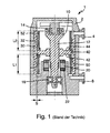
- Fig. 1 shows a longitudinal section through a belonging to the prior art vacuum pump 1.
- a suction port 4 is provided, is sucked through the gas in the vacuum pump 1. After compression, the gas is expelled from the vacuum pump 1 through an outlet 6.
- a rotor 10 which generates the pumping action together with a stator 30.
- the rotor 10 has a shaft 12, whose end facing the suction opening 4 is supported by a permanent magnet bearing 14. The opposite end is from a rolling bearing 16 supported.
- This bearing assembly has over other, also possible types of bearings, such as the flying bearing with bearings on the opposite side of the intake, the advantage that a lubricant-free bearing is used on the suction side and due to the rotor dynamic simpler storage narrow column and a shorter overall length can be achieved.
- a permanent magnet 20 is provided, which cooperates with an energized drive coil.
- the rotor 10 is set in a sufficiently fast speed. This is measured according to the pumping principle used and, with molecular principles, is generally around 10,000 revolutions per minute.
- the stator 30 has one or a plurality of helical channels 30 on its surface facing the rotor.
- a hub 40 is attached on the shaft 12. It has a first side 42 and a second side 44 opposite this first side 42. The second side 44 faces the suction opening.
- a first sleeve 50 is secured to the first side and a second sleeve 52 to the second side. Both sleeves 50, 52 cooperate with the stator 30 and its helical channel 32 to create a holweck pumping action.
- the gas flow leads through the suction opening into a gap S between the second sleeve 52 and the stator 30.
- the first sleeve 50 is arranged downstream in the gas flow of the second sleeve 52 and thus compresses toward the sleeve pressure.
- Fig. 2 the housing 2 is shown having the inlet 4.
- the rotating sleeve 52 is shown as well as the pump-active structure 32.
- FIG. 2 schematically shows how a gas molecule 60 hits the sleeve 52. Due to the probable direction of movement of the gas molecule 60, it may happen that the molecule does not enter the Holweck channels 32, but instead leaves the suction region 62 again in the direction of the recipient, that is, opposite to the direction of the arrow A. The resulting velocity is shown by the arrow 80.
- Fig. 3 shows a known from practice inlet flange 4, which is designed as an asymmetrically drilled inlet channel. This embodiment directs the gas molecules 60 in different directions of the inlet 4. The resulting velocity is shown by the arrow 80.
- Fig. 4 shows an inventive inlet geometry, which represents a further improvement over the prior art, in which the inlet 4 is formed widening in the direction of sleeve 52.
- the direction of movement of the molecules 60 is influenced so that they can no longer leave the suction flange of the pump 1 as far as possible in the direction of the recipient, ie counter to the direction of the arrow A and continue to remain in the pumping process.
- Fig. 5 shows a modified embodiment of the invention.
- the inlet 64 is according to Fig. 5 formed linear conically widening. Also according to this inlet geometry, the gas molecules, which abut the inner wall of the extension 64 of the inlet flange 4, move back in the direction of the pump chamber, so that the pumping speed of the pump also increases significantly.
- Fig. 6 1 shows a turbo-pumping stage 66 with a suction opening 62.
- the turbo-pumping stage has a rotor 68 with rotor blades 70.
- the gas molecules (not shown) enter into the vacuum pumping stage 66 in the direction of the arrow A. If the gas molecules are deflected by the rotor blades 70 in the direction of the outlet, they abut against the inner wall of the extension 64 of the suction port 62 and are in turn directed in the direction of the rotor 68.
- Fig. 7 shows a schematic representation of the pumping stage 66 with the rotor 68.
- the rotor 68 has rotor disks 72, 74 and stator disks 76, 78, wherein the rotor disks 72, 74 and the stator disks 76, 78 have opposite rotor and Statorbeschaufelept.
- a gas molecule which enters the suction opening 62 in the direction of the arrow A is deflected by the extension 64 of the suction opening 62 and "passes" through the pumping stage 66 and exits the pumping stage 66 in the direction of the arrow B.
Landscapes
- Engineering & Computer Science (AREA)
- Mechanical Engineering (AREA)
- General Engineering & Computer Science (AREA)
- Non-Positive Displacement Air Blowers (AREA)
Abstract
Vakuumpumpe oder Vakuumpumpstufe mit einem Gehäuse, welches wenigstens einen Einlass aufweist, mit einem Rotor, welcher eine Welle aufweist, wobei der Einlass radial zur Welle angeordnet ist, bei dem der Einlass in Richtung Welle sich erweiternd ausgebildet ist.Vacuum pump or vacuum pumping stage with a housing having at least one inlet, with a rotor having a shaft, wherein the inlet is arranged radially to the shaft, wherein the inlet is formed widening in the direction of the shaft.
Description
Die Erfindung betrifft eine Vakuumpumpe oder Vakuumpumpstufe mit einem Gehäuse, welches wenigstens einen Einlass aufweist.The invention relates to a vacuum pump or vacuum pump stage with a housing which has at least one inlet.
Molekulare Pumpprinzipien sind aus der Vakuumtechnik aufgrund der vielfältigen Anwendungen bei der Erzeugung industrieller Vakua nicht mehr wegzudenken. Letztlich gründet sich der Pumpeffekt auf den Impulsübertrag einer schnell bewegten Fläche auf Gasmoleküle, wodurch der statistischen thermischen Bewegung eine gerichtete Bewegung hinzuaddiert wird.Molecular pumping principles have become an indispensable part of vacuum technology due to the manifold applications in the production of industrial vacuums. Ultimately, the pumping effect is based on the momentum transfer of a rapidly moving surface to gas molecules, adding directional motion to the statistical thermal motion.
Rotierende Hülsen haben sich in Vakuumpumpen bewährt, beispielsweise in Form einer Holweckpumpstufe. Eine oder eine Mehrzahl von Hülsen wird einseitig an einer Nabe befestigt, die ihrerseits auf einer Welle angeordnet ist. Einen solchen Aufbau zeigt beispielsweise die
In einigen Anwendungsfällen ist der Einlass nicht wie bei der zum Stand der Technik (
Bei diesen zum Stand der Technik gehörenden Pumpen oder Pumpstufen tritt der Nachteil auf, dass in Anbetracht der wahrscheinlichen Bewegungsrichtung eines Gasmoleküles es dazu kommen kann, dass das Molekül nicht in die Holweckkanäle eintritt, sondern den Saugbereich wieder in Richtung Rezipient verlässt. Dies wirkt sich nachteilig auf das Saugvermögen aus.In these pumps or pump stages belonging to the prior art, the disadvantage arises that, in view of the probable direction of movement of a gas molecule, it may happen that the molecule does not enter the Holweck channels, but leaves the suction area again in the direction of the recipient. This has a disadvantageous effect on the pumping speed.
Zum Stand der Technik (
Diese zum Stand der Technik gehörenden Umlenkelemente weisen jedoch den Nachteil auf, dass sie technisch aufwendig sind und dass die Montage der Elemente in der Vakuumpumpe zeit- und kostenintensiv ist.However, these belonging to the prior art deflecting elements have the disadvantage that they are technically complex and that the assembly of the elements in the vacuum pump is time consuming and costly.
Das der Erfindung zugrunde liegende technische Problem besteht darin, eine Vakuumpumpe oder Vakuumpumpstufe mit einem radial angeordneten Einlass anzugeben, bei der das Saugvermögen bei unveränderter Größe des Einlasses erhöht wird.The technical problem underlying the invention is to provide a vacuum pump or vacuum pumping stage with a radially arranged inlet, in which the pumping speed is increased with an unchanged size of the inlet.
Dieses technische Problem wird durch eine Vakuumpumpe oder Vakuumpumpstufe mit den Merkmalen gemäß Anspruch 1 gelöst.This technical problem is solved by a vacuum pump or vacuum pumping stage having the features according to claim 1.
Die erfindungsgemäße Vakuumpumpe oder Vakuumpumpstufe mit einem Gehäuse, welches wenigstens einen Einlass aufweist mit einem Rotor, welcher eine Welle aufweist, wobei der Einlass radial zur Welle angeordnet ist, zeichnet sich dadurch aus, dass der Einlass in Richtung Welle sich erweiternd ausgebildet ist.The vacuum pump or vacuum pump stage according to the invention with a housing which has at least one inlet with a rotor which has a shaft, wherein the inlet is arranged radially to the shaft, is characterized in that the inlet is designed to widen in the direction of the shaft.
Durch die erfindungsgemäße Ausgestaltung des Einlasses und damit der Saugöffnung wird die Bewegungsrichtung der Moleküle derart beeinflusst, dass diese den Saugflansch der Pumpe oder Pumpstufe möglichst nicht mehr in Richtung Rezipient verlassen können und weiterhin in dem Pumpprozess verbleiben.Due to the inventive design of the inlet and thus the suction opening, the direction of movement of the molecules is influenced such that they can no longer leave the suction flange of the pump or pump stage as possible in the direction of the recipient and continue to remain in the pumping process.
Betrachtet man die wahrscheinliche Bewegungsrichtung der Gasmoleküle, nachdem diese in Kontakt zu dem sich drehenden zylindrischen Rotor waren, stellt man fest, dass die Gasmoleküle, wenn sie nicht in die Vakuumpumpe oder Vakuumpumpstufe eintreten, mit erhöhter Wahrscheinlichkeit oberhalb der Pumpstufe auf die Innenwand des Einlasses treffen. Die weitere Bewegung der Gasmoleküle ist mit der üblichen Wahrscheinlichkeitsverteilung behaftet.Considering the likely direction of movement of the gas molecules after they have been in contact with the rotating cylindrical rotor, it is found that the gas molecules, unless they enter the vacuum pump or vacuum pump stage, are more likely to hit the inner wall of the inlet above the pumping stage , The further movement of the gas molecules is associated with the usual probability distribution.
Durch die erfindungsgemäße Ausgestaltung des Einlasses, nämlich in Richtung Welle sich erweiternd, werden die Gasmoleküle, die auf diese Innenwand treffen, in Richtung der sich drehenden Hülse nach dem Auftreffen auf die Innenwand abgelenkt und treten mit hoher Wahrscheinlichkeit in die Vakuumpumpe oder Vakuumpumpstufe ein. Hierdurch wird die Anzahl der Gasmoleküle, die nicht unmittelbar in den Pumpbereich der Vakuumpumpe oder Vakuumpumpstufe eintreten, nach einem Aufprall auf der Innenwand des sich erweiternden Einlasses mit großer Wahrscheinlichkeit dem Pumpenbereich der Vakuumpumpe oder Vakuumpumpstufe zugeführt, so dass sich hierdurch das Saugvermögen der Vakuumpumpe oder Vakuumpumpstufe signifikant erhöht.As a result of the design of the inlet according to the invention, namely widening in the direction of the shaft, the gas molecules meeting this inner wall are deflected in the direction of the rotating sleeve after hitting the inner wall and are very likely to enter the vacuum pump or vacuum pump stage. As a result, the number of gas molecules that do not enter directly into the pumping area of the vacuum pump or vacuum pumping stage, after an impact on the inner wall of the expanding inlet, it is very likely to be fed to the pump region of the vacuum pump or vacuum pumping stage, thereby significantly increasing the suction capacity of the vacuum pump or vacuum pumping stage.
Das gleiche Prinzip gilt auch für den radialen Einlass in eine Turbomolekular-Pumpstufe mit gegenläufiger Rotor- und Statorscheibenbeschaufelung, in diesem Fall werden die Gasmoleküle bereits mit einer Vorzugsrichtung in den pumpaktiven Bereich eingelassen, so dass sich das Saugvermögen auch hier erhöht. Dabei kann dieser Einlass sowohl auf der Hochvakuumseite des Rotors vor oder im Bereich der ersten Rotorscheibe als auch im weiteren Verlauf der pumpaktiven Struktur an einer beliebigen Stelle zur Bildung eines Zusatzeinlasses für eine Split-Flow-Pumpe liegen.The same principle also applies to the radial inlet into a turbomolecular pumping stage with counter-rotating rotor and stator disk blading, in which case the gas molecules are already admitted into the pump-active region with a preferred direction, so that the pumping speed also increases here. In this case, this inlet can be located either on the high-vacuum side of the rotor in front of or in the region of the first rotor disk and also in the further course of the pump-active structure at any point to form an additional inlet for a split-flow pump.
Durch die erfindungsgemäße Ausgestaltung wird nicht nur die Wahrscheinlichkeit erhöht, dass ein Gasmolekül erfolgreich in den pumpaktiven Bereich eintritt, sondern auch, dass ein Gasmolekül, welches sich bereits im pumpaktiven Bereich befand, bei einem nicht erwünschten Austritt aus dem pumpaktiven Bereich in den Einlasskanal danach erneut zurück in den pumpaktiven Bereich geleitet wird, so dass es trotzdem gefördert werden kann und damit das Saugvermögen zusätzlich erhöht wird.The embodiment according to the invention not only increases the probability that a gas molecule successfully enters the pump-active region, but also that a gas molecule, which was already in the pump-active region, re-enters the inlet channel after an undesired exit from the pump-active region is returned to the pump active area, so that it can still be promoted and thus the pumping speed is additionally increased.
Gemäß einer vorteilhaften Ausführungsform der Erfindung weist die Vakuumpumpe wenigstens eine Holweckstufe mit einteiliger Welle und umgebenden Stator auf, wobei die fördernde Struktur auf einem der beiden Teile liegt, oder wenigstens eine Kreuzgewinde-Holweckstufe mit einteiliger Welle, wobei die fördernde Struktur eine gegenläufige Gewindestruktur darstellt oder einen Turbo-Rotor einer Turbo-Pumpe, wobei die fördernde Struktur mindestens eine Turbo-Rotorscheibe und eine Turbo-Statorscheibe enthält. Die erfindungsgemäße Ausführungsform mit dem sich in Richtung Welle erweiternden Einlass ist bei diesen Vakuumpumpen besonders vorteilhaft einsetzbar.According to an advantageous embodiment of the invention, the vacuum pump has at least one Holweckstufe with one-piece shaft and surrounding stator, wherein the promotional structure is located on one of the two parts, or at least a Kreuzgewinde Holweckstufe with one-piece shaft, wherein the promotional structure is an opposing thread structure or a turbo-rotor of a turbo pump, wherein the promotional structure at least one Turbo rotor disc and a turbo stator includes. The embodiment according to the invention with the inlet widening in the direction of the shaft can be used particularly advantageously with these vacuum pumps.
Eine andere vorteilhafte Ausführungsform der Erfindung sieht vor, dass die Vakuumpumpstufe als eine Holweckstufe mit einteiliger Welle und umgebenden Stator ausgebildet ist, wobei die fördernde Struktur auf einem der beiden Teile liegt, oder als eine Kreuzgewinde-Holweckstufe mit einteiliger Welle, wobei die fördernde Struktur eine gegenläufige Gewindestruktur darstellt, ausgebildet ist, oder einen Turbo-Rotor einer Turbo-Pumpe, wobei die fördernde Struktur mindestens eine Turbo-Rotor- und Statorscheibe enthält, aufweist. Auch bei diesen Vakuumpumpstufen ist die erfindungsgemäße Ausführungsform mit dem sich in Richtung Welle erweiternden Einlass besonders vorteilhaft einsetzbar.Another advantageous embodiment of the invention provides that the vacuum pumping stage is designed as a Holweckstufe with one-piece shaft and surrounding stator, wherein the promotional structure is located on one of the two parts, or as a cross-thread Holweckstufe with one-piece shaft, wherein the promotional structure a represents opposing threaded structure, is formed, or a turbo rotor of a turbo-pump, wherein the promotional structure includes at least one turbo rotor and stator. Even with these vacuum pumping stages, the embodiment according to the invention can be used particularly advantageously with the inlet widening in the direction of the shaft.
Eine weitere mögliche Ausführungsform der Erfindung sieht vor, dass die Vakuumpumpe oder Vakuumpumpstufe wenigstens eine Holweck-Pumpstufe aufweist mit einem Rotor, welcher eine Welle, eine mit der Welle verbundene Nabe und eine mit der Nabe verbundene und zur Welle konzentrische Hülse aufweist, und dass der Einlass in Richtung Hülse sich erweiternd ausgebildet ist. Bei dieser Ausführungsform werden die Gasmoleküle, die auf diese Innenwand treffen, in Richtung der sich drehenden Hülse nach dem Auftreffen auf die Innenwand abgelenkt und treten mit hoher Wahrscheinlichkeit in die Vakuumpumpe oder Vakuumpumpstufe ein.A further possible embodiment of the invention provides that the vacuum pump or vacuum pump stage has at least one Holweck pumping stage with a rotor having a shaft, a hub connected to the shaft and a sleeve connected to the hub and concentric with the shaft, and that the Inlet towards sleeve is formed widening. In this embodiment, the gas molecules impinging on this inner wall are deflected towards the rotating sleeve after hitting the inner wall and are likely to enter the vacuum pump or vacuum pumping stage.
Gemäß einer vorteilhaften Ausführungsform der Erfindung ist der Einlass als ein Gas durch den Einlass in die Drehrichtung des Rotors angeordnete Kanäle des Rotors leitender Einlass ausgebildet. Diese Ausführungsform weist den Vorteil auf, dass die durch die Ansaugöffnung eintretenden Gasmoleküle unmittelbar in die in Drehrichtung des Rotors angeordneten Kanäle, beispielsweise eines Holweckstators, gefördert wird. Diese unmittelbare Zuführung erhöht ebenfalls das Saugvermögen der Vakuumpumpe oder Vakuumpumpstufe.According to an advantageous embodiment of the invention, the inlet is designed as a channel of the rotor-conducting inlet disposed as a gas through the inlet in the direction of rotation of the rotor. This embodiment has the advantage that the entering through the suction port Gas molecules is conveyed directly into the arranged in the direction of rotation of the rotor channels, such as a Holweckstators. This direct feed also increases the suction capacity of the vacuum pump or vacuum pump stage.
Gemäß einer besonders bevorzugten Ausführungsform der Erfindung ist der Einlass in Drehrichtung des Rotors sich erweiternd ausgebildet.According to a particularly preferred embodiment of the invention, the inlet in the direction of rotation of the rotor is designed to widen.
Da die Gasmoleküle, wenn sie in Kontakt mit der sich drehenden Hülse getreten sind, in Richtung der Drehrichtung abgelenkt werden, ist es ausreichend, den Einlass in dieser Richtung sich erweiternd auszugestalten. Die gegenüberliegende Seite des Einlassflansches kann, wie aus dem Stand der Technik bekannt, teilzylinderförmig ausgebildet sein.Since the gas molecules, when in contact with the rotating sleeve, are deflected in the direction of rotation, it is sufficient to make the inlet widening in this direction. The opposite side of the inlet flange may, as known from the prior art, be formed partially cylindrical.
Gemäß einer weiteren vorteilhaften Ausgestaltung der Erfindung ist der Einlass im Querschnitt mit einer gekrümmten Außenkontur sich erweiternd ausgebildet. Der Einlass kann grundsätzlich auch mit einer geraden Außenkontur sich erweiternd ausgebildet sein. Die gekrümmte Außenkontur weist jedoch den Vorteil auf, dass die Kontur derart angepasst werden kann, dass die Gasmoleküle mit der größten Wahrscheinlichkeit nach einem Aufprall an der Außenkontur in Richtung der sich drehenden Hülse abgelenkt werden und nicht in die entgegengesetzte Richtung. Gleichzeitig erlaubt die gekrümmte Außenkontur eine geringere Erweiterung des Einlasses in Richtung des Pumpenraumes als dies bei einer geraden Außenkontur der Fall ist.According to a further advantageous embodiment of the invention, the inlet is formed widening in cross section with a curved outer contour. In principle, the inlet can also be formed widening with a straight outer contour. However, the curved outer contour has the advantage that the contour can be adjusted in such a way that the gas molecules are deflected with the greatest probability after an impact on the outer contour in the direction of the rotating sleeve and not in the opposite direction. At the same time the curved outer contour allows a smaller extension of the inlet in the direction of the pump chamber than is the case with a straight outer contour.
Der Einlass kann, wie schon ausgeführt, im Querschnitt sich linear konisch erweiternd ausgebildet sein. Diese Ausführungsform ist einfach herstellbar und das Saugvermögen der Vakuumpumpe oder Vakuumpumpstufe wird trotzdem erhöht.The inlet can, as already stated, be designed to widen in a linear conical manner in cross-section. This embodiment is easy to manufacture and the suction capacity of the vacuum pump or vacuum pump stage is increased anyway.
Gemäß einer möglichen weiteren Ausführungsform der Erfindung ist der Einlass an allen Richtungen sich erweiternd ausgebildet. Es ist jedoch auch möglich, dass der Einlass lediglich in Drehrichtung des Rotors sich erweiternd ausgebildet ist. Wird der Einlass lediglich an der Seite, die in Drehrichtung des Rotors angeordnet ist, sich erweiternd ausgebildet, vermindern sich die Kosten für die sich erweiternde Ausgestaltung des Einlasses.According to a possible further embodiment of the invention, the inlet is designed to widen in all directions. However, it is also possible that the inlet is formed widening only in the direction of rotation of the rotor. If the inlet is formed widening only on the side which is arranged in the direction of rotation of the rotor, the costs for the widening configuration of the inlet are reduced.
Vorteilhaft ist die Vakuumpumpe als Molekularvakuumpumpe, insbesondere als Holweckpumpe ausgebildet. Ebenfalls ist die Vakuumpumpstufe vorteilhaft als Molekularvakuumpumpstufe vorteilhaft als Holweckpumpstufe ausgebildet.Advantageously, the vacuum pump is designed as a molecular vacuum pump, in particular as a Holweck pump. Likewise, the vacuum pump stage is advantageously designed as a molecular vacuum pump stage advantageously as a Holweck pump stage.
Die erfindungsgemäße Ausbildung des Einlassflansches lässt sich auf Holweckpumpstufen anwenden, bei denen die pumpaktiven Flächen im Stator angeordnet sind. Gleichermaßen lässt sich die Erfindung auch auf Holweckpumpstufen anwenden, bei denen die pumpaktiven Strukturen auf der Hülse, das heißt auf dem Rotor angeordnet sind. Weiterhin lässt sich die Erfindung auch auf Kreuzgewinde-Holweckpumpstufen anwenden, bei denen pumpaktive Strukturen sowohl auf dem Rotor als auch Stator angeordnet sind. Auch lässt sich die Erfindung auf Turbomolekular-Pumpstufen anwenden, bei denen die pumpaktive Struktur aus Rotor- und Statorschaufeln besteht.The inventive design of the inlet flange can be applied to Holweckpumpstufen, in which the pump-active surfaces are arranged in the stator. Likewise, the invention can also be applied to Holweckpumpstufen, in which the pump-active structures on the sleeve, that are arranged on the rotor. Furthermore, the invention can also be applied to cross-thread Holweckpumpstufen in which pump-active structures are arranged both on the rotor and stator. Also, the invention can be applied to turbomolecular pumping stages in which the pump-active structure consists of rotor and stator blades.
Weitere Merkmale und Vorteile der Erfindung ergeben sich anhand der zugehörigen Zeichnung, in der ein Ausführungsbeispiel eines erfindungsgemäßen Einlasses nur beispielhaft dargestellt ist. In der Zeichnung zeigen:
- Fig. 1
- einen Querschnitt durch eine Vakuumpumpe;
- Fig. 2
- eine Darstellung der Bewegung der Gasmoleküle in einem Einlass gemäß dem Stand der Technik;
- Fig. 3
- eine Darstellung der Bewegung der Gasmoleküle in einem zum Stand der Technik gehörenden Einlass;
- Fig. 4
- eine erfindungsgemäße Ausgestaltung eines Einlasses im Querschnitt;
- Fig. 5
- ein geändertes Ausführungsbeispiel eines Einlasses im Querschnitt;
- Fig. 6
- ein geändertes Ausführungsbeispiel eines Einlasses einer Turbomolekularpumpstufe mit einem Rotor im Querschnitt;
- Fig. 7
- eine schematische Darstellung der Turbopumpstufe der
Fig. 6 im Längsschnitt.
- Fig. 1
- a cross section through a vacuum pump;
- Fig. 2
- a representation of the movement of the gas molecules in an inlet according to the prior art;
- Fig. 3
- a representation of the movement of the gas molecules in a prior art inlet;
- Fig. 4
- an inventive embodiment of an inlet in cross section;
- Fig. 5
- a modified embodiment of an inlet in cross section;
- Fig. 6
- a modified embodiment of an inlet of a turbomolecular pumping stage with a rotor in cross section;
- Fig. 7
- a schematic representation of the turbo pumping stage of
Fig. 6 in longitudinal section.
Innerhalb der Vakuumpumpe 1 ist ein Rotor 10 vorgesehen, der zusammen mit einem Stator 30 die Pumpwirkung erzeugt. Der Rotor 10 weist eine Welle 12 auf, deren der Ansaugöffnung 4 zugewandtes Ende von einem Permanentmagnetlager 14 getragen wird. Das gegenüberliegende Ende wird von einem Wälzlager 16 unterstützt. Diese Lageranordnung besitzt gegenüber anderen, ebenfalls möglichen Lagerarten, wie der fliegenden Lagerung mit Wälzlagern auf der der Ansaugöffnung gegenüberliegenden Seite, den Vorteil, dass ein schmiermittelfreies Lager ansaugseitig eingesetzt wird und aufgrund der rotordynamisch einfacheren Lagerung enge Spalte und eine kürzere Baulänge erreicht werden.Within the vacuum pump 1, a
Auf der Welle ist ein Permanentmagnet 20 vorgesehen, der mit einer bestromten Antriebsspule zusammenwirkt. Hierdurch wird der Rotor 10 in eine ausreichend schnelle Drehzahl versetzt. Diese bemisst sich nach dem verwendeten Pumpprinzip und liegt bei molekularen Prinzipien in der Regel bei einigen 10.000 Umdrehungen pro Minute.On the shaft, a permanent magnet 20 is provided, which cooperates with an energized drive coil. As a result, the
Der Stator 30 weist auf seiner dem Rotor zugewandten Oberfläche einen oder eine Mehrzahl schraubenlinienartiger Kanäle 30 auf.The
An der Welle 12 ist eine Nabe 40 befestigt. Sie weist eine erste Seite 42 und eine dieser ersten Seite 42 gegenüberliegende zweite Seite 44 auf. Die zweite Seite 44 ist der Ansaugöffnung zugewandt. An der ersten Seite ist eine erste Hülse 50 befestigt, an der zweiten Seite eine zweite Hülse 52. Beide Hülsen 50, 52 wirken mit dem Stator 30 und dessen schraubenlinienartigen Kanal 32 zur Erzeugung einer Pumpwirkung nach Holweck zusammen. Der Gasstrom führt durch die Ansaugöffnung in einen Spalt S zwischen zweiter Hülse 52 und Stator 30. Die erste Hülse 50 ist im Gasstrom der zweiten Hülse 52 nachfolgend angeordnet und verdichtet damit zum Hülsendruck hin. Durch die Verwendung der Hülsen 50 und 52 zusammen mit der beschriebenen Gasführung wirken sich Fertigungstoleranzen im geringeren Maße auf den Spalt S aus, so dass dieser enger als bei einer vergleichbaren einzelnen Hülse ausgeführt wird, deren Länge der Summe der Längen der beiden Hülsen L1 und L2 entspricht.On the
In
In der
Betrachtet man gemäß
Wird der Einlass 4, wie in
Ein Gasmolekül, welches in Richtung des Pfeiles A in die Ansaugöffnung 62 eintritt, wird von der Erweiterung 64 der Ansaugöffnung 62 entsprechend abgelenkt und "durchläuft" die Pumpstufe 66 und tritt aus der Pumpstufe 66 in Richtung des Pfeiles B aus.A gas molecule which enters the
- 11
- Vakuumpumpevacuum pump
- 22
- Gehäusecasing
- 44
- Ansaugöffnungsuction
- 66
- Auslassoutlet
- 1010
- Rotorrotor
- 1212
- Wellewave
- 1414
- PermanentmagnetlagerPermanent magnetic bearings
- 1616
- Wälzlagerroller bearing
- 2020
- Permanentmagnetpermanent magnet
- 3030
- Statorstator
- 3232
- Kanäle im StatorChannels in the stator
- 4040
- Nabehub
- 4242
- erste Seite der Nabefirst side of the hub
- 4444
- zweite Seite der Nabesecond side of the hub
- 5050
- erste Hülsefirst sleeve
- 5252
- zweite Hülsesecond sleeve
- 6060
- Molekülmolecule
- 6262
- Ansaugöffnungsuction
- 6464
-
Erweiterung des Einlassflansches 4Extension of the
inlet flange 4 - 6666
- TurbopumpstufeTurbo pump stage
- 6868
- Rotorrotor
- 7070
- Rotorschaufelnrotor blades
- 7272
- Rotorscheiberotor disc
- 7474
- Rotorscheiberotor disc
- 7676
- Statorscheibestator
- 7878
- Statorscheibestator
- 8080
- Pfeil (resultierende Geschwindigkeit)Arrow (resulting speed)
- AA
- Pfeilarrow
- BB
- Pfeilarrow
Claims (13)
dadurch gekennzeichnet, dass der Einlass (4) in Richtung Welle (12) sich erweiternd ausgebildet ist.Vacuum pump or vacuum pump stage with a housing having at least one inlet, with a rotor having a shaft, wherein the inlet is arranged radially to the shaft,
characterized in that the inlet (4) in the direction of the shaft (12) is formed widening.
Applications Claiming Priority (1)
| Application Number | Priority Date | Filing Date | Title |
|---|---|---|---|
| DE102013114290.7A DE102013114290A1 (en) | 2013-12-18 | 2013-12-18 | vacuum pump |
Publications (3)
| Publication Number | Publication Date |
|---|---|
| EP2886870A1 true EP2886870A1 (en) | 2015-06-24 |
| EP2886870B1 EP2886870B1 (en) | 2017-12-20 |
| EP2886870B2 EP2886870B2 (en) | 2020-12-23 |
Family
ID=52023216
Family Applications (1)
| Application Number | Title | Priority Date | Filing Date |
|---|---|---|---|
| EP14196002.1A Active EP2886870B2 (en) | 2013-12-18 | 2014-12-03 | Vacuum pump with improved inlet geometry |
Country Status (4)
| Country | Link |
|---|---|
| US (1) | US20150167679A1 (en) |
| EP (1) | EP2886870B2 (en) |
| JP (1) | JP6118784B2 (en) |
| DE (1) | DE102013114290A1 (en) |
Families Citing this family (1)
| Publication number | Priority date | Publication date | Assignee | Title |
|---|---|---|---|---|
| JP6578838B2 (en) * | 2015-09-15 | 2019-09-25 | 株式会社島津製作所 | Vacuum pump and mass spectrometer |
Citations (7)
| Publication number | Priority date | Publication date | Assignee | Title |
|---|---|---|---|---|
| DE19848406A1 (en) * | 1997-10-21 | 1999-05-20 | Varian Associates | Molecular pump with ribbed rotor construction |
| US6450772B1 (en) * | 1999-10-18 | 2002-09-17 | Sarcos, Lc | Compact molecular drag vacuum pump |
| EP1243796A2 (en) * | 2001-03-24 | 2002-09-25 | Pfeiffer Vacuum GmbH | Vacuum pump |
| EP1302667A1 (en) * | 2001-10-15 | 2003-04-16 | The BOC Group plc | Vacuum pumps |
| EP2385257A2 (en) * | 2010-05-08 | 2011-11-09 | Pfeiffer Vacuum Gmbh | Vacuum pump stage |
| DE202010012795U1 (en) | 2010-09-21 | 2012-01-13 | Oerlikon Leybold Vacuum Gmbh | vacuum pump |
| DE102011112689A1 (en) | 2011-09-05 | 2013-03-07 | Pfeiffer Vacuum Gmbh | vacuum pump |
Family Cites Families (18)
| Publication number | Priority date | Publication date | Assignee | Title |
|---|---|---|---|---|
| JPS6146492A (en) | 1984-08-11 | 1986-03-06 | Mitsuwa Seiki Co Ltd | Molecular pump |
| JPH0213195U (en) * | 1988-06-30 | 1990-01-26 | ||
| FR2641582B1 (en) * | 1989-01-09 | 1991-03-22 | Cit Alcatel | GAEDE CHANNEL TYPE VACUUM PUMP |
| JPH0475196U (en) * | 1990-11-09 | 1992-06-30 | ||
| DE4331589C2 (en) | 1992-12-24 | 2003-06-26 | Pfeiffer Vacuum Gmbh | Vacuum pumping system |
| JPH0717986U (en) * | 1993-09-08 | 1995-03-31 | 二国機械工業株式会社 | Vortex pump |
| DE19508566A1 (en) | 1995-03-10 | 1996-09-12 | Balzers Pfeiffer Gmbh | Molecular vacuum pump with cooling gas device and method for its operation |
| DE19821634A1 (en) | 1998-05-14 | 1999-11-18 | Leybold Vakuum Gmbh | Friction vacuum pump with staged rotor and stator |
| JP3961155B2 (en) * | 1999-05-28 | 2007-08-22 | Bocエドワーズ株式会社 | Vacuum pump |
| DE19930952A1 (en) * | 1999-07-05 | 2001-01-11 | Pfeiffer Vacuum Gmbh | Vacuum pump |
| GB9921983D0 (en) | 1999-09-16 | 1999-11-17 | Boc Group Plc | Improvements in vacuum pumps |
| GB2360066A (en) | 2000-03-06 | 2001-09-12 | Boc Group Plc | Vacuum pump |
| JP2005042709A (en) * | 2003-07-10 | 2005-02-17 | Ebara Corp | Vacuum pump |
| GB0414316D0 (en) | 2004-06-25 | 2004-07-28 | Boc Group Plc | Vacuum pump |
| DE202005019644U1 (en) | 2005-12-16 | 2007-04-26 | Leybold Vacuum Gmbh | Turbo molecular pump, with a main inflow and at least one intermediate inflow, has a floating rotor supported by active magnet radial and radial-axial bearings |
| DE102008024764A1 (en) | 2008-05-23 | 2009-11-26 | Oerlikon Leybold Vacuum Gmbh | Multi-stage vacuum pump |
| DE102009035332A1 (en) | 2009-07-30 | 2011-02-03 | Pfeiffer Vacuum Gmbh | vacuum pump |
| DE102011112691A1 (en) | 2011-09-05 | 2013-03-07 | Pfeiffer Vacuum Gmbh | vacuum pump |
-
2013
- 2013-12-18 DE DE102013114290.7A patent/DE102013114290A1/en active Pending
-
2014
- 2014-12-03 EP EP14196002.1A patent/EP2886870B2/en active Active
- 2014-12-05 JP JP2014246652A patent/JP6118784B2/en active Active
- 2014-12-16 US US14/571,355 patent/US20150167679A1/en not_active Abandoned
Patent Citations (7)
| Publication number | Priority date | Publication date | Assignee | Title |
|---|---|---|---|---|
| DE19848406A1 (en) * | 1997-10-21 | 1999-05-20 | Varian Associates | Molecular pump with ribbed rotor construction |
| US6450772B1 (en) * | 1999-10-18 | 2002-09-17 | Sarcos, Lc | Compact molecular drag vacuum pump |
| EP1243796A2 (en) * | 2001-03-24 | 2002-09-25 | Pfeiffer Vacuum GmbH | Vacuum pump |
| EP1302667A1 (en) * | 2001-10-15 | 2003-04-16 | The BOC Group plc | Vacuum pumps |
| EP2385257A2 (en) * | 2010-05-08 | 2011-11-09 | Pfeiffer Vacuum Gmbh | Vacuum pump stage |
| DE202010012795U1 (en) | 2010-09-21 | 2012-01-13 | Oerlikon Leybold Vacuum Gmbh | vacuum pump |
| DE102011112689A1 (en) | 2011-09-05 | 2013-03-07 | Pfeiffer Vacuum Gmbh | vacuum pump |
Also Published As
| Publication number | Publication date |
|---|---|
| JP2015117697A (en) | 2015-06-25 |
| EP2886870B1 (en) | 2017-12-20 |
| US20150167679A1 (en) | 2015-06-18 |
| DE102013114290A1 (en) | 2015-06-18 |
| EP2886870B2 (en) | 2020-12-23 |
| JP6118784B2 (en) | 2017-04-19 |
Similar Documents
| Publication | Publication Date | Title |
|---|---|---|
| EP2295812B1 (en) | Vacuum pump | |
| DE2412624C2 (en) | Molecular vacuum pump arrangement | |
| DE3932228A1 (en) | TURBOVACUUM PUMP | |
| DE602004008089T2 (en) | VACUUM PUMP | |
| EP1706645B1 (en) | Multi-stage friction vacuum pump | |
| EP2933497B1 (en) | Vacuum pump | |
| DE102009021620B4 (en) | Vacuum pump | |
| WO2009141222A1 (en) | Multi-stage vacuum pump | |
| EP1067290A2 (en) | Vacuum pump | |
| EP3088743B1 (en) | Side-channel vacuum pump stage with a stripper that is slanted on the suction side | |
| EP2886870B1 (en) | Vacuum pump with improved inlet geometry | |
| EP3608545B1 (en) | Vacuum pump | |
| EP2594803A1 (en) | Friction vacuum pump | |
| EP2565464B1 (en) | Vacuum pump | |
| WO2010105908A1 (en) | Multi-inlet vacuum pump | |
| EP3032107B1 (en) | Turbomolecular pump | |
| EP3045728B1 (en) | Spiral vacuum pump | |
| EP2902637B1 (en) | Vacuum pump | |
| EP3734078A2 (en) | Turbomolecular pump and method of manufacturing a stator disc for such a pump | |
| DE102013112185B4 (en) | Vacuum pump and vacuum pump with at least one turbomolecular pump stage | |
| EP3767109B1 (en) | Vacuum system | |
| EP3577346B1 (en) | Turbo compressor with integrated flow channels | |
| DE102013022539B3 (en) | vacuum pump | |
| EP4194700A1 (en) | Vacuum pump with a holweck pump stage with variable holweck geometry | |
| DE202017103826U1 (en) | Turbo compressor with integrated flow channels |
Legal Events
| Date | Code | Title | Description |
|---|---|---|---|
| PUAI | Public reference made under article 153(3) epc to a published international application that has entered the european phase |
Free format text: ORIGINAL CODE: 0009012 |
|
| 17P | Request for examination filed |
Effective date: 20141203 |
|
| AK | Designated contracting states |
Kind code of ref document: A1 Designated state(s): AL AT BE BG CH CY CZ DE DK EE ES FI FR GB GR HR HU IE IS IT LI LT LU LV MC MK MT NL NO PL PT RO RS SE SI SK SM TR |
|
| AX | Request for extension of the european patent |
Extension state: BA ME |
|
| R17P | Request for examination filed (corrected) |
Effective date: 20151126 |
|
| RBV | Designated contracting states (corrected) |
Designated state(s): AL AT BE BG CH CY CZ DE DK EE ES FI FR GB GR HR HU IE IS IT LI LT LU LV MC MK MT NL NO PL PT RO RS SE SI SK SM TR |
|
| GRAP | Despatch of communication of intention to grant a patent |
Free format text: ORIGINAL CODE: EPIDOSNIGR1 |
|
| STAA | Information on the status of an ep patent application or granted ep patent |
Free format text: STATUS: GRANT OF PATENT IS INTENDED |
|
| INTG | Intention to grant announced |
Effective date: 20170908 |
|
| GRAS | Grant fee paid |
Free format text: ORIGINAL CODE: EPIDOSNIGR3 |
|
| GRAA | (expected) grant |
Free format text: ORIGINAL CODE: 0009210 |
|
| STAA | Information on the status of an ep patent application or granted ep patent |
Free format text: STATUS: THE PATENT HAS BEEN GRANTED |
|
| AK | Designated contracting states |
Kind code of ref document: B1 Designated state(s): AL AT BE BG CH CY CZ DE DK EE ES FI FR GB GR HR HU IE IS IT LI LT LU LV MC MK MT NL NO PL PT RO RS SE SI SK SM TR |
|
| REG | Reference to a national code |
Ref country code: GB Ref legal event code: FG4D Free format text: NOT ENGLISH |
|
| REG | Reference to a national code |
Ref country code: CH Ref legal event code: EP |
|
| REG | Reference to a national code |
Ref country code: IE Ref legal event code: FG4D Free format text: LANGUAGE OF EP DOCUMENT: GERMAN |
|
| REG | Reference to a national code |
Ref country code: AT Ref legal event code: REF Ref document number: 956655 Country of ref document: AT Kind code of ref document: T Effective date: 20180115 |
|
| REG | Reference to a national code |
Ref country code: DE Ref legal event code: R096 Ref document number: 502014006638 Country of ref document: DE |
|
| REG | Reference to a national code |
Ref country code: NL Ref legal event code: MP Effective date: 20171220 |
|
| PG25 | Lapsed in a contracting state [announced via postgrant information from national office to epo] |
Ref country code: NO Free format text: LAPSE BECAUSE OF FAILURE TO SUBMIT A TRANSLATION OF THE DESCRIPTION OR TO PAY THE FEE WITHIN THE PRESCRIBED TIME-LIMIT Effective date: 20180320 Ref country code: LT Free format text: LAPSE BECAUSE OF FAILURE TO SUBMIT A TRANSLATION OF THE DESCRIPTION OR TO PAY THE FEE WITHIN THE PRESCRIBED TIME-LIMIT Effective date: 20171220 Ref country code: FI Free format text: LAPSE BECAUSE OF FAILURE TO SUBMIT A TRANSLATION OF THE DESCRIPTION OR TO PAY THE FEE WITHIN THE PRESCRIBED TIME-LIMIT Effective date: 20171220 Ref country code: SE Free format text: LAPSE BECAUSE OF FAILURE TO SUBMIT A TRANSLATION OF THE DESCRIPTION OR TO PAY THE FEE WITHIN THE PRESCRIBED TIME-LIMIT Effective date: 20171220 |
|
| REG | Reference to a national code |
Ref country code: LT Ref legal event code: MG4D |
|
| PG25 | Lapsed in a contracting state [announced via postgrant information from national office to epo] |
Ref country code: LV Free format text: LAPSE BECAUSE OF FAILURE TO SUBMIT A TRANSLATION OF THE DESCRIPTION OR TO PAY THE FEE WITHIN THE PRESCRIBED TIME-LIMIT Effective date: 20171220 Ref country code: RS Free format text: LAPSE BECAUSE OF FAILURE TO SUBMIT A TRANSLATION OF THE DESCRIPTION OR TO PAY THE FEE WITHIN THE PRESCRIBED TIME-LIMIT Effective date: 20171220 Ref country code: GR Free format text: LAPSE BECAUSE OF FAILURE TO SUBMIT A TRANSLATION OF THE DESCRIPTION OR TO PAY THE FEE WITHIN THE PRESCRIBED TIME-LIMIT Effective date: 20180321 Ref country code: BG Free format text: LAPSE BECAUSE OF FAILURE TO SUBMIT A TRANSLATION OF THE DESCRIPTION OR TO PAY THE FEE WITHIN THE PRESCRIBED TIME-LIMIT Effective date: 20180320 Ref country code: HR Free format text: LAPSE BECAUSE OF FAILURE TO SUBMIT A TRANSLATION OF THE DESCRIPTION OR TO PAY THE FEE WITHIN THE PRESCRIBED TIME-LIMIT Effective date: 20171220 |
|
| PG25 | Lapsed in a contracting state [announced via postgrant information from national office to epo] |
Ref country code: NL Free format text: LAPSE BECAUSE OF FAILURE TO SUBMIT A TRANSLATION OF THE DESCRIPTION OR TO PAY THE FEE WITHIN THE PRESCRIBED TIME-LIMIT Effective date: 20171220 |
|
| PG25 | Lapsed in a contracting state [announced via postgrant information from national office to epo] |
Ref country code: SK Free format text: LAPSE BECAUSE OF FAILURE TO SUBMIT A TRANSLATION OF THE DESCRIPTION OR TO PAY THE FEE WITHIN THE PRESCRIBED TIME-LIMIT Effective date: 20171220 Ref country code: ES Free format text: LAPSE BECAUSE OF FAILURE TO SUBMIT A TRANSLATION OF THE DESCRIPTION OR TO PAY THE FEE WITHIN THE PRESCRIBED TIME-LIMIT Effective date: 20171220 Ref country code: CY Free format text: LAPSE BECAUSE OF FAILURE TO SUBMIT A TRANSLATION OF THE DESCRIPTION OR TO PAY THE FEE WITHIN THE PRESCRIBED TIME-LIMIT Effective date: 20171220 Ref country code: EE Free format text: LAPSE BECAUSE OF FAILURE TO SUBMIT A TRANSLATION OF THE DESCRIPTION OR TO PAY THE FEE WITHIN THE PRESCRIBED TIME-LIMIT Effective date: 20171220 |
|
| PG25 | Lapsed in a contracting state [announced via postgrant information from national office to epo] |
Ref country code: IS Free format text: LAPSE BECAUSE OF FAILURE TO SUBMIT A TRANSLATION OF THE DESCRIPTION OR TO PAY THE FEE WITHIN THE PRESCRIBED TIME-LIMIT Effective date: 20180420 Ref country code: PL Free format text: LAPSE BECAUSE OF FAILURE TO SUBMIT A TRANSLATION OF THE DESCRIPTION OR TO PAY THE FEE WITHIN THE PRESCRIBED TIME-LIMIT Effective date: 20171220 Ref country code: RO Free format text: LAPSE BECAUSE OF FAILURE TO SUBMIT A TRANSLATION OF THE DESCRIPTION OR TO PAY THE FEE WITHIN THE PRESCRIBED TIME-LIMIT Effective date: 20171220 Ref country code: SM Free format text: LAPSE BECAUSE OF FAILURE TO SUBMIT A TRANSLATION OF THE DESCRIPTION OR TO PAY THE FEE WITHIN THE PRESCRIBED TIME-LIMIT Effective date: 20171220 |
|
| REG | Reference to a national code |
Ref country code: DE Ref legal event code: R026 Ref document number: 502014006638 Country of ref document: DE |
|
| PG25 | Lapsed in a contracting state [announced via postgrant information from national office to epo] |
Ref country code: MT Free format text: LAPSE BECAUSE OF FAILURE TO SUBMIT A TRANSLATION OF THE DESCRIPTION OR TO PAY THE FEE WITHIN THE PRESCRIBED TIME-LIMIT Effective date: 20171220 |
|
| PLBI | Opposition filed |
Free format text: ORIGINAL CODE: 0009260 |
|
| PLAX | Notice of opposition and request to file observation + time limit sent |
Free format text: ORIGINAL CODE: EPIDOSNOBS2 |
|
| 26 | Opposition filed |
Opponent name: LEYBOLD GMBH Effective date: 20180920 |
|
| PG25 | Lapsed in a contracting state [announced via postgrant information from national office to epo] |
Ref country code: DK Free format text: LAPSE BECAUSE OF FAILURE TO SUBMIT A TRANSLATION OF THE DESCRIPTION OR TO PAY THE FEE WITHIN THE PRESCRIBED TIME-LIMIT Effective date: 20171220 |
|
| PLBB | Reply of patent proprietor to notice(s) of opposition received |
Free format text: ORIGINAL CODE: EPIDOSNOBS3 |
|
| PG25 | Lapsed in a contracting state [announced via postgrant information from national office to epo] |
Ref country code: SI Free format text: LAPSE BECAUSE OF FAILURE TO SUBMIT A TRANSLATION OF THE DESCRIPTION OR TO PAY THE FEE WITHIN THE PRESCRIBED TIME-LIMIT Effective date: 20171220 |
|
| REG | Reference to a national code |
Ref country code: CH Ref legal event code: PL |
|
| PG25 | Lapsed in a contracting state [announced via postgrant information from national office to epo] |
Ref country code: MC Free format text: LAPSE BECAUSE OF FAILURE TO SUBMIT A TRANSLATION OF THE DESCRIPTION OR TO PAY THE FEE WITHIN THE PRESCRIBED TIME-LIMIT Effective date: 20171220 Ref country code: LU Free format text: LAPSE BECAUSE OF NON-PAYMENT OF DUE FEES Effective date: 20181203 |
|
| REG | Reference to a national code |
Ref country code: IE Ref legal event code: MM4A |
|
| REG | Reference to a national code |
Ref country code: BE Ref legal event code: MM Effective date: 20181231 |
|
| PG25 | Lapsed in a contracting state [announced via postgrant information from national office to epo] |
Ref country code: FR Free format text: LAPSE BECAUSE OF NON-PAYMENT OF DUE FEES Effective date: 20181231 Ref country code: IE Free format text: LAPSE BECAUSE OF NON-PAYMENT OF DUE FEES Effective date: 20181203 |
|
| PG25 | Lapsed in a contracting state [announced via postgrant information from national office to epo] |
Ref country code: BE Free format text: LAPSE BECAUSE OF NON-PAYMENT OF DUE FEES Effective date: 20181231 |
|
| PG25 | Lapsed in a contracting state [announced via postgrant information from national office to epo] |
Ref country code: LI Free format text: LAPSE BECAUSE OF NON-PAYMENT OF DUE FEES Effective date: 20181231 Ref country code: CH Free format text: LAPSE BECAUSE OF NON-PAYMENT OF DUE FEES Effective date: 20181231 |
|
| PG25 | Lapsed in a contracting state [announced via postgrant information from national office to epo] |
Ref country code: TR Free format text: LAPSE BECAUSE OF FAILURE TO SUBMIT A TRANSLATION OF THE DESCRIPTION OR TO PAY THE FEE WITHIN THE PRESCRIBED TIME-LIMIT Effective date: 20171220 |
|
| PG25 | Lapsed in a contracting state [announced via postgrant information from national office to epo] |
Ref country code: PT Free format text: LAPSE BECAUSE OF FAILURE TO SUBMIT A TRANSLATION OF THE DESCRIPTION OR TO PAY THE FEE WITHIN THE PRESCRIBED TIME-LIMIT Effective date: 20171220 |
|
| PG25 | Lapsed in a contracting state [announced via postgrant information from national office to epo] |
Ref country code: MK Free format text: LAPSE BECAUSE OF NON-PAYMENT OF DUE FEES Effective date: 20171220 Ref country code: HU Free format text: LAPSE BECAUSE OF FAILURE TO SUBMIT A TRANSLATION OF THE DESCRIPTION OR TO PAY THE FEE WITHIN THE PRESCRIBED TIME-LIMIT; INVALID AB INITIO Effective date: 20141203 |
|
| PG25 | Lapsed in a contracting state [announced via postgrant information from national office to epo] |
Ref country code: AL Free format text: LAPSE BECAUSE OF FAILURE TO SUBMIT A TRANSLATION OF THE DESCRIPTION OR TO PAY THE FEE WITHIN THE PRESCRIBED TIME-LIMIT Effective date: 20171220 |
|
| PUAH | Patent maintained in amended form |
Free format text: ORIGINAL CODE: 0009272 |
|
| STAA | Information on the status of an ep patent application or granted ep patent |
Free format text: STATUS: PATENT MAINTAINED AS AMENDED |
|
| 27A | Patent maintained in amended form |
Effective date: 20201223 |
|
| AK | Designated contracting states |
Kind code of ref document: B2 Designated state(s): AL AT BE BG CH CY CZ DE DK EE ES FI FR GB GR HR HU IE IS IT LI LT LU LV MC MK MT NL NO PL PT RO RS SE SI SK SM TR |
|
| REG | Reference to a national code |
Ref country code: DE Ref legal event code: R102 Ref document number: 502014006638 Country of ref document: DE |
|
| REG | Reference to a national code |
Ref country code: AT Ref legal event code: MM01 Ref document number: 956655 Country of ref document: AT Kind code of ref document: T Effective date: 20191203 |
|
| PG25 | Lapsed in a contracting state [announced via postgrant information from national office to epo] |
Ref country code: AT Free format text: LAPSE BECAUSE OF NON-PAYMENT OF DUE FEES Effective date: 20191203 |
|
| PGFP | Annual fee paid to national office [announced via postgrant information from national office to epo] |
Ref country code: GB Payment date: 20231102 Year of fee payment: 10 |
|
| PGFP | Annual fee paid to national office [announced via postgrant information from national office to epo] |
Ref country code: IT Payment date: 20231026 Year of fee payment: 10 Ref country code: DE Payment date: 20231102 Year of fee payment: 10 Ref country code: CZ Payment date: 20231030 Year of fee payment: 10 |