EP2884545B1 - Structure de montage d'ensemble photovoltaïque à charnière et son procédé de montage - Google Patents
Structure de montage d'ensemble photovoltaïque à charnière et son procédé de montage Download PDFInfo
- Publication number
- EP2884545B1 EP2884545B1 EP12875799.4A EP12875799A EP2884545B1 EP 2884545 B1 EP2884545 B1 EP 2884545B1 EP 12875799 A EP12875799 A EP 12875799A EP 2884545 B1 EP2884545 B1 EP 2884545B1
- Authority
- EP
- European Patent Office
- Prior art keywords
- bracket assembly
- backside
- hook
- connector member
- securing
- Prior art date
- Legal status (The legal status is an assumption and is not a legal conclusion. Google has not performed a legal analysis and makes no representation as to the accuracy of the status listed.)
- Active
Links
- 238000000034 method Methods 0.000 title claims description 5
- 238000006880 cross-coupling reaction Methods 0.000 claims description 40
- 238000001125 extrusion Methods 0.000 claims description 9
- 230000001070 adhesive effect Effects 0.000 claims description 8
- 239000000853 adhesive Substances 0.000 claims description 7
- 238000003754 machining Methods 0.000 claims description 7
- 230000013011 mating Effects 0.000 claims description 6
- 230000002441 reversible effect Effects 0.000 claims description 4
- 239000011159 matrix material Substances 0.000 claims description 3
- 238000009423 ventilation Methods 0.000 claims description 3
- 239000002023 wood Substances 0.000 claims description 2
- 238000010586 diagram Methods 0.000 description 11
- 238000004519 manufacturing process Methods 0.000 description 8
- XAGFODPZIPBFFR-UHFFFAOYSA-N aluminium Chemical compound [Al] XAGFODPZIPBFFR-UHFFFAOYSA-N 0.000 description 6
- 229910052782 aluminium Inorganic materials 0.000 description 6
- 239000002390 adhesive tape Substances 0.000 description 4
- 238000013461 design Methods 0.000 description 4
- 239000000463 material Substances 0.000 description 4
- 238000012856 packing Methods 0.000 description 3
- 229920001296 polysiloxane Polymers 0.000 description 3
- 230000004308 accommodation Effects 0.000 description 2
- 230000000712 assembly Effects 0.000 description 2
- 238000000429 assembly Methods 0.000 description 2
- 238000007664 blowing Methods 0.000 description 2
- 238000012986 modification Methods 0.000 description 2
- 230000004048 modification Effects 0.000 description 2
- 238000010248 power generation Methods 0.000 description 2
- 238000004080 punching Methods 0.000 description 2
- AZDRQVAHHNSJOQ-UHFFFAOYSA-N alumane Chemical group [AlH3] AZDRQVAHHNSJOQ-UHFFFAOYSA-N 0.000 description 1
- 238000005452 bending Methods 0.000 description 1
- 230000008878 coupling Effects 0.000 description 1
- 238000010168 coupling process Methods 0.000 description 1
- 238000005859 coupling reaction Methods 0.000 description 1
- 229910021419 crystalline silicon Inorganic materials 0.000 description 1
- 230000007812 deficiency Effects 0.000 description 1
- 230000002708 enhancing effect Effects 0.000 description 1
- 230000003116 impacting effect Effects 0.000 description 1
- 238000012423 maintenance Methods 0.000 description 1
- 239000002994 raw material Substances 0.000 description 1
- 230000003068 static effect Effects 0.000 description 1
- 238000003860 storage Methods 0.000 description 1
- 239000000126 substance Substances 0.000 description 1
- 230000002459 sustained effect Effects 0.000 description 1
- 239000005341 toughened glass Substances 0.000 description 1
- 238000012546 transfer Methods 0.000 description 1
Images


Classifications
-
- H—ELECTRICITY
- H02—GENERATION; CONVERSION OR DISTRIBUTION OF ELECTRIC POWER
- H02S—GENERATION OF ELECTRIC POWER BY CONVERSION OF INFRARED RADIATION, VISIBLE LIGHT OR ULTRAVIOLET LIGHT, e.g. USING PHOTOVOLTAIC [PV] MODULES
- H02S30/00—Structural details of PV modules other than those related to light conversion
- H02S30/20—Collapsible or foldable PV modules
-
- F—MECHANICAL ENGINEERING; LIGHTING; HEATING; WEAPONS; BLASTING
- F24—HEATING; RANGES; VENTILATING
- F24S—SOLAR HEAT COLLECTORS; SOLAR HEAT SYSTEMS
- F24S25/00—Arrangement of stationary mountings or supports for solar heat collector modules
- F24S25/10—Arrangement of stationary mountings or supports for solar heat collector modules extending in directions away from a supporting surface
- F24S25/13—Profile arrangements, e.g. trusses
-
- F—MECHANICAL ENGINEERING; LIGHTING; HEATING; WEAPONS; BLASTING
- F24—HEATING; RANGES; VENTILATING
- F24S—SOLAR HEAT COLLECTORS; SOLAR HEAT SYSTEMS
- F24S25/00—Arrangement of stationary mountings or supports for solar heat collector modules
- F24S25/10—Arrangement of stationary mountings or supports for solar heat collector modules extending in directions away from a supporting surface
- F24S25/16—Arrangement of interconnected standing structures; Standing structures having separate supporting portions for adjacent modules
-
- F—MECHANICAL ENGINEERING; LIGHTING; HEATING; WEAPONS; BLASTING
- F24—HEATING; RANGES; VENTILATING
- F24S—SOLAR HEAT COLLECTORS; SOLAR HEAT SYSTEMS
- F24S25/00—Arrangement of stationary mountings or supports for solar heat collector modules
- F24S25/60—Fixation means, e.g. fasteners, specially adapted for supporting solar heat collector modules
- F24S25/65—Fixation means, e.g. fasteners, specially adapted for supporting solar heat collector modules for coupling adjacent supporting elements, e.g. for connecting profiles together
-
- H—ELECTRICITY
- H02—GENERATION; CONVERSION OR DISTRIBUTION OF ELECTRIC POWER
- H02S—GENERATION OF ELECTRIC POWER BY CONVERSION OF INFRARED RADIATION, VISIBLE LIGHT OR ULTRAVIOLET LIGHT, e.g. USING PHOTOVOLTAIC [PV] MODULES
- H02S20/00—Supporting structures for PV modules
-
- H—ELECTRICITY
- H02—GENERATION; CONVERSION OR DISTRIBUTION OF ELECTRIC POWER
- H02S—GENERATION OF ELECTRIC POWER BY CONVERSION OF INFRARED RADIATION, VISIBLE LIGHT OR ULTRAVIOLET LIGHT, e.g. USING PHOTOVOLTAIC [PV] MODULES
- H02S20/00—Supporting structures for PV modules
- H02S20/20—Supporting structures directly fixed to an immovable object
- H02S20/22—Supporting structures directly fixed to an immovable object specially adapted for buildings
- H02S20/23—Supporting structures directly fixed to an immovable object specially adapted for buildings specially adapted for roof structures
- H02S20/24—Supporting structures directly fixed to an immovable object specially adapted for buildings specially adapted for roof structures specially adapted for flat roofs
-
- H—ELECTRICITY
- H02—GENERATION; CONVERSION OR DISTRIBUTION OF ELECTRIC POWER
- H02S—GENERATION OF ELECTRIC POWER BY CONVERSION OF INFRARED RADIATION, VISIBLE LIGHT OR ULTRAVIOLET LIGHT, e.g. USING PHOTOVOLTAIC [PV] MODULES
- H02S20/00—Supporting structures for PV modules
- H02S20/30—Supporting structures being movable or adjustable, e.g. for angle adjustment
-
- H—ELECTRICITY
- H02—GENERATION; CONVERSION OR DISTRIBUTION OF ELECTRIC POWER
- H02S—GENERATION OF ELECTRIC POWER BY CONVERSION OF INFRARED RADIATION, VISIBLE LIGHT OR ULTRAVIOLET LIGHT, e.g. USING PHOTOVOLTAIC [PV] MODULES
- H02S40/00—Components or accessories in combination with PV modules, not provided for in groups H02S10/00 - H02S30/00
- H02S40/30—Electrical components
- H02S40/34—Electrical components comprising specially adapted electrical connection means to be structurally associated with the PV module, e.g. junction boxes
-
- F—MECHANICAL ENGINEERING; LIGHTING; HEATING; WEAPONS; BLASTING
- F24—HEATING; RANGES; VENTILATING
- F24S—SOLAR HEAT COLLECTORS; SOLAR HEAT SYSTEMS
- F24S25/00—Arrangement of stationary mountings or supports for solar heat collector modules
- F24S2025/01—Special support components; Methods of use
- F24S2025/012—Foldable support elements
-
- F—MECHANICAL ENGINEERING; LIGHTING; HEATING; WEAPONS; BLASTING
- F24—HEATING; RANGES; VENTILATING
- F24S—SOLAR HEAT COLLECTORS; SOLAR HEAT SYSTEMS
- F24S25/00—Arrangement of stationary mountings or supports for solar heat collector modules
- F24S2025/01—Special support components; Methods of use
- F24S2025/02—Ballasting means
-
- F—MECHANICAL ENGINEERING; LIGHTING; HEATING; WEAPONS; BLASTING
- F24—HEATING; RANGES; VENTILATING
- F24S—SOLAR HEAT COLLECTORS; SOLAR HEAT SYSTEMS
- F24S30/00—Arrangements for moving or orienting solar heat collector modules
- F24S2030/10—Special components
- F24S2030/16—Hinged elements; Pin connections
-
- Y—GENERAL TAGGING OF NEW TECHNOLOGICAL DEVELOPMENTS; GENERAL TAGGING OF CROSS-SECTIONAL TECHNOLOGIES SPANNING OVER SEVERAL SECTIONS OF THE IPC; TECHNICAL SUBJECTS COVERED BY FORMER USPC CROSS-REFERENCE ART COLLECTIONS [XRACs] AND DIGESTS
- Y02—TECHNOLOGIES OR APPLICATIONS FOR MITIGATION OR ADAPTATION AGAINST CLIMATE CHANGE
- Y02B—CLIMATE CHANGE MITIGATION TECHNOLOGIES RELATED TO BUILDINGS, e.g. HOUSING, HOUSE APPLIANCES OR RELATED END-USER APPLICATIONS
- Y02B10/00—Integration of renewable energy sources in buildings
- Y02B10/10—Photovoltaic [PV]
-
- Y—GENERAL TAGGING OF NEW TECHNOLOGICAL DEVELOPMENTS; GENERAL TAGGING OF CROSS-SECTIONAL TECHNOLOGIES SPANNING OVER SEVERAL SECTIONS OF THE IPC; TECHNICAL SUBJECTS COVERED BY FORMER USPC CROSS-REFERENCE ART COLLECTIONS [XRACs] AND DIGESTS
- Y02—TECHNOLOGIES OR APPLICATIONS FOR MITIGATION OR ADAPTATION AGAINST CLIMATE CHANGE
- Y02E—REDUCTION OF GREENHOUSE GAS [GHG] EMISSIONS, RELATED TO ENERGY GENERATION, TRANSMISSION OR DISTRIBUTION
- Y02E10/00—Energy generation through renewable energy sources
- Y02E10/40—Solar thermal energy, e.g. solar towers
- Y02E10/47—Mountings or tracking
-
- Y—GENERAL TAGGING OF NEW TECHNOLOGICAL DEVELOPMENTS; GENERAL TAGGING OF CROSS-SECTIONAL TECHNOLOGIES SPANNING OVER SEVERAL SECTIONS OF THE IPC; TECHNICAL SUBJECTS COVERED BY FORMER USPC CROSS-REFERENCE ART COLLECTIONS [XRACs] AND DIGESTS
- Y02—TECHNOLOGIES OR APPLICATIONS FOR MITIGATION OR ADAPTATION AGAINST CLIMATE CHANGE
- Y02E—REDUCTION OF GREENHOUSE GAS [GHG] EMISSIONS, RELATED TO ENERGY GENERATION, TRANSMISSION OR DISTRIBUTION
- Y02E10/00—Energy generation through renewable energy sources
- Y02E10/50—Photovoltaic [PV] energy
-
- Y—GENERAL TAGGING OF NEW TECHNOLOGICAL DEVELOPMENTS; GENERAL TAGGING OF CROSS-SECTIONAL TECHNOLOGIES SPANNING OVER SEVERAL SECTIONS OF THE IPC; TECHNICAL SUBJECTS COVERED BY FORMER USPC CROSS-REFERENCE ART COLLECTIONS [XRACs] AND DIGESTS
- Y10—TECHNICAL SUBJECTS COVERED BY FORMER USPC
- Y10T—TECHNICAL SUBJECTS COVERED BY FORMER US CLASSIFICATION
- Y10T29/00—Metal working
- Y10T29/49—Method of mechanical manufacture
- Y10T29/49826—Assembling or joining
- Y10T29/49947—Assembling or joining by applying separate fastener
- Y10T29/49963—Threaded fastener
Definitions
- the present disclosure relates to the field of mounting and manufacturing of solar photovoltaic module, particularly relates to a folding module, and more particularly relates to a folding module suitable for solar photovoltaic device as well as a solar photovoltaic system module and mounting structure thereof for disclosure to the flat roof of a building.
- a solar photovoltaic module is a key component for a solar power generation system, and is also the most valuable component in the solar power generation system.
- the function of the module is to convert solar energy into electrical energy, either to deliver the electrical energy to a battery for storage, or to drive a workload.
- the quality and cost of the solar photovoltaic module decides the quality and cost of the whole system.
- a solar photovoltaic module of prior art is basically comprised of a solar cell, a piece of tempered glass covering on the surface of the solar cell and a aluminum frame surrounding the solar cell.
- the aluminum frame is provided basically for supporting the solar photovoltaic module with a support member when mounting the solar photovoltaic module.
- Chinese patent disclosure ( CN201773843U ) discloses a solar photovoltaic module frame and a solar photovoltaic module, in which the solar photovoltaic module is surrounded by the module frame as mentioned above.
- photovoltaic module mounting systems which are suitable for flat roofs
- many photovoltaic manufacturers and system constructors employ their own structural mounting system, such as Kyocera solar mounting structure, Panelclaw solar mounting solution, Sunlink mounting module, Schletter mounting system, or the likes.
- these mounting systems some are simple in structure and convenient for mounting but are poor in system mechanical strength and require complicated parts, others use simple parts and have a robust mechanical strength but are difficult to mount on site, thereby being labor costly.
- German Patent Disclosure discloses a photovoltaic module, disclosure the support structure of which, as shown in Figure 10 and Figure 11 , comprises: a stopper disposed at one end of a guide rail to secure one side of the photovoltaic module, and a vertical support member disposed at the other end of the guide rail to hold the other side of the module.
- the support structure is a divided structure.
- Another example of a known photovoltaic module is also described into document WO 2012/031286 , which discloses a rigid support structure presenting a frame base and vertical legs rigidly fixed to the photovoltaic panel, which can be prefixed in order to avoid additional fastening by the customer or user of the product.
- the present support structure would inevitably require a mounting frame.
- it needs a support member with non-adjustable height, which would all occupy a large space for shipping and manufacturing.
- the support structure and the solar photovoltaic module are disassembled for separate shipping and assembly, which brings additional inconveniences for mounting and shipping.
- JP2012054420 A discloses a photovoltaic module mounting structure.
- At least one of the objects of the present disclosure is to provide a folding module suitable for solar photovoltaic modules as well as mounting structure thereof.
- the present invention provides a photovoltaic module mounting structure as claimed in a claim 1, and a method for mounting such a module as claimed in claim 11.
- a folding module which comprises: a panel having a front side and a backside; a first support block and a second support block disposed on the backside of the panel adjacent to two sides of the panel respectively; and a first support member and a second support member, the first support member connected with the first support block via a first hinge, and the second support member connected with the second support block via a second hinge, wherein the first support member and the second support member can fold and rotate about the first hinge and the second hinge respectively.
- the panel is a solar photovoltaic module, and the front side of the panel is a light-receiving side.
- the first and second support blocks are secured on the backside of the panel via an adhesive material.
- the first support member and the second support member are adjustable in length.
- the first support member and the second support member are retractable support members which are adjustable in length.
- At least one of the first support member and the second support member further comprises: a back-shaped member and a support bar, wherein one end of the back-shaped member is directly connected to the bottom of the first support block or the second support block, and one end of the support bar is connected to the back-shaped member at a joint on one side thereof, such that the joint, the other end of the support bar and the other end of the back-shaped member constitute a triangle support structure, wherein the support bar can rotate about the joint to provide adjustment for the height of at least one of the first support structure and the second support structure.
- the panel is a frameless panel.
- the above folding module further comprising a junction box disposed on the backside of the panel.
- the solar photovoltaic module mounting structure as disclosed in the present disclosure is basically made of aluminum parts, and assembling of front and rear brackets is accomplished in factory; when mounting in the field, it only needs to open the brackets to an appropriate position and secure the screws on both sides of the securing block, to employ the front and rear brackets for the mounting member of the system; the keel of the system is simple and is feasible to be secured by a cover slab in the field. Since the front and rear members may be retracted and the mounting keel is short, it is for shipping of the module and handling of the mounting parts.
- the module is convenient in machining and light-weight; the front cross-coupling beam of the front bracket and the shield wind of the rear bracket in the system are designed to provide support for the structure, so as to improve the mechanical strength.
- One of the objects of the present disclosure is to provide a solar photovoltaic module and the mounting system thereof, which has at least the following technical advantages over the existing photovoltaic module mounting system:
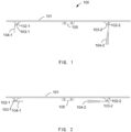
- FIG. 1 shows a structural diagram of one preferred embodiment of a folding module in an unfolded state
- the folding module 100 of the present disclosure basically comprises: a panel 101, a support block 102, a hinge 103 and a support member 104.
- the panel 101 is a solar photovoltaic module having a front side and a backside.
- the front side of the panel 101 is the light-receiving side. Since the present disclosure employs a support structure which are completely different from those of prior art, the panel 101 of the present disclosure can be made to be a frameless panel to save manufacturing cost.
- two support blocks 102-1 and 102-2 are provided on the backside of the panel 101, and are close, respectively, to the two sides of the panel 101 in the longitudinal direction.
- the first and second support blocks 102-1 and 102-2 may be secured on the backside of the panel 101 via adhesive materials such as double-sided tapes, silicone, tapes and silicone, or may be secured on the backside of the panel 101 by means of perforating and securing with screws.
- the present disclosure is not limited to use only two support blocks. It will be appreciated by one skilled in the art that any number of support blocks may be applied based on the present disclosure according to practical needs, and the support blocks may be disposed at various locations along the longitudinal direction of the panel. Further, other known manners for securing the support blocks onto the backside of the panel 101 may also be utilized according to particular needs for machining.
- FIGs 5a and 5b illustrate two preferred constructs for a support block, respectively.
- the support block 102 may comprises a flat-plate support block, as shown in Figure 5a .
- a V-shape support block may be utilized, as shown in Figure 5b .
- a first support member 104-1 is connected to the first support block 102-1 via a first hinge 103-1
- a second support member 104-2 is connected to the second support block 102-2 via a second hinge 103-2.
- the hinges 103 and the support blocks 102 may be connected with adhesive tapes or by means of securing with screws.
- the first support member 104-1 and the second support member 104-2 may serve to support the whole module and may serve as windshields, which provides better wind-proof performance for the module. Since it is needed to sustain a large load stress, the support members is designed with sufficient strength. Referring to the embodiments as shown in Figures 1-4 , the support members 104-1 and 104-2 as shown are designed to be triangle-shape.
- the support members with triangle-shape are designed by taking into consideration of plastic shrinking, hollow design and cost saving.
- the support members have a shape of section bar and may be fabricated by extrusion-molding, which provide advantages of high efficiency, low cost, etc..
- the first support member 104-1 and the second support member 104-2 can fold and rotate about the first hinge 103-1 and the second hinge 103-2, respectively.
- the folding module 100 is in a unfolded state in which the support members 104-1 and 104-2 are orthogonal to the panel 101, e.g. being an angle of 90 degree with respect to the panel 101.
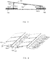
- the folding module 100 is in a folded state in which the support members 104-1 and 104-2 are in horizontal state with respect to the panel 101, e.g. at an angle of 0 degree with respect to the panel 101.
- the folded state is quite suitable for packing and shipping and thereby saving space and cost.
- the folding module may be switched to unfolded state for mounting such that the folding module as a whole is adjusted to an appropriate tilt angle.
- the length of the first support member 104-1 and the second support member 104-2 are adjustable.
- the first support member 104-1 and the second support member 104-2 may comprise retractable support members with adjustable length.
- the first support member 104-1 and the second support member 104-2 may be constructed as a structure having multiple segments with each segment capable of a 90 degree bending with respect to each other, so as to perform height adjustment.
- the present disclosure may apply a structure in which the tilt angle of the first support member 104-1 and the second support member 104-2 with respect to the panel or the mounting surface (such as the ground or the roof, and the likes) can be designated and sustained.
- Other structures known in the art may also be used to achieve a similar tilt angle adjustment.
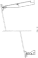
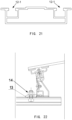
- Figure 7 shows another preferred example structure for the support members.
- the support member 104 may be constituted of a back-shaped member 108 and a support bar 109.
- One end of the back-shaped member 108 is directly connected to the bottom of the support block 102, and one end of the support bar 109 is connected to the back-shaped member 108 at a joint point, such that the joint point, the other end of the support bar 109 and the other end of the back-shaped member 108 constitute a triangle support structure, thereby achieving a effective high strength for the front and rear support members.
- the support bar 109 may further rotate about the joint point, for adjusting the height of the whole support member 104.
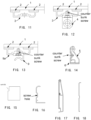
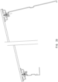
- Figure 3 shows a mounting example for the folding module, according to the present disclosure.
- Figure 4 shows a schematic view of overall mounting scenario for the folding module, according to the present disclosure.
- the first support member 104-1 and the second support member 104-2 are unfolded and rotated to an unfolded state with an angle of 90 degree with respect to the mounting surface (e.g. the ground).
- the mounting surface e.g. the ground
- a securing strip is designed throughout the module.
- two fixing strips 106 go through the first support member 104-1 and the second support member 104-2 respectively, such that the whole folding module is secured.
- the fixing strip 106 goes through the rear support member of a previous module and the front support member of a latter module, with a cover slab 107 in the middle for enhancing the structure.
- the rotation of the hinge and the front and rear support members may be substantially limited by the fixing strip 106.
- the whole folding module structure becomes more robust due to mutual connection among the individual modules.
- FIG 6 shows an example of the structure of the cover slab.
- the cover slab 107 is a simple extrusion member, and is constructed as a bump structure surrounded with wings.
- the bump structure may be conveniently mated with the front and rear fixing strips 106, and the weight of the ballasts at the left and right sides thereof may be adjusted according to the on site wind speed.
- the length of the first support member 104-1 may be set to be larger than the length of the second support member 104-2, such that a desired tilt angle is formed between the panel 101 and the mounting surface (e.g. the ground).
- the first support member 104-1 and the second support member 104-2 may be folded and rotated to a folded state in parallel with the panel 101 (referring to Fig.2 ). Hence, in this folded state, the volume of the whole folding module 100 will be minimized for improved efficiency of packing and shipping.
- the folding module 100 may further comprise a junction box 105 disposed on the backside of the panel 101.
- Figs. 8-25 a further aspect of the present disclosure is illustrated with reference to Figs. 8-25 .
- a skilled person in the art would understand that the following descriptions with reference to Figs. 8-25 are not limited to a single embodiment, and may be subject to any of combination, modification, adaption and adjustment according to practical situation in the field or design requirements, so as to achieve other alternative implementations.
- the various implementations as described according to Figs. 8-25 may be used in combination with the various implementations as described according to Figs. 1-7 , which is also within the sprit and substance embraced by the present disclosure and the claims thereof.
- Fig. 8 shows a backside view of a frameless photovoltaic module system according to an aspect of the present invention.
- Figure 9 shows a cross-sectional view of the front and rear brackets taken along the section line 1-1 in the rear view as shown in Figure 8 , according to an aspect of the present disclosure.
- Figure 10 shows a cross-sectional view of the hook member taken along the section line 2-2 in the rear view as shown in Figure 8 , according to an aspect of the present disclosure.
- the frameless photovoltaic system comprises: a frameless photovoltaic module 1, an adhesive structural tape 2, a backside securing block connector member 3, a securing block 4, a front bracket 5, a front cross-coupling beam 6, a rear bracket 7, a rear wind shield 8, a hook member 9, a backside hook connector member 9a, a liner pad 10, a cable clip 11, a bottom connector member (also referred to as keel frame) (not shown), a securing cover slab 13 (not shown).
- the photovoltaic module 1 uses a frameless design.
- the junction box (as shown in the left of the figure) on the backside of the module 1 provides both a long cable and a short cable, for facilitating mounting work.
- the cables are secured on the backside of the module 1 with a cable clip 11.
- the cable clip 11 is attached onto the backside of the module 1 by bonding or the like.
- the module 1 is attached to the front bracket 5 (exemplarily shown on the top of the module 1 in Fig. 8 ) and the rear bracket 7 (exemplarily shown on the bottom of the module 1 in Fig. 8 ).
- a backside securing block connector member 3 and a backside hook connector member 9a are attached at attaching positions on one side of the module 1 corresponding to the front bracket 5.
- the two connector members may be attached to the module 1 by means of bonding or the like with an adhesive material made of structural adhesive tape 2 or structural silicone, wherein the adhesive material is required to have weather resistance and adhesive properties, such that the static and dynamic load capacity thereof is sufficient for overall stability.
- a backside securing block connector member 3 and a backside hook connector member 9a are also attached to the opposite side (the side opposing to the side attached with the front bracket 5) of the module 1 at attaching positions corresponding to the rear bracket 7, also by means of bonding (i.e. with structural adhesive tapes 2) or the like.
- a liner pad 10 is additionally disposed at the positions where the backside of the module 1 contacts with the rear bracket 7, for preventing the rear bracket 7 from impacting the backside of the module 1 during shipping and mounting.
- Figure 11 shows a diagram of the backside securing block connector member 3 bonded with the module 1, according to an aspect of the present disclosure.
- Figure 12 shows a diagram of the connection structure of the backside securing block connector member 3 bonded with the module 1 and further attached with securing block 4, according to an aspect of the present disclosure.
- Figure 13 further shows a diagram of the connection structure of the backside hook connector member 9a bonded with the module 1 and further attached with a hook member 9, according to an aspect of the present disclosure.
- both of the backside securing block connector member 3 and the backside hook connector member 9a are similarly designed and formed from a section bar by extrusion molding, the cross sections of which are shown in Figures 11 and 13 .
- Adhesive tapes 2 are disposed at predetermined attaching positions where the top wing surfaces of the backside securing block connector member 3 and the backside hook connector member 9a are attached with the module 1.
- the bottom surfaces of the connector members 3 and 9a in contact with the securing block 4 and the hook member 9 are curved to form a shallow groove for defining a mounting location for the securing block or the hook member.
- a screw hole is formed on the bottom surface of the connector members 3 and 9a, corresponding to a connection counter bore of the securing block or hook member.
- the connector members 3 and 9a are attached (such as, by means of bonding) to the module 1 at first, then the securing block 4 is connected to the backside securing block connector member 3 with a countersunk screw, and then the hook member 9 is connected to the backside hook connector member 9a with a countersunk screw.
- the securing block 4 is L-shaped. To ensure the connection strength, the securing block 4 is required to have a thickness. A set of sink holes are disposed on the bottom of the securing block 4. The countersunk screws go through the sink holes, for connecting the securing block 4 with the backside securing block connector member 3 and with the front and rear brackets. As shown in Figure 12 , the securing block 4 has a chamfered side at a side opposing to the sink holes, basically for ensuring smooth rotation of the front and rear brackets.
- the cross section of the hook member 9 is shown in Figure 13 .
- the hook member 9 is basically comprised of a bottom surface and an arc hook portion. This shape is provided for mating with the backside connector member, the top R-shaped member of the front cross-coupling beam 6 (as shown in Figure 10 ) and the top R-shaped member of the rear windshield (as shown in Figures 9 and 10 ).
- a sink hole s disposed on the bottom of the hook member 9. A through which the countersunk screw goes through the sink hole, for securing the backside hook connector member 9a with the front and rear brackets.
- the arc hook portion of the hook member has a concave rounded surface for mating with the top R-shaped member of the front cross-coupling beam 6 and the top R-shaped member of the rear windshield 8.
- a positive wind pressure i.e. a wind pressure blowing to the front side of the module 1 such that the module 1 is pressed towards the support system
- the module 1 is pressed down, causing the backside hook connector member 9a and the hook member 9 to be pressed down and mated with the top R-shaped member of the front cross-coupling beam 6 and the top R-shaped member of the rear windshield 8, thereby transferring the load from the module to its underlying members.
- the bottom arc hook portion of the hook member 9 serves as a rotation pin for limiting the rotation of the front and rear brackets.
- a negative wind pressure i.e. a wind pressure blowing to the rear side of the module 1 such that the module 1 is blow away from the support system
- the bottom arc hook portion may be hooked with the top R-shaped member of the front cross-coupling beam 6 and the top R-shaped member of the rear windshield 8, thereby resisting the negative wind pressure together with the whole support system.
- FIG 14 shows a sectional view of a front bracket assembly, according to an aspect of the present disclosure.
- the front bracket assembly is comprised of the front bracket 5 and the front cross-coupling beam 6, with an R-shaped member formed on the top thereof.
- the top of the front bracket assembly is connected to the securing block 4 with a countersunk screw, while the bottom surface of the front bracket assembly is secured to the bottom connector member (keel frame) 12 (not shown) by a cover slab structure and is at a right angle with respect to the bottom connector member (keel frame) 12.
- a side surface of the front bracket 5 fits the front cross-coupling beam 6.
- the front bracket 5 is a rotating member, which is formed with a cylindrical head and is shaped into an R-shaped member (as viewed from the cross section), and is provided with a rounded hole for facilitating thread machining.
- the side portion of the front bracket is formed to be a slope structure (as seen from the right side of Figure 14 ), to avoiding any potential collision with the backside securing block connector member 3 of the module 1.
- a connection portion of the side portion of the front bracket 5 mating with the front cross-coupling beam 6 (exemplarily shown in the left of the figure) has a groove which couples with the groove at the side surface of the cross-coupling beam 6 (as shown in Figure 16 ).
- a screw hole is provided in the groove such that a connecting bolt head may go through the screw hole to connect with the screw hole in the groove at the side surface of the cross-coupling beam 6, thereby assembling the front bracket 5 with the front cross-coupling beam 6.
- the bottom portion of the front bracket assembly is further provided with a mounting slot for cover slab mounting.
- FIG. 15 shows a schematic view of the rotation limiter notch of the front bracket, according to an aspect of the present disclosure.
- the front bracket assembly is rotated to a predetermined mounting position, the bottom side of the notch contacts with the lower side of the securing block, providing limiting as shown in the left of Fig. 19 . Due to the relatively small height of the front bracket, the notch would not provide any limitation if it is machined to be bigger.
- the module may be rotated in the system, which would be more convenient for system maintenance.
- the front bracket 5 is symmetrically machined. A side of the lower portion of the front bracket 5 adjacent to the front cross-coupling beam 6 is designed to be a corner slot surface above the bottom portion.
- FIG 16 shows a cross-sectional view of the front cross-coupling beam 6 according to one aspect of the present disclosure.
- the front cross-coupling beam is required to have a certain strength and rigidity to serve as a bottom side support bar for the module system.
- the top portion of the front cross-coupling beam is designed to be an arc surface, which may be mated with the hook assembly 9 through a shaft structure, such that the front bracket assembly can rotate smoothly.
- the side surface of the front cross-coupling beam 6 is provided with a groove in which a screw hole is provided. A connecting bolt may go through this screw hole to connected it with a screw hole in the side groove at the side surface of the front bracket 5.
- the groove may accommodate the connecting bolt such that it does not protrude beyond the side plane of the cross-coupling beam 6.
- the corner slot surface of the front bracket 5 is clamped by the lower portion of the cross-coupling beam 6, so as to better connect with the front bracket 5.
- the lower portion basically functions to increase rigidity of the coupling beam. The purpose of the lower portion is to increase the rigid of the beam.
- the end at the other side of the lower portion of the cross-coupling beam 6 fits the lower portion of the front bracket 5, and is machined with a notch and a bolt hole by punching.
- FIG 17 shows a cross-sectional view of the rear bracket assembly according to one aspect of the present disclosure.
- the rear bracket assembly is comprised of a rear bracket 7 and a rear windshield 8, and is formed with an R-shaped member on the top portion thereof. Similar with the front bracket assembly of Figure 14 , the top portion of the rear bracket assembly is connected to the securing block 4 via a countersunk bolt, and the bottom portion thereof is secured to the bottom connector member (keel frame) 12 by a cover slab structure. In the assembly, a side surface of the rear bracket 7 fits the rear cross-coupling beam 8.
- the rear bracket 7 is a rotating member, which is formed with a cylindrical head and is shaped into an R-shaped member (as viewed from the cross section), and is provided with a rounded hole for facilitating thread machining.
- the side portion of the rear bracket is formed to be a slope structure (as seen from the right side of Figure 17 ), to avoiding any potential collision with the backside securing block connector member 3 of the module 1.
- a connection portion of the side portion of the rear bracket 7 mating with the rear windshield 8 (exemplarily shown in the left of the figure) has a groove which couples with the groove at the side surface of the rear windshield 8 (as shown in Figure 18 ).
- a screw hole is provided in the groove such that a connecting bolt head may go through the screw hole to connect with the screw hole in the groove at the side surface of the rear windshield 8, thereby assembling the rear bracket 7 with the rear windshield 8.
- the bottom portion of the rear bracket assembly is further provided with a mounting slot.
- FIG. 15 also shows a schematic view of the rotation limiter notch of the rear bracket, according to one aspect of the present disclosure. As shown in the figure, when the rear bracket 7 is rotated to a predetermined mounting position, the bottom side of the notch contacts with the lower side of the securing block, providing limiting as shown in the right of Fig. 19 .
- the rear bracket 7 is symmetrically machined. A side of the lower portion of the rear bracket 7 adjacent to the rear windshield 8 is designed to be a corner slot surface above the bottom portion.
- FIG 18 shows a cross-sectional view of the rear windshield 8 according to one aspect of the present disclosure.
- the rear windshield 8 mainly servers to shield wind from the rear, so as to prevent the backside of the module 1 from wind load.
- the rear windshield 8 serves as a top side supporting bar for the module, with the top portion thereof designed to be an arc surface to mate with the hook member 9 through a shaft structure, such that the rear bracket assembly can rotate smoothly.
- the side surface of the rear windshield 8 is provided with a groove in which a screw hole is provided.
- a connecting bolt may go through this screw hole to connected it with a screw hole in the side groove at the side surface of the rear bracket 7. Further, the groove may accommodate the connecting bolt such that it does not protrude beyond the side plane of the rear windshield 8.
- the lower portion of the rear windshield 8 is designed to be a clamp structure, which may be clamped with the corner slot surface of the lower portion of the rear bracket 7, so as to better connect with the rear bracket 7.
- the rear windshield 8 is machined to have reverse openings, to provide excellent ventilation for the whole system.
- the rear bracket 7 locates higher than the front bracket 5, so as to have the rear bracket 7 disposed at a right angle with respect to the module 1, such that the stress on the rear bracket is reduced .
- FIG. 19 shows the connection status of the hook member, the rear windshield along with the front cross-coupling beam when the front bracket and rear bracket are unfolded. It will be noted that Figures 19 , 20 do not show a complete module 1 but only the connection sections of the module 1 with the front and rear brackets, with the middle portions of the module 1 omitted.
- Figure 21 shows a cross-sectional view of the bottom connector member (keel frame) according to one aspect of the present disclosure.
- the left and right sides of the top portion of the bottom connector member (keel frame) 12 are respectively provided with a bolt head groove 12-1 for inserting a cover slab.
- a set of reverse ripples are provided at the portion of the top surface jointed with the front/rear bracket assembly.
- An extrusion portion is provided at the middle of the top surface of the bottom connector member (keel) 12 to provide a certain gap between the modules.
- the width of the middle extrusion portion may be 28 mm.
- the cavity at the middle of the bottom connector member (keel frame) is relatively large. Since the connection length of the keel frame at the middle is relatively short, the front and rear cabling of module 1 may routed through this.
- FIG 25 shows a flow chart of on site mounting work for the system, according to one aspect of the present disclosure.
- the bottom connector member (keel frame) 12 is deployed at first.
- the front bracket assembly and the rear bracket assembly of module 1 are unfolded (i.e. the securing bolt is released), and the front/rear bracket assemblies are rotated to a mounting position and secured again, as shown in Figures 19-20 .
- the module 1 that has been configured to the mounting position is moved onto the bottom connector member (keel frame) 12.
- step 2507 all members are deposited and checked, then a securing cover slab 13 is inserted to secure the front bracket assembly and the rear bracket assembly.
- a portion of the securing cover slab 13 is clamped into the mounting slot provided at the lower portions of the front bracket assembly and the rear bracket assembly.
- the cover slab bolt 14 is inserted into the securing cover slab 13, and a portion of the cover slab bolt 14 is accommodated and secured in the cover slab bolt head slot 12-1 of the bottom connector member (keel frame) 12, thereby securing the module system on the bottom connector member (keel frame) 12.
- This mounting work is simple and particularly feasible for mounting on site.
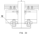
- Figures 22 , 23 show the detailed mounting structure.
- cover slab bolt 14 may be pre-disposed in the cover slab bolt head slot 12-1 of the bottom connector member (keel) 12, thereby for fast and easy mounting.
- all cables are deployed prior to securing the cover slab bolt and the securing cover slab. After connection, the rest of cables may be positioned in the inner side of the bottom connector member (keel frame) 12.
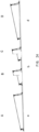
- Figure 24 shows a schematic view of a longitudinal cross-section of the photovoltaic matrix system, according to one aspect of the present disclosure. It will be noted that Figure 24 does not show a complete module 1, but only the connection portions of the module 1, the front and rear brackets and the bottom connector member (keel frame), with the middle portions of the module 1 omitted from the figure. As shown in Figure 24 , a plurality of modules 1 are arranged into rows. Figure 24 only shows a module system A in the beginning position and a module system D in the last position, together with a module system B in the second position and a module system C in the second to last position. It will be appreciated that there may be multiple intermediate module systems between the module system B and the module system C, as desired by the practical needs.
- the bottom connector members (keel frame) a in the beginning position and the bottom connector members (keel frame) d in the last position are connected, respectively, to the front and rear assemblies of the module system A in the beginning position and the module system D in the last position.
- the front bracket assembly of the module system B in the second position is connected to the bottom connector member (keel frame) a in the very beginning position, and the rear bracket assembly thereof is connected to the bottom connector member (keel frame) b in the second position.
- the front bracket assembly of the module systems C in the second to last position is connected to the bottom connector member (keel frame) c (not shown) in the second to last position, and the rear bracket assembly thereof is connected to the bottom connector member (keel frame) d in the last position.
- the rear bracket assembly thereof is connected to the bottom connector member (keel frame) d in the last position.
- the keel frame in the second position to the keel frame in the n-1 position are connected to the rear bracket assembly of the previous neighboring module system and the front bracket assembly of the subsequent neighboring module system. Accordingly, the whole solar photovoltaic square array system is formed.
Landscapes
- Engineering & Computer Science (AREA)
- Architecture (AREA)
- Structural Engineering (AREA)
- Civil Engineering (AREA)
- Chemical & Material Sciences (AREA)
- Thermal Sciences (AREA)
- Physics & Mathematics (AREA)
- Combustion & Propulsion (AREA)
- Mechanical Engineering (AREA)
- General Engineering & Computer Science (AREA)
- Sustainable Energy (AREA)
- Sustainable Development (AREA)
- Life Sciences & Earth Sciences (AREA)
- Photovoltaic Devices (AREA)
- Roof Covering Using Slabs Or Stiff Sheets (AREA)
Claims (12)
- Structure de montage de modules photovoltaïques, comprenant :
une pluralité de modules photovoltaïques (1), chacun d'entre eux comprenant un panneau comportant un côté avant, qui est un côté de réception de la lumière, et :un premier élément connecteur à bloc de fixation côté arrière (3) et un premier élément connecteur à crochet côté arrière (9a), tous deux fixés à une première extrémité du côté arrière du panneau de chaque module photovoltaïque ;un ensemble de support avant auquel le premier élément connecteur à bloc de fixation côté arrière (3) et le premier élément connecteur à crochet côté arrière (9a) sont de plus fixés ;un deuxième élément connecteur à bloc de fixation côté arrière (3) et un deuxième élément connecteur à crochet côté arrière (9a), tous deux fixés à une deuxième extrémité du côté arrière du panneau de chaque module photovoltaïque ;un ensemble de support arrière (7) auquel le deuxième élément connecteur à bloc de fixation côté arrière (3) et le deuxième élément connecteur à crochet côté arrière (9a) sont de plus fixés ;dans laquelle l'ensemble de support avant est relié au premier élément connecteur à bloc de fixation côté arrière (3) et au premier élément connecteur à crochet côté arrière (9a) par l'intermédiaire d'une première charnière de manière à pouvoir tourner librement autour du premier élément connecteur à bloc de fixation côté arrière (3) et du premier élément connecteur à crochet arrière (9a), et l'ensemble de support arrière (7) est relié au deuxième élément connecteur à bloc de fixation côté arrière (3) et au deuxième élément connecteur à crochet côté arrière (9a) par l'intermédiaire d'une deuxième charnière de manière à pouvoir tourner librement autour du deuxième élément connecteur à bloc de fixation côté arrière (3) et du deuxième élément connecteur à crochet côté arrière (9a) ;caractérisée en ce que l'ensemble de support avant comprend un support avant (5) et un profilé d'accouplement transversal avant (6), dans laquelle le support avant (5) est formé avec une tête cylindrique et est façonné en un élément en forme de « R » tel que vu à partir d'une section transversale ;dans laquelle une surface latérale du support avant (5) s'adapte au profilé d'accouplement transversal avant (6) ;dans laquelle le profilé d'accouplement transversal avant (6) sert de barre de support latérale de fond pour le module ;et en ce que la structure de montage photovoltaïque comprend de plus un premier et un deuxième éléments à crochet (9) comprenant chacun une surface de fond et une partie à crochet arqué ;dans laquelle le premier élément à crochet (9) est relié au premier élément connecteur à crochet côté arrière (9a) avec une vis à tête fraisée et le deuxième élément à crochet (9) est relié au deuxième élément connecteur à crochet côté arrière (9a) avec une vis à tête fraisée ;dans laquelle la partie à crochet arqué du premier élément à crochet comporte une surface arrondie concave pour se conjuguer à l'élément sommital en forme de « R » du profilé d'accouplement transversal avant (6) ;et en ce que le sommet de l'ensemble de support avant est reliée à un bloc de fixation (4) avec une vis à tête fraisée, tandis que la surface de fond de l'ensemble de support avant est fixée à un élément connecteur de fond (12) par une structure de dalle de recouvrement (13) et est à angle droit par rapport à l'élément connecteur de fond (12). - Structure de montage de modules photovoltaïques selon la revendication 1, dans laquelle la pluralité de modules photovoltaïques (1) est disposée en rangées, et les modules sont reliés les uns aux autres par l'élément connecteur de fond (12), de manière à constituer un système de matrice de modules photovoltaïques ; dans laquelle l'ensemble de support avant (5) et l'ensemble de support arrière (7) du module photovoltaïque dans la première position sont fixés à l'élément connecteur de fond (12) dans la première position, l'ensemble de support avant (5) et l'ensemble de support arrière (7) du module photovoltaïque dans la dernière position sont fixés à l'élément connecteur de fond (12) dans la dernière position, et l'ensemble de support avant (5) de chacun des modules photovoltaïques entre le module photovoltaïque dans la première position et le module photovoltaïque dans la dernière position est fixé à l'élément connecteur de fond (12) dans la position voisine précédente et l'ensemble de support arrière (7) de chacun des modules photovoltaïques entre le module photovoltaïque dans la première position et le module photovoltaïque dans la dernière position est fixé à l'élément connecteur de fond (12) dans la position voisine suivante.
- Structure de montage de modules photovoltaïques selon la revendication 2, dans laquelle le premier élément connecteur de fixation côté arrière, le premier élément connecteur à crochet côté arrière, le deuxième élément connecteur à bloc de fixation côté arrière (3) et le deuxième élément connecteur à crochet côté arrière (9a) sont fixés au module photovoltaïque en utilisant une bande structurelle adhésive (2), la bande structurelle adhésive étant disposée sur une partie de fixation prédéterminée des surfaces alaires sommitales des premier et deuxième éléments connecteurs à crochet côté arrière (9a) ainsi que des premier et deuxième éléments connecteurs de fixation côté arrière (3).
- Structure de montage de modules photovoltaïques selon la revendication 3, dans laquelle les premier et deuxième éléments connecteurs de fixation côté arrière (3) comportent une structure similaire à celle des premier et deuxième éléments connecteurs à crochet côté arrière (9a), les deux étant formés à partir d'une barre de section par moulage par extrusion, et dans laquelle les premier et deuxième éléments connecteurs de fixation (3) sont fixés, respectivement, à l'ensemble de support avant (5) et à l'ensemble de support arrière (7), par l'intermédiaire d'un bloc de fixation (4), les premier et deuxième éléments connecteurs à crochet côté arrière (9a) sont fixés à l'ensemble de support avant et à l'ensemble de support arrière par l'intermédiaire de l'élément en forme de crochet (9), et
dans laquelle les côtés de fond des premier et deuxième éléments connecteurs de fixation et des premier et deuxième éléments connecteurs à crochet côté arrière (9a) en contact avec le bloc de fixation (4) ou l'élément en forme de crochet (9) sont incurvés avec une rainure peu profonde pour fournir une limitation de position pour le bloc de fixation ou l'élément en forme de crochet pendant le montage, les côtés de fond étant de plus pourvus d'un trou de vis correspondant à un alésage à tête fraisé du bloc de fixation (4) ou de l'élément en forme de crochet (9). - Structure de montage de modules photovoltaïques selon la revendication 4, dans laquelle le bloc de fixation (4) a une forme en « L » et une épaisseur pour assurer une force de raccordement, un côté de fond du bloc de fixation (4) est pourvu d'un trou d'enfoncement pour le raccordement avec les premier et deuxième éléments connecteurs de fixation (3), et dans laquelle le trou d'enfoncement est prévu pour permettre le passage d'un boulon à tête fraisée, et le bloc de fixation (4) comporte un côté chanfreiné en correspondance d'un côté opposé au trou d'enfoncement.
- Structure de montage de modules photovoltaïques selon la revendication 5, dans laquelle l'élément en forme de crochet est constitué d'un côté de fond et d'une partie en forme de crochet arqué, un trou d'enfoncement est disposé sur le côté de fond de l'élément en forme de crochet pour le raccordement aux premier et deuxième éléments connecteurs à crochet côté arrière (9a), le trou d'enfoncement étant prévu pour permettre le passage d'un boulon à tête fraisée, la partie en forme de crochet arqué possède une surface arrondie concave pour se conjuguer à un élément sommital en forme de « R » de l'ensemble de support avant et un élément sommital en forme de « R » de l'ensemble de support arrière, de sorte que lorsque le module photovoltaïque est soumis à une pression du vent positive et est pressé vers le bas, la surface arrondie concave est conjuguée aux éléments sommitaux en forme de « R », transférant ainsi la charge du module aux éléments sous-jacents par étapes, et lorsque le module photovoltaïque est soumis à un vent négatif et est emporté de la structure de montage, la partie en forme de crochet arqué forme un accrochage avec les éléments sommitaux en forme de « R » de l'ensemble de support avant et de l'ensemble de support arrière, luttant ainsi contre la pression du vent négative avec l'ensemble de la structure de montage, et dans laquelle la partie en forme de crochet arqué sert de plus de broche de rotation pour limiter la rotation des supports avant et arrière.
- Structure de montage de modules photovoltaïques selon la revendication 6, dans laquelle l'ensemble de support avant est composé d'un support avant (5) et d'un profilé d'accouplement transversal avant (6), et est formé avec un élément en forme de « R » au sommet de celui-ci, l'ensemble de support avant est relié au bloc de fixation (4) par l'intermédiaire d'un boulon à tête fraisée et est conjugué à l'élément en forme de crochet avec l'élément en forme de « R », la partie de fond de l'ensemble de support avant est fixée à l'élément connecteur de fond (12) par une structure de dalle de recouvrement et est disposée à angle droit par rapport à l'élément connecteur de fond, dans laquelle la partie latérale de l'ensemble de support avant est formée pour être une structure en pente pour éviter toute collision potentielle avec l'élément connecteur de fixation, la surface latérale du support avant s'adapte de plus au profilé d'accouplement transversal, et une partie latérale du support avant et une partie latérale du profilé d'accouplement transversal qui sont reliées l'une à l'autre comportent toutes deux une rainure, les rainures s'accouplent l'une à l'autre et comportent toutes deux un trou de vis, le support avant est assemblé au profilé d'accouplement transversal par l'intermédiaire du trou de vis avec une tête de boulon de raccordement, la partie de fond de l'ensemble de support avant est pourvue d'une fente de montage pour se conjuguer à une dalle de recouvrement, et la partie sommitale du support avant est usinée avec une encoche de limitation de rotation, de sorte que lorsque l'ensemble de support avant est tourné vers une position de montage, le côté de fond de l'encoche entre en contact avec le côté de fond du bloc de fixation (4) pour fournir une limitation de position.
- Structure de montage de modules photovoltaïques selon la revendication 7, dans laquelle le sommet du profilé d'accouplement transversal avant est conçu avec une surface arquée de manière à se conjuguer à l'élément en forme de crochet par l'intermédiaire d'une structure en arbre pour faciliter une rotation en douceur de l'ensemble de support avant, et la tête de boulon est reçue par une rainure sur la surface latérale du profilé d'accouplement transversal de sorte qu'elle ne dépasse pas au-delà du plan latéral du profilé d'accouplement transversal, un côté de la partie inférieure du support avant adjacent au profilé d'accouplement transversal est conçu pour être une surface de fente d'angle au-dessus de la partie de fond de sorte qu'un côté de la partie inférieure du profilé d'accouplement transversal se serre avec la surface de fente d'angle, améliorant ainsi le raccordement au support avant, et une extrémité sur l'autre côté de la partie inférieure du profilé d'accouplement transversal s'adapte de plus à la partie inférieure du support avant et est usinée avec une encoche et est perforée avec un trou de vis.
- Structure de montage de modules photovoltaïques selon la revendication 8, dans laquelle l'ensemble de support arrière est composé d'un support arrière (7) et d'un pare-brise arrière (8), et est formé avec un élément en forme de « R » au sommet, la partie sommitale de l'ensemble de support arrière est reliée au bloc de fixation (4) par l'intermédiaire d'un boulon à tête fraisée, et la partie inférieure de celui-ci est fixée à l'élément connecteur de fond (12) par une structure de dalle de recouvrement, dans laquelle le support arrière est aussi un élément rotatif, et est formé avec une tête cylindrique et est façonné en forme de « R », et est pourvu d'un trou arrondi pour faciliter l'usinage du filetage, la partie latérale de l'ensemble de support arrière est formée pour être une structure en pente pour éviter toute collision potentielle avec l'élément connecteur de fixation, la surface latérale du support arrière s'adapte de plus au pare-brise arrière, et une partie latérale du support arrière et une partie latérale du pare-brise arrière qui sont reliées l'une à l'autre comportent toutes deux une rainure, les rainures s'accouplent l'une à l'autre et comportent toutes deux un trou de vis, le support arrière est assemblé avec le pare-brise arrière par l'intermédiaire du trou de vis à tête de boulon de raccordement, la partie inférieure de l'ensemble de support arrière est pourvue d'une fente de montage, et la partie sommitale du support arrière est usinée avec une encoche de limitation de rotation, de sorte que lorsque l'ensemble de support arrière est tourné vers une position de montage, le côté de fond de l'encoche entre en contact avec le côté de fond du bloc de fixation (4) pour fournir une limitation de position.
- Structure de montage de modules photovoltaïques selon la revendication 9, dans laquelle l'une des fonctions du pare-brise arrière est de faire écran au vent par l'arrière pour empêcher le côté arrière du photovoltaïque d'être soumis à la charge du vent, tandis que le sommet du pare-brise arrière est conçu pour être une surface arquée pour se conjuguer à l'élément en forme de crochet par l'intermédiaire d'une structure en arbre de sorte que l'ensemble de support arrière puisse tourner en douceur, en outre, la rainure en correspondance de la surface latérale du pare-brise arrière peut recevoir la tête de boulon de raccordement de sorte qu'elle ne dépasse pas au-delà du plan latéral du pare-brise, en outre, un côté de la partie inférieure du support arrière adjacent au pare-brise arrière est conçu pour être une surface de fente d'angle au-dessus de la partie de fond, et la partie inférieure du pare-brise arrière est formée avec une structure de serrage pour se serrer avec la surface de fente d'angle du support arrière de sorte qu'elle se raccorde mieux au support arrière, le pare-brise arrière est usiné pour avoir des ouvertures inversées pour fournir une excellente ventilation à l'ensemble de la structure de montage de modules photovoltaïques ; dans laquelle le boulon à tête fraisée du bloc de fixation (4) peut être libéré de telle sorte que l'ensemble de support avant et l'ensemble de support arrière peuvent être tournés en douceur, et lorsque l'ensemble de support avant et l'ensemble de support arrière sont tournés vers une position de montage, le boulon à tête fraisée est à nouveau fixé pour le montage,
dans laquelle les côtés gauche et droit de la partie sommitale de l'élément connecteur de fond (12) sont respectivement disposés avec une rainure de tête de boulon (12-1) pour une dalle de recouvrement, et un ensemble d'ondulations inversées sont prévues en correspondance de la partie de la surface sommitale jointe à l'ensemble de support avant et à l'ensemble de support arrière, en outre, une partie d'extrusion est prévue au milieu de la surface sommitale de l'élément connecteur de fond, de manière à fournir un certain espace entre les modules. - Procédé de montage de la structure de montage de modules photovoltaïques selon les revendications 1-10, comprenant :déployer l'élément connecteur de fond (12) ;déplier l'ensemble de support avant et l'ensemble de support arrière du module photovoltaïque (1) et faire tourner l'ensemble de support avant et l'ensemble de support arrière vers une position de montage, puis fixer à nouveau l'ensemble de support avant et l'ensemble de support arrière ;déplacer le module photovoltaïque qui a été configuré dans la position de montage sur l'élément connecteur de fond ;après avoir vérifié tous les éléments, disposer une dalle de recouvrement (13) pour fixer l'ensemble de support avant et l'ensemble de support arrière ;insérer un boulon de dalle de recouvrement (14) dans la dalle de recouvrement de fixation et fixer le boulon de dalle de recouvrement, fixant ainsi le module photovoltaïque sur l'élément connecteur de fond.
- Procédé selon la revendication 11, dans lequel la disposition de la dalle de recouvrement comprend :serrer une partie de la dalle de recouvrement de fixation dans une fente de montage prévue en correspondance des parties inférieures de l'ensemble de support avant et de l'ensemble de support arrière, etpréparer une bande de revêtement en bois avant le montage, et prédisposer un boulon de dalle de recouvrement dans une fente de tête de boulon de dalle de recouvrement de l'élément connecteur de fond pour un montage rapide et facile, et déployer tous les câbles avant la fixation du boulon de dalle de recouvrement et de la dalle de recouvrement de fixation, et placer le reste des câbles après raccordement dans le côté intérieur de l'élément connecteur de fond.
Applications Claiming Priority (3)
| Application Number | Priority Date | Filing Date | Title |
|---|---|---|---|
| CN201210134804.1A CN102683444B (zh) | 2012-05-03 | 2012-05-03 | 折叠式组件 |
| CN201210369274.9A CN102881743B (zh) | 2012-09-28 | 2012-09-28 | 一种光伏组件安装结构及其安装方法 |
| PCT/CN2012/083316 WO2013163866A1 (fr) | 2012-05-03 | 2012-10-22 | Structure de montage d'ensemble photovoltaïque à charnière et son procédé de montage |
Publications (3)
| Publication Number | Publication Date |
|---|---|
| EP2884545A1 EP2884545A1 (fr) | 2015-06-17 |
| EP2884545A4 EP2884545A4 (fr) | 2016-01-27 |
| EP2884545B1 true EP2884545B1 (fr) | 2023-03-29 |
Family
ID=49514197
Family Applications (1)
| Application Number | Title | Priority Date | Filing Date |
|---|---|---|---|
| EP12875799.4A Active EP2884545B1 (fr) | 2012-05-03 | 2012-10-22 | Structure de montage d'ensemble photovoltaïque à charnière et son procédé de montage |
Country Status (6)
| Country | Link |
|---|---|
| US (1) | US9559633B2 (fr) |
| EP (1) | EP2884545B1 (fr) |
| JP (1) | JP6157594B2 (fr) |
| ES (1) | ES2950476T3 (fr) |
| IN (1) | IN2014DN10302A (fr) |
| WO (1) | WO2013163866A1 (fr) |
Families Citing this family (12)
| Publication number | Priority date | Publication date | Assignee | Title |
|---|---|---|---|---|
| JP6573485B2 (ja) * | 2015-06-01 | 2019-09-11 | 旭化成ホームズ株式会社 | 固定部材 |
| CN107453699B (zh) * | 2017-08-28 | 2024-01-23 | 江西清华泰豪三波电机有限公司 | 一种光伏组件及光伏装置 |
| CN108155860A (zh) * | 2017-12-30 | 2018-06-12 | 安徽伙伴电气有限公司 | 一种用于太阳能光伏组件的可调式随动底盘 |
| CN108540054B (zh) * | 2018-04-19 | 2020-09-08 | 国家电投集团江西水电检修安装工程有限公司 | 一种机动型大功率光伏发电装置 |
| CN110120780A (zh) * | 2019-05-30 | 2019-08-13 | 中国人民解放军32181部队 | 一种多级抽拉式光伏框架组件 |
| CN113595489A (zh) * | 2021-07-08 | 2021-11-02 | 湖南大海诚创新能源科技有限公司 | 一种可升降式光伏折叠升降系统 |
| DE102021124625A1 (de) | 2021-08-11 | 2023-02-16 | Mounting Solutions PV Systems GmbH | Photovoltaik-Montagesystem |
| CN113954602B (zh) * | 2021-09-01 | 2023-07-04 | 江苏九州电器有限公司 | 一种便于安装的车厢用电加热器 |
| IT202200005417A1 (it) * | 2022-03-18 | 2023-09-18 | Conatct Italia srl | Sistema di montaggio concatenato di file di pannelli fotovoltaici |
| CN114785264B (zh) * | 2022-05-09 | 2023-02-07 | 宁波欧达光电有限公司 | 一种能够层叠收拢的光伏单元以及光伏组件 |
| CN116314411B (zh) * | 2023-05-17 | 2023-08-01 | 赫里欧新能源有限公司 | 一种折叠式光伏板封装背板 |
| BE1030180B1 (de) * | 2023-05-25 | 2024-07-01 | Shanghai Chiko Solar Tech | Verbindungsvorrichtung für eine photovoltaische Solarhalterung und photovoltaische Solarhalterung |
Citations (1)
| Publication number | Priority date | Publication date | Assignee | Title |
|---|---|---|---|---|
| JP2012054420A (ja) * | 2010-09-01 | 2012-03-15 | Ntt Facilities Inc | 太陽電池パネル架台、及び太陽電池装置 |
Family Cites Families (32)
| Publication number | Priority date | Publication date | Assignee | Title |
|---|---|---|---|---|
| US4421943A (en) * | 1982-02-19 | 1983-12-20 | Cities Service Company | Collapsible mobile solar energy power source |
| US6046399A (en) * | 1997-01-13 | 2000-04-04 | Kapner; Mark | Roofing panels with integral brackets for accepting inclined solar panels |
| NL1017567C2 (nl) * | 2001-03-12 | 2002-09-20 | Jazo Zevenaar B V | Houder voor een fotovolta´sch paneel. |
| JP2003234492A (ja) * | 2002-02-12 | 2003-08-22 | Fuchimoto Ritsuko | 太陽電池モジュールの取付具及び工法 |
| JP2006278738A (ja) * | 2005-03-29 | 2006-10-12 | Kyocera Corp | 太陽光発電装置 |
| WO2006121013A1 (fr) * | 2005-05-11 | 2006-11-16 | Kaneka Corporation | Module de cellules solaires, et surface d’installation de cellules solaires |
| JP3118743U (ja) * | 2005-11-22 | 2006-02-02 | 稔 上原 | 陸屋根用架台 |
| US7814899B1 (en) * | 2006-07-04 | 2010-10-19 | Jonathan Port | Solar panel mounting systems |
| US7857269B2 (en) * | 2006-11-29 | 2010-12-28 | Pvt Solar, Inc. | Mounting assembly for arrays and other surface-mounted equipment |
| FR2922365B1 (fr) * | 2007-10-16 | 2009-12-18 | Avancis Gmbh & Co Kg | Perfectionnements apportes a des elements capables de collecter de la lumiere. |
| DE102007060023A1 (de) * | 2007-12-13 | 2009-06-18 | Yamaichi Electronics Deutschland Gmbh | Anschlußdose, System, Verfahren und Verwendung |
| JP5451989B2 (ja) * | 2008-06-10 | 2014-03-26 | 三菱電機株式会社 | 太陽電池架台装置 |
| TWI529358B (zh) * | 2008-07-14 | 2016-04-11 | Gehrlicher Solar Ag | 用於寬面太陽能模組之固定裝置以及太陽能模組 |
| ES1068787Y (es) * | 2008-09-26 | 2009-03-01 | Solid Enginyeria S L | Estructura de soporte de paneles solares |
| CN201369334Y (zh) | 2009-01-15 | 2009-12-23 | 李毅 | 非晶硅太阳能电池组件 |
| CN101847665A (zh) | 2009-03-26 | 2010-09-29 | 秦超 | 可调节式太阳能支架 |
| US8085565B2 (en) | 2009-04-08 | 2011-12-27 | Lear Corporation | Vehicle inverter for powering consumer electronic devices |
| US20100288337A1 (en) * | 2009-05-13 | 2010-11-18 | Nathan Rizzo | Solar panel assembly |
| WO2010133688A2 (fr) * | 2009-05-20 | 2010-11-25 | Csem Centre Suisse D'electronique Et De Microtechnique Sa Recherche Et Développement | Ilôts solaires pouvant couvrir les besoins d'un ménage |
| FR2950956B1 (fr) * | 2009-10-07 | 2012-11-23 | Dani Alu | Dispositif de lestage de panneau solaire |
| FR2953912B1 (fr) | 2009-12-10 | 2014-02-14 | Asten Assistance Services Traitements Environnement Nucleaire | Systeme de support de panneaux photovoltaiques et procede de support correspondant |
| CN201820766U (zh) * | 2010-06-21 | 2011-05-04 | 鸿富锦精密工业(深圳)有限公司 | 太阳能光电板安装支架 |
| DE102010017705A1 (de) | 2010-07-02 | 2012-01-05 | Patrik Diwald | Montagevorrichtung zur Anordnung von Solarmodulen |
| CN201773843U (zh) | 2010-08-02 | 2011-03-23 | 无锡尚德太阳能电力有限公司 | 太阳电池组件边框以及带有该边框的太阳电池组件 |
| CA2808649A1 (fr) * | 2010-09-03 | 2012-03-08 | Solar Liberty Energy Systems, Inc. | Ensemble rayonnage de panneau solaire |
| CN201904353U (zh) * | 2010-11-30 | 2011-07-20 | 聂恒辉 | 一种带有支架的太阳能电池 |
| NL2005826C2 (en) * | 2010-12-07 | 2012-06-08 | Johannes Lieuwe Wever | Frame system for fixing panels at an angle on the ground. |
| CN201985126U (zh) | 2011-03-26 | 2011-09-21 | 杭州帷盛太阳能科技有限公司 | 太阳能光伏板安装支架 |
| CN202103062U (zh) | 2011-05-06 | 2012-01-04 | 天津天润成能源技术研发有限公司 | 一种光伏系统专用的双向可调支架 |
| US8590223B2 (en) * | 2011-08-29 | 2013-11-26 | A. Raymond Et Cie | Solar panel assembly attachment apparatus |
| CN102315331B (zh) | 2011-10-08 | 2012-12-12 | 保定天威集团有限公司 | 一种轻量化薄膜太阳能电池组件及其制作方法 |
| CN102683444B (zh) * | 2012-05-03 | 2016-04-06 | 常州天合光能有限公司 | 折叠式组件 |
-
2012
- 2012-10-22 JP JP2015509283A patent/JP6157594B2/ja active Active
- 2012-10-22 IN IN10302DEN2014 patent/IN2014DN10302A/en unknown
- 2012-10-22 EP EP12875799.4A patent/EP2884545B1/fr active Active
- 2012-10-22 WO PCT/CN2012/083316 patent/WO2013163866A1/fr active Application Filing
- 2012-10-22 ES ES12875799T patent/ES2950476T3/es active Active
-
2014
- 2014-11-03 US US14/531,665 patent/US9559633B2/en active Active
Patent Citations (1)
| Publication number | Priority date | Publication date | Assignee | Title |
|---|---|---|---|---|
| JP2012054420A (ja) * | 2010-09-01 | 2012-03-15 | Ntt Facilities Inc | 太陽電池パネル架台、及び太陽電池装置 |
Also Published As
| Publication number | Publication date |
|---|---|
| ES2950476T3 (es) | 2023-10-10 |
| JP2015521457A (ja) | 2015-07-27 |
| IN2014DN10302A (fr) | 2015-08-07 |
| JP6157594B2 (ja) | 2017-07-05 |
| EP2884545A1 (fr) | 2015-06-17 |
| US9559633B2 (en) | 2017-01-31 |
| EP2884545A4 (fr) | 2016-01-27 |
| WO2013163866A1 (fr) | 2013-11-07 |
| US20150129014A1 (en) | 2015-05-14 |
Similar Documents
| Publication | Publication Date | Title |
|---|---|---|
| EP2884545B1 (fr) | Structure de montage d'ensemble photovoltaïque à charnière et son procédé de montage | |
| US9171980B2 (en) | Photovoltaic apparatus, photovoltaic module and fastener thereof | |
| US7726301B2 (en) | Solar energy base-body structure | |
| US20140360558A1 (en) | Pivot Framing System For Dual Glass Photovoltaic Modules | |
| JPWO2011077538A1 (ja) | 補助部材 | |
| CN102222709A (zh) | 可展开的太阳面板系统 | |
| WO2010124529A1 (fr) | Cadre de module photovoltaïque, module photovoltaïque et son système d'installation | |
| CN102683444B (zh) | 折叠式组件 | |
| CN109736498B (zh) | 一种拼接式幕墙用可多向调节的固定装置 | |
| JP5153406B2 (ja) | 太陽電池モジュールの取り付け装置 | |
| CA2771684A1 (fr) | Ensemble modulaire compose de modules solaires | |
| EP2596296B1 (fr) | Structure de support à câbles | |
| CN216390902U (zh) | 适于双面组件的光伏支架 | |
| CN201681952U (zh) | 一种太阳能折叠板 | |
| CN213342098U (zh) | 一种具有减震功能的被动房用太阳能板组件 | |
| CN221042717U (zh) | 一种便携式太阳能板 | |
| CN116722809B (zh) | 柔性跟踪支架及光伏电站 | |
| CN217326160U (zh) | 连接件及包括连接件的光伏组件 | |
| CN216959780U (zh) | 一种太阳能板组合装置 | |
| CN221042742U (zh) | 一种用于调整太阳板倾角的调整装置 | |
| CN217106433U (zh) | 一种建筑安全用多功能防护装置 | |
| CN214045504U (zh) | 一种光伏组件安装夹具及光伏发电系统 | |
| CN220190729U (zh) | 一种角度可调光伏支架 | |
| CN113972887B (zh) | 一种环保建筑的组装式太阳能顶板及其组装装置 | |
| CN210640842U (zh) | 光伏发电板安装架 |
Legal Events
| Date | Code | Title | Description |
|---|---|---|---|
| PUAI | Public reference made under article 153(3) epc to a published international application that has entered the european phase |
Free format text: ORIGINAL CODE: 0009012 |
|
| PUAB | Information related to the publication of an a document modified or deleted |
Free format text: ORIGINAL CODE: 0009199EPPU |
|
| PUAI | Public reference made under article 153(3) epc to a published international application that has entered the european phase |
Free format text: ORIGINAL CODE: 0009012 |
|
| 17P | Request for examination filed |
Effective date: 20141202 |
|
| AK | Designated contracting states |
Kind code of ref document: A1 Designated state(s): AL AT BE BG CH CY CZ DE DK EE ES FI FR GB GR HR HU IE IS IT LI LT LU LV MC MK MT NL NO PL PT RO RS SE SI SK SM TR |
|
| AX | Request for extension of the european patent |
Extension state: BA ME |
|
| DAX | Request for extension of the european patent (deleted) | ||
| RA4 | Supplementary search report drawn up and despatched (corrected) |
Effective date: 20160105 |
|
| RIC1 | Information provided on ipc code assigned before grant |
Ipc: F24J 2/54 20060101ALI20151221BHEP Ipc: H01L 31/042 20060101AFI20151221BHEP Ipc: F24J 2/52 20060101ALI20151221BHEP Ipc: H02S 20/00 20140101ALI20151221BHEP |
|
| STAA | Information on the status of an ep patent application or granted ep patent |
Free format text: STATUS: EXAMINATION IS IN PROGRESS |
|
| 17Q | First examination report despatched |
Effective date: 20170929 |
|
| STAA | Information on the status of an ep patent application or granted ep patent |
Free format text: STATUS: EXAMINATION IS IN PROGRESS |
|
| REG | Reference to a national code |
Ref country code: DE Ref legal event code: R079 Ref document number: 602012079422 Country of ref document: DE Free format text: PREVIOUS MAIN CLASS: H01L0031042000 Ipc: H02S0020000000 |
|
| GRAP | Despatch of communication of intention to grant a patent |
Free format text: ORIGINAL CODE: EPIDOSNIGR1 |
|
| STAA | Information on the status of an ep patent application or granted ep patent |
Free format text: STATUS: GRANT OF PATENT IS INTENDED |
|
| RIC1 | Information provided on ipc code assigned before grant |
Ipc: H02S 20/00 20140101AFI20220912BHEP |
|
| INTG | Intention to grant announced |
Effective date: 20221014 |
|
| GRAS | Grant fee paid |
Free format text: ORIGINAL CODE: EPIDOSNIGR3 |
|
| GRAA | (expected) grant |
Free format text: ORIGINAL CODE: 0009210 |
|
| STAA | Information on the status of an ep patent application or granted ep patent |
Free format text: STATUS: THE PATENT HAS BEEN GRANTED |
|
| AK | Designated contracting states |
Kind code of ref document: B1 Designated state(s): AL AT BE BG CH CY CZ DE DK EE ES FI FR GB GR HR HU IE IS IT LI LT LU LV MC MK MT NL NO PL PT RO RS SE SI SK SM TR |
|
| REG | Reference to a national code |
Ref country code: GB Ref legal event code: FG4D |
|
| REG | Reference to a national code |
Ref country code: CH Ref legal event code: EP |
|
| REG | Reference to a national code |
Ref country code: DE Ref legal event code: R096 Ref document number: 602012079422 Country of ref document: DE |
|
| REG | Reference to a national code |
Ref country code: AT Ref legal event code: REF Ref document number: 1557374 Country of ref document: AT Kind code of ref document: T Effective date: 20230415 |
|
| REG | Reference to a national code |
Ref country code: IE Ref legal event code: FG4D |
|
| REG | Reference to a national code |
Ref country code: LT Ref legal event code: MG9D |
|
| REG | Reference to a national code |
Ref country code: NL Ref legal event code: FP |
|
| PG25 | Lapsed in a contracting state [announced via postgrant information from national office to epo] |
Ref country code: RS Free format text: LAPSE BECAUSE OF FAILURE TO SUBMIT A TRANSLATION OF THE DESCRIPTION OR TO PAY THE FEE WITHIN THE PRESCRIBED TIME-LIMIT Effective date: 20230329 Ref country code: NO Free format text: LAPSE BECAUSE OF FAILURE TO SUBMIT A TRANSLATION OF THE DESCRIPTION OR TO PAY THE FEE WITHIN THE PRESCRIBED TIME-LIMIT Effective date: 20230629 Ref country code: LV Free format text: LAPSE BECAUSE OF FAILURE TO SUBMIT A TRANSLATION OF THE DESCRIPTION OR TO PAY THE FEE WITHIN THE PRESCRIBED TIME-LIMIT Effective date: 20230329 Ref country code: LT Free format text: LAPSE BECAUSE OF FAILURE TO SUBMIT A TRANSLATION OF THE DESCRIPTION OR TO PAY THE FEE WITHIN THE PRESCRIBED TIME-LIMIT Effective date: 20230329 Ref country code: HR Free format text: LAPSE BECAUSE OF FAILURE TO SUBMIT A TRANSLATION OF THE DESCRIPTION OR TO PAY THE FEE WITHIN THE PRESCRIBED TIME-LIMIT Effective date: 20230329 |
|
| REG | Reference to a national code |
Ref country code: AT Ref legal event code: MK05 Ref document number: 1557374 Country of ref document: AT Kind code of ref document: T Effective date: 20230329 |
|
| PG25 | Lapsed in a contracting state [announced via postgrant information from national office to epo] |
Ref country code: SE Free format text: LAPSE BECAUSE OF FAILURE TO SUBMIT A TRANSLATION OF THE DESCRIPTION OR TO PAY THE FEE WITHIN THE PRESCRIBED TIME-LIMIT Effective date: 20230329 Ref country code: GR Free format text: LAPSE BECAUSE OF FAILURE TO SUBMIT A TRANSLATION OF THE DESCRIPTION OR TO PAY THE FEE WITHIN THE PRESCRIBED TIME-LIMIT Effective date: 20230630 Ref country code: FI Free format text: LAPSE BECAUSE OF FAILURE TO SUBMIT A TRANSLATION OF THE DESCRIPTION OR TO PAY THE FEE WITHIN THE PRESCRIBED TIME-LIMIT Effective date: 20230329 |
|
| REG | Reference to a national code |
Ref country code: ES Ref legal event code: FG2A Ref document number: 2950476 Country of ref document: ES Kind code of ref document: T3 Effective date: 20231010 |
|
| PG25 | Lapsed in a contracting state [announced via postgrant information from national office to epo] |
Ref country code: SM Free format text: LAPSE BECAUSE OF FAILURE TO SUBMIT A TRANSLATION OF THE DESCRIPTION OR TO PAY THE FEE WITHIN THE PRESCRIBED TIME-LIMIT Effective date: 20230329 Ref country code: RO Free format text: LAPSE BECAUSE OF FAILURE TO SUBMIT A TRANSLATION OF THE DESCRIPTION OR TO PAY THE FEE WITHIN THE PRESCRIBED TIME-LIMIT Effective date: 20230329 Ref country code: PT Free format text: LAPSE BECAUSE OF FAILURE TO SUBMIT A TRANSLATION OF THE DESCRIPTION OR TO PAY THE FEE WITHIN THE PRESCRIBED TIME-LIMIT Effective date: 20230731 Ref country code: EE Free format text: LAPSE BECAUSE OF FAILURE TO SUBMIT A TRANSLATION OF THE DESCRIPTION OR TO PAY THE FEE WITHIN THE PRESCRIBED TIME-LIMIT Effective date: 20230329 Ref country code: AT Free format text: LAPSE BECAUSE OF FAILURE TO SUBMIT A TRANSLATION OF THE DESCRIPTION OR TO PAY THE FEE WITHIN THE PRESCRIBED TIME-LIMIT Effective date: 20230329 |
|
| PG25 | Lapsed in a contracting state [announced via postgrant information from national office to epo] |
Ref country code: SK Free format text: LAPSE BECAUSE OF FAILURE TO SUBMIT A TRANSLATION OF THE DESCRIPTION OR TO PAY THE FEE WITHIN THE PRESCRIBED TIME-LIMIT Effective date: 20230329 Ref country code: PL Free format text: LAPSE BECAUSE OF FAILURE TO SUBMIT A TRANSLATION OF THE DESCRIPTION OR TO PAY THE FEE WITHIN THE PRESCRIBED TIME-LIMIT Effective date: 20230329 Ref country code: IS Free format text: LAPSE BECAUSE OF FAILURE TO SUBMIT A TRANSLATION OF THE DESCRIPTION OR TO PAY THE FEE WITHIN THE PRESCRIBED TIME-LIMIT Effective date: 20230729 |
|
| PGFP | Annual fee paid to national office [announced via postgrant information from national office to epo] |
Ref country code: NL Payment date: 20231026 Year of fee payment: 12 |
|
| REG | Reference to a national code |
Ref country code: DE Ref legal event code: R097 Ref document number: 602012079422 Country of ref document: DE |
|
| PGFP | Annual fee paid to national office [announced via postgrant information from national office to epo] |
Ref country code: ES Payment date: 20231110 Year of fee payment: 12 |
|
| PG25 | Lapsed in a contracting state [announced via postgrant information from national office to epo] |
Ref country code: DK Free format text: LAPSE BECAUSE OF FAILURE TO SUBMIT A TRANSLATION OF THE DESCRIPTION OR TO PAY THE FEE WITHIN THE PRESCRIBED TIME-LIMIT Effective date: 20230329 Ref country code: CZ Free format text: LAPSE BECAUSE OF FAILURE TO SUBMIT A TRANSLATION OF THE DESCRIPTION OR TO PAY THE FEE WITHIN THE PRESCRIBED TIME-LIMIT Effective date: 20230329 |
|
| PGFP | Annual fee paid to national office [announced via postgrant information from national office to epo] |
Ref country code: IT Payment date: 20231027 Year of fee payment: 12 Ref country code: FR Payment date: 20231026 Year of fee payment: 12 Ref country code: DE Payment date: 20231027 Year of fee payment: 12 |
|
| PLBE | No opposition filed within time limit |
Free format text: ORIGINAL CODE: 0009261 |
|
| STAA | Information on the status of an ep patent application or granted ep patent |
Free format text: STATUS: NO OPPOSITION FILED WITHIN TIME LIMIT |
|
| 26N | No opposition filed |
Effective date: 20240103 |
|
| PG25 | Lapsed in a contracting state [announced via postgrant information from national office to epo] |
Ref country code: SI Free format text: LAPSE BECAUSE OF FAILURE TO SUBMIT A TRANSLATION OF THE DESCRIPTION OR TO PAY THE FEE WITHIN THE PRESCRIBED TIME-LIMIT Effective date: 20230329 |
|
| PG25 | Lapsed in a contracting state [announced via postgrant information from national office to epo] |
Ref country code: SI Free format text: LAPSE BECAUSE OF FAILURE TO SUBMIT A TRANSLATION OF THE DESCRIPTION OR TO PAY THE FEE WITHIN THE PRESCRIBED TIME-LIMIT Effective date: 20230329 Ref country code: MC Free format text: LAPSE BECAUSE OF FAILURE TO SUBMIT A TRANSLATION OF THE DESCRIPTION OR TO PAY THE FEE WITHIN THE PRESCRIBED TIME-LIMIT Effective date: 20230329 |
|
| REG | Reference to a national code |
Ref country code: CH Ref legal event code: PL |
|
| REG | Reference to a national code |
Ref country code: BE Ref legal event code: MM Effective date: 20231031 |
|
| PG25 | Lapsed in a contracting state [announced via postgrant information from national office to epo] |
Ref country code: LU Free format text: LAPSE BECAUSE OF NON-PAYMENT OF DUE FEES Effective date: 20231022 |
|
| GBPC | Gb: european patent ceased through non-payment of renewal fee |
Effective date: 20231022 |
|
| PG25 | Lapsed in a contracting state [announced via postgrant information from national office to epo] |
Ref country code: LU Free format text: LAPSE BECAUSE OF NON-PAYMENT OF DUE FEES Effective date: 20231022 |
|
| PG25 | Lapsed in a contracting state [announced via postgrant information from national office to epo] |
Ref country code: GB Free format text: LAPSE BECAUSE OF NON-PAYMENT OF DUE FEES Effective date: 20231022 |
|
| PG25 | Lapsed in a contracting state [announced via postgrant information from national office to epo] |
Ref country code: CH Free format text: LAPSE BECAUSE OF NON-PAYMENT OF DUE FEES Effective date: 20231031 |
|
| PG25 | Lapsed in a contracting state [announced via postgrant information from national office to epo] |
Ref country code: GB Free format text: LAPSE BECAUSE OF NON-PAYMENT OF DUE FEES Effective date: 20231022 Ref country code: CH Free format text: LAPSE BECAUSE OF NON-PAYMENT OF DUE FEES Effective date: 20231031 |
|
| PG25 | Lapsed in a contracting state [announced via postgrant information from national office to epo] |
Ref country code: BE Free format text: LAPSE BECAUSE OF NON-PAYMENT OF DUE FEES Effective date: 20231031 |
|
| PG25 | Lapsed in a contracting state [announced via postgrant information from national office to epo] |
Ref country code: IE Free format text: LAPSE BECAUSE OF NON-PAYMENT OF DUE FEES Effective date: 20231022 |