EP2884026B1 - Flanschverbindung einer Bauwerksstruktur als Offshore- oder Onshore-Struktur sowie Verfahren zur Errichtung einer Bauwerksstruktur unter Verwendung der Flanschverbindung - Google Patents
Flanschverbindung einer Bauwerksstruktur als Offshore- oder Onshore-Struktur sowie Verfahren zur Errichtung einer Bauwerksstruktur unter Verwendung der Flanschverbindung Download PDFInfo
- Publication number
- EP2884026B1 EP2884026B1 EP14194001.5A EP14194001A EP2884026B1 EP 2884026 B1 EP2884026 B1 EP 2884026B1 EP 14194001 A EP14194001 A EP 14194001A EP 2884026 B1 EP2884026 B1 EP 2884026B1
- Authority
- EP
- European Patent Office
- Prior art keywords
- flange
- profile
- connection profile
- connection
- supporting surface
- Prior art date
- Legal status (The legal status is an assumption and is not a legal conclusion. Google has not performed a legal analysis and makes no representation as to the accuracy of the status listed.)
- Active
Links
Images

Classifications
-
- E—FIXED CONSTRUCTIONS
- E04—BUILDING
- E04H—BUILDINGS OR LIKE STRUCTURES FOR PARTICULAR PURPOSES; SWIMMING OR SPLASH BATHS OR POOLS; MASTS; FENCING; TENTS OR CANOPIES, IN GENERAL
- E04H12/00—Towers; Masts or poles; Chimney stacks; Water-towers; Methods of erecting such structures
- E04H12/02—Structures made of specified materials
- E04H12/08—Structures made of specified materials of metal
- E04H12/085—Details of flanges for tubular masts
-
- E—FIXED CONSTRUCTIONS
- E02—HYDRAULIC ENGINEERING; FOUNDATIONS; SOIL SHIFTING
- E02B—HYDRAULIC ENGINEERING
- E02B17/00—Artificial islands mounted on piles or like supports, e.g. platforms on raisable legs or offshore constructions; Construction methods therefor
- E02B2017/0091—Offshore structures for wind turbines
-
- Y—GENERAL TAGGING OF NEW TECHNOLOGICAL DEVELOPMENTS; GENERAL TAGGING OF CROSS-SECTIONAL TECHNOLOGIES SPANNING OVER SEVERAL SECTIONS OF THE IPC; TECHNICAL SUBJECTS COVERED BY FORMER USPC CROSS-REFERENCE ART COLLECTIONS [XRACs] AND DIGESTS
- Y02—TECHNOLOGIES OR APPLICATIONS FOR MITIGATION OR ADAPTATION AGAINST CLIMATE CHANGE
- Y02E—REDUCTION OF GREENHOUSE GAS [GHG] EMISSIONS, RELATED TO ENERGY GENERATION, TRANSMISSION OR DISTRIBUTION
- Y02E10/00—Energy generation through renewable energy sources
- Y02E10/70—Wind energy
- Y02E10/727—Offshore wind turbines
Definitions
- the invention relates to a flange connection to an offshore structure comprising a first lower connection profile and a second upper connection profile connected to the first lower connection profile.
- the invention further relates to a method of constructing a building structure using a flange connection according to the invention.
- connection profile in the sense of the present invention are understood in particular with bolts against each other strained segments or pipe sections of an offshore or onshore tower structure.
- These are steel tube shots, which are secured against each other via connecting flanges with pretensioned bolts or screws.
- This may be, for example, the individual pipe sections of a tower construction or a foundation pile with a transition piece (monopile / transition piece) of an offshore structure.
- the flanged connection can also form the transition between the tower structure and a nacelle of the wind power generator or the transition between other pipe sections.
- connection profile as well as the structure of the structure is not limited to use with offshore wind power generators, but the profile and the structure may also be suitable and intended for offshore drilling or production platforms or onshore tower structures.
- Offshore structures are often founded on rammed or vibrated steel piles, where the steel piles are connected as connection profiles by flange connections with rising structural parts.
- Known offshore foundation structures are, for example, so-called monopiles, tripiles or jackets.
- a founding structure frequently found, for example, in the North Sea comprises so-called monopiles with transition pieces attached to them (Transition Piece), which then record a tower or a platform.
- the monopile as a connection profile is, as already mentioned above, either rammed or vibrated in the seabed. Often it is not clear during the planning phase, whether the piles are rammed or vibrated, depending on the nature of the seabed is z.
- connection profile for a tower construction is for example from the GB 2 223 007 A known.
- the invention has for its object to provide a flange, which meets the different requirements arising from different introduction methods.
- the invention is further based on the object to provide a flange, which is improved in terms of mechanical strength in the pulse driving.
- offshore structures of the aforementioned type also require a structural seal against wave shock or standing water pressure, which is structurally difficult in the conventional design of connection profiles.
- the invention is therefore also based on the object to provide a flange, which meet the design requirements of a seal against wave shock or standing water pressure.
- the object is finally achieved by a method for constructing a building structure with the features of claim 10.
- the invention comprises a connection profile of a building structure as an offshore or onshore structure with a preferably cylindrical, continuous profile cross-section and with at least one circumferential flange arranged at the end, wherein the flange has a flange body with a support surface for supporting a mating surface of a complementarily formed connection profile and the support surface is arranged at a distance from one another preferably arranged on a circular arc through-openings for fastening means and the flange body extends substantially perpendicular to the longitudinal axis of the continuous profile cross section, wherein the flange body is cantilevered on both sides of the wall of the continuous profile cross-section.
- the flange body can additionally have a supporting surface compared to a standard flange, on which means can be provided for abutting jaws of a vibration device.
- an outwardly projecting part of the flange body can partially compensate for the inertial mass of the inwardly projecting part of the flange body, so that the inertial masses are at least partially balanced and the vibrations induced by the impulse ram are reduced.
- material fatigue due to the introduced into the wall of the continuous profile cross-section bending moments during pulse driving are avoided or reduced.
- connection profiles in the sense of the invention can be designed, for example, as pipe sections or pipe sections, in which an internally encircling flange body is provided with through-openings arranged on the inside.
- bottom and top in the context of the present invention generally refer to the mounting position of the connection profiles.
- connection profile of the flange it is provided that the flange body is formed asymmetrically relative to the wall of the continuous profile cross-section. It is provided that the inwardly projecting part of the flange is further projecting projecting than the outwardly projecting part of the flange. Since the part of the flange body pointing inwards (towards the inside of the profile) is penetrated by passage openings arranged on a common bolt circle, the inertial mass of the inwardly projecting part of the flange body and the outwardly projecting part of the flange body can also be compensated for in the case of asymmetrical geometry.
- the outwardly projecting part of the flange body may be formed, for example, in the region of a circumferential edge of the support surface formed by the flange body with a chamfer or a tapered mounting surface for receiving a skirt.
- connection profile Due to the special geometry of the flange of the connection profile according to the invention, it is initially possible to drive the connection profile by impulse rams in the ground.
- the geometry of the flange body makes it possible to weld a skirt enclosing the support surface at the edge in the region of the beveled mounting surface or circumferential chamfer.
- the skirt advantageously makes it possible to hit commercial clamps or jaws of a vibration device used during vibration.
- connection profile in an expedient variant of the connection profile according to the invention, provision is made for the flange to have an apron which surrounds the support surface at the edge and projects in the direction of the complementary connection profile.
- connection profile in a further advantageous embodiment of the connection profile according to the invention it is provided that the support surface of the flange is profiled.
- the support surface may be provided with an elevation or a recess which receives the ramming forces introduced into the support surface during impulse ramming. so that the ramming forces can be introduced symmetrically into the wall of the continuous profile cross-section.
- At least one circumferential recess or groove for engagement of a pile driver may be provided in the support surface.
- This circumferential groove can record, for example, a part of the Rammhaube or an intermediate piece.
- This groove may be formed in the manufacture of the flange with a complementary connection profile for receiving a sealant, such as an O-ring or an elastomeric sealing cord.
- a sealant such as an O-ring or an elastomeric sealing cord.
- the O-ring may also have been inserted before the ramming. If the O-ring itself has indentations, then a vacuum can be generated by displacing the trapped air during the first ram pulse, which prevents a jump-up of the intermediate piece or the ram bonnet.
- the skirt is expediently connected with an outwardly projecting part of the flange body, preferably in one piece, with the flange body and the through openings pass through an inwardly projecting part of the flange.
- the invention comprises a flange connection to a building structure as an offshore or onshore structure comprising a first lower connection profile and a second upper connection profile connected to the first lower connection profile, which are supported against each other via a support surface of a flange body, wherein the flange bodies each have through openings aligned with each other have and the through openings of the flange of bolts, threaded bolts or screws or the like are penetrated, wherein the first lower connection profile is formed as a connection profile with one of the features described above.
- the apron circumferentially covers a butt joint between a support surface of the second upper connection profile and the support surface of the first lower connection profile and forms an annular space with the second lower end profile.
- the annular space can be covered, for example, by means of a sealing sleeve from the outside.
- the sealing collar may for example consist of a thermoplastic material or a rubber-elastic material, for example a thermoplastic elastomer.
- the sealing collar may comprise a preferably flexible shaped piece which at least partially fills the annular space.
- annular space may be connected to the environment by drainage means, for example in the form of drainage holes through the skirt.
- the annular space can accommodate a flexible fitting or a flexible sealing element in a variant of the flange connection.
- a plurality of segmentally shaped flexible fittings may be inserted into the annulus.
- connection profile having one or more features described above.
- the connection profile is driven into the ground and / or vibrated.
- the method may initially include ramming and then vibrating, just ramming or first vibrating and then ramming.
- the vibrating is advantageously carried out on a provided with apron connection profile, as for example in the FIG. 3 is shown.
- the apron allows the striking of standard jaws of a vibration device.
- the invention further relates to a method for constructing a building structure, for example an onshore or offshore tower structure, using a connection profile with one of the features as described above, the method preferably in a first step, vibrating at least one connection profile into the structure underground a first penetration depth, in a second step, the ramming of the same connection profile directly or via at least one flanged further connection profile indirectly in the groundwork and completing the building structure with other connection profiles or with other structural components.
- an elastic sealing means is introduced into the circumferential recess of the support surface prior to ramming , for example in the form of an O-ring with a profiled surface. If the O-ring itself has indentations, a vacuum can be generated by displacing the trapped air at the first ram pulse introduced into the support surface, which prevents the adapter from jumping up or the ram itself from jumping up.
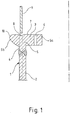
- connection profile 1 is designed as a rotationally symmetrical tubular profile and may for example be formed as a so-called monopile an offshore wind turbine, which receives a suitably trained connection profile in the form of a transition piece (Transition Piece) or in the form of a pipe section of a tower structure.
- Transition Piece transition piece
- connection profile 1 In the drawing, only part of the connection profile 1 is shown in section, the mirror-symmetric part of the connection profile 1 is not shown for reasons of simplification.
- connection profile 1 comprises a substantially continuous profile cross section, which is preferably cylindrical. Shown is a wall 2 of the continuous profile cross-section, to which an annular flange 3 is welded.
- the annular flange 3 comprises a wall portion 4 and a flange 5.
- the wall portion 4 of the annular flange 3 is welded on the shock side and in alignment with the wall 2 of the continuous cross-sectional profile.
- the flange body 5 comprises an inwardly projecting part 5a and an outwardly projecting part 5b.
- the terms “inside” and “outside” in the sense of the above definition designate in each case based on the tubular cross-section of the connection profile 1, the enclosed by the connection profile 1 inside and the corresponding applied page. "Inside” therefore means “enclosed by the profile cross-section” within the meaning of the invention.
- the inwardly projecting part 5a of the flange is provided with through openings 6, which are preferably arranged as a circular holes on a common bolt circle.
- the flange body 5 forms a support surface 7, which has an annular groove provided in the projection above the wall 2 of the continuous profile cross-section.
- the annular groove can at least temporarily record a part of a driving hood 9 that is only hinted at.
- the outer peripheral edge of the support surface 7 is provided with a phase or inclined surface 10, on which, for example, a skirt 11 (see FIG. 3 ) weldable.
- the support surface 7 can total inward, d. H. be slightly sloping or slightly inclined in the direction of the symmetry axis of the connection profile 1.
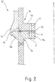
- FIG. 2 shows a flange 12 using a connection profile 1 according to the invention.
- the flange connection 12 comprises a first lower connection profile 1a and a second upper connection profile 1b.
- the first lower connection profile 1a is as a connection profile 1 according to FIG. 1 formed
- the second upper connection profile 1b is formed as a connection profile with an inner circumferential annular flange 13 which is designed as a normal ring flange with L-profile.
- the first lower connection profile 1a and the second upper connection profile 1b are connected to one another such that the passage openings 6 of the mutually facing support surfaces 7 of the annular flanges 3, 13 are arranged in alignment with one another.
- these recorded fasteners such as threaded bolts, threaded screws or the like are not shown.
- flange 12 takes the annular groove 8 of the first lower connection section 1a a sealing cord 14, which seals a butt joint 15 between the support surfaces 7.
- the flange 12 is covered to the outside in the region of the joint 15 with a sealing sleeve 16, which is the geometry of the flange 5 and the outwardly projecting part 5b of the flange 5 adapted and attached, for example, to the second upper connection profile. This can be fixed there form-fitting, non-positively and / or cohesively.
- the Sealing collar 16 may be formed as a circumferential elastomer seal or as a circumferential plastic collar.
- FIG. 3 Another variant of the flange connection 12 according to the invention is shown in FIG FIG. 3 shown, in FIG. 3 the same components with the same reference numerals as in the FIGS. 1 and 2 are designated.
- the first lower connection profile 1a at the in FIG. 3 illustrated variant of the flange 12 is substantially according to the connection profile 1 according to FIG. 1 formed, there is provided a the flange 3 of the first lower connection profile 1a edge bordering skirt 11, which was subsequently welded to the inclined surface 10 of the first lower connection profile 1a.
- connection profiles 1, 1a, 1b according to the invention are preferably formed as steel profiles, the skirt 17 may also be formed as a steel profile. Otherwise, the design of the first lower connection profile 1a corresponds to FIG FIG. 3 the design of the first lower connection profile 1a in FIG. 2 ,
- the skirt 17 is provided with one or more openings 17, which allow, for example, the handling by means of load hooks or shackles or the like.
- the flange connection is sealed with a sealing collar 16 which comprises a first leg 19a filling an annular space 18 between the skirt 11 and the second upper connection profile 1b.
- a second leg 19b of the sealing sleeve 16 engages over the skirt 11 on the outside.
- the skirt 17 is also provided with a drainage hole 20, which allows an approximately required drainage of the annular space 18.
- the Support surface 7 of the annular flange 3 in the outwardly projecting part 5b of the flange either cambered or concave form.
Landscapes
- Engineering & Computer Science (AREA)
- Architecture (AREA)
- Life Sciences & Earth Sciences (AREA)
- Chemical & Material Sciences (AREA)
- Materials Engineering (AREA)
- Wood Science & Technology (AREA)
- Civil Engineering (AREA)
- Structural Engineering (AREA)
- Wind Motors (AREA)
- Bridges Or Land Bridges (AREA)
Priority Applications (1)
| Application Number | Priority Date | Filing Date | Title |
|---|---|---|---|
| PL14194001T PL2884026T3 (pl) | 2013-12-12 | 2014-11-20 | Połączenie kołnierzowe konstrukcji budowli stanowiącej konstrukcję morską lub lądową oraz sposób wznoszenia konstrukcji budowli za pomocą połączenia kołnierzowego |
Applications Claiming Priority (2)
| Application Number | Priority Date | Filing Date | Title |
|---|---|---|---|
| DE102013020548 | 2013-12-12 | ||
| DE102014001996.9A DE102014001996A1 (de) | 2013-12-12 | 2014-02-17 | Anschlussprofil einer Bauwerksstruktur als Offshore- oder Onshore-Struktur und Flanschverbindung an einer solchen Bauwerksstruktur sowie Verfahren zur Errichtung einer Bauwerksstruktur unter Verwendung des Anschlussprofils |
Publications (3)
| Publication Number | Publication Date |
|---|---|
| EP2884026A2 EP2884026A2 (de) | 2015-06-17 |
| EP2884026A3 EP2884026A3 (de) | 2015-08-26 |
| EP2884026B1 true EP2884026B1 (de) | 2019-07-31 |
Family
ID=52020940
Family Applications (1)
| Application Number | Title | Priority Date | Filing Date |
|---|---|---|---|
| EP14194001.5A Active EP2884026B1 (de) | 2013-12-12 | 2014-11-20 | Flanschverbindung einer Bauwerksstruktur als Offshore- oder Onshore-Struktur sowie Verfahren zur Errichtung einer Bauwerksstruktur unter Verwendung der Flanschverbindung |
Country Status (4)
| Country | Link |
|---|---|
| EP (1) | EP2884026B1 (pl) |
| DE (1) | DE102014001996A1 (pl) |
| DK (1) | DK2884026T3 (pl) |
| PL (1) | PL2884026T3 (pl) |
Families Citing this family (4)
| Publication number | Priority date | Publication date | Assignee | Title |
|---|---|---|---|---|
| EP3141676B1 (en) * | 2015-09-14 | 2017-11-29 | innogy SE | Bolted joint of an offshore structure |
| DE102017106201A1 (de) * | 2017-03-22 | 2018-09-27 | Wobben Properties Gmbh | Flanschsegment für ein Windenergieanlagen-Stahlturmringsegment und Verfahren |
| US10472792B2 (en) * | 2017-05-16 | 2019-11-12 | General Electric Company | Tower flange for a wind turbine |
| NO348194B1 (en) * | 2022-03-11 | 2024-09-23 | Tp Products As | Flange element |
Family Cites Families (11)
| Publication number | Priority date | Publication date | Assignee | Title |
|---|---|---|---|---|
| CH675742A5 (pl) * | 1988-09-26 | 1990-10-31 | Fischer Ag Georg | |
| DE10160022A1 (de) * | 2001-12-06 | 2003-06-18 | Gen Electric | Verfahren zum Herstellen eines Turms einer Windkraftanlage, mit diesem Verfahren hergestellter Turm und Bauelemente zur Herstellung eines Turms |
| DE10230273B3 (de) * | 2002-07-05 | 2004-02-12 | Institut für Fertigteiltechnik und Fertigbau Weimar e.V. | Turm einer Windkraftanlage mit einem unteren Teil aus Spannbeton und einem aufgesetzten Stahlrohr |
| JP4575061B2 (ja) * | 2004-07-23 | 2010-11-04 | 第一建設機工株式会社 | 洋上風力発電施設の施工方法 |
| DE102008029651B3 (de) * | 2008-06-24 | 2010-04-08 | Repower Systems Ag | Turm einer Windenergieanlage |
| CN101778757B (zh) * | 2008-08-28 | 2013-06-12 | 三菱重工业株式会社 | 海上风力发电装置的建设方法及建设装置 |
| US8490337B2 (en) * | 2009-06-09 | 2013-07-23 | Thomas Nott Word, III | Structural flange connection system and method |
| EP2545271A2 (en) * | 2010-03-10 | 2013-01-16 | W3G Shipping Ltd | Offshore structures and associated apparatus and methods |
| US9004875B2 (en) * | 2011-03-11 | 2015-04-14 | General Electric Company | Flange and wind energy system |
| US20130180199A1 (en) * | 2012-01-17 | 2013-07-18 | Venkata Krishna Vadlamudi | Flange connection for a wind turbine and method of connecting parts of a wind turbine |
| DE102013012712A1 (de) * | 2013-08-01 | 2015-02-05 | Rwe Innogy Gmbh | Flanschverbindung an einer Offshore-Struktur |
-
2014
- 2014-02-17 DE DE102014001996.9A patent/DE102014001996A1/de not_active Withdrawn
- 2014-11-20 DK DK14194001T patent/DK2884026T3/da active
- 2014-11-20 PL PL14194001T patent/PL2884026T3/pl unknown
- 2014-11-20 EP EP14194001.5A patent/EP2884026B1/de active Active
Non-Patent Citations (1)
| Title |
|---|
| None * |
Also Published As
| Publication number | Publication date |
|---|---|
| DK2884026T3 (da) | 2019-11-04 |
| PL2884026T3 (pl) | 2020-03-31 |
| EP2884026A3 (de) | 2015-08-26 |
| EP2884026A2 (de) | 2015-06-17 |
| DE102014001996A1 (de) | 2015-06-18 |
Similar Documents
| Publication | Publication Date | Title |
|---|---|---|
| EP2011924B1 (de) | Offshore-Plattform | |
| EP2824257B1 (de) | Verfahren zur Herstellung und zum Errichten eines Rohrturmbauwerks | |
| EP2832938B1 (de) | Flanschverbindung an einer Offshore-Struktur | |
| EP2420623A2 (de) | Gründungsstruktur für eine Offshore-Windenergieanlage (Sandwich-Gründungsstruktur) | |
| EP2884026B1 (de) | Flanschverbindung einer Bauwerksstruktur als Offshore- oder Onshore-Struktur sowie Verfahren zur Errichtung einer Bauwerksstruktur unter Verwendung der Flanschverbindung | |
| DE2635126B2 (de) | Druckmittelbetätigte Halteeinrichtung | |
| AT405079B (de) | Unterseebohrstelle | |
| WO2008125082A2 (de) | Hydraulikstempel mit rechteckigen sicherungsdrähten | |
| EP2877638A1 (de) | Fundament für eine windenergieanlage | |
| EP2288771B1 (de) | Turm einer windenergieanlage | |
| DE102012011175A1 (de) | Turm für eine Windenergieanlage | |
| EP3323764B1 (de) | Hohlprofil | |
| EP3607147B1 (de) | Offshore bauwerk | |
| EP2169289A1 (de) | Mauerkragen | |
| EP3076013B1 (de) | Verfahren und verbindungsstruktur zur verbindung einer gründungsstruktur mit einer tragstruktur einer windenergieanlage und windenergieanlage | |
| DE102015209661A1 (de) | Verfahren zur Gründung eines Turmbauwerks sowie Onshore-Turmbauwerk | |
| DE102009007442A1 (de) | Brücke oder Brückenabschnitt | |
| DE102014118251A1 (de) | Verfahren zur Herstellung und zum Errichten eines Rohrturmbauwerks | |
| EP3542000B1 (de) | Verfahren zum rückbau von offshore gründungsstrukturen | |
| AT394248B (de) | Rohrkonstruktion zur herstellung eines gesteinsankers und/oder zur fluessigkeitsfoerderung | |
| DE102011054567A1 (de) | Turmbauwerk, Element zur Herstellung des Turmbauwerk und Verfahren zur Errichtung des Turmbauwerks | |
| DE102013008448B4 (de) | Verfahren und Vorrichtung zum nachträglichen Abdichten vom Erdreich umgebener Betonbauwerke mit Dichtungsfugen wie Tunneln | |
| EP4592455A1 (de) | Verbindungsanordnung und verfahren zum bereitstellen einer solchen verbindungsanordnung | |
| EP2873775B1 (de) | Verfahren zur Gründung eines Offshore-Bauwerks sowie Gründungspfahl zur Verwendung bei der Durchführung des Verfahrens | |
| DE202007005640U1 (de) | Sprengwirkungshemmender Gebäudeabschluss |
Legal Events
| Date | Code | Title | Description |
|---|---|---|---|
| PUAI | Public reference made under article 153(3) epc to a published international application that has entered the european phase |
Free format text: ORIGINAL CODE: 0009012 |
|
| 17P | Request for examination filed |
Effective date: 20141120 |
|
| AK | Designated contracting states |
Kind code of ref document: A2 Designated state(s): AL AT BE BG CH CY CZ DE DK EE ES FI FR GB GR HR HU IE IS IT LI LT LU LV MC MK MT NL NO PL PT RO RS SE SI SK SM TR |
|
| AX | Request for extension of the european patent |
Extension state: BA ME |
|
| PUAL | Search report despatched |
Free format text: ORIGINAL CODE: 0009013 |
|
| AK | Designated contracting states |
Kind code of ref document: A3 Designated state(s): AL AT BE BG CH CY CZ DE DK EE ES FI FR GB GR HR HU IE IS IT LI LT LU LV MC MK MT NL NO PL PT RO RS SE SI SK SM TR |
|
| AX | Request for extension of the european patent |
Extension state: BA ME |
|
| RIC1 | Information provided on ipc code assigned before grant |
Ipc: E04B 1/38 20060101ALI20150722BHEP Ipc: E04H 12/08 20060101AFI20150722BHEP Ipc: F16L 23/02 20060101ALI20150722BHEP |
|
| R17P | Request for examination filed (corrected) |
Effective date: 20160226 |
|
| RBV | Designated contracting states (corrected) |
Designated state(s): AL AT BE BG CH CY CZ DE DK EE ES FI FR GB GR HR HU IE IS IT LI LT LU LV MC MK MT NL NO PL PT RO RS SE SI SK SM TR |
|
| 17Q | First examination report despatched |
Effective date: 20160609 |
|
| STAA | Information on the status of an ep patent application or granted ep patent |
Free format text: STATUS: EXAMINATION IS IN PROGRESS |
|
| RAP1 | Party data changed (applicant data changed or rights of an application transferred) |
Owner name: INNOGY SE |
|
| GRAP | Despatch of communication of intention to grant a patent |
Free format text: ORIGINAL CODE: EPIDOSNIGR1 |
|
| STAA | Information on the status of an ep patent application or granted ep patent |
Free format text: STATUS: GRANT OF PATENT IS INTENDED |
|
| INTG | Intention to grant announced |
Effective date: 20190220 |
|
| RIN1 | Information on inventor provided before grant (corrected) |
Inventor name: WOERDEN, FLORIAN TOM Inventor name: FREISEN, HEINRICH JOSEF MICHAEL Inventor name: OTAIBI, WALID KH. A. AL Inventor name: BARTMINN, DANIEL Inventor name: LUEDDECKE, FALK |
|
| GRAS | Grant fee paid |
Free format text: ORIGINAL CODE: EPIDOSNIGR3 |
|
| GRAA | (expected) grant |
Free format text: ORIGINAL CODE: 0009210 |
|
| STAA | Information on the status of an ep patent application or granted ep patent |
Free format text: STATUS: THE PATENT HAS BEEN GRANTED |
|
| AK | Designated contracting states |
Kind code of ref document: B1 Designated state(s): AL AT BE BG CH CY CZ DE DK EE ES FI FR GB GR HR HU IE IS IT LI LT LU LV MC MK MT NL NO PL PT RO RS SE SI SK SM TR |
|
| REG | Reference to a national code |
Ref country code: CH Ref legal event code: EP Ref country code: GB Ref legal event code: FG4D Free format text: NOT ENGLISH |
|
| REG | Reference to a national code |
Ref country code: AT Ref legal event code: REF Ref document number: 1161053 Country of ref document: AT Kind code of ref document: T Effective date: 20190815 |
|
| REG | Reference to a national code |
Ref country code: IE Ref legal event code: FG4D Free format text: LANGUAGE OF EP DOCUMENT: GERMAN |
|
| REG | Reference to a national code |
Ref country code: DE Ref legal event code: R096 Ref document number: 502014012306 Country of ref document: DE |
|
| REG | Reference to a national code |
Ref country code: DK Ref legal event code: T3 Effective date: 20191030 |
|
| REG | Reference to a national code |
Ref country code: NL Ref legal event code: FP |
|
| REG | Reference to a national code |
Ref country code: LT Ref legal event code: MG4D |
|
| PG25 | Lapsed in a contracting state [announced via postgrant information from national office to epo] |
Ref country code: PT Free format text: LAPSE BECAUSE OF FAILURE TO SUBMIT A TRANSLATION OF THE DESCRIPTION OR TO PAY THE FEE WITHIN THE PRESCRIBED TIME-LIMIT Effective date: 20191202 Ref country code: BG Free format text: LAPSE BECAUSE OF FAILURE TO SUBMIT A TRANSLATION OF THE DESCRIPTION OR TO PAY THE FEE WITHIN THE PRESCRIBED TIME-LIMIT Effective date: 20191031 Ref country code: LT Free format text: LAPSE BECAUSE OF FAILURE TO SUBMIT A TRANSLATION OF THE DESCRIPTION OR TO PAY THE FEE WITHIN THE PRESCRIBED TIME-LIMIT Effective date: 20190731 Ref country code: HR Free format text: LAPSE BECAUSE OF FAILURE TO SUBMIT A TRANSLATION OF THE DESCRIPTION OR TO PAY THE FEE WITHIN THE PRESCRIBED TIME-LIMIT Effective date: 20190731 Ref country code: SE Free format text: LAPSE BECAUSE OF FAILURE TO SUBMIT A TRANSLATION OF THE DESCRIPTION OR TO PAY THE FEE WITHIN THE PRESCRIBED TIME-LIMIT Effective date: 20190731 Ref country code: NO Free format text: LAPSE BECAUSE OF FAILURE TO SUBMIT A TRANSLATION OF THE DESCRIPTION OR TO PAY THE FEE WITHIN THE PRESCRIBED TIME-LIMIT Effective date: 20191031 Ref country code: FI Free format text: LAPSE BECAUSE OF FAILURE TO SUBMIT A TRANSLATION OF THE DESCRIPTION OR TO PAY THE FEE WITHIN THE PRESCRIBED TIME-LIMIT Effective date: 20190731 |
|
| PG25 | Lapsed in a contracting state [announced via postgrant information from national office to epo] |
Ref country code: GR Free format text: LAPSE BECAUSE OF FAILURE TO SUBMIT A TRANSLATION OF THE DESCRIPTION OR TO PAY THE FEE WITHIN THE PRESCRIBED TIME-LIMIT Effective date: 20191101 Ref country code: ES Free format text: LAPSE BECAUSE OF FAILURE TO SUBMIT A TRANSLATION OF THE DESCRIPTION OR TO PAY THE FEE WITHIN THE PRESCRIBED TIME-LIMIT Effective date: 20190731 Ref country code: RS Free format text: LAPSE BECAUSE OF FAILURE TO SUBMIT A TRANSLATION OF THE DESCRIPTION OR TO PAY THE FEE WITHIN THE PRESCRIBED TIME-LIMIT Effective date: 20190731 Ref country code: AL Free format text: LAPSE BECAUSE OF FAILURE TO SUBMIT A TRANSLATION OF THE DESCRIPTION OR TO PAY THE FEE WITHIN THE PRESCRIBED TIME-LIMIT Effective date: 20190731 Ref country code: LV Free format text: LAPSE BECAUSE OF FAILURE TO SUBMIT A TRANSLATION OF THE DESCRIPTION OR TO PAY THE FEE WITHIN THE PRESCRIBED TIME-LIMIT Effective date: 20190731 Ref country code: IS Free format text: LAPSE BECAUSE OF FAILURE TO SUBMIT A TRANSLATION OF THE DESCRIPTION OR TO PAY THE FEE WITHIN THE PRESCRIBED TIME-LIMIT Effective date: 20191130 |
|
| PG25 | Lapsed in a contracting state [announced via postgrant information from national office to epo] |
Ref country code: TR Free format text: LAPSE BECAUSE OF FAILURE TO SUBMIT A TRANSLATION OF THE DESCRIPTION OR TO PAY THE FEE WITHIN THE PRESCRIBED TIME-LIMIT Effective date: 20190731 |
|
| PG25 | Lapsed in a contracting state [announced via postgrant information from national office to epo] |
Ref country code: RO Free format text: LAPSE BECAUSE OF FAILURE TO SUBMIT A TRANSLATION OF THE DESCRIPTION OR TO PAY THE FEE WITHIN THE PRESCRIBED TIME-LIMIT Effective date: 20190731 Ref country code: IT Free format text: LAPSE BECAUSE OF FAILURE TO SUBMIT A TRANSLATION OF THE DESCRIPTION OR TO PAY THE FEE WITHIN THE PRESCRIBED TIME-LIMIT Effective date: 20190731 Ref country code: EE Free format text: LAPSE BECAUSE OF FAILURE TO SUBMIT A TRANSLATION OF THE DESCRIPTION OR TO PAY THE FEE WITHIN THE PRESCRIBED TIME-LIMIT Effective date: 20190731 |
|
| PG25 | Lapsed in a contracting state [announced via postgrant information from national office to epo] |
Ref country code: IS Free format text: LAPSE BECAUSE OF FAILURE TO SUBMIT A TRANSLATION OF THE DESCRIPTION OR TO PAY THE FEE WITHIN THE PRESCRIBED TIME-LIMIT Effective date: 20200224 Ref country code: SK Free format text: LAPSE BECAUSE OF FAILURE TO SUBMIT A TRANSLATION OF THE DESCRIPTION OR TO PAY THE FEE WITHIN THE PRESCRIBED TIME-LIMIT Effective date: 20190731 Ref country code: SM Free format text: LAPSE BECAUSE OF FAILURE TO SUBMIT A TRANSLATION OF THE DESCRIPTION OR TO PAY THE FEE WITHIN THE PRESCRIBED TIME-LIMIT Effective date: 20190731 Ref country code: CZ Free format text: LAPSE BECAUSE OF FAILURE TO SUBMIT A TRANSLATION OF THE DESCRIPTION OR TO PAY THE FEE WITHIN THE PRESCRIBED TIME-LIMIT Effective date: 20190731 |
|
| REG | Reference to a national code |
Ref country code: DE Ref legal event code: R097 Ref document number: 502014012306 Country of ref document: DE |
|
| REG | Reference to a national code |
Ref country code: CH Ref legal event code: PL |
|
| PLBE | No opposition filed within time limit |
Free format text: ORIGINAL CODE: 0009261 |
|
| STAA | Information on the status of an ep patent application or granted ep patent |
Free format text: STATUS: NO OPPOSITION FILED WITHIN TIME LIMIT |
|
| PG2D | Information on lapse in contracting state deleted |
Ref country code: IS |
|
| PG25 | Lapsed in a contracting state [announced via postgrant information from national office to epo] |
Ref country code: MC Free format text: LAPSE BECAUSE OF FAILURE TO SUBMIT A TRANSLATION OF THE DESCRIPTION OR TO PAY THE FEE WITHIN THE PRESCRIBED TIME-LIMIT Effective date: 20190731 Ref country code: LU Free format text: LAPSE BECAUSE OF NON-PAYMENT OF DUE FEES Effective date: 20191120 Ref country code: LI Free format text: LAPSE BECAUSE OF NON-PAYMENT OF DUE FEES Effective date: 20191130 Ref country code: CH Free format text: LAPSE BECAUSE OF NON-PAYMENT OF DUE FEES Effective date: 20191130 Ref country code: IS Free format text: LAPSE BECAUSE OF FAILURE TO SUBMIT A TRANSLATION OF THE DESCRIPTION OR TO PAY THE FEE WITHIN THE PRESCRIBED TIME-LIMIT Effective date: 20191030 |
|
| 26N | No opposition filed |
Effective date: 20200603 |
|
| PG25 | Lapsed in a contracting state [announced via postgrant information from national office to epo] |
Ref country code: SI Free format text: LAPSE BECAUSE OF FAILURE TO SUBMIT A TRANSLATION OF THE DESCRIPTION OR TO PAY THE FEE WITHIN THE PRESCRIBED TIME-LIMIT Effective date: 20190731 |
|
| REG | Reference to a national code |
Ref country code: AT Ref legal event code: MM01 Ref document number: 1161053 Country of ref document: AT Kind code of ref document: T Effective date: 20191120 |
|
| PG25 | Lapsed in a contracting state [announced via postgrant information from national office to epo] |
Ref country code: AT Free format text: LAPSE BECAUSE OF NON-PAYMENT OF DUE FEES Effective date: 20191120 |
|
| PG25 | Lapsed in a contracting state [announced via postgrant information from national office to epo] |
Ref country code: CY Free format text: LAPSE BECAUSE OF FAILURE TO SUBMIT A TRANSLATION OF THE DESCRIPTION OR TO PAY THE FEE WITHIN THE PRESCRIBED TIME-LIMIT Effective date: 20190731 |
|
| PG25 | Lapsed in a contracting state [announced via postgrant information from national office to epo] |
Ref country code: HU Free format text: LAPSE BECAUSE OF FAILURE TO SUBMIT A TRANSLATION OF THE DESCRIPTION OR TO PAY THE FEE WITHIN THE PRESCRIBED TIME-LIMIT; INVALID AB INITIO Effective date: 20141120 Ref country code: MT Free format text: LAPSE BECAUSE OF FAILURE TO SUBMIT A TRANSLATION OF THE DESCRIPTION OR TO PAY THE FEE WITHIN THE PRESCRIBED TIME-LIMIT Effective date: 20190731 |
|
| PG25 | Lapsed in a contracting state [announced via postgrant information from national office to epo] |
Ref country code: MK Free format text: LAPSE BECAUSE OF FAILURE TO SUBMIT A TRANSLATION OF THE DESCRIPTION OR TO PAY THE FEE WITHIN THE PRESCRIBED TIME-LIMIT Effective date: 20190731 |
|
| P01 | Opt-out of the competence of the unified patent court (upc) registered |
Effective date: 20230530 |
|
| PGFP | Annual fee paid to national office [announced via postgrant information from national office to epo] |
Ref country code: NL Payment date: 20251119 Year of fee payment: 12 |
|
| PGFP | Annual fee paid to national office [announced via postgrant information from national office to epo] |
Ref country code: DE Payment date: 20251118 Year of fee payment: 12 |
|
| PGFP | Annual fee paid to national office [announced via postgrant information from national office to epo] |
Ref country code: GB Payment date: 20251120 Year of fee payment: 12 |
|
| PGFP | Annual fee paid to national office [announced via postgrant information from national office to epo] |
Ref country code: DK Payment date: 20251119 Year of fee payment: 12 |
|
| PGFP | Annual fee paid to national office [announced via postgrant information from national office to epo] |
Ref country code: FR Payment date: 20251125 Year of fee payment: 12 |
|
| PGFP | Annual fee paid to national office [announced via postgrant information from national office to epo] |
Ref country code: BE Payment date: 20251118 Year of fee payment: 12 |
|
| PGFP | Annual fee paid to national office [announced via postgrant information from national office to epo] |
Ref country code: IE Payment date: 20251120 Year of fee payment: 12 |
|
| PGFP | Annual fee paid to national office [announced via postgrant information from national office to epo] |
Ref country code: PL Payment date: 20251110 Year of fee payment: 12 |