EP2884018B1 - Vorrichtung für ein Straßenfahrzeug und Straßenfahrzeug mit der Vorrichtung - Google Patents
Vorrichtung für ein Straßenfahrzeug und Straßenfahrzeug mit der Vorrichtung Download PDFInfo
- Publication number
- EP2884018B1 EP2884018B1 EP14197304.0A EP14197304A EP2884018B1 EP 2884018 B1 EP2884018 B1 EP 2884018B1 EP 14197304 A EP14197304 A EP 14197304A EP 2884018 B1 EP2884018 B1 EP 2884018B1
- Authority
- EP
- European Patent Office
- Prior art keywords
- device holder
- suction pipe
- sludge trap
- road vehicle
- road
- Prior art date
- Legal status (The legal status is an assumption and is not a legal conclusion. Google has not performed a legal analysis and makes no representation as to the accuracy of the status listed.)
- Active
Links
- 239000010802 sludge Substances 0.000 claims description 45
- 238000004140 cleaning Methods 0.000 claims description 19
- 238000011010 flushing procedure Methods 0.000 claims description 5
- 239000000725 suspension Substances 0.000 description 15
- 238000010276 construction Methods 0.000 description 3
- 239000003599 detergent Substances 0.000 description 3
- 238000011161 development Methods 0.000 description 3
- 230000018109 developmental process Effects 0.000 description 3
- 239000012535 impurity Substances 0.000 description 3
- 239000007921 spray Substances 0.000 description 3
- 239000003795 chemical substances by application Substances 0.000 description 2
- 238000006073 displacement reaction Methods 0.000 description 2
- 230000000694 effects Effects 0.000 description 2
- 238000012423 maintenance Methods 0.000 description 2
- 239000004033 plastic Substances 0.000 description 2
- 238000005507 spraying Methods 0.000 description 2
- 238000010408 sweeping Methods 0.000 description 2
- 229910001018 Cast iron Inorganic materials 0.000 description 1
- 238000007792 addition Methods 0.000 description 1
- 210000000078 claw Anatomy 0.000 description 1
- 230000001419 dependent effect Effects 0.000 description 1
- 239000000463 material Substances 0.000 description 1
- 238000002360 preparation method Methods 0.000 description 1
- 239000002352 surface water Substances 0.000 description 1
Images


Classifications
-
- E—FIXED CONSTRUCTIONS
- E03—WATER SUPPLY; SEWERAGE
- E03F—SEWERS; CESSPOOLS
- E03F7/00—Other installations or implements for operating sewer systems, e.g. for preventing or indicating stoppage; Emptying cesspools
- E03F7/10—Wheeled apparatus for emptying sewers or cesspools
Definitions
- the invention relates to a device for a road vehicle, the device comprising at least one attachment having a device holder and attached to the device holder devices which are displaceable on the device holder at least transversely to a predetermined direction of travel of the road vehicle and of which at least one is a Senkkastendeckelheber wherein at least one of the devices mounted on the device holder is a mud-trap cleaner, the mud-trap cleaner having a suction tube routed to the device holder, and wherein the sink cap lifter and the mud trap cleaner form a road drain cleaner.
- Such a device for a road vehicle with the dirt traps of road drains to be cleaned, goes out of the DE 10 2014 022 121 A1 out.
- a laterally extendable cross member on which a control pulpit is arranged, which is accessible by an operator.
- a lid lifter and a suction line corresponding to the sludge trap are manually pivotable about a vertical axis by the operator, with the lid lifter and the suction line each supported on outriggers.
- the object of the invention is to provide such a device in order to be able to clean street drains in a simple manner faster and more cost-effectively with less personnel expenditure.
- the device for a road vehicle comprising at least one attachment having a device holder and attached to the device holder devices which are displaceable on the device holder at least transversely to a predetermined direction of travel of the road vehicle and at least one of which is a vertical box lid lifter, wherein at least one of the attached to the device holder devices Sludge trap cleaner, wherein the sludge trap has a run on the device holder suction pipe, and wherein the Senkkastendeckelheber and the sludge trap form a street drain cleaning device, according to the invention is characterized in that the Senkkastendeckelheber and sludge trap cleaner can be raised with a common hoist, the hoist associated with the cultivation is.
- a Senkkastendeckel is understood a mostly latticed, cast iron upper part of the road drain, which can be raised or removed for cleaning and control purposes and is often referred to as manhole cover.
- the device is then moved with the Senkkastendeckelheber to above a Senkkastendeckels a street drain, recorded the Senkkastendeckel with the Senkkastendeckelheber, raised and pivoted or moved until the suction pipe of the sludge trap cleaner can be inserted into the street drain or its downcomer.
- the Senkkastendeckel is at least as far laterally moved away from the street drain until its opening is completely freely accessible from above over its entire surface, that is free of their entire cross-section.
- the attachment according to the invention to the road vehicle designates the part of the device which can be attached to an interface of the road vehicle and forms the device.
- the interface may be standardized, for example, a device mounting plate, a Three-point suspension or the like, or be customized by taking advantage of existing on the road vehicle lifting and / or displacement device or other substructures.
- the device holder or a part of this may have for this purpose in elongated holes guided bolts, in particular bolts, with which the device holder or at least the part with the devices to a suspension or interface of the road vehicle or to the road vehicle can be aligned.
- the device holder or at least one of the devices in a preferred embodiment, parallel to a footprint of the road vehicle on which the attachment is fastened, displaced. It is thus achieved that the device or the device holder can be guided over the contact surface with as constant a distance as possible, so that the device can be assigned a uniform, identical stroke regardless of its position.
- All adjustable parts of the attachment and equipment such as Lifting, 9.verschiebe- and pivoting devices or the like, depending on the design can be hydraulically, pneumatically and / or electrically actuated. In particular, this can also be dependent on the possibilities of the respective road vehicle, so that advantageously existing systems are utilized.
- the countersink jack After the countersink jack has been positioned above the pavement, it must be lowered to lift the countersink lid. For this purpose, the Senkkastendeckelheber and the sludge trap cleaner with the common hoist can be raised.
- the countersunk lid lifter may comprise a hoist arranged on the appliance holder. This enables a single control of the countersunk lid lifter, ie lifting and lowering only the countersunk lid lifter, without having to move further devices or the entire device holder.
- the lifting mechanism of the Senkkastendeckelhebers must then take much lower forces when lifting than a hoist that lifts the entire device holder and can therefore be smaller and cheaper.
- the devices are always arranged in a predetermined, equal distance from each other.
- the Senkkastendeckel have introduced into the street drain suction pipe of the mud trap and the Senkkastendeckelheber while a distance corresponding to at least the width with which a Senkkastendeckel opposite the Senkkastendeckelheber projecting laterally in the direction of the sludge trap cleaner.
- This ensures that a lowered with the Senkkastendeckelheberer Senkkastendeckel is not held over the opening of the road drain and its entire cross-sectional area is freely accessible.
- the distance between the suction pipe of the mud trap, which can be inserted into the street drain, and the Senkkastendeckelheber is at least 130 mm.
- the Senkkastendeckelheber is rotatably supported, in particular infinitely rotatable in at least one direction, on the device holder.
- This is supported on a vertically aligned shaft and can rotate about a vertical axis and preferably by means of a hydraulic motor driven, that is rotated, be.
- Road accesses that are difficult to access in curves or other non-straight road sections can then also be inclined with the road vehicle having the device be approached and the countersunk lid lifter are aligned at the position of the road drain by turning to this.
- the most extensive independence of the Senkkastendeckelhebers of the shape of the street gullies can also be achieved by having at least one magnet, in particular at least one hydraulically actuated permanent lifting magnet or at least one electromagnet.
- the permanent lifting magnet is a particularly cost-effective and easily hydraulically or pneumatically controllable with a cylinder solution in which a permanent magnet is moved with the cylinder in a box.
- the permanent lifting magnet can also be moved via an oil motor or an electric motor or the like by means of an eccentric rod.
- the electromagnet to be provided is easily switched on and off electrically.
- the countersunk lid lifter can also have a gripper or a claw, with which or which is gripped in the lattice-shaped upper part to lift the Senkkastendeckel.
- the Senkkastendeckelheber or its magnet can be tilted so that it can be optimally adapted to curved roads or surfaces.
- the countersink lid lifter has an adjusting device with a spindle, which can be actuated, for example, by an electric motor or a hand crank.
- the sludge trap cleaner or at least the suction pipe of the sludge trap cleaner can be connected in a further embodiment with a boom above the Senkkastendeckelhebers to the device holder, in which case the distance between the suction pipe and Senkkastendeckelheber is defined by the boom and a constant distance between them is guaranteed.
- the suction tube with boom is further provided that the suction pipe of the mud trap with the boom is mounted in at least a partial area around the Senkkastendeckelheber pivotally mounted on the device holder. This can also be parked or otherwise difficult to reach by other obstacles road courses are easily controlled, which would not be achievable with a non-pivoting or laterally projecting suction tube.
- the suction tube can have a pivoting range which is limited by at least two stops.
- the pivoting range is 90 ° in the horizontal, wherein a first end position of the boom is set at an angle of 90 ° to the direction of travel of the road vehicle and a second end position is aligned in the direction of travel, the suction tube is preferably arranged in the second end position in front of the Senkkastendeckelheber ,
- the pivoting range can also be at least 120 °, in particular at least 150 ° or up to 180 °.
- the sludge trap with the boom in the direction of travel is arranged in front of or behind the Senkkastendeckelheber, sludge trap and Senkkastendeckelheber are mutually supported in the direction of travel slidably on the device holder.
- one of the devices can also be movable relative to the other device in a further alternative embodiment.
- the Senkkastendeckelheber be relatively movable to the sludge trap cleaner or at least the suction pipe of the sludge trap, then by moving, pivoting, rotating or tilting the Senkkastendeckelhebers with the Senkkastendeckel the road is released, so that the suction pipe is inserted into this.
- Suction tube and Senkkastendeckelheber the device are then in a starting position of the movable relative to the intake manifold Senkkastendeckelheber Device advantageously one above the other, in particular aligned one above the other, arranged.
- Senkkastendeckelheber Device advantageously one above the other, in particular aligned one above the other, arranged.
- the countersunk lid lifter is then assigned to a sliding, pivoting, rotating or tilting device, which is to be arranged additionally or alternatively to the displacement device of the device holder. Greater flexibility with regard to the operating and control options can be achieved by assigning a sliding, pivoting, rotating or tilting device to both the vertical box lid lifter and the sludge trap cleaner.
- the suction pipe is associated with a lifting mechanism of the sludge trap, with this relative to the Senkkastendeckelheber and / or the device holder movable, that is in a substantially vertical Direction is raised and / or lowered, is.
- This hoist can be composed of a lifting cylinder, in particular a hydraulic cylinder and a guide rod arranged parallel to the suction tube, on the distance to a connection of the lifting cylinder and suction tube at least one guide sleeve formed on the suction tube is displaceable.
- the hoist associated with the suction tube advantageously has a stroke of at least 500 mm, in particular at least 600 mm, in particular at least 800 mm.
- the suction pipe can also be made telescopic, with a telescoping part of the suction pipe being insertable into the sludge trap of the road drain. At least the insertable into the street drain, especially telescopic part of the suction pipe can also be designed as a removable end piece, so that it is easily replaceable in case of damage.
- the suction tube can be controlled relative to the rest of the creator holder, so that the suction tube during cleaning within the street drain back and forth movable or pivotable or reciprocally movable and pivoted.
- the suction pipe can then be guided within corners of the road to remove all dirt therefrom.
- the road vehicle or the rest of the device holder must not be moved with appropriate training during cleaning.
- a corresponding individual control of the suction tube can be combined according to the invention with each embodiment of the device, wherein at a predetermined, fixed distance from each other arranged intake manifold and Senkkastendeckelheber, the distance is to be defined such that this is either on a middle position of the intake manifold or by the einzel Kunststoffungs facultye maximum deflection of the suction tube specified minimum distance applies. Even road drains with a below the Senkkastendeckels widening cross section can be completely cleaned in a simple manner.
- at least one lower section of the suction pipe is formed by a flexible hose made of plastic or rubber, which deforms flexibly when pressure acts on it.
- the suction tube can be assigned at least one guide roller, along which a guide rail of the suction tube can be guided.
- This guide rail may consist of a formed on the suction pipe flat profile.
- the suction pipe is connected to a vacuum generator and a collecting container of the device.
- Both the collecting container and the vacuum generator can in one, in particular in a common, construction for the road vehicle be arranged.
- a corresponding structure may be designed differently, for example with regard to its mounting options on the road vehicle, dimensions or receiving volume of the collecting container.
- a spring-loaded flange connection is advantageously formed, with which a simple emptying of the collecting container is ensured by tilting it, for example, and at the same time creating a secure, sealed connection between the assembly and the suction pipe.
- the suction tube is pressed with a flange-like end against a likewise flange-shaped connecting arc of the collecting container.
- Another connection does not exist.
- the flange-like end of the suction tube in a further embodiment, a spring element associated with which it is received in a holder, so that an accurate alignment of the flange-like end is ensured.
- the flange-like end of the suction tube or the holder with the spring element is also arranged above a cab of the road vehicle to ensure the shortest possible distance between an inserted into a street drain end of the suction pipe and the sump.
- a latching mechanism can additionally be provided which secures the spring-loaded flange.
- a hydraulically adjustable end of the suction tube in addition to or supporting the spring element, a cylinder is actuated. The cylinder could then be coupled in a further embodiment with an emptying flap of the collecting container or a cover flap of the structure and its control, so that the flange connection is automatically released when emptying the collecting container.
- the suction pipe at its open end may also be associated with a surrounding jacket element, with which a road to be cleaned road drain with the suction pipe attached to the outside can be sealed is. All, applied by means of the vacuum generator suction thus acts on the dirt in the street drain and can be particularly effectively sucked.
- the jacket element is movable in the longitudinal direction of the suction pipe relative thereto. The jacket element can thus be lowered down to the street or the surface of the street drain, with an upper seal on or to the suction tube being ensured by means of a plastic sleeve sliding on the suction tube.
- the relative movement of the jacket member to the suction tube can be achieved by gas spring, with which the jacket element can be pressed in the direction of footprint of the road vehicle.
- Preferred material for the shell element is at least at its alsminden on the surface rubber, such as a rubber apron or the like.
- the intake manifold may be associated with an air supply line through which air is additionally blown into the roadway to be cleaned during the cleaning of the road drains and which thus causes a better release of adhering dirt.
- an air supply line through which air is additionally blown into the roadway to be cleaned during the cleaning of the road drains and which thus causes a better release of adhering dirt.
- the air supply line is combined with the jacket element in order to achieve an even better cleaning performance, so that air can be introduced into the space bounded by the jacket element with the air supply line.
- the part of the sludge trap to be introduced into a street drain can also have at least one rinsing nozzle or spray nozzle, in particular at least two rinsing or spraying nozzles, in particular at least four rinsing or spraying nozzles, a rinsing device with the hardened deposits and impurities be solved with high pressure first, before they are sucked into the sump with the suction tube.
- Flushing nozzle and one of these associated Flushing line can continue to be integrated into the suction tube, so that suction tube, flushing nozzle and flushing line form a unit.
- One of the rinsing nozzle associated rinsing agent container with a detergent pump may be integrated together with the collecting container and the vacuum generator in a common structure for the road vehicle, wherein rinsing agent container and rinsing nozzle are connected to each other via the rinsing line.
- Both the spray nozzle for detergent and the air supply can be directed at least with a partial flow against an upper edge of the street drain, in particular the seat of the Senkkastendeckels to clean them with high pressure.
- the suction pipe may also have lateral openings, which are held during the cleaning of the road drains in the amount of the upper edge of the road drain and thus additionally generate a suction effect in this area.
- the device holder may have a support wheel, in particular a height-adjustable support wheel, of which a part is picked up when lifting the countersunk lid on the suspension load.
- this jockey wheel can be hydraulically, pneumatically or electrically actuated and controlled, that is to say lowered, if necessary, during the lifting of the countersunk box lid onto a road or footprint.
- a constant pressure of the support wheel on the road or surface can be exercised and maintained.
- a suspension of the support wheel can be provided.
- this suspension of the device consists of at least two support wheels, which are each arranged at the interface or the suspension opposite front corners of the attachment. An additional support can be achieved in that in addition to the two front support wheels at least one further centrally disposed near the suspension support wheel of the chassis is provided.
- the device is advantageously connected to the road vehicle at least two points spaced apart from one another.
- the attachment with the device is then supported by the chassis always at least three points by the chassis or the road vehicle and the chassis, which may be provided depending on the configuration of the attachment, a chassis with more wheels, for example, if the sump or the detergent container integrated into the cultivation.
- the support wheels of the chassis are each rotatable about a vertical axis, in particular infinitely rotatable, so that the attachment to the chassis follows in a simple manner predetermined by the road vehicle direction of travel.
- a safe even in road bumps, gradients and the like connection of the attachment with chassis to the road vehicle can be achieved by the suspension is designed floating on the road vehicle. By unevenness of the footprint of road vehicle and cultivation-related movements of these relative to each other are then compensated on the suspension.
- the invention relates to a road vehicle for cleaning road courses, comprising a device comprising at least one attachment having a device holder and attached to the device holder devices which are displaceable on the device holder at least transversely to a predetermined direction of travel of the road vehicle and of which at least one is a countersunk lid lifter, wherein at least one of the appliances attached to the appliance holder is a mud-trap cleaner, the mud-trap cleaner having a suction tube carried on the appliance holder, and wherein the countersink lid lifter and the mud trap cleaner form a road drain cleaner.
- This vehicle is characterized in that the Senkkastendeckelheber and the sludge trap cleaner can be raised with a common hoist, the hoist is assigned to the attachment or the road vehicle to which the attachment is attachable.
- the corresponding road vehicle may represent a special system which is adapted only to this one device or is modified in such a way that the road vehicle and the device form a unit which is firmly connected to one another. Such a special system is then used exclusively for the cleaning of road drains. Instead of such a special system cultivation and / or construction of the device can also be designed as Konan- or swap bodies of a road vehicle intended for various purposes.
- Road vehicles that can accommodate appropriate attachments and structures of the device for example, a UNIMOG, a MultiCar or the like, which are summarized in the broadest sense by the term "equipment carrier " .
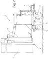
- Fig. 1 is a road vehicle 1 with an attachment 2 and a structure 3 of a device according to the invention.
- the structure 3 is composed essentially of a collecting container and a vacuum generator and is connected to the attachment 2 via a suction pipe 4 of a mud trap cleaner 5.
- a spring-loaded flange connection 7 is formed, with which one end of the suction pipe 4 against the Terminal bend 6 is pressed.
- the end of the suction tube 4 is received in a spring element 8. Details of the flange connection 7 are in particular again in FIG Fig. 5 shown.
- the extension 2 has, in addition to the sludge trap 5 with the suction pipe 4 to a device holder 9, to which both the suction pipe 4 of the sludge trap 5 and a Senkkastendeckelheber 10 and a support wheel 11 are attached.
- the device holder 9 of the attachment 2 is fastened to a suspension 12 of the road vehicle 1, the suspension 12 having a lifting mechanism 13 and a side shifting device 14. With these, the device holder 9 or the countersunk lid lifter 10 and the sludge trap cleaner 5 can be raised and lowered or moved laterally to the road vehicle 1.
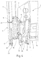
- the Senkkastendeckelheber 10 is still a from Fig. 2 associated hydraulic cylinder 15, with which a permanent lifting magnet of the Senkkastendeckelhebers 10 in a box this can be moved up and down.
- the hydraulic cylinder 15 is arranged substantially in a horizontal, in particular parallel to a footprint of a road vehicle.
- a suction pipe 4 associated hoist of the mud trap 5 can be seen, which is as well as the permanent lifting magnet via a hydraulic cylinder 16 is actuated and with the suction tube 4 is lowered into a street drain or a downcomer of the road expiry andRadiohebbar.
- the suction tube 4 is thus relative to the rest of the device holder 9 with the Senkkastendeckelheber 10 movable.
- the support wheel 11 is associated with a plurality of tension springs, which are tensioned in response to the load acting on the support wheel 11 when lifting a Senkkastendeckels, wherein load is taken from the suspension 12 of the road vehicle 1.
- the device When cleaning a street run, the device is now moved up with the road vehicle 1 to a street run until the countersunk lid lifter 10 is arranged above a Senkkastendeckels the road course.
- the attachment if necessary, moved by means of the side shift device 14 to the left or right of the road vehicle 1 in the direction of travel.
- the suction pipe 4 is raised by means of the hydraulic cylinder 16 in its initial position and lowered the Senkkastendeckel again on the road.
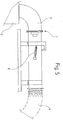
- the second version of the cultivation according to Fig. 3 differs from the first embodiment only in that not the device holder 9 but the Senkkastendeckelheber 10 a hoist 17 is assigned, which in turn has a further hydraulic cylinder.
- the suspension 12 of the road vehicle 1 is therefore assigned only a 9.verstell Rhein.
- Both the Senkkastendeckelheber 10 and the suction pipe 4 of the mud trap 5 is a hoist assigned 13 'with which they are movable relative to the device holder 9, wherein the device holder 9 itself by means of a hydraulic cylinder of a side shift 14 transverse to a direction of travel of the road vehicle 1 a shift of mud trap cleaner 5 and Drop box lid lifter 10 allows.
- the suction pipe 4 of the mud trap cleaner 5 is connected via a boom 18 pivotally connected to the device holder 9, wherein the boom 18 has a pivoting range of 90 degrees, so that the suction pipe 4 from the illustrated first lateral end position to a second end position in the direction of travel in front of the Senkkastendeckelheber 10 is pivotable.
- the pivoting range of the boom 18 is limited by stops 19.
- the suction pipe 4 is designed to be telescopic, wherein a telescoping part 4 'of the suction pipe 4 can be actuated by means of a further hydraulic cylinder.
- a spray nozzle 20 is also attached to a Spül effetsabêt 20 ', wherein the part of the suction pipe 4 with the Spül effetsabterrorism 20' and the telescopic part 4 'on a flange 21 of the device is removable and replaceable.
- this embodiment also includes an oil motor 22 for raising and lowering the valley box lid lifter 10 via an eccentric bar.
Landscapes
- Health & Medical Sciences (AREA)
- Life Sciences & Earth Sciences (AREA)
- Engineering & Computer Science (AREA)
- Hydrology & Water Resources (AREA)
- Public Health (AREA)
- Water Supply & Treatment (AREA)
- Sewage (AREA)
Priority Applications (1)
| Application Number | Priority Date | Filing Date | Title |
|---|---|---|---|
| PL14197304T PL2884018T3 (pl) | 2013-12-11 | 2014-12-11 | Urządzenie dla pojazdu drogowego i pojazd drogowy z urządzeniem |
Applications Claiming Priority (2)
| Application Number | Priority Date | Filing Date | Title |
|---|---|---|---|
| DE102013020509 | 2013-12-11 | ||
| DE202014007737.1U DE202014007737U1 (de) | 2014-09-30 | 2014-09-30 | Vorrichtung für ein Straßenfahrzeug und Straßenfahrzeug mit der Vorrichtung |
Publications (2)
| Publication Number | Publication Date |
|---|---|
| EP2884018A1 EP2884018A1 (de) | 2015-06-17 |
| EP2884018B1 true EP2884018B1 (de) | 2017-08-16 |
Family
ID=52101108
Family Applications (1)
| Application Number | Title | Priority Date | Filing Date |
|---|---|---|---|
| EP14197304.0A Active EP2884018B1 (de) | 2013-12-11 | 2014-12-11 | Vorrichtung für ein Straßenfahrzeug und Straßenfahrzeug mit der Vorrichtung |
Country Status (2)
| Country | Link |
|---|---|
| EP (1) | EP2884018B1 (pl) |
| PL (1) | PL2884018T3 (pl) |
Cited By (1)
| Publication number | Priority date | Publication date | Assignee | Title |
|---|---|---|---|---|
| DE102021101043A1 (de) | 2020-01-23 | 2021-07-29 | Gerold Hinrichs | Vorrichtung zur Reinigung von Oberflächenwasserablaufeinrichtungen und Kanalisationszugängen |
Families Citing this family (3)
| Publication number | Priority date | Publication date | Assignee | Title |
|---|---|---|---|---|
| DE202017107533U1 (de) * | 2017-12-11 | 2018-02-01 | Gerold Hinrichs | Vorrichtung für ein Straßenfahrzeug |
| IT201800007958A1 (it) * | 2018-08-08 | 2020-02-08 | Borghi Assali Srl | Apparato per la pulizia di caditoie stradali |
| CN110158755A (zh) * | 2019-06-26 | 2019-08-23 | 徐州徐工环境技术有限公司 | 一种下水道疏通清洗车的臂架组件及下水道疏通清洗车 |
Family Cites Families (4)
| Publication number | Priority date | Publication date | Assignee | Title |
|---|---|---|---|---|
| FR1145717A (fr) * | 1956-01-07 | 1957-10-29 | Sovel Soc | Véhicule aspirateur de matières liquides ou semi-liquides telles que des boues |
| DE19616291A1 (de) * | 1995-09-02 | 1997-03-06 | Dieter Schmeh | Vorrichtung zum Reinigen von Sinkkästen |
| DE102004022121B4 (de) * | 2004-05-05 | 2012-02-09 | Karl Wiedemann | Fahrzeug mit einer Vorrichtung zur Reinigung eines Schmutzfangs |
| DE202010016532U1 (de) * | 2010-12-13 | 2011-02-17 | Assmann, Peter | Kanalreinigungsfahrzeug |
-
2014
- 2014-12-11 PL PL14197304T patent/PL2884018T3/pl unknown
- 2014-12-11 EP EP14197304.0A patent/EP2884018B1/de active Active
Non-Patent Citations (1)
| Title |
|---|
| None * |
Cited By (1)
| Publication number | Priority date | Publication date | Assignee | Title |
|---|---|---|---|---|
| DE102021101043A1 (de) | 2020-01-23 | 2021-07-29 | Gerold Hinrichs | Vorrichtung zur Reinigung von Oberflächenwasserablaufeinrichtungen und Kanalisationszugängen |
Also Published As
| Publication number | Publication date |
|---|---|
| EP2884018A1 (de) | 2015-06-17 |
| PL2884018T3 (pl) | 2018-01-31 |
Similar Documents
| Publication | Publication Date | Title |
|---|---|---|
| EP2884018B1 (de) | Vorrichtung für ein Straßenfahrzeug und Straßenfahrzeug mit der Vorrichtung | |
| EP3495577B1 (de) | Vorrichtung für ein strassenfahrzeug und strassenfahrzeug mit solch einer vorrichtung | |
| EP2778286B1 (de) | Vorbau für Straßenreinigungsfahrzeug | |
| EP0762966B1 (de) | Vorrichtung zur demontage von fahrzeugen, insbesondere zu deren trockenlegung | |
| DE102010017608A1 (de) | Geräteträger und Ausleger für Reinigungsgeräte und Verfahren zur Steuerung eines Geräteträgers | |
| DE60124652T2 (de) | Vorrichtung zum Absaugen von Restwasser auf Pflaster- oder Betonflächen | |
| CH598422A5 (en) | Mobile tunnel cleaning and spraying machine | |
| DE10237431B4 (de) | Verfahren und Reinigungsfahrzeug zur Innenreinigung eines Tanks | |
| DE102015006940A1 (de) | Reinigungsvorrichtung für Reifen oder Gleisketten eines Fahrzeugs | |
| DE102011120115A1 (de) | Kanalreinigungsfahrzeug | |
| DE2145715A1 (de) | Kehrmaschine mit rotierenden Drehbürsten | |
| EP3735825A1 (de) | Vorrichtung zum abmisten von höfen und wiesen | |
| DE202014007737U1 (de) | Vorrichtung für ein Straßenfahrzeug und Straßenfahrzeug mit der Vorrichtung | |
| WO2006131001A1 (de) | Reifenwaschanlage | |
| DE3802034A1 (de) | Vorrichtung zum bewegen von schachtdeckeln | |
| DE19955424C2 (de) | Einrichtung und Verfahren zur Reinigung eines der Aufnahme von verunreinigtem Wasser dienenden Behälters | |
| DE10162477B4 (de) | Vorrichtung zur Reinigung eines Behälters für radioaktive Reststoffe | |
| DE102019112257B4 (de) | Vorrichtung zum Abmisten von Höfen und Wiesen | |
| DE202020102582U1 (de) | Vorrichtung zum Abmisten von Höfen und Wiesen | |
| DE202021103586U1 (de) | Vorrichtung zum Abmisten von Höfen und Wiesen und Sammelwalze | |
| DE102004022121B4 (de) | Fahrzeug mit einer Vorrichtung zur Reinigung eines Schmutzfangs | |
| DE102021101043A1 (de) | Vorrichtung zur Reinigung von Oberflächenwasserablaufeinrichtungen und Kanalisationszugängen | |
| DE10022874A1 (de) | Fahrzeug zum Lösen und Absaugen von Verunreinigungen aus Straßenabfläufen | |
| DE102004022120B4 (de) | Vorrichtung zur Reinigung kommunaler Einrichtungen im Straßenbereich | |
| DE4024298A1 (de) | Vorrichtung zum abtragen von beton mittels wenigstens eines hochdruck-fluessigkeitsstrahles, insbes. hochdruck-wasserstrahles |
Legal Events
| Date | Code | Title | Description |
|---|---|---|---|
| PUAI | Public reference made under article 153(3) epc to a published international application that has entered the european phase |
Free format text: ORIGINAL CODE: 0009012 |
|
| 17P | Request for examination filed |
Effective date: 20141211 |
|
| AK | Designated contracting states |
Kind code of ref document: A1 Designated state(s): AL AT BE BG CH CY CZ DE DK EE ES FI FR GB GR HR HU IE IS IT LI LT LU LV MC MK MT NL NO PL PT RO RS SE SI SK SM TR |
|
| AX | Request for extension of the european patent |
Extension state: BA ME |
|
| R17P | Request for examination filed (corrected) |
Effective date: 20151102 |
|
| RBV | Designated contracting states (corrected) |
Designated state(s): AL AT BE BG CH CY CZ DE DK EE ES FI FR GB GR HR HU IE IS IT LI LT LU LV MC MK MT NL NO PL PT RO RS SE SI SK SM TR |
|
| 17Q | First examination report despatched |
Effective date: 20160512 |
|
| GRAP | Despatch of communication of intention to grant a patent |
Free format text: ORIGINAL CODE: EPIDOSNIGR1 |
|
| INTG | Intention to grant announced |
Effective date: 20170403 |
|
| GRAS | Grant fee paid |
Free format text: ORIGINAL CODE: EPIDOSNIGR3 |
|
| GRAA | (expected) grant |
Free format text: ORIGINAL CODE: 0009210 |
|
| AK | Designated contracting states |
Kind code of ref document: B1 Designated state(s): AL AT BE BG CH CY CZ DE DK EE ES FI FR GB GR HR HU IE IS IT LI LT LU LV MC MK MT NL NO PL PT RO RS SE SI SK SM TR |
|
| REG | Reference to a national code |
Ref country code: GB Ref legal event code: FG4D Free format text: NOT ENGLISH |
|
| REG | Reference to a national code |
Ref country code: CH Ref legal event code: EP |
|
| REG | Reference to a national code |
Ref country code: IE Ref legal event code: FG4D Free format text: LANGUAGE OF EP DOCUMENT: GERMAN |
|
| REG | Reference to a national code |
Ref country code: AT Ref legal event code: REF Ref document number: 919179 Country of ref document: AT Kind code of ref document: T Effective date: 20170915 |
|
| REG | Reference to a national code |
Ref country code: DE Ref legal event code: R096 Ref document number: 502014005040 Country of ref document: DE |
|
| REG | Reference to a national code |
Ref country code: CH Ref legal event code: NV Representative=s name: PATENTANWAELTE SCHAAD, BALASS, MENZL AND PARTN, CH |
|
| REG | Reference to a national code |
Ref country code: NL Ref legal event code: FP |
|
| REG | Reference to a national code |
Ref country code: FR Ref legal event code: PLFP Year of fee payment: 4 |
|
| REG | Reference to a national code |
Ref country code: LT Ref legal event code: MG4D |
|
| PG25 | Lapsed in a contracting state [announced via postgrant information from national office to epo] |
Ref country code: LT Free format text: LAPSE BECAUSE OF FAILURE TO SUBMIT A TRANSLATION OF THE DESCRIPTION OR TO PAY THE FEE WITHIN THE PRESCRIBED TIME-LIMIT Effective date: 20170816 Ref country code: FI Free format text: LAPSE BECAUSE OF FAILURE TO SUBMIT A TRANSLATION OF THE DESCRIPTION OR TO PAY THE FEE WITHIN THE PRESCRIBED TIME-LIMIT Effective date: 20170816 Ref country code: NO Free format text: LAPSE BECAUSE OF FAILURE TO SUBMIT A TRANSLATION OF THE DESCRIPTION OR TO PAY THE FEE WITHIN THE PRESCRIBED TIME-LIMIT Effective date: 20171116 Ref country code: SE Free format text: LAPSE BECAUSE OF FAILURE TO SUBMIT A TRANSLATION OF THE DESCRIPTION OR TO PAY THE FEE WITHIN THE PRESCRIBED TIME-LIMIT Effective date: 20170816 |
|
| PG25 | Lapsed in a contracting state [announced via postgrant information from national office to epo] |
Ref country code: ES Free format text: LAPSE BECAUSE OF FAILURE TO SUBMIT A TRANSLATION OF THE DESCRIPTION OR TO PAY THE FEE WITHIN THE PRESCRIBED TIME-LIMIT Effective date: 20170816 Ref country code: LV Free format text: LAPSE BECAUSE OF FAILURE TO SUBMIT A TRANSLATION OF THE DESCRIPTION OR TO PAY THE FEE WITHIN THE PRESCRIBED TIME-LIMIT Effective date: 20170816 Ref country code: RS Free format text: LAPSE BECAUSE OF FAILURE TO SUBMIT A TRANSLATION OF THE DESCRIPTION OR TO PAY THE FEE WITHIN THE PRESCRIBED TIME-LIMIT Effective date: 20170816 Ref country code: BG Free format text: LAPSE BECAUSE OF FAILURE TO SUBMIT A TRANSLATION OF THE DESCRIPTION OR TO PAY THE FEE WITHIN THE PRESCRIBED TIME-LIMIT Effective date: 20171116 Ref country code: GR Free format text: LAPSE BECAUSE OF FAILURE TO SUBMIT A TRANSLATION OF THE DESCRIPTION OR TO PAY THE FEE WITHIN THE PRESCRIBED TIME-LIMIT Effective date: 20171117 Ref country code: IS Free format text: LAPSE BECAUSE OF FAILURE TO SUBMIT A TRANSLATION OF THE DESCRIPTION OR TO PAY THE FEE WITHIN THE PRESCRIBED TIME-LIMIT Effective date: 20171216 |
|
| PG25 | Lapsed in a contracting state [announced via postgrant information from national office to epo] |
Ref country code: DK Free format text: LAPSE BECAUSE OF FAILURE TO SUBMIT A TRANSLATION OF THE DESCRIPTION OR TO PAY THE FEE WITHIN THE PRESCRIBED TIME-LIMIT Effective date: 20170816 Ref country code: CZ Free format text: LAPSE BECAUSE OF FAILURE TO SUBMIT A TRANSLATION OF THE DESCRIPTION OR TO PAY THE FEE WITHIN THE PRESCRIBED TIME-LIMIT Effective date: 20170816 Ref country code: RO Free format text: LAPSE BECAUSE OF FAILURE TO SUBMIT A TRANSLATION OF THE DESCRIPTION OR TO PAY THE FEE WITHIN THE PRESCRIBED TIME-LIMIT Effective date: 20170816 |
|
| REG | Reference to a national code |
Ref country code: DE Ref legal event code: R097 Ref document number: 502014005040 Country of ref document: DE |
|
| PG25 | Lapsed in a contracting state [announced via postgrant information from national office to epo] |
Ref country code: EE Free format text: LAPSE BECAUSE OF FAILURE TO SUBMIT A TRANSLATION OF THE DESCRIPTION OR TO PAY THE FEE WITHIN THE PRESCRIBED TIME-LIMIT Effective date: 20170816 Ref country code: SM Free format text: LAPSE BECAUSE OF FAILURE TO SUBMIT A TRANSLATION OF THE DESCRIPTION OR TO PAY THE FEE WITHIN THE PRESCRIBED TIME-LIMIT Effective date: 20170816 Ref country code: SK Free format text: LAPSE BECAUSE OF FAILURE TO SUBMIT A TRANSLATION OF THE DESCRIPTION OR TO PAY THE FEE WITHIN THE PRESCRIBED TIME-LIMIT Effective date: 20170816 |
|
| PLBE | No opposition filed within time limit |
Free format text: ORIGINAL CODE: 0009261 |
|
| STAA | Information on the status of an ep patent application or granted ep patent |
Free format text: STATUS: NO OPPOSITION FILED WITHIN TIME LIMIT |
|
| 26N | No opposition filed |
Effective date: 20180517 |
|
| PG25 | Lapsed in a contracting state [announced via postgrant information from national office to epo] |
Ref country code: SI Free format text: LAPSE BECAUSE OF FAILURE TO SUBMIT A TRANSLATION OF THE DESCRIPTION OR TO PAY THE FEE WITHIN THE PRESCRIBED TIME-LIMIT Effective date: 20170816 |
|
| REG | Reference to a national code |
Ref country code: IE Ref legal event code: MM4A |
|
| PG25 | Lapsed in a contracting state [announced via postgrant information from national office to epo] |
Ref country code: MT Free format text: LAPSE BECAUSE OF FAILURE TO SUBMIT A TRANSLATION OF THE DESCRIPTION OR TO PAY THE FEE WITHIN THE PRESCRIBED TIME-LIMIT Effective date: 20170816 Ref country code: LU Free format text: LAPSE BECAUSE OF NON-PAYMENT OF DUE FEES Effective date: 20171211 |
|
| PG25 | Lapsed in a contracting state [announced via postgrant information from national office to epo] |
Ref country code: IE Free format text: LAPSE BECAUSE OF NON-PAYMENT OF DUE FEES Effective date: 20171211 |
|
| PG25 | Lapsed in a contracting state [announced via postgrant information from national office to epo] |
Ref country code: MC Free format text: LAPSE BECAUSE OF FAILURE TO SUBMIT A TRANSLATION OF THE DESCRIPTION OR TO PAY THE FEE WITHIN THE PRESCRIBED TIME-LIMIT Effective date: 20170816 Ref country code: HU Free format text: LAPSE BECAUSE OF FAILURE TO SUBMIT A TRANSLATION OF THE DESCRIPTION OR TO PAY THE FEE WITHIN THE PRESCRIBED TIME-LIMIT; INVALID AB INITIO Effective date: 20141211 |
|
| PG25 | Lapsed in a contracting state [announced via postgrant information from national office to epo] |
Ref country code: CY Free format text: LAPSE BECAUSE OF FAILURE TO SUBMIT A TRANSLATION OF THE DESCRIPTION OR TO PAY THE FEE WITHIN THE PRESCRIBED TIME-LIMIT Effective date: 20170816 |
|
| PG25 | Lapsed in a contracting state [announced via postgrant information from national office to epo] |
Ref country code: MK Free format text: LAPSE BECAUSE OF FAILURE TO SUBMIT A TRANSLATION OF THE DESCRIPTION OR TO PAY THE FEE WITHIN THE PRESCRIBED TIME-LIMIT Effective date: 20170816 |
|
| PG25 | Lapsed in a contracting state [announced via postgrant information from national office to epo] |
Ref country code: TR Free format text: LAPSE BECAUSE OF FAILURE TO SUBMIT A TRANSLATION OF THE DESCRIPTION OR TO PAY THE FEE WITHIN THE PRESCRIBED TIME-LIMIT Effective date: 20170816 |
|
| PG25 | Lapsed in a contracting state [announced via postgrant information from national office to epo] |
Ref country code: PT Free format text: LAPSE BECAUSE OF FAILURE TO SUBMIT A TRANSLATION OF THE DESCRIPTION OR TO PAY THE FEE WITHIN THE PRESCRIBED TIME-LIMIT Effective date: 20170816 |
|
| PG25 | Lapsed in a contracting state [announced via postgrant information from national office to epo] |
Ref country code: HR Free format text: LAPSE BECAUSE OF FAILURE TO SUBMIT A TRANSLATION OF THE DESCRIPTION OR TO PAY THE FEE WITHIN THE PRESCRIBED TIME-LIMIT Effective date: 20170816 |
|
| PG25 | Lapsed in a contracting state [announced via postgrant information from national office to epo] |
Ref country code: AL Free format text: LAPSE BECAUSE OF FAILURE TO SUBMIT A TRANSLATION OF THE DESCRIPTION OR TO PAY THE FEE WITHIN THE PRESCRIBED TIME-LIMIT Effective date: 20170816 |
|
| PGFP | Annual fee paid to national office [announced via postgrant information from national office to epo] |
Ref country code: IT Payment date: 20221230 Year of fee payment: 9 |
|
| P01 | Opt-out of the competence of the unified patent court (upc) registered |
Effective date: 20230601 |
|
| PGFP | Annual fee paid to national office [announced via postgrant information from national office to epo] |
Ref country code: GB Payment date: 20231220 Year of fee payment: 10 |
|
| PGFP | Annual fee paid to national office [announced via postgrant information from national office to epo] |
Ref country code: NL Payment date: 20231219 Year of fee payment: 10 Ref country code: FR Payment date: 20231219 Year of fee payment: 10 Ref country code: DE Payment date: 20231124 Year of fee payment: 10 Ref country code: AT Payment date: 20231214 Year of fee payment: 10 |
|
| PGFP | Annual fee paid to national office [announced via postgrant information from national office to epo] |
Ref country code: PL Payment date: 20231128 Year of fee payment: 10 Ref country code: BE Payment date: 20231218 Year of fee payment: 10 |
|
| PGFP | Annual fee paid to national office [announced via postgrant information from national office to epo] |
Ref country code: CH Payment date: 20240110 Year of fee payment: 10 |