EP2882982B1 - Stufenloses getriebe für ein fahrzeug - Google Patents
Stufenloses getriebe für ein fahrzeug Download PDFInfo
- Publication number
- EP2882982B1 EP2882982B1 EP13747678.4A EP13747678A EP2882982B1 EP 2882982 B1 EP2882982 B1 EP 2882982B1 EP 13747678 A EP13747678 A EP 13747678A EP 2882982 B1 EP2882982 B1 EP 2882982B1
- Authority
- EP
- European Patent Office
- Prior art keywords
- transmission
- regime
- variator
- ratio
- speed
- Prior art date
- Legal status (The legal status is an assumption and is not a legal conclusion. Google has not performed a legal analysis and makes no representation as to the accuracy of the status listed.)
- Not-in-force
Links
Images





Classifications
-
- F—MECHANICAL ENGINEERING; LIGHTING; HEATING; WEAPONS; BLASTING
- F16—ENGINEERING ELEMENTS AND UNITS; GENERAL MEASURES FOR PRODUCING AND MAINTAINING EFFECTIVE FUNCTIONING OF MACHINES OR INSTALLATIONS; THERMAL INSULATION IN GENERAL
- F16H—GEARING
- F16H37/00—Combinations of mechanical gearings, not provided for in groups F16H1/00 - F16H35/00
- F16H37/02—Combinations of mechanical gearings, not provided for in groups F16H1/00 - F16H35/00 comprising essentially only toothed or friction gearings
- F16H37/06—Combinations of mechanical gearings, not provided for in groups F16H1/00 - F16H35/00 comprising essentially only toothed or friction gearings with a plurality of driving or driven shafts; with arrangements for dividing torque between two or more intermediate shafts
- F16H37/08—Combinations of mechanical gearings, not provided for in groups F16H1/00 - F16H35/00 comprising essentially only toothed or friction gearings with a plurality of driving or driven shafts; with arrangements for dividing torque between two or more intermediate shafts with differential gearing
- F16H37/0833—Combinations of mechanical gearings, not provided for in groups F16H1/00 - F16H35/00 comprising essentially only toothed or friction gearings with a plurality of driving or driven shafts; with arrangements for dividing torque between two or more intermediate shafts with differential gearing with arrangements for dividing torque between two or more intermediate shafts, i.e. with two or more internal power paths
- F16H37/084—Combinations of mechanical gearings, not provided for in groups F16H1/00 - F16H35/00 comprising essentially only toothed or friction gearings with a plurality of driving or driven shafts; with arrangements for dividing torque between two or more intermediate shafts with differential gearing with arrangements for dividing torque between two or more intermediate shafts, i.e. with two or more internal power paths at least one power path being a continuously variable transmission, i.e. CVT
- F16H37/086—CVT using two coaxial friction members cooperating with at least one intermediate friction member
-
- F—MECHANICAL ENGINEERING; LIGHTING; HEATING; WEAPONS; BLASTING
- F16—ENGINEERING ELEMENTS AND UNITS; GENERAL MEASURES FOR PRODUCING AND MAINTAINING EFFECTIVE FUNCTIONING OF MACHINES OR INSTALLATIONS; THERMAL INSULATION IN GENERAL
- F16H—GEARING
- F16H37/00—Combinations of mechanical gearings, not provided for in groups F16H1/00 - F16H35/00
- F16H37/02—Combinations of mechanical gearings, not provided for in groups F16H1/00 - F16H35/00 comprising essentially only toothed or friction gearings
- F16H37/06—Combinations of mechanical gearings, not provided for in groups F16H1/00 - F16H35/00 comprising essentially only toothed or friction gearings with a plurality of driving or driven shafts; with arrangements for dividing torque between two or more intermediate shafts
- F16H37/08—Combinations of mechanical gearings, not provided for in groups F16H1/00 - F16H35/00 comprising essentially only toothed or friction gearings with a plurality of driving or driven shafts; with arrangements for dividing torque between two or more intermediate shafts with differential gearing
- F16H37/0833—Combinations of mechanical gearings, not provided for in groups F16H1/00 - F16H35/00 comprising essentially only toothed or friction gearings with a plurality of driving or driven shafts; with arrangements for dividing torque between two or more intermediate shafts with differential gearing with arrangements for dividing torque between two or more intermediate shafts, i.e. with two or more internal power paths
- F16H37/084—Combinations of mechanical gearings, not provided for in groups F16H1/00 - F16H35/00 comprising essentially only toothed or friction gearings with a plurality of driving or driven shafts; with arrangements for dividing torque between two or more intermediate shafts with differential gearing with arrangements for dividing torque between two or more intermediate shafts, i.e. with two or more internal power paths at least one power path being a continuously variable transmission, i.e. CVT
- F16H2037/088—Power-split transmissions with summing differentials, with the input of the CVT connected or connectable to the input shaft
- F16H2037/0886—Power-split transmissions with summing differentials, with the input of the CVT connected or connectable to the input shaft with switching means, e.g. to change ranges
-
- F—MECHANICAL ENGINEERING; LIGHTING; HEATING; WEAPONS; BLASTING
- F16—ENGINEERING ELEMENTS AND UNITS; GENERAL MEASURES FOR PRODUCING AND MAINTAINING EFFECTIVE FUNCTIONING OF MACHINES OR INSTALLATIONS; THERMAL INSULATION IN GENERAL
- F16H—GEARING
- F16H37/00—Combinations of mechanical gearings, not provided for in groups F16H1/00 - F16H35/00
- F16H37/02—Combinations of mechanical gearings, not provided for in groups F16H1/00 - F16H35/00 comprising essentially only toothed or friction gearings
- F16H37/06—Combinations of mechanical gearings, not provided for in groups F16H1/00 - F16H35/00 comprising essentially only toothed or friction gearings with a plurality of driving or driven shafts; with arrangements for dividing torque between two or more intermediate shafts
- F16H37/08—Combinations of mechanical gearings, not provided for in groups F16H1/00 - F16H35/00 comprising essentially only toothed or friction gearings with a plurality of driving or driven shafts; with arrangements for dividing torque between two or more intermediate shafts with differential gearing
- F16H37/0833—Combinations of mechanical gearings, not provided for in groups F16H1/00 - F16H35/00 comprising essentially only toothed or friction gearings with a plurality of driving or driven shafts; with arrangements for dividing torque between two or more intermediate shafts with differential gearing with arrangements for dividing torque between two or more intermediate shafts, i.e. with two or more internal power paths
- F16H37/084—Combinations of mechanical gearings, not provided for in groups F16H1/00 - F16H35/00 comprising essentially only toothed or friction gearings with a plurality of driving or driven shafts; with arrangements for dividing torque between two or more intermediate shafts with differential gearing with arrangements for dividing torque between two or more intermediate shafts, i.e. with two or more internal power paths at least one power path being a continuously variable transmission, i.e. CVT
- F16H2037/0893—Combinations of mechanical gearings, not provided for in groups F16H1/00 - F16H35/00 comprising essentially only toothed or friction gearings with a plurality of driving or driven shafts; with arrangements for dividing torque between two or more intermediate shafts with differential gearing with arrangements for dividing torque between two or more intermediate shafts, i.e. with two or more internal power paths at least one power path being a continuously variable transmission, i.e. CVT characterised in that the ratio of the continuously variable transmission is different from zero when the output shaft speed is zero
-
- F—MECHANICAL ENGINEERING; LIGHTING; HEATING; WEAPONS; BLASTING
- F16—ENGINEERING ELEMENTS AND UNITS; GENERAL MEASURES FOR PRODUCING AND MAINTAINING EFFECTIVE FUNCTIONING OF MACHINES OR INSTALLATIONS; THERMAL INSULATION IN GENERAL
- F16H—GEARING
- F16H2200/00—Transmissions for multiple ratios
- F16H2200/20—Transmissions using gears with orbital motion
- F16H2200/2002—Transmissions using gears with orbital motion characterised by the number of sets of orbital gears
- F16H2200/2005—Transmissions using gears with orbital motion characterised by the number of sets of orbital gears with one sets of orbital gears
Definitions
- This invention relates to an infinitely-variable transmission (IVT) for a vehicle. It has particular, but not exclusive, application to vehicles that must frequently reverse their direction of drive and have an efficient launch characteristic in both forward and reverse directions, a characteristic of loading vehicles, such as a back-hoe loader, wheel loader or a fork-lift.
- a back-hoe loader requires a transmission that has drive characteristics that are quite unusual. During loading operations, the direction of drive is changed frequently, and high torque must be delivered to the drive wheels in either direction while the vehicle is stationary or near-stationary. Loading operations typically take place at low speed. However, the transmission must also provide a high-speed drive (which need be in one direction only) to allow the vehicle to be moved from place to place, for example on a public road.
- a transmission for such a vehicle can be successfully implemented using a transmission that drives through a torque converter and a multi-speed gearbox.
- the multi-speed gearbox has a plurality of forward and reverse speeds.
- this type of transmission suffers from the significant disadvantage that the torque converter cannot be locked up, and so will cause significant power losses, with the result that the fuel consumption of a vehicle equipped with such a transmission is high.
- EP0905413 A1 discloses a toroidal continuously variable transmission.
- An aim of this invention is to provide a transmission system that provides drive characteristics that provide a low-speed, high torque drive in forward and reverse directions without the with power losses associated with existing drives that incorporate a torque converter.
- this invention provides a transmission comprising an input shaft and an output shaft, the transmission being operative to transmit rotational drive between the input and the output shaft, the transmission including a variator that can transmit drive at a continuously variable ratio between a minimum variator ratio and a maximum variator ratio, which transmission can operate in a low-speed regime and in a high-speed forward regime, the transmission being:
- geared neutral is a condition in which the output of the transmission is stationary irrespective of the speed of the input of the transmission, this being achieved by suitable gearing, that causes two rotational speeds to be combined in a (typically epicyclic) gearset to create a stationary output.
- the “transmission ratio” is the ratio of the speed of the output of the transmission system to the speed of the input of the transmission system (the input being connected to an engine).
- the “variator ratio” is the ratio of the speed of the output to the speed of the input of the variator, where the variator is connected to the engine.
- a transmission embodying the invention does not suffer from the power losses associated with a torque convertor, so can give performance equal to that obtained from a conventional transmission, but with reduced fuel consumption so reducing operating costs.
- a lower-powered engine might also be used without loss of performance, so saving on costs in the manufacture of a vehicle and contributing to further gains in fuel efficiency.
- the maximum low-regime transmission ratio is substantially equal to or greater than the minimum high-regime transmission ratio. In this way, despite the regime change not being synchronous, there is no step change in the transmission ratio when regime change occurs.
- a transmission embodying the invention typically comprises an epicyclic gear set.
- the epicyclic gearset In the low-speed regime (and typically, the low-speed regime only), the epicyclic gearset is operative to reduce the transmission ratio and thereby provide a stationary, geared neutral output when the variator is at the neutral low regime variator ratio and the transmission is in the low-speed regime.
- a transmission includes a low-speed clutch that is engaged during operation in the low-speed regime to operatively couple the epicyclic gearset to the variator and that is disengaged in the high-speed regime to operatively decouple the epicyclic gearset from the variator.
- such a transmission typically further includes a high-speed clutch that is engaged during operation in the high-speed regime to couple the output of the variator to the output of the transmission, and that is disengaged during operation in the low-speed regime to decouple the output of the variator from the output of the transmission.
- reversal of the direction of the output can be achieved in the low-speed regime by sweeping the variator through the neutral low regime variator ratio to a lower variator ratio.
- This has the advantage of providing a seamless change in drive direction.
- it may be preferable to provide reversal of the direction of operation by selectively connecting or disconnecting a gearset into the drive path through the transmission. This can reduce the required spread of the variator ratio to achieve the required overall spread of the transmission ratio, with consequential benefits of reduced power losses and gains in durability.
- the variator may be ratio-controlled (that is, the variator ratio is controlled directly by an external control system) but is preferably torque-controlled (that is, the variator ratio changes in response to the torque on the input and the output of the transmission).
- a variator typically operates in a volume of traction fluid, which has well-understood viscosity properties that make it suitable for that transmitting drive within the variator.
- the variator other components of the transmission system may operate in a common volume of traction fluid.
- other components of the transmission system may operate in a separate volume of gear oil. This may be advantageous because of the relatively lower cost of gear oil as compared with traction fluid.
- a variator for use in the present invention may be selected from known variators of substantially any configuration that are capable of providing the required variator ratio spread and torque capacity to meet the requirements of any particular embodiment of the invention.
- advantage may be gained by selection of a particular type of variator. While embodiments are described with reference to toroidal variators, and in particular to full-toroidal variators, other arrangements, such as semi-toroidal variators, friction cone variators, push belt variators, to name but a few, might also be used. However, in some circumstances, a specific choice of variator may be advantageous.
- the variator in an embodiment of the invention is a full-toroidal variator.
- the full-toroidal variator may, for example, comprise a two-cavity variator comprising a first driving surface and a first driven surface defining a first toroidal cavity and being coaxially mounted for rotation about a variator axis, a first plurality of rollers in driving engagement with the first driving and first driven surfaces; a second driving surface and a second driven surface defining a second toroidal cavity and being coaxially mounted for rotation about the variator axis and a second plurality of rollers in driving engagement with the second driving and second driven surfaces; and a control assembly on which the rollers in the first cavity and the rollers in the second cavity are rotatably mounted and which assembly is adapted to balance the reaction torque from the first cavity with the reaction torque from the second cavity.
- a full-toroidal variator in embodiments of the invention may comprise a driving surface mounted for rotation on an input shaft defining a variator axis and a driven surface coaxially mounted for rotation with the driving surface, the surfaces defining a toroidal cavity and two rollers in the or each toroidal cavity in driving engagement with the driving and driven surfaces, a take-off drive operatively engaged with the driven surface and disposed radially of the variator axis whereby a radial contact force perpendicular to and intersecting the variator axis is generated and wherein the rollers are located such that the points of contact of the rollers with the driving and driven surfaces at one particular ratio within the operating range of the variator generally lie in a plane which is substantially perpendicular to the direction of the contact force.
- a full-toroidal variator in embodiments of the invention may comprise a driving and a driven disc having a variator axis, a plurality of pairs of contacting rollers interposed between said discs and the discs being urged into contact by an applied end-load force, each of the rollers having a first rolling surface by which it contacts the other roller of the pair and a second rolling surface by which each roller contacts the toroidal surface of the corresponding disc, each roller is mounted on a supporting axle about which it can rotate; the rotational axes of the rollers in a pair are supported in a plane or planes that contain the two points where the rollers of the pair contact the discs; at least one of the rollers in each pair is adapted to be moved to adopt a stable position within said plane by the reactionary force exerted on it by the other roller of the pair.
- this invention provides a vehicle that includes a transmission system embodying the first aspect of the invention.
- This aspect of invention has particular, but not exclusive, advantages when the vehicle is a loading vehicle, such as a backhoe loader, a wheel loader or a fork lift.
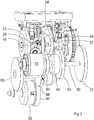
- a transmission system comprises an input shaft 10 that is connected for use to an output shaft of an engine of a vehicle.
- a front output shaft 12 is connected for use to a final drive unit at the front of a vehicle, and a rear output shaft 14 is connected for use to a final drive unit at the front of a vehicle.
- An auxiliary output shaft 16 is driven directly from the input shaft 10.
- the auxiliary output shaft 16 is used to drive ancillary components of the vehicle, such as hydraulic pump.
- a first spur gear 18 is carried on the input shaft 10.
- the transmission system includes a full-toroidal variator 20.
- the variator includes two input discs 22 and two output discs 24, each having a part-toroidal recess, whereby a toroidal cavity is formed between each input disc 22 and each output disc 24. All discs have a common rotational axis, which, in this embodiment, is coaxial with the input shaft 10, which is coupled for rotation with the input discs 22.
- Each cavity contains a set of rollers 26 that can transmit drive between the input discs 22 and the output discs 24 through a medium of traction fluid.
- the ratio R v of the speeds of the input discs 22 and the output discs 24 is dependent upon the angle of tilt of the rollers 26 with respect to the discs 22, 24.
- An output gear 28 is provided between the output discs 24 and is fixed for rotation with them.
- the transmission system further includes an epicyclic gearset 40, which, as is conventional, includes a sun wheel 42, an annulus 44, and a planet carrier 46 on which is carried a plurality of planet wheels 48.
- the sun wheel 42 is fixed for rotation with a sun wheel shaft 50.
- a second spur gear 52 Also fixed on the sun wheel shaft 50 is a second spur gear 52, the second spur gear 52 being in mesh with the first spur gear 18, with a ratio R 1 .
- a planet gear 54 is carried on, and fixed for rotation with, the planet carrier 46. The ratio of the speed of the sun wheel 42 to the planet carrier 54 will be denoted R ce .
- Third and fourth spur gears 60, 62 are carried on and fixed for rotation with a first intermediate shaft 64.
- the third spur gear 60 is in mesh with the output gear 28 of the variator 20 with a ratio R 2
- the fourth spur gear 62 is in mesh with the planet gear 54.
- the planet gear 54 drives an input gear 66 of a high-regime clutch 68 with a ratio R 3 .
- the high-regime clutch 68 can selectively connect or disconnect drive from its input gear 66 to the rear output shaft 14.
- the annulus is connected to drive a second intermediate shaft 70.
- the second intermediate shaft 70 drives an input to a low-regime clutch 72 and a reverse clutch 74.
- the low-regime clutch 72 can selectively connect or disconnect drive from the second intermediate shaft 70 to a high-regime output gear 78.
- the high-regime output gear 78 is in mesh with a fifth spur gear 80, with a ratio R 4 , that is carried on and fixed for rotation with the rear output shaft 14.
- the reverse clutch 74 can selectively connect or disconnect drive from the second intermediate shaft 70 to a reverse intermediate gear 82, which is connected through an idler gear 84 to a sixth spur gear 88, with an overall ratio R 5 that is carried on and fixed for rotation with the rear output shaft 14.
- the sixth spur gear 88 drives an input gear 90 to a front-drive clutch 92.
- the front-drive clutch 92 can selectively connect or disconnect drive from its input gear 90 to the front output shaft 12.
- the transmission can operate in three regimes: low-speed forward, reverse, and high-speed forward. Operation of the transmission in these three regimes will now be described.
- the sun wheel 42 is driven by the input shaft 10 through the first and second spur gears 18, 52 in the opposite direction to the input shaft 10.
- the first and second spur gears 18, 52 provide a reduction ratio between the input shaft 10 and the sun wheel 42.
- the planet carrier 48 is driven from the output of the variator through the third and fourth spur gears 60, 62, and the planet gear 54 in the opposite direction to the input shaft 10.
- na n p 1 ⁇ n s n p ⁇ 1 z s z a
- np and ns are, respectively, the input speeds of the planet carrier 48 and the sun wheel 42
- za and zs are, respectively, the number of teeth on the annulus 44 and the sun wheel 42.
- the low-regime clutch 72 In the low-speed forward regime, the low-regime clutch 72 is engaged, and the reverse clutch 74 and the high-regime clutch 68 are disengaged.
- the output shaft 14 is driven by the annulus 44 through the low-regime clutch 72, the high-regime output gear 78 and the fifth spur gear.
- geared neutral is achieved by suitable selection of the ratios of the first and second spur gears 18, 52; the ratios of the third and fourth spur gears 60, 62 and the planet gear 54; and the minimum ratio of the variator 20 to satisfy equation 2.
- the transmission ratio of the transmission can be varied continuously as the variator 20 is moved from the ratio at which geared neutral is achieved (the neutral low regime variator ratio) through its entire ratio spread to the maximum low-regime variator ratio, at which the transmission ratio is r low,max .
- the reverse clutch 74 In the reverse regime, the reverse clutch 74 is engaged, and the low-regime clutch 72 and the high-regime clutch 68 are disengaged.
- the output shaft 10 is driven by the annulus 44 through the reverse clutch 74, the reverse intermediate gear 82, the idler gear 84 and the sixth spur gear 88.
- the idler gear 84 serves to reverse the direction of drive to the rear output shaft 14.
- the transmission ratio in reverse is higher than in the low-speed forward regime. This is achieved by selecting the intermediate gear 82 to be larger than the high-regime output gear 78.
- the high-regime clutch 68 In the high-speed forward regime, the high-regime clutch 68 is engaged, and the reverse clutch 74 and the low-regime clutch 72 are disengaged.
- the output shaft 14 is driven from the output of the variator 20 driving through the third and fourth spur gears 60, 62; the planet gear 54, the planet gear 54 through the input gear 66 and the high-regime clutch 68.
- the annulus 44 is free to rotate, so the epicyclic gearset does not operate as part of the drive train in this regime.
- a change in the ratio of the variator 20 has a direct effect on the overall transmission ratio.
- the transmission ratio in the high-speed forward regime extends between r high,min and r high,mxz .
- the transmission can be operated in a two-wheel drive mode or a four-wheel drive mode by disengaging or engaging the front-drive clutch 92.
- the end discs 22 of the variator 20 are subject to their highest levels of contact stress as the variator ratio 20 is at a minimum and the precession angle of the rollers 26 at its highest. Time spent at this condition could have a significant detrimental impact on durability of the variator 20. If the spread of the variator ratio (and hence the transmission ratio spread) in the high-speed regime is reduced, while still having the maximum speed/transmission ratio at the maximum variator ratio, then this area of peak stress can be avoided.
- the full-toroidal variator of this embodiment In order to operate, the full-toroidal variator of this embodiment must be provided with a volume of traction fluid. While this can also be used to lubricate other components in the transmission, this is disadvantageous since traction fluid may be more expensive than conventional gear oil. Therefore, the present embodiment is constructed such that only the variator 20 operates in traction fluid, with the remaining components being separate and operating in conventional gear oil. This ensures that the amount of traction fluid required for operation of the transmission is minimised, which is advantageous in that it minimises cost. In addition, the efficiency with which gears operate in gear oil may be slightly better in gear oil than in traction fluid.
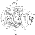
- Figure 5 shows a two-cavity full-toroidal variator suitable for use in embodiments of the invention.
- the variator has a first toroidally-recessed driving disc 110, facing which is a first toroidally recessed (the recess not being shown) driven disc 112.
- a first toroidal cavity is defined between the opposing toroidally-recessed faces of the driving and driven discs 110, 112.
- the driven disc 112 also has a second toroidal recess 111 on its opposite side providing a second toroidally recessed driven surface.
- a second toroidally-recessed driving disc 113 is provided, defining a second toroidal cavity with the second driven surface 111.
- Each of the discs 110, 112, 113 is located on a common axis, which will be referred to as the variator axis.
- the input shaft 10 is coaxial with the variator axis.
- Each of the driving discs 110, 113 is fixed to the input shaft 10 for rotation with it.
- the driven disc 112 is carried for rotation on the input shaft 10.
- First and second rollers 114, 116 are mounted in the first toroidal cavity to transmit drive from the driving disc 110 to the driven disc 112 with a variator ratio which varies as the first and second rollers 114, 116 tilt.
- Third and fourth rollers 115, 117 are mounted in the second toroidal cavity to transmit drive from the driving disc 111 to the driven disc 113 with a ratio which is variable by tilting the third and fourth rollers 115, 117.
- the first and second rollers 114, 116 are rotatably mounted in a first roller carrier 140.
- the first roller carrier 140 comprises a first roller carriage 144, 146 for the first roller 114 and a second roller carriage for the second roller 116.
- a second roller carrier 141 comprises similar roller carriages for the third and fourth rollers 115, 117.
- the rollers 114, 116 and 115, 117 are each mounted by means of a respective stub axle 142 that is rotatably mounted in a respective roller carriage, each being defined by opposed planar support plates 144, 146.
- the mounting of the rollers is numbered only on one roller for illustrative purposes and in the interests of clarity.
- the rollers 114, 116; 115, 117 are mounted on the carriers 140, 141 via spherical bearings to provide the required degrees of freedom of movement.
- the first roller carrier 140 carries the first and second rollers 114,116, and the second roller carrier 141 carries the third and fourth rollers 115,117.
- Each roller carrier 140, 141 comprises a respective cross-bar 148, 149 which links the two roller carriages within the roller carrier 140, 141.
- Each roller carriage is mounted on the cross bar 148, 149 such that it can pivot with respect to the cross bar about an axis that is normal to both the variator axis and to the axis of rotation of the stub axle 142 - that is to say, tangential to the discs 110, 112, 113.
- Each cross-bar is pivotally mounted, the pivot axis being parallel to the variator axis and normal to the axis of rotation of the rollers 114,116; 115, 117.
- Each cross-bar 148, 149 is provided with an actuating arm 160, 161 which projects in a radial direction from the variator axis in a direction generally parallel to the axis of rotation on the associated roller carriages on the cross-bars 148, 149.
- End portions of the arms 160, 161 project out of a variator housing are have recess that is C-shaped, when viewed along the variator axis, for direct mechanical engagement with a control linkage.
- the control linkage 164 comprises a linking lever 166 mounted to pivot on a pivot bearing 168 about an axis that is normal to and intersects the variator axis.
- the pivot bearing 168 is carried on an output element of an actuator 170.
- End portions of the linking lever 166, to opposite sides of its pivot axis are each received in the recess of a respective one of the arms 160, 161, whereby the linking lever 166 is operatively linked to the carriers 140, 141.
- These end portions are part-spherical in shape to enable them to move smoothly within the recesses.
- the linking lever 166 rotates about its pivot bearing 168, the arms 160, 161 move the arms 160, 161 in opposite directions in respective plane perpendicular to the variator axis. Rotation of the linking lever 166 will cease when the forces applied to it be the arms 160, 161 are equal in magnitude and opposite in direction.
- the actuator 170 is a dual-acting hydraulic actuator in this embodiment. Its output element can be caused to move in a direction tangential to the discs 110, 112, 113, carrying the linking lever 166 with it.
- the actuator 170 moves from a central position (in which the discs are rotating about an axis that is normal to the variator axis) its force is balanced by a reaction torque that acts on the rollers 114, 116; 115, 117 about the variator axis.
- the torque on the first and the second rollers 114, 116 is in a direction opposite to that of the third and the fourth rollers 115, 117. Therefore, the forces on the opposite end portions of the linking lever 166 act in opposite directions.
- the linking lever 166 will rotate until such forces are balanced, which implies that the reaction torque from one cavity will also be balanced by the reaction torque from the other cavity.
- the driven disc 112 is provided with teeth 130 on its circumference to form a spur gear, whereby drive may be taken through the third spur gear 60.
- a gear force Fg is generated which may impart a bending force to the driving shaft and cause the more distant parts of the driving surfaces 110, 113 to bow or splay away from the driven surfaces 112, 111.
- Figure 6 shows a further variator suitable for use in embodiments of the invention.
- the variator has a single cavity formed between a toroidally-recessed driving disc 110 and a facing toroidally recessed driven disc 112.
- the discs are coaxial and rotate about a variator axis.
- Two rollers 114, 116 (116 not shown) are mounted in the toroidal cavity defined between the opposing toroidally-recessed faces of the driving and driven discs 110, 112 to transmit drive from the driving disc 110 to the driven disc 112 with a ratio which is variable by tilting the rollers 114, 116.
- the rollers rotate about a common axis that will be referred to as the roller axis.
- An input shaft 10 is coaxial with the variator axis.
- the driving disc 110 is fixed to the input shaft 10 for rotation with it.
- the driven disc 112 is carried for rotation on the input shaft 10.
- the driven disc 112 is provided with teeth 130 on its circumference whereby drive is taken to the third spur gear 60.
- a gear force Fg is generated which imparts a bending moment to the input shaft 10, which causes the more distant parts of the driving surface of the driving disc 110 and the driven surface of the driven disc 112 to splay apart.
- Each roller 114, 116 contacts the driving disc 110 and driven disc 112 arranged in such a way that the force Fg is perpendicular to the two planes that pass through the roller-disc contact points when the variator is at a -1.0 ratio (that is, when the roller axis is perpendicular to the variator axis). This is achieved by ensuring that a line joining the axis of rotation of the third spur gear 60 and the variator axis is perpendicular to the roller axis.
- each disc 110, 112 the roller-disc contact points are located in a plane that passes through the neutral axis of bending of the variator. This means that the distance between the two contact points between each roller 114, 116 and the discs 110, 112 is substantially invariant wen the shaft 10 bends, and any such variation that does occur will affect each roller substantially equally. This means that the normal contact forces between the discs 110, 112 and the rollers 114, 116 are not substantially affected by the radial force Fg and each roller contact bears an equal proportion of an applied end-load force.
- the rollers 114 and 116 may each be actuated by an actuator 170 or may both be actuated by a single actuation mechanism. Hydraulic actuators may be employed to provide ratio control.
- the variator is preferably torque-controlled.
- Figure 7 shows diagrammatically a further variation on a two-cavity variator suitable for use in embodiments of the invention. As with the embodiment of Figure 5 , this variator has a driven disc 210, and first and second driving discs 201, 200. A first toroidal cavity is formed between the first driving disc 201 and the driven disc 210, and a second toroidal cavity is formed between the second driving disc 200 and the driven disc 210.
- this variator has several twin roller sets supported between driving and driven discs.
- one roller set includes first and second rollers 212 and 213, and three similar roller sets are also shown.
- Each roller has an outer surface that has two distinct regions.
- the conical region may be formed with a very large crown radius or with curved edges so as to reduce stress concentrations at the edges of the conical surface.
- Drive from the driving disc 201 is transmitted to the first roller 212 of the roller set, thence to the second roller 213 of the roller set, which then drives the driven disc 210.
- the rollers 212, 213 in the roller set are arranged such that only their spherical regions make contact with the discs and only their conical regions make contact with each other.
- each roller set the rollers are carried on a roller carrier that allows them to rotate about axes that have an angle fixed with respect to one another.
- the cone angle of the conical region, and the angle between the axis is arranged such that, when clamped together along the variator axis by the discs 201, 200, 210, the rotational axes of all of the rollers lie within a plane that passes through the variator axis but run through the variator axis 216.
- the axes are displaced from each other under the influence only of the conical surfaces and the clamping reactions,.
- the degree of displacement is such that in at least one position, each roller (not necessarily simultaneously) experiences a state where the differential velocities across the contacting surfaces is less than 0.5% and where the tangent of the disc and roller surface 210 at the centre of the point of contact, and the roller rotational axis 211, and the disc rotational axis 216 generally pass through the same point 217.
- the variator shown in Figures 9 and 10 has at least one pair of rollers.
- the rollers contact each other along a theoretical line the centre point of which is indicated by m, which line remains always perpendicular to the line AB passing through the centre-points of the contact lines of the two rollers and of each roller and its corresponding disc.
- the axes X_Y respectively of the two rollers of each pair always intersect or are concurrent and are always situated in a plane containing the variator axis CD of the driving and the driven discs.
- Figure 10 presents the predictions of a model for power losses of a conventional 5-forward/3-reverse step-change transmission driving through a torque converter, and a transmission embodying the present invention, as applied to a backhoe loader or a wheel loader.
- Vehicle roadspeed is on the x -axis and power loss on the y -axis in each gear.
- the traces labelled 1f to 5f are for the five forward speeds and the traces labelled 1r to 2r are for the three reverse speeds.
- the power loss for each individual speed in the conventional gearbox is plotted, as is the single-line plot that represents power loss using an embodiment of the invention.
- the hatched area represents the difference in power loss between the two transmission systems. This suggests that the embodiment of the invention is capable of achieving significant reduction in power losses as compared with a conventional transmission system.
- the regimes operate with the variator in a direct mode. That is, all of the power flowing through the transmission passes through the variator.
- a direct mode that is, all of the power flowing through the transmission passes through the variator.
- a power split In a first alternative, which will be referred to as a "power split", only a portion the total power passes through the variator, with the remaining following a direct mechanical path from the input to the output of the transmission, bypassing the variator.
- the epicyclic gearset is disposed between the input to the transmission and the variator.
- a portion the total power passes through the variator in a direction from the output to the input, with power in excess of the total passing through the transmission following a direct mechanical path from the input to the output of the transmission, bypassing the variator.
- the epicyclic gearset is disposed between the output of the transmission and the variator.
- embodiments of the invention might use at least powersplitting or power recirculation in the high-speed regime.
- the direction of flow of power through the direct mechanical path and the variator is in the same direction.
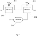
- FIG. 11 One possible arrangement of a transmission that uses power splitting is shown in Figure 11 .
- This arrangement comprises a low-speed regime epicyclic gearset 310 and a high-speed regime epicyclic gearset 312, each having an associated clutch 314, 316 that can connect the input to the output of the associated epicyclic gearset.
- This arrangement provides an epicyclic gearset on the input to the transmission when it is operating in the high-speed regime.
Landscapes
- Engineering & Computer Science (AREA)
- General Engineering & Computer Science (AREA)
- Mechanical Engineering (AREA)
- Friction Gearing (AREA)
- Transmission Devices (AREA)
Claims (13)
- Getriebe, umfassend eine Eingangswelle (10) und eine Abtriebswelle (12), wobei das Getriebe betriebsfähig ist, um einen Drehantrieb zwischen der Eingangs- und der Abtriebswelle zu übertragen, wobei das Getriebe einen Variator (20) umfasst, der den Antrieb mit einem stufenlosen Verhältnis zwischen einem minimalen Variatorverhältnis und einem maximalen Variatorverhältnis übertragen kann, welches Getriebe in einem Niedrigdrehzahl-Betriebszustand und in einem Hochdrehzahl-Vorwärtsbetriebszustand arbeiten kann, wobei das Getriebe:im Niedrigdrehzahl-Betriebszustand bei einem neutralen Variatorverhältnis mit Niedrig-Betriebszustand betriebsfähig ist, bei dem die Abtriebswelle (12) des Getriebes feststehend ist unabhängig von der Drehzahl der Eingangswelle (10) des Getriebes und bei einem maximalen Variatorverhältnis mit Niedrig-Betriebszustand, das größer ist als das neutrale Variatorverhältnis mit Niedrig-Betriebszustand, bei dem die Abtriebswelle (12) des Getriebes von der Eingangswelle (10) des Getriebes mit einem maximalen Übersetzungsverhältnis mit Niedrig-Betriebszustand angetrieben wird;dadurch gekennzeichnet, dass das Getriebe im Hochdrehzahl-Betriebszustand bei einem minimalen Variatorverhältnis mit Hoch-Betriebszustand betriebsfähig ist, bei dem die Abtriebswelle (12) des Getriebes von der Eingangswelle (10) des Getriebes bei einem minimalen Übersetzungsverhältnis mit Hoch-Betriebszustand und bei einem maximalen Variatorverhältnis mit Hoch-Betriebszustand angetrieben wird, das größer ist als das minimale Variatorverhältnis mit Hoch-Betriebszustand, bei dem die Abtriebswelle (12) des Getriebes von der Eingangswelle (10) des Getriebes bei einem maximalen Übersetzungsverhältnis mit Hoch-Betriebszustand angetrieben wird, das größer ist als das minimale Übersetzungsverhältnis mit Hoch-Betriebszustand; unddas Getriebe so konfiguriert ist, dass ein Wechsel zwischen dem Niedrigdrehzahl-Betriebszustand und dem Hochdrehzahl-Betriebszustand nicht synchron ist.
- Getriebe nach Anspruch 1, bei dem das maximale Übersetzungsverhältnis mit Niedrig-Betriebszustand im Wesentlichen gleich oder größer als das minimale Übersetzungsverhältnis mit Hoch-Betriebszustand ist.
- Getriebe nach Anspruch 1 oder Anspruch 2, ferner umfassend einen Planetengetriebesatz (40), der betriebsfähig ist, um zu ermöglichen, dass die Abtriebswelle (12) des Getriebes feststehend ist unabhängig von der Drehzahl der Eingangswelle (10) des Getriebes im Niedrigdrehzahl-Betriebszustand.
- Getriebe nach Anspruch 3, ferner umfassend eine Niedrigdrehzahlkupplung (72), die während des Betriebs im Niedrigdrehzahl-Betriebszustand eingerückt ist, um den Planetengetriebesatz (40) betriebsmäßig mit dem Variator (20) zu koppeln, und die betriebsmäßig im Hochdrehzahl-Betriebszustand ausgerückt ist, um den Planetengetriebesatz (40) betriebsmäßig von dem Variator (20) zu entkoppeln.
- Getriebe nach Anspruch 3 oder Anspruch 4, ferner umfassend eine Hochdrehzahl-Kupplung (68), die während des Betriebs im Hochdrehzahl-Betriebszustand eingerückt ist, um den Variator (20) mit der Abtriebswelle (12) des Getriebes zu koppeln, und die während des Betriebs im Niedrigdrehzahl-Betriebszustand ausgerückt ist, um den Variator (20) von der Abtriebswelle (12) des Getriebes zu entkoppeln.
- Getriebe nach einem der vorhergehenden Ansprüche, wobei das Getriebe im Hochdrehzahl-Betriebszustand nur bei einem Übersetzungsverhältnis betreibbar ist, das höher ist als das maximale Übersetzungsverhältnis mit Niedrig-Betriebszustand.
- Getriebe nach einem der vorhergehenden Ansprüche, ferner umfassend einen Zahnradsatz (82), der zumindest im Niedrigdrehzahl-Betriebszustand selektiv in einen Antriebspfad eingebunden oder von diesem getrennt werden kann, um zu bewirken, dass die Abtriebswelle (12) des Getriebes umgekehrt wird.
- Getriebe nach einem der vorhergehenden Ansprüche, bei dem im Hochdrehzahl-Betriebszustand die gesamte Leistung, die durch das Getriebe fließt, durch den Variator (20) fließt.
- Getriebe nach einem der Ansprüche 1 bis 7, bei dem im Hochdrehzahl-Betriebszustand ein Teil der durch das Getriebe fließenden Leistung den Variator (20) umgeht.
- Getriebe nach einem der vorhergehenden Ansprüche, bei dem der Variator (20) drehmomentgesteuert ist.
- Getriebe nach einem der vorhergehenden Ansprüche, bei dem der Variator (20) ein vollständiger Toroidvariator ist, optional wobei der vollständige Toroidvariator (20) zwei Hohlräume mit zwei Rollen umfasst, die in jedem Hohlraum (114, 115, 116, 117) angeordnet sind.
- Fahrzeug, umfassend ein Getriebe nach einem der vorhergehenden Ansprüche; optional, wobei das Fahrzeug betreibbar ist, um Ladevorgänge durchzuführen; optional, wobei das Fahrzeug einer von einem Tieflöffelbagger, einem Radlader oder einem Gabelstapler ist.
- Verfahren zum Durchführen eines Betriebszustandswechsels in einem Getriebe nach einem der Ansprüche 1 bis 11 oder in einem Fahrzeug nach Anspruch 12, wobei das Verfahren umfasst:Versetzen des Variatorverhältnisses in Richtung des minimalen Variatorverhältnisses, um den Betriebszustand des Getriebes zwischen dem Niedrigdrehzahl-Betriebszustand und dem Hochdrehzahl-Betriebszustand zu ändern; undBeseitigen des Drehmoments von der Eingangswelle.
Applications Claiming Priority (2)
| Application Number | Priority Date | Filing Date | Title |
|---|---|---|---|
| GBGB1214316.0A GB201214316D0 (en) | 2012-08-10 | 2012-08-10 | Infinitely-variable transmission for a vehicle |
| PCT/EP2013/066738 WO2014023832A1 (en) | 2012-08-10 | 2013-08-09 | Infinitely-variable transmission for a vehicle |
Publications (2)
| Publication Number | Publication Date |
|---|---|
| EP2882982A1 EP2882982A1 (de) | 2015-06-17 |
| EP2882982B1 true EP2882982B1 (de) | 2020-10-21 |
Family
ID=46981366
Family Applications (1)
| Application Number | Title | Priority Date | Filing Date |
|---|---|---|---|
| EP13747678.4A Not-in-force EP2882982B1 (de) | 2012-08-10 | 2013-08-09 | Stufenloses getriebe für ein fahrzeug |
Country Status (6)
| Country | Link |
|---|---|
| US (1) | US9568083B2 (de) |
| EP (1) | EP2882982B1 (de) |
| CN (1) | CN104822972B (de) |
| BR (1) | BR112015002854B1 (de) |
| GB (2) | GB201214316D0 (de) |
| WO (1) | WO2014023832A1 (de) |
Families Citing this family (17)
| Publication number | Priority date | Publication date | Assignee | Title |
|---|---|---|---|---|
| EP1954959B1 (de) | 2005-11-22 | 2013-05-15 | Fallbrook Intellectual Property Company LLC | Stufenlos verstellbares getriebe |
| CA2976893C (en) | 2005-12-09 | 2019-03-12 | Fallbrook Intellectual Property Company Llc | Continuously variable transmission |
| EP1811202A1 (de) | 2005-12-30 | 2007-07-25 | Fallbrook Technologies, Inc. | Stufenloses Getriebe |
| US8996263B2 (en) | 2007-11-16 | 2015-03-31 | Fallbrook Intellectual Property Company Llc | Controller for variable transmission |
| JP5783723B2 (ja) | 2007-12-21 | 2015-09-24 | フォールブルック インテレクチュアル プロパティー カンパニー エルエルシー | 自動変速機及びその方法 |
| US8535199B2 (en) | 2008-06-06 | 2013-09-17 | Fallbrook Intellectual Property Company Llc | Infinitely variable transmissions, continuously variable transmissions, methods, assemblies, subassemblies, and components therefor |
| CN107061653B (zh) * | 2012-01-23 | 2020-05-26 | 福博科知识产权有限责任公司 | 无限变速式无级变速器、连续变速式无级变速器、方法、组件、子组件以及其部件 |
| US10047861B2 (en) | 2016-01-15 | 2018-08-14 | Fallbrook Intellectual Property Company Llc | Systems and methods for controlling rollback in continuously variable transmissions |
| ITUA20163270A1 (it) * | 2016-05-09 | 2017-11-09 | Bosch Gmbh Robert | Gruppo di pompaggio e metodo per alimentare combustibile, preferibilmente gasolio, ad un motore a combustione interna |
| US10023266B2 (en) | 2016-05-11 | 2018-07-17 | Fallbrook Intellectual Property Company Llc | Systems and methods for automatic configuration and automatic calibration of continuously variable transmissions and bicycles having continuously variable transmissions |
| DE102016209943A1 (de) * | 2016-06-07 | 2017-12-07 | Zf Friedrichshafen Ag | Leistungsverzweigungsgetriebe |
| DE102017106907A1 (de) * | 2017-03-28 | 2018-10-04 | Ulrich Rohs | Leistungsverzweigter Antriebsstrang für eine mobile Arbeitsmaschine und Verfahren zum leistungsverzweigten Antrieb einer mobilen Arbeitsmaschine |
| US11215268B2 (en) | 2018-11-06 | 2022-01-04 | Fallbrook Intellectual Property Company Llc | Continuously variable transmissions, synchronous shifting, twin countershafts and methods for control of same |
| US11174922B2 (en) | 2019-02-26 | 2021-11-16 | Fallbrook Intellectual Property Company Llc | Reversible variable drives and systems and methods for control in forward and reverse directions |
| FR3124484B1 (fr) | 2021-06-23 | 2023-06-16 | Ifp Energies Now | Véhicule terrestre à assistance électrique avec une transmission infiniment variable inversée |
| FR3128502B1 (fr) | 2021-10-27 | 2024-01-19 | Ifp Energies Now | Transmission variable comprenant un train épicycloïdal avec des galets coniques ou tronconiques |
| FR3142788A1 (fr) | 2022-12-05 | 2024-06-07 | IFP Energies Nouvelles | Transmission variable avec galets coniques ou tronconiques et une couronne |
Family Cites Families (24)
| Publication number | Priority date | Publication date | Assignee | Title |
|---|---|---|---|---|
| JPS59110954A (ja) | 1982-12-13 | 1984-06-27 | Toyota Motor Corp | 無段変速装置 |
| GB9300862D0 (en) | 1993-01-18 | 1993-03-10 | Fellows Thomas G | Improvements in or relating to transmissions of the toroidal-race,rolling-traction type |
| DE19703544A1 (de) * | 1997-01-31 | 1998-08-06 | Zahnradfabrik Friedrichshafen | Reibradgetriebe |
| JP3711688B2 (ja) | 1997-03-22 | 2005-11-02 | マツダ株式会社 | トロイダル式無段変速機 |
| DE19836558C2 (de) * | 1997-08-12 | 2003-03-13 | Nsk Ltd | Stufenlos verstellbares Toroidgetriebesystem |
| JP3716569B2 (ja) * | 1997-08-25 | 2005-11-16 | マツダ株式会社 | 無段変速機の制御装置 |
| JP3697860B2 (ja) * | 1997-10-07 | 2005-09-21 | 日本精工株式会社 | トロイダル形無段変速装置 |
| US6059685A (en) | 1999-05-06 | 2000-05-09 | Ford Global Technologies, Inc. | Coaxial traction drive automatic transmission for automotive vehicles |
| US6045477A (en) | 1999-06-14 | 2000-04-04 | General Motors Corporation | Continuously variable multi-range powertrain with a geared neutral |
| US6561942B2 (en) | 2001-06-11 | 2003-05-13 | General Motors Corporation | Dual mode variable ratio transmission |
| GB2384835B (en) * | 2002-02-01 | 2006-02-22 | Torotrak Dev Ltd | Continuously variable transmission system |
| CA2487064C (en) * | 2002-05-28 | 2011-01-18 | Torotrak (Development) Limited | Continuously variable ratio transmission system |
| DE10315682A1 (de) * | 2003-04-07 | 2004-11-11 | Zf Friedrichshafen Ag | Allrad-Toroidgetriebe für ein Kraftfahrzeug |
| DE102004022356B3 (de) * | 2004-04-30 | 2005-12-01 | Getrag Getriebe- Und Zahnradfabrik Hermann Hagenmeyer Gmbh & Cie Kg | Toroidgetriebe |
| JP4661410B2 (ja) * | 2005-07-07 | 2011-03-30 | 株式会社エクォス・リサーチ | 無段変速機 |
| JP2007051695A (ja) * | 2005-08-18 | 2007-03-01 | Equos Research Co Ltd | 車両駆動装置 |
| GB0702490D0 (en) * | 2007-02-09 | 2007-03-21 | Torotrak Dev Ltd | CVT control system |
| GB0703351D0 (en) | 2007-02-21 | 2007-03-28 | Torotrak Dev Ltd | Continuously variable transmission |
| JP2010144906A (ja) | 2008-12-22 | 2010-07-01 | Equos Research Co Ltd | 無段変速機 |
| WO2012024225A1 (en) | 2010-08-16 | 2012-02-23 | Allison Transmission, Inc. | Gear scheme for infinitely variable transmission |
| US9109663B2 (en) * | 2010-11-15 | 2015-08-18 | Allison Transmission, Inc. | Input clutch assembly for infinitely variable transmission |
| GB201200357D0 (en) | 2012-01-10 | 2012-02-22 | Torotrak Dev Ltd | Variator |
| GB201201068D0 (en) | 2012-01-23 | 2012-03-07 | Torotrak Dev Ltd | Variator |
| GB2514294B (en) | 2012-01-23 | 2016-01-20 | Torotrak Dev Ltd | Variator |
-
2012
- 2012-08-10 GB GBGB1214316.0A patent/GB201214316D0/en not_active Ceased
-
2013
- 2013-08-09 US US14/420,520 patent/US9568083B2/en active Active
- 2013-08-09 CN CN201380053204.5A patent/CN104822972B/zh not_active Expired - Fee Related
- 2013-08-09 BR BR112015002854-3A patent/BR112015002854B1/pt not_active IP Right Cessation
- 2013-08-09 GB GB1503700.5A patent/GB2519908B/en not_active Expired - Fee Related
- 2013-08-09 WO PCT/EP2013/066738 patent/WO2014023832A1/en not_active Ceased
- 2013-08-09 EP EP13747678.4A patent/EP2882982B1/de not_active Not-in-force
Non-Patent Citations (1)
| Title |
|---|
| None * |
Also Published As
| Publication number | Publication date |
|---|---|
| GB201503700D0 (en) | 2015-04-22 |
| US9568083B2 (en) | 2017-02-14 |
| CN104822972A (zh) | 2015-08-05 |
| GB2519908B (en) | 2019-02-13 |
| EP2882982A1 (de) | 2015-06-17 |
| US20150219194A1 (en) | 2015-08-06 |
| GB201214316D0 (en) | 2012-09-26 |
| WO2014023832A1 (en) | 2014-02-13 |
| BR112015002854A2 (pt) | 2017-09-19 |
| BR112015002854B1 (pt) | 2021-12-21 |
| CN104822972B (zh) | 2019-02-12 |
| GB2519908A (en) | 2015-05-06 |
Similar Documents
| Publication | Publication Date | Title |
|---|---|---|
| US9568083B2 (en) | Infinitely-variable transmission for a vehicle | |
| US8257216B2 (en) | Infinitely variable transmission | |
| US4693134A (en) | High-powered vehicle drive train | |
| CN102575753B (zh) | 连续可变比变速器 | |
| EP3004686B1 (de) | Stufenloses planetengetriebe für 3-modus-vorderradantrieb und hinterradantrieb | |
| EP1696152B1 (de) | Stufenloses Getriebe | |
| CN101505986B (zh) | 变速传动装置 | |
| CN105065586A (zh) | 为无级变速主传动装置提供附加模式的单元 | |
| US20130210569A1 (en) | Compound planetary front wheel drive continuously variable transmission | |
| CN113389869A (zh) | 一种集齿轮-液压-菱锥为一体的多模式复合传动装置 | |
| CN102691769A (zh) | 自动变速器 | |
| CN106461032A (zh) | 变换器辅助的变速器 | |
| EP1930198B1 (de) | Übertragungsvorrichtung für geschwindigkeitsänderungen | |
| US20020187872A1 (en) | Dual mode variable ratio transmission | |
| US6422966B1 (en) | Toroidal transmission with a starting clutch | |
| KR950002991B1 (ko) | 무단 변속기 | |
| EP2547931B1 (de) | Mit einem stufenlosen getriebe ausgestatteter antriebszug | |
| KR101326368B1 (ko) | 차량 무단 변속기 | |
| JP5061647B2 (ja) | 無段変速装置 | |
| US5288281A (en) | Contiuously variable transmissions | |
| KR101326416B1 (ko) | 차량 변속기 | |
| JP4935605B2 (ja) | 無段変速機 | |
| CN114934984B (zh) | 带牵引式环面无级变速器的复合传动装置及其控制方法 | |
| KR101505739B1 (ko) | 무단 변속기 | |
| JP4840210B2 (ja) | 無段変速機 |
Legal Events
| Date | Code | Title | Description |
|---|---|---|---|
| PUAI | Public reference made under article 153(3) epc to a published international application that has entered the european phase |
Free format text: ORIGINAL CODE: 0009012 |
|
| 17P | Request for examination filed |
Effective date: 20150305 |
|
| AK | Designated contracting states |
Kind code of ref document: A1 Designated state(s): AL AT BE BG CH CY CZ DE DK EE ES FI FR GB GR HR HU IE IS IT LI LT LU LV MC MK MT NL NO PL PT RO RS SE SI SK SM TR |
|
| AX | Request for extension of the european patent |
Extension state: BA ME |
|
| DAX | Request for extension of the european patent (deleted) | ||
| 19U | Interruption of proceedings before grant |
Effective date: 20171208 |
|
| 19W | Proceedings resumed before grant after interruption of proceedings |
Effective date: 20181001 |
|
| RAP1 | Party data changed (applicant data changed or rights of an application transferred) |
Owner name: ALLISON TRANSMISSION, INC. |
|
| STAA | Information on the status of an ep patent application or granted ep patent |
Free format text: STATUS: EXAMINATION IS IN PROGRESS |
|
| 17Q | First examination report despatched |
Effective date: 20191212 |
|
| GRAP | Despatch of communication of intention to grant a patent |
Free format text: ORIGINAL CODE: EPIDOSNIGR1 |
|
| STAA | Information on the status of an ep patent application or granted ep patent |
Free format text: STATUS: GRANT OF PATENT IS INTENDED |
|
| RIN1 | Information on inventor provided before grant (corrected) |
Inventor name: GREENWOOD, CHRISTOPHER Inventor name: WINTER, PHILIP |
|
| INTG | Intention to grant announced |
Effective date: 20200603 |
|
| GRAS | Grant fee paid |
Free format text: ORIGINAL CODE: EPIDOSNIGR3 |
|
| GRAA | (expected) grant |
Free format text: ORIGINAL CODE: 0009210 |
|
| STAA | Information on the status of an ep patent application or granted ep patent |
Free format text: STATUS: THE PATENT HAS BEEN GRANTED |
|
| AK | Designated contracting states |
Kind code of ref document: B1 Designated state(s): AL AT BE BG CH CY CZ DE DK EE ES FI FR GB GR HR HU IE IS IT LI LT LU LV MC MK MT NL NO PL PT RO RS SE SI SK SM TR |
|
| REG | Reference to a national code |
Ref country code: GB Ref legal event code: FG4D |
|
| REG | Reference to a national code |
Ref country code: CH Ref legal event code: EP |
|
| REG | Reference to a national code |
Ref country code: DE Ref legal event code: R096 Ref document number: 602013073452 Country of ref document: DE |
|
| REG | Reference to a national code |
Ref country code: IE Ref legal event code: FG4D |
|
| REG | Reference to a national code |
Ref country code: AT Ref legal event code: REF Ref document number: 1326152 Country of ref document: AT Kind code of ref document: T Effective date: 20201115 |
|
| REG | Reference to a national code |
Ref country code: AT Ref legal event code: MK05 Ref document number: 1326152 Country of ref document: AT Kind code of ref document: T Effective date: 20201021 |
|
| REG | Reference to a national code |
Ref country code: NL Ref legal event code: MP Effective date: 20201021 |
|
| PG25 | Lapsed in a contracting state [announced via postgrant information from national office to epo] |
Ref country code: GR Free format text: LAPSE BECAUSE OF FAILURE TO SUBMIT A TRANSLATION OF THE DESCRIPTION OR TO PAY THE FEE WITHIN THE PRESCRIBED TIME-LIMIT Effective date: 20210122 Ref country code: FI Free format text: LAPSE BECAUSE OF FAILURE TO SUBMIT A TRANSLATION OF THE DESCRIPTION OR TO PAY THE FEE WITHIN THE PRESCRIBED TIME-LIMIT Effective date: 20201021 Ref country code: RS Free format text: LAPSE BECAUSE OF FAILURE TO SUBMIT A TRANSLATION OF THE DESCRIPTION OR TO PAY THE FEE WITHIN THE PRESCRIBED TIME-LIMIT Effective date: 20201021 Ref country code: NO Free format text: LAPSE BECAUSE OF FAILURE TO SUBMIT A TRANSLATION OF THE DESCRIPTION OR TO PAY THE FEE WITHIN THE PRESCRIBED TIME-LIMIT Effective date: 20210121 Ref country code: PT Free format text: LAPSE BECAUSE OF FAILURE TO SUBMIT A TRANSLATION OF THE DESCRIPTION OR TO PAY THE FEE WITHIN THE PRESCRIBED TIME-LIMIT Effective date: 20210222 Ref country code: NL Free format text: LAPSE BECAUSE OF FAILURE TO SUBMIT A TRANSLATION OF THE DESCRIPTION OR TO PAY THE FEE WITHIN THE PRESCRIBED TIME-LIMIT Effective date: 20201021 |
|
| REG | Reference to a national code |
Ref country code: LT Ref legal event code: MG4D |
|
| PG25 | Lapsed in a contracting state [announced via postgrant information from national office to epo] |
Ref country code: LV Free format text: LAPSE BECAUSE OF FAILURE TO SUBMIT A TRANSLATION OF THE DESCRIPTION OR TO PAY THE FEE WITHIN THE PRESCRIBED TIME-LIMIT Effective date: 20201021 Ref country code: PL Free format text: LAPSE BECAUSE OF FAILURE TO SUBMIT A TRANSLATION OF THE DESCRIPTION OR TO PAY THE FEE WITHIN THE PRESCRIBED TIME-LIMIT Effective date: 20201021 Ref country code: IS Free format text: LAPSE BECAUSE OF FAILURE TO SUBMIT A TRANSLATION OF THE DESCRIPTION OR TO PAY THE FEE WITHIN THE PRESCRIBED TIME-LIMIT Effective date: 20210221 Ref country code: SE Free format text: LAPSE BECAUSE OF FAILURE TO SUBMIT A TRANSLATION OF THE DESCRIPTION OR TO PAY THE FEE WITHIN THE PRESCRIBED TIME-LIMIT Effective date: 20201021 Ref country code: ES Free format text: LAPSE BECAUSE OF FAILURE TO SUBMIT A TRANSLATION OF THE DESCRIPTION OR TO PAY THE FEE WITHIN THE PRESCRIBED TIME-LIMIT Effective date: 20201021 Ref country code: AT Free format text: LAPSE BECAUSE OF FAILURE TO SUBMIT A TRANSLATION OF THE DESCRIPTION OR TO PAY THE FEE WITHIN THE PRESCRIBED TIME-LIMIT Effective date: 20201021 Ref country code: BG Free format text: LAPSE BECAUSE OF FAILURE TO SUBMIT A TRANSLATION OF THE DESCRIPTION OR TO PAY THE FEE WITHIN THE PRESCRIBED TIME-LIMIT Effective date: 20210121 |
|
| PG25 | Lapsed in a contracting state [announced via postgrant information from national office to epo] |
Ref country code: HR Free format text: LAPSE BECAUSE OF FAILURE TO SUBMIT A TRANSLATION OF THE DESCRIPTION OR TO PAY THE FEE WITHIN THE PRESCRIBED TIME-LIMIT Effective date: 20201021 |
|
| REG | Reference to a national code |
Ref country code: DE Ref legal event code: R097 Ref document number: 602013073452 Country of ref document: DE |
|
| PG25 | Lapsed in a contracting state [announced via postgrant information from national office to epo] |
Ref country code: RO Free format text: LAPSE BECAUSE OF FAILURE TO SUBMIT A TRANSLATION OF THE DESCRIPTION OR TO PAY THE FEE WITHIN THE PRESCRIBED TIME-LIMIT Effective date: 20201021 Ref country code: SK Free format text: LAPSE BECAUSE OF FAILURE TO SUBMIT A TRANSLATION OF THE DESCRIPTION OR TO PAY THE FEE WITHIN THE PRESCRIBED TIME-LIMIT Effective date: 20201021 Ref country code: LT Free format text: LAPSE BECAUSE OF FAILURE TO SUBMIT A TRANSLATION OF THE DESCRIPTION OR TO PAY THE FEE WITHIN THE PRESCRIBED TIME-LIMIT Effective date: 20201021 Ref country code: SM Free format text: LAPSE BECAUSE OF FAILURE TO SUBMIT A TRANSLATION OF THE DESCRIPTION OR TO PAY THE FEE WITHIN THE PRESCRIBED TIME-LIMIT Effective date: 20201021 Ref country code: CZ Free format text: LAPSE BECAUSE OF FAILURE TO SUBMIT A TRANSLATION OF THE DESCRIPTION OR TO PAY THE FEE WITHIN THE PRESCRIBED TIME-LIMIT Effective date: 20201021 Ref country code: EE Free format text: LAPSE BECAUSE OF FAILURE TO SUBMIT A TRANSLATION OF THE DESCRIPTION OR TO PAY THE FEE WITHIN THE PRESCRIBED TIME-LIMIT Effective date: 20201021 |
|
| PLBE | No opposition filed within time limit |
Free format text: ORIGINAL CODE: 0009261 |
|
| STAA | Information on the status of an ep patent application or granted ep patent |
Free format text: STATUS: NO OPPOSITION FILED WITHIN TIME LIMIT |
|
| PG25 | Lapsed in a contracting state [announced via postgrant information from national office to epo] |
Ref country code: DK Free format text: LAPSE BECAUSE OF FAILURE TO SUBMIT A TRANSLATION OF THE DESCRIPTION OR TO PAY THE FEE WITHIN THE PRESCRIBED TIME-LIMIT Effective date: 20201021 |
|
| 26N | No opposition filed |
Effective date: 20210722 |
|
| PG25 | Lapsed in a contracting state [announced via postgrant information from national office to epo] |
Ref country code: AL Free format text: LAPSE BECAUSE OF FAILURE TO SUBMIT A TRANSLATION OF THE DESCRIPTION OR TO PAY THE FEE WITHIN THE PRESCRIBED TIME-LIMIT Effective date: 20201021 Ref country code: IT Free format text: LAPSE BECAUSE OF FAILURE TO SUBMIT A TRANSLATION OF THE DESCRIPTION OR TO PAY THE FEE WITHIN THE PRESCRIBED TIME-LIMIT Effective date: 20201021 |
|
| PG25 | Lapsed in a contracting state [announced via postgrant information from national office to epo] |
Ref country code: SI Free format text: LAPSE BECAUSE OF FAILURE TO SUBMIT A TRANSLATION OF THE DESCRIPTION OR TO PAY THE FEE WITHIN THE PRESCRIBED TIME-LIMIT Effective date: 20201021 |
|
| REG | Reference to a national code |
Ref country code: CH Ref legal event code: PL |
|
| PG25 | Lapsed in a contracting state [announced via postgrant information from national office to epo] |
Ref country code: MC Free format text: LAPSE BECAUSE OF FAILURE TO SUBMIT A TRANSLATION OF THE DESCRIPTION OR TO PAY THE FEE WITHIN THE PRESCRIBED TIME-LIMIT Effective date: 20201021 |
|
| REG | Reference to a national code |
Ref country code: BE Ref legal event code: MM Effective date: 20210831 |
|
| GBPC | Gb: european patent ceased through non-payment of renewal fee |
Effective date: 20210809 |
|
| PG25 | Lapsed in a contracting state [announced via postgrant information from national office to epo] |
Ref country code: LI Free format text: LAPSE BECAUSE OF NON-PAYMENT OF DUE FEES Effective date: 20210831 Ref country code: CH Free format text: LAPSE BECAUSE OF NON-PAYMENT OF DUE FEES Effective date: 20210831 |
|
| PG25 | Lapsed in a contracting state [announced via postgrant information from national office to epo] |
Ref country code: IS Free format text: LAPSE BECAUSE OF FAILURE TO SUBMIT A TRANSLATION OF THE DESCRIPTION OR TO PAY THE FEE WITHIN THE PRESCRIBED TIME-LIMIT Effective date: 20210221 Ref country code: LU Free format text: LAPSE BECAUSE OF NON-PAYMENT OF DUE FEES Effective date: 20210809 |
|
| PG25 | Lapsed in a contracting state [announced via postgrant information from national office to epo] |
Ref country code: IE Free format text: LAPSE BECAUSE OF NON-PAYMENT OF DUE FEES Effective date: 20210809 Ref country code: GB Free format text: LAPSE BECAUSE OF NON-PAYMENT OF DUE FEES Effective date: 20210809 Ref country code: FR Free format text: LAPSE BECAUSE OF NON-PAYMENT OF DUE FEES Effective date: 20210831 Ref country code: BE Free format text: LAPSE BECAUSE OF NON-PAYMENT OF DUE FEES Effective date: 20210831 |
|
| PG25 | Lapsed in a contracting state [announced via postgrant information from national office to epo] |
Ref country code: HU Free format text: LAPSE BECAUSE OF FAILURE TO SUBMIT A TRANSLATION OF THE DESCRIPTION OR TO PAY THE FEE WITHIN THE PRESCRIBED TIME-LIMIT; INVALID AB INITIO Effective date: 20130809 |
|
| P01 | Opt-out of the competence of the unified patent court (upc) registered |
Effective date: 20230521 |
|
| PG25 | Lapsed in a contracting state [announced via postgrant information from national office to epo] |
Ref country code: CY Free format text: LAPSE BECAUSE OF FAILURE TO SUBMIT A TRANSLATION OF THE DESCRIPTION OR TO PAY THE FEE WITHIN THE PRESCRIBED TIME-LIMIT Effective date: 20201021 |
|
| PGFP | Annual fee paid to national office [announced via postgrant information from national office to epo] |
Ref country code: DE Payment date: 20230829 Year of fee payment: 11 |
|
| PG25 | Lapsed in a contracting state [announced via postgrant information from national office to epo] |
Ref country code: MK Free format text: LAPSE BECAUSE OF FAILURE TO SUBMIT A TRANSLATION OF THE DESCRIPTION OR TO PAY THE FEE WITHIN THE PRESCRIBED TIME-LIMIT Effective date: 20201021 |
|
| PG25 | Lapsed in a contracting state [announced via postgrant information from national office to epo] |
Ref country code: MT Free format text: LAPSE BECAUSE OF FAILURE TO SUBMIT A TRANSLATION OF THE DESCRIPTION OR TO PAY THE FEE WITHIN THE PRESCRIBED TIME-LIMIT Effective date: 20201021 |
|
| REG | Reference to a national code |
Ref country code: DE Ref legal event code: R119 Ref document number: 602013073452 Country of ref document: DE |
|
| PG25 | Lapsed in a contracting state [announced via postgrant information from national office to epo] |
Ref country code: DE Free format text: LAPSE BECAUSE OF NON-PAYMENT OF DUE FEES Effective date: 20250301 |
|
| PG25 | Lapsed in a contracting state [announced via postgrant information from national office to epo] |
Ref country code: TR Free format text: LAPSE BECAUSE OF FAILURE TO SUBMIT A TRANSLATION OF THE DESCRIPTION OR TO PAY THE FEE WITHIN THE PRESCRIBED TIME-LIMIT Effective date: 20201021 |