EP2881576A1 - Dispositif de distribution de gaz d'échappement recirculés, collecteur d'admission et module d'admission correspondants - Google Patents
Dispositif de distribution de gaz d'échappement recirculés, collecteur d'admission et module d'admission correspondants Download PDFInfo
- Publication number
- EP2881576A1 EP2881576A1 EP14195476.8A EP14195476A EP2881576A1 EP 2881576 A1 EP2881576 A1 EP 2881576A1 EP 14195476 A EP14195476 A EP 14195476A EP 2881576 A1 EP2881576 A1 EP 2881576A1
- Authority
- EP
- European Patent Office
- Prior art keywords
- exhaust gas
- recirculated exhaust
- flow
- air
- control member
- Prior art date
- Legal status (The legal status is an assumption and is not a legal conclusion. Google has not performed a legal analysis and makes no representation as to the accuracy of the status listed.)
- Granted
Links
Images
Classifications
-
- F—MECHANICAL ENGINEERING; LIGHTING; HEATING; WEAPONS; BLASTING
- F02—COMBUSTION ENGINES; HOT-GAS OR COMBUSTION-PRODUCT ENGINE PLANTS
- F02M—SUPPLYING COMBUSTION ENGINES IN GENERAL WITH COMBUSTIBLE MIXTURES OR CONSTITUENTS THEREOF
- F02M26/00—Engine-pertinent apparatus for adding exhaust gases to combustion-air, main fuel or fuel-air mixture, e.g. by exhaust gas recirculation [EGR] systems
- F02M26/65—Constructional details of EGR valves
- F02M26/70—Flap valves; Rotary valves; Sliding valves; Resilient valves
-
- F—MECHANICAL ENGINEERING; LIGHTING; HEATING; WEAPONS; BLASTING
- F02—COMBUSTION ENGINES; HOT-GAS OR COMBUSTION-PRODUCT ENGINE PLANTS
- F02M—SUPPLYING COMBUSTION ENGINES IN GENERAL WITH COMBUSTIBLE MIXTURES OR CONSTITUENTS THEREOF
- F02M26/00—Engine-pertinent apparatus for adding exhaust gases to combustion-air, main fuel or fuel-air mixture, e.g. by exhaust gas recirculation [EGR] systems
- F02M26/02—EGR systems specially adapted for supercharged engines
- F02M26/09—Constructional details, e.g. structural combinations of EGR systems and supercharger systems; Arrangement of the EGR and supercharger systems with respect to the engine
-
- F—MECHANICAL ENGINEERING; LIGHTING; HEATING; WEAPONS; BLASTING
- F02—COMBUSTION ENGINES; HOT-GAS OR COMBUSTION-PRODUCT ENGINE PLANTS
- F02M—SUPPLYING COMBUSTION ENGINES IN GENERAL WITH COMBUSTIBLE MIXTURES OR CONSTITUENTS THEREOF
- F02M26/00—Engine-pertinent apparatus for adding exhaust gases to combustion-air, main fuel or fuel-air mixture, e.g. by exhaust gas recirculation [EGR] systems
- F02M26/12—Engine-pertinent apparatus for adding exhaust gases to combustion-air, main fuel or fuel-air mixture, e.g. by exhaust gas recirculation [EGR] systems characterised by means for attaching parts of an EGR system to each other or to engine parts
-
- F—MECHANICAL ENGINEERING; LIGHTING; HEATING; WEAPONS; BLASTING
- F02—COMBUSTION ENGINES; HOT-GAS OR COMBUSTION-PRODUCT ENGINE PLANTS
- F02M—SUPPLYING COMBUSTION ENGINES IN GENERAL WITH COMBUSTIBLE MIXTURES OR CONSTITUENTS THEREOF
- F02M26/00—Engine-pertinent apparatus for adding exhaust gases to combustion-air, main fuel or fuel-air mixture, e.g. by exhaust gas recirculation [EGR] systems
- F02M26/13—Arrangement or layout of EGR passages, e.g. in relation to specific engine parts or for incorporation of accessories
- F02M26/17—Arrangement or layout of EGR passages, e.g. in relation to specific engine parts or for incorporation of accessories in relation to the intake system
- F02M26/19—Means for improving the mixing of air and recirculated exhaust gases, e.g. venturis or multiple openings to the intake system
-
- F—MECHANICAL ENGINEERING; LIGHTING; HEATING; WEAPONS; BLASTING
- F02—COMBUSTION ENGINES; HOT-GAS OR COMBUSTION-PRODUCT ENGINE PLANTS
- F02M—SUPPLYING COMBUSTION ENGINES IN GENERAL WITH COMBUSTIBLE MIXTURES OR CONSTITUENTS THEREOF
- F02M26/00—Engine-pertinent apparatus for adding exhaust gases to combustion-air, main fuel or fuel-air mixture, e.g. by exhaust gas recirculation [EGR] systems
- F02M26/13—Arrangement or layout of EGR passages, e.g. in relation to specific engine parts or for incorporation of accessories
- F02M26/17—Arrangement or layout of EGR passages, e.g. in relation to specific engine parts or for incorporation of accessories in relation to the intake system
- F02M26/21—Arrangement or layout of EGR passages, e.g. in relation to specific engine parts or for incorporation of accessories in relation to the intake system with EGR valves located at or near the connection to the intake system
-
- F—MECHANICAL ENGINEERING; LIGHTING; HEATING; WEAPONS; BLASTING
- F02—COMBUSTION ENGINES; HOT-GAS OR COMBUSTION-PRODUCT ENGINE PLANTS
- F02M—SUPPLYING COMBUSTION ENGINES IN GENERAL WITH COMBUSTIBLE MIXTURES OR CONSTITUENTS THEREOF
- F02M26/00—Engine-pertinent apparatus for adding exhaust gases to combustion-air, main fuel or fuel-air mixture, e.g. by exhaust gas recirculation [EGR] systems
- F02M26/13—Arrangement or layout of EGR passages, e.g. in relation to specific engine parts or for incorporation of accessories
- F02M26/22—Arrangement or layout of EGR passages, e.g. in relation to specific engine parts or for incorporation of accessories with coolers in the recirculation passage
- F02M26/23—Layout, e.g. schematics
- F02M26/27—Layout, e.g. schematics with air-cooled heat exchangers
-
- F—MECHANICAL ENGINEERING; LIGHTING; HEATING; WEAPONS; BLASTING
- F02—COMBUSTION ENGINES; HOT-GAS OR COMBUSTION-PRODUCT ENGINE PLANTS
- F02M—SUPPLYING COMBUSTION ENGINES IN GENERAL WITH COMBUSTIBLE MIXTURES OR CONSTITUENTS THEREOF
- F02M35/00—Combustion-air cleaners, air intakes, intake silencers, or induction systems specially adapted for, or arranged on, internal-combustion engines
- F02M35/10—Air intakes; Induction systems
- F02M35/10209—Fluid connections to the air intake system; their arrangement of pipes, valves or the like
- F02M35/10222—Exhaust gas recirculation [EGR]; Positive crankcase ventilation [PCV]; Additional air admission, lubricant or fuel vapour admission
-
- F—MECHANICAL ENGINEERING; LIGHTING; HEATING; WEAPONS; BLASTING
- F02—COMBUSTION ENGINES; HOT-GAS OR COMBUSTION-PRODUCT ENGINE PLANTS
- F02M—SUPPLYING COMBUSTION ENGINES IN GENERAL WITH COMBUSTIBLE MIXTURES OR CONSTITUENTS THEREOF
- F02M35/00—Combustion-air cleaners, air intakes, intake silencers, or induction systems specially adapted for, or arranged on, internal-combustion engines
- F02M35/10—Air intakes; Induction systems
- F02M35/10242—Devices or means connected to or integrated into air intakes; Air intakes combined with other engine or vehicle parts
- F02M35/10268—Heating, cooling or thermal insulating means
Definitions
- the present invention relates to the general field of air supply of motor vehicle engines, and more particularly to engines whose supply air comes from a compressor or a turbocharger.
- the invention more particularly relates to multicylinder engines and devices used to distribute recirculated exhaust gas streams to the cylinders.
- the motors concerned by the invention can be spark ignition or compression ignition (diesel engine).
- the engines can be supercharged or powered at atmospheric pressure.
- a motor vehicle engine has a combustion chamber, generally formed by a plurality of cylinders, in which a mixture of oxidant and fuel is burned to generate the engine work.
- the gases admitted into the combustion chamber are called intake gases. They include air that is called supercharging air when it comes from a compressor.
- RAS charge air cooler
- exhaust gases In order to reduce the polluting emissions, it is known to introduce into the flow of intake gas, so-called “recirculated” exhaust gases, known to those skilled in the art under the abbreviation “EGR” corresponding to “Exhaust Gas recirculation. This is exhaust gas taken downstream of the combustion chamber to be re-routed (recirculated) to the intake gas stream, upstream of the combustion chamber, where they are mixed with the charge air for admission to the combustion chamber.
- EGR exhaust Gas corresponding to "Exhaust Gas recirculation.
- an intake manifold intended to be mounted on the cylinder head of the engine allows the possible mixing of the fresh air flow and the flow of recirculated exhaust gas, and the distribution of the mixture in the cylinder head.
- recirculated exhaust gas conveying means are provided in the intake manifold for the distributed injection of the recirculated exhaust gas into the supercharging air stream.
- the recirculated exhaust gas is introduced into the intake manifold via a distribution channel arranged transversely to the flow of the charge air, opening for example through downstream of the charge air cooler and having a few injection holes which allow the recirculated exhaust gas to flow into the volume of the intake manifold.
- the recirculated exhaust gas can mix with the intake gases from, for example, the charge air cooler. The mixture is then directed to outlet channels to feed the cylinder (s) of the engine.
- the size and position of the injection holes are fixed. Indeed, the size and the arrangement of the holes are predefined for a certain operating range of the engine and can not be modified during engine operation.
- injection holes having a certain diameter make it possible to obtain an exhaust gas rate in the cylinders that satisfies for an engine speed around 1250 rpm.
- the rate of exhaust gas recirculated in the cylinders is not satisfactory for an engine speed around 2000rpm. The opposite is also valid.
- the subject of the invention is a recirculated exhaust gas distribution device of an intake manifold for an intake module of air configured to supply at least one cylinder of an internal combustion engine, an air stream comprising intake gases and / or recirculated exhaust gas, the distribution device comprising a gas distribution channel recirculated exhaust, the distribution channel comprising a first exhaust gas injection means recirculated in the air flow for supplying at least one cylinder, characterized in that the dispensing device further comprises a control member arranged in the distribution channel and configured to modulate the flow of recirculated exhaust gas injected by the first injection means.
- Such a distribution device optimizes the distribution of recirculated exhaust gas for several operating points of the engine, for example for a range of engine speed of the order of 1250 to 2500 rpm.
- control member allows an active modulation of the recirculated exhaust gas flow injected into the supercharging air flow, by modifying the passage section of the recirculated exhaust gas flow injected by the first d injection into the supercharging air flow in particular depending on the engine conditions.
- control member is rotatable and is configured to modulate the flow of recirculated exhaust gas as a function of the angular position of the rotary control member. It may be for example a rotary plug, or a rotary flap, such as a butterfly-type flap.
- control member is movable in translation. It may be for example a mobile flap in translation of the guillotine type.
- the first injection means comprises at least one first injection hole and the control member is shaped so as to adjust the dimensions of the first injection hole.
- the control member makes it possible to vary the size or size of the first injection holes as a function of the engine speed, and consequently allows a precise exhaust gas distribution according to different engine conditions.
- the invention also relates to an intake manifold for an air intake module configured for supplying at least one cylinder of an internal combustion engine, by an air stream comprising intake gases and / or combustion gases.
- recirculated exhaust characterized in that it comprises at least one recirculated exhaust gas distribution device as defined above.
- the invention also relates to an air intake module, such as supercharging air, configured to supply at least one cylinder of an internal combustion engine, by an air flow comprising intake gases and / or or recirculated exhaust gas (EGR), characterized in that it comprises at least one recirculated exhaust gas distribution device as defined above.
- an air intake module such as supercharging air
- EGR recirculated exhaust gas
- the air intake module comprises a heat exchanger configured to condition the flow of air, and an intake manifold configured to supply at least one cylinder of the engine arranged downstream of the heat exchanger. according to the flow direction of the air flow in the intake module.
- the recirculated exhaust gas distribution device is arranged downstream of the heat exchanger, on a portion upstream of the intake manifold, with respect to the direction of flow of the air flow in the intake module.
- an intake module 1 intended to be placed on the cylinder head of a multicylinder engine (not shown in the figures) and which comprises for each cylinder of the engine at least one duct intended to extend in the cylinder head to supply the cylinder with gas intake.
- the intake module 1 comprises an intake manifold 3, also called distribution manifold, in which opens (s) the (s) supply duct (s) of the engine cylinders.
- the intake manifold 3 is configured to distribute the flow of intake gas between the ducts respectively associated with a cylinder of the engine according to the illustrated example.
- the intake module 1 further comprises an inlet manifold 5 for supplying the intake manifold 3 with inlet gas.
- the intake module 1 may comprise a heat exchanger 7 through which the inlet gas from the inlet manifold 5 passes before being distributed in the supply ducts of the different cylinders.
- the heat exchanger 7 is configured to cool the charge air.
- Such a heat exchanger 7 is generally called a charge air cooler, known by the abbreviation "RAS”.
- RAS charge air cooler
- Such a heat exchanger 7 may comprise a bundle of tubes or plates (not shown) delimiting fluid flow channels, such as the coolant, and has at least one inlet and outlet manifold 9 for the coolant.
- the terms “upstream” and “downstream” are defined with respect to the direction of circulation of the charge air in the intake module 1.
- the charge air is introduced into the heat exchanger 7 through the inlet manifold 5, mounted upstream of the heat exchanger 7, and discharged through the intake manifold 3, also called distribution manifold, mounted in downstream of the heat exchanger 7 and intended to be connected to the cylinder head of the engine (not shown).
- the intake manifold 3 allows a distributed admission into the engine cylinders of the intake gases and / or recirculated exhaust gases.
- the intake manifold 3 is for example metal and can be mounted on the cylinder head of the engine (not shown).
- the intake manifold 3 comprises at least one outlet channel 10 forming a passage section for the charge air.
- air fresh air fresh air possibly mixed exhaust gas recovered at the engine output.
- the intake manifold 3, mounted downstream of the heat exchanger 7, comprises an open upstream portion on which opens the exit face of the beam of the heat exchanger 7, and a downstream portion intended to be fixed on the cylinder head of the engine.
- the downstream portion of the intake manifold 3 here comprises the outlet channel (s) 10 arranged to open respectively into the intake cylinders of the engine.
- the intake manifold 3 further comprises a distribution device 11 of the recirculated exhaust gas.
- the dispensing device 11 is at the level of the upstream portion of the intake manifold 3.
- the dispensing device 11 allows injection of the recirculated exhaust gas into the supercharging air stream.
- the distribution device 11 comprises an exhaust gas distribution channel 13 and a first exhaust gas injection means 15, such as at least one first injection hole 15, for putting into fluid communication the distribution channel 13 and the outlet channel (s) 10 for feeding the cylinders.
- the distribution channel 13 is arranged on the upstream portion of the intake manifold 3.
- the distribution channel 13 extends in the example illustrated on the figures 2 and 3 facing the outlet of the heat exchanger 7, substantially transversely to the direction of flow of the charge air.
- the distribution channel 13 extends here over the entire width of the intake manifold 3.
- It may be a distribution channel 13 of substantially cylindrical shape.
- the first or the first injection holes 15 are, for example, made on a wall of the distribution channel 13 downstream with respect to the direction of circulation of the charge air.
- the distribution channel 13 comprises a series of first injection holes 15, here four first injection holes 15.
- the first injection holes 15 are, for example, substantially circular. They could also be oval or any other suitable forms.
- the intake manifold 3 may have a number of different first injection holes 15.
- another shape or dimensions of the first different injection holes 15 may be provided.
- the dispensing device 11 further comprises a control member 17 configured to modulate the recirculated exhaust gas stream which is injected by the first injection means 15.
- control member 17 is here shaped so as to vary the dimensions of the first injection holes 15.
- control 17 is shaped to adjust the diameter of the first injection holes 15.
- the dimensions, in particular the diameter, of the first injection holes 15 are related to the engine speed.
- the control member makes it possible to adjust the dimensions of the first injection holes 15 as a function of the engine speed.
- the control member 17 may be driven by an actuator 18 which may be electrical or alternatively pneumatic.
- an electric actuator 18 it is possible to provide a continuous fine adjustment of the position, for example angular, of the control member 17 with a very small amplitude of movement.
- a pneumatic actuator 18 it is possible, for example, to provide a predefined number of angular positions of the control member 17.
- control member 17 may be driven by the motor shaft.
- control member 17 is movable in translation.
- a movable control flap in translation such as a guillotine type flap.
- control member 17 is made in the form of a substantially cylindrical rotary tube called plug.
- a rotary control member such as a rotary flap, for example a butterfly-type flap.
- the plug 17 is configured to rotate about its longitudinal axis.
- the plug 17 is adapted to be arranged so that its longitudinal axis is arranged substantially transversely to the direction of flow of the charge air.
- the plug 17 is arranged in the distribution channel 13 so as to extend facing the outlet of the heat exchanger 7, substantially transversely to the direction of flow of the charge air.
- the plug 17 may extend over the entire length of the distribution channel 13 and thus here over the entire width of the intake manifold 3.
- the plug 17 here comprises a port 19 for entering the exhaust gas recirculated into the plug 17.
- the introduction of the exhaust gas into the plug 17 is shown schematically by the arrow EGR on the figure 2 .
- the plug 17 is shaped so as to allow or block the circulation of the recirculated exhaust gas, but also to modulate the flow of exhaust gas, in particular by adjusting the passage section of the first injection holes 15, depending on the angular position of the bushel 17.
- the plug 17 comprises a second injection means 21, such as at least one second injection hole 21.
- the second injection means 21 is shaped so as to make it possible to vary / adjust the flow section of the flow of exhaust gas recirculated by the first injection means 15.
- the plug 17 comprises a series of second injection holes 21, more precisely of the same number as the first injection holes 15, here four.
- the plug 17 has on the same side the series of second injection holes 21, four holes according to the illustrated example.
- the second injection holes 21 allow, when they are at least partially vis-à-vis the first injection holes 15, the injection of the exhaust gas into the supercharging air stream.
- the plug 17 is adapted to be arranged in a position allowing fluid communication between a first injection hole 15 and a second injection hole 21 associated.
- each second injection hole 21 is arranged on the plug 17 so as to be aligned with a first associated injection hole 15 as a function of the position of the plug 17, as illustrated in FIG. figures 2 and 3 , that is to say, so that the first and second holes 15, 21 associated injection are vis-à-vis allowing the passage of an exhaust gas flow.
- the passage is maximum for the recirculated exhaust gas stream.
- the second injection holes 21 have a substantially circular shape.
- second injection holes 21 may vary. It is also possible to provide a shape or dimensions of the second different injection holes. It is also possible to provide a different distribution of the second injection holes 21 on the plug 17. In particular, the second injection holes 21 may not be aligned with respect to each other.
- the injection of the exhaust gas is distributed thanks to the distribution of the first injection holes 15 along the distribution channel 13 and the distribution of the second injection holes 21 along the plug 17.
- the intake gases admitted by the upstream face of the intake manifold 3 mix with the gases recirculated exhaust pipe admitted by the dispensing device 11.
- the charge air comprising fresh air possibly mixed with recirculated exhaust gas is then distributed in the outlet channels 10 in order to supply the engine cylinders with gas for combustion.
- the dispensing device 11 may furthermore comprise at least one sealing means 23 arranged in such a way as to prevent a flow of recirculated exhaust gas injected via a second injection hole 21 from circulating again to another second injection hole 21 of the plug 17 instead of circulating in the volume of the intake manifold 3 to be directed to the outlet channels 10.
- this predefined position may be such that the second injection holes 21 of the plug 17 coincide with the first injection holes 15 of the distribution channel 13 or, on the contrary, such that the second injection holes 21 of the plug 17 are not aligned with the first injection holes 15 of the distribution channel 13.
- the distribution device 11 allows an active distribution of the recirculated exhaust gas, in other words allows active adaptation of the exhaust gas streams recirculated by the first injection means 15, according to the flow rate of the recirculated exhaust gas. arriving at the gas inlet 9.
- the passage section of the recirculated exhaust gas flow can be adjusted according to the speed or flow rate of the recirculated exhaust gas.
- the passage section for the gas defined by the first injection hole 15 closest to the gas inlet orifice 19 may be decreased so as to force the exhaust gas towards the other first injection holes 15 farther from the gas inlet port 19.
- the first injection hole 15 in the case of low flow of the recirculated exhaust gas, the first injection hole 15 must have a smaller diameter relative to the other first injection holes 15. To do this, in the case of a rotary plug 17, the plug 17 is rotated to a corresponding angular position.
- the first injection hole 15 closest to the gas inlet port 19 may be bypassed, the exhaust gas flowing towards the injection holes 15 farther from the gas inlet port 19.
- the passage section for the gas defined by the first injection hole 15 closest to the gas inlet port 19 can be increased so as to force the passage of the exhaust gas through this first injection hole 15 closest to the gas inlet port 19.
- the first injection hole 15 must have a larger diameter relative to the other first injection holes 15. To do this, in the case of a rotary plug 17, the plug 17 is rotated to a corresponding angular position .
- a computer in the vehicle can for example detect the flow rate of the recirculated exhaust gas and send a corresponding instruction to the actuator 18 to drive the control member 17 in the appropriate position to vary the diameter of the first injection holes 15.
- the distribution device 11 can be connected directly to an exhaust gas routing pipe 25 recovered at the motor output.
Landscapes
- Engineering & Computer Science (AREA)
- Chemical & Material Sciences (AREA)
- Combustion & Propulsion (AREA)
- Mechanical Engineering (AREA)
- General Engineering & Computer Science (AREA)
- Exhaust-Gas Circulating Devices (AREA)
Abstract
Description
- La présente invention concerne le domaine général de l'alimentation en air des moteurs de véhicules automobiles, et plus particulièrement des moteurs dont l'air d'alimentation provient d'un compresseur ou d'un turbocompresseur. L'invention vise plus particulièrement les moteurs multicylindres et les dispositifs utilisés pour distribuer les flux de gaz d'échappement recirculés vers les cylindres.
- Les moteurs concernés par l'invention peuvent être à allumage commandé ou à allumage par compression (moteur Diesel). Les moteurs peuvent être suralimentés ou alimentés à la pression atmosphérique.
- Un moteur thermique de véhicule automobile comporte une chambre de combustion, généralement formée par une pluralité de cylindres, dans laquelle un mélange de comburant et de carburant est brûlé pour générer le travail du moteur. Les gaz admis dans la chambre de combustion sont dénommés gaz d'admission. Ils comportent de l'air que l'on nomme air de suralimentation lorsqu'il provient d'un compresseur.
- Afin d'augmenter la densité de l'air de suralimentation, ces gaz sont généralement refroidis avant d'être introduits dans la chambre de combustion. Cette fonction est remplie par un échangeur thermique, également appelé refroidisseur d'air de suralimentation connu sous l'abréviation « RAS ».
- Afin de réduire les émissions polluantes, il est connu d'introduire dans le flux de gaz d'admission, des gaz d'échappement dit « recirculés », connus de l'homme du métier sous le sigle anglais « EGR » correspondant à « Exhaust Gas recirculation ». Il s'agit de gaz d'échappement prélevés en aval de la chambre de combustion pour être réacheminés (recirculés) vers le flux de gaz d'admission, en amont de la chambre de combustion, où ils sont mélangés à l'air de suralimentation en vue de leur admission dans la chambre de combustion.
- En vue de l'admission dans la culasse d'un moteur thermique de véhicule automobile d'un flux d'air de suralimentation comprenant un flux de gaz d'admission c'est-à-dire d'air frais et/ou un flux de gaz d'échappement recirculés, un collecteur d'admission destiné à être monté sur la culasse du moteur permet l'éventuel mélange du flux d'air frais et du flux de gaz d'échappement recirculés, et la répartition du mélange dans la culasse.
- Dans ce cas, on prévoit des moyens d'acheminement de gaz d'échappement recirculés dans le collecteur d'admission permettant l'injection répartie des gaz d'échappement recirculés dans le flux d'air de suralimentation.
- Selon une solution connue, les gaz d'échappement recirculés dits gaz EGR sont introduits dans le collecteur d'admission par l'intermédiaire d'un canal de distribution agencé de façon transversale à l'écoulement de l'air de suralimentation débouchant par exemple en aval du refroidisseur d'air de suralimentation et présentant quelques trous d'injection qui permettent au gaz d'échappement recirculés de s'écouler dans le volume du collecteur d'admission.
- Les gaz d'échappement recirculés peuvent se mélanger avec les gaz d'admission provenant par exemple du refroidisseur d'air de suralimentation. Le mélange est alors dirigé vers des canaux de sortie pour alimenter le(s) cylindre(s) du moteur.
- Cependant, la taille et la position des trous d'injection sont fixes. En effet, la taille et la disposition des trous sont prédéfinis pour une certaine plage de fonctionnement du moteur et ne peut être modifié pendant le fonctionnement du moteur.
- À titre d'exemple, des trous d'injection présentant un certain diamètre permettent d'obtenir un taux de gaz d'échappement dans les cylindres satisfaisant pour un régime moteur autour de 1250tr/min. Toutefois, avec ce même diamètre le taux de gaz d'échappement recirculés dans les cylindres n'est pas satisfaisant pour un régime moteur autour de 2000tr/min. L'inverse est également valable.
- En conclusion, il est nécessaire de choisir une taille qui correspond bien pour une plage de régime, mais pas pour les autres. Cela conduit à une répartition optimale limitée à une étroite plage de fonctionnement du moteur.
- À cet effet, l'invention a pour objet un dispositif de distribution de gaz d'échappement recirculés d'un collecteur d'admission pour un module d'admission d'air configuré pour alimenter au moins un cylindre de moteur à combustion interne, par un flux d'air comprenant des gaz d'admission et/ou des gaz d'échappement recirculés, le dispositif de distribution comportant un canal de distribution de gaz d'échappement recirculés, le canal de distribution comprenant un premier moyen d'injection de gaz d'échappement recirculés dans le flux d'air pour alimenter au moins un cylindre,
caractérisé en ce que le dispositif de distribution comporte en outre un organe de contrôle agencé dans le canal de distribution et configuré pour moduler le flux de gaz d'échappement recirculés injecté par le premier moyen d'injection. - Un tel dispositif de distribution permet d'optimiser la distribution de gaz d'échappement recirculés pour plusieurs points de fonctionnement du moteur, par exemple pour une plage de régime moteur de l'ordre de 1250 à 2500 tr/min.
- En effet, l'organe de contrôle permet une modulation active du flux de gaz d'échappement recirculés injecté dans le flux d'air de suralimentation, en modifiant la section de passage du flux de gaz d'échappement recirculés injectés par le premier moyen d'injection dans le flux d'air de suralimentation notamment en fonction des conditions du moteur.
- Selon un mode de réalisation, l'organe de contrôle est rotatif et est configuré pour moduler le flux de gaz d'échappement recirculés en fonction de la position angulaire de l'organe de contrôle rotatif. Il peut s'agir par exemple d'un boisseau rotatif, ou d'un volet rotatif, tel qu'un volet de type papillon.
- Selon une variante de réalisation, l'organe de contrôle est mobile en translation. Il peut s'agir par exemple d'un volet mobile en translation de type guillotine.
- Selon un aspect de l'invention, le premier moyen d'injection comporte au moins un premier trou d'injection et l'organe de contrôle est conformé de manière à ajuster les dimensions du premier trou d'injection.
- L'organe de contrôle permet de faire varier la taille ou dimension des premiers trous d'injection en fonction du régime moteur, et par conséquent permet une distribution de gaz d'échappement précise selon différentes conditions du moteur.
- Avec un tel organe de contrôle il est également possible d'obturer complètement les premiers trous d'injection, et donc d'éviter tout écoulement de gaz d'échappement recirculés dans le trajet de l'air frais.
- Il est alors possible d'éliminer la vanne de distribution de gaz d'échappement prévue dans les solutions de l'art antérieur permettant le dosage de gaz d'échappement introduit dans le canal de distribution. Il n'est donc plus nécessaire de prévoir au niveau du collecteur d'admission une interface de connexion du canal de distribution à une telle vanne. Il en résulte une réduction des coûts.
- Ledit dispositif de distribution peut en outre comporter une ou plusieurs caractéristiques suivantes, prises séparément ou en combinaison :
- l'organe de contrôle comporte un deuxième moyen d'injection de gaz d'échappement recirculés comprenant au moins un deuxième trou d'injection, et l'organe de contrôle est apte à être agencé dans une position permettant la mise en communication fluidique entre un premier trou d'injection et un deuxième trou d'injection associés, l'organe de contrôle étant par exemple un boisseau rotatif,
- le nombre de deuxièmes trous d'injection de l'organe de contrôle est le même que le nombre de premiers trous d'injection,
- le canal de distribution est apte à être agencé sensiblement transversalement par rapport à l'écoulement du flux d'air dans le module d'admission,
- l'organe de contrôle est apte à être agencé sensiblement transversalement par rapport à l'écoulement du flux d'air dans le module d'admission,
- l'organe de contrôle est réalisé sous forme d'un tube sensiblement cylindrique, tel qu'un boisseau,
- ledit dispositif comprend au moins un moyen de rappel agencé de manière à solliciter l'organe de contrôle vers une position prédéfinie de sécurité. Il peut s'agir par exemple d'un ressort de rappel.
- L'invention concerne aussi un collecteur d'admission pour un module d'admission d'air configuré pour alimenter au moins un cylindre de moteur à combustion interne, par un flux d'air comprenant des gaz d'admission et/ou des gaz d'échappement recirculés (EGR), caractérisé en ce qu'il comporte au moins un dispositif de distribution de gaz d'échappement recirculés tel que défini précédemment.
- L'invention concerne également un module d'admission d'air, tel que de l'air de suralimentation, configuré pour alimenter au moins un cylindre de moteur à combustion interne, par un flux d'air comprenant des gaz d'admission et/ou des gaz d'échappement recirculés (EGR), caractérisé en qu'il comporte au moins un dispositif de distribution de gaz d'échappement recirculés tel que défini précédemment.
- Selon un mode de réalisation, le module d'admission d'air comprend un échangeur thermique configuré pour conditionner le flux d'air, et un collecteur d'admission configuré pour alimenter au moins un cylindre du moteur agencé en aval de l'échangeur thermique selon le sens d'écoulement du flux d'air dans le module d'admission. Le dispositif de distribution de gaz d'échappement recirculés est agencé en aval de l'échangeur thermique, sur une partie en amont du collecteur d'admission, par rapport au sens d'écoulement du flux d'air dans le module d'admission.
- D'autres avantages et caractéristiques apparaîtront à la lecture de la description d'un exemple illustratif mais non limitatif de la présente invention, ainsi que des dessins annexés sur lesquels :
- la
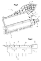
figure 1 montre un module d'admission d'air équipé d'un dispositif de distribution de gaz d'échappement selon l'invention, - la
figure 2 est une vue schématique représentant un collecteur d'admission du module d'admission de lafigure 1 , comprenant un dispositif de distribution de gaz d'échappement, et - la
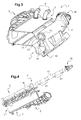
figure 3 est une vue en coupe du module d'admission, - la
figure 4 est une vue éclatée du collecteur d'admission et d'un organe rotatif de contrôle des flux de gaz d'échappement, et - la
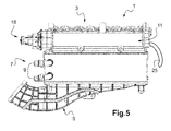
figure 5 est une vue du module d'admission représentant de façon schématique la connexion fluidique entre l'organe rotatif de contrôle et une canalisation d'acheminement de gaz d'échappement recirculés. - Dans ces figures, les éléments sensiblement identiques portent les mêmes références.
- On a représenté sur la
figure 1 un module d'admission 1 destiné à être placé sur la culasse d'un moteur multicylindres (non représenté sur les figures) et qui comporte pour chaque cylindre du moteur au moins un conduit destiné à se prolonger dans la culasse pour alimenter le cylindre en gaz d'admission. - Le module d'admission 1 comporte un collecteur d'admission 3, aussi appelé collecteur de répartition, dans lequel débouche(nt) le(s) conduit(s) d'alimentation des cylindres du moteur.
- Le moteur étant multicylindres, le collecteur d'admission 3 est configuré pour répartir les flux de gaz d'admission entre les conduits respectivement associés à un cylindre du moteur selon l'exemple illustré.
- Le module d'admission 1 comporte en outre un collecteur d'entrée 5 permettant d'alimenter le collecteur d'admission 3 en gaz d'admission.
- Le module d'admission 1 peut comporter un échangeur thermique 7 que traversent les gaz d'admission provenant du collecteur d'entrée 5 avant d'être distribués dans les conduits d'alimentation des différents cylindres. L'échangeur thermique 7 est configuré pour refroidir l'air de suralimentation. Un tel échangeur thermique 7 est généralement nommé refroidisseur d'air de suralimentation, connu sous l'abréviation « RAS ». Un tel échangeur thermique 7 peut comporter un faisceau de tubes ou plaques (non représentés) délimitant des canaux de circulation d'un fluide, tel que le liquide de refroidissement, et présente au moins une tubulure 9 d'entrée et de sortie pour le liquide de refroidissement.
- Par la suite, on définit les termes « amont » et « aval » par rapport au sens de circulation de l'air de suralimentation dans le module d'admission 1. Selon le mode de réalisation illustré sur la
figure 1 , l'air de suralimentation est introduit dans l'échangeur thermique 7 par le collecteur d'entrée 5, monté en amont de l'échangeur thermique 7, et évacué par le collecteur d'admission 3, également dénommé collecteur de répartition, monté en aval de l'échangeur thermique 7 et destiné à être relié à la culasse du moteur (non représentée). - En ce qui concerne le collecteur d'admission 3, il permet une admission répartie, dans les cylindres du moteur, des gaz d'admission et/ou des gaz d'échappement recirculés.
- Le collecteur d'admission 3 est par exemple en métal et peut être monté sur la culasse du moteur (non représenté).
- Afin de permettre l'admission en air de suralimentation, éventuellement refroidi, dans chacun des cylindres du moteur (non représenté), le collecteur d'admission 3 comporte au moins un canal de sortie 10 formant section de passage pour l'air de suralimentation. On entend ici par air de suralimentation de l'air frais éventuellement mélangé de gaz d'échappement récupérés en sortie moteur.
- Selon l'exemple illustré, le collecteur d'admission 3, monté en aval de l'échangeur thermique 7, comprend une partie en amont ouverte sur laquelle débouche la face de sortie du faisceau de l'échangeur thermique 7, et une partie en aval destinée à être fixée sur la culasse du moteur. La partie en aval du collecteur d'admission 3 comprend ici le ou les canaux de sortie 10 agencés pour déboucher respectivement dans les cylindres d'admission du moteur.
- Le collecteur d'admission 3 comporte de plus un dispositif de distribution 11 des gaz d'échappement recirculés.
- Selon l'exemple illustré, le dispositif de distribution 11 est au niveau de la partie en amont du collecteur d'admission 3.
- Le dispositif de distribution 11 permet une injection des gaz d'échappement recirculés dans le flux d'air de suralimentation.
- À cet effet, en référence à la
figure 2 , le dispositif de distribution 11 comporte un canal de distribution 13 des gaz d'échappement et un premier moyen d'injection 15 des gaz d'échappement, tel qu'au moins un premier trou d'injection 15, permettant de mettre en communication fluidique le canal de distribution 13 et le ou les canaux de sortie 10 pour l'alimentation des cylindres. - Le canal de distribution 13 est agencé sur la partie en amont du collecteur d'admission 3. Le canal de distribution 13 s'étend dans l'exemple illustré sur les
figures 2 et3 face à la sortie de l'échangeur thermique 7, de manière sensiblement transversale à la direction d'écoulement de l'air de suralimentation. - Le canal de distribution 13 s'étend ici sur toute la largeur du collecteur d'admission 3.
- Il peut s'agir d'un canal de distribution 13 de forme sensiblement cylindrique.
- Le ou les premiers trous d'injection 15 sont quant à eux par exemple pratiqués sur une paroi du canal de distribution 13 en aval par rapport au sens de circulation de l'air de suralimentation.
- Selon l'exemple illustré, le canal de distribution 13 comporte une série de premiers trous d'injection 15, ici quatre premiers trous d'injection 15.
- Les premiers trous d'injection 15 sont à titre d'exemple sensiblement circulaires. Ils pourraient aussi être ovales ou de toutes autres formes appropriées.
- Bien entendu, le collecteur d'admission 3 peut présenter un nombre de premiers trous d'injection 15 différents. Par ailleurs, en variante de réalisation on peut prévoir une autre forme ou des dimensions des premiers trous d'injection 15 différents.
- Le dispositif de distribution 11 comporte en outre un organe de contrôle 17 configuré pour moduler le flux de gaz d'échappement recirculés qui est injecté par le premier moyen d'injection 15.
- Pour ce faire, l'organe de contrôle 17 est ici conformé de manière à faire varier les dimensions des premiers trous d'injection 15. En particulier, dans le cas de premiers trous d'injection 15 de forme sensiblement circulaire, l'organe de contrôle 17 est conformé de manière à ajuster le diamètre des premiers trous d'injection 15.
- Les dimensions, en particulier le diamètre, des premiers trous d'injection 15 sont liées au régime moteur. Autrement dit, l'organe de contrôle permet d'ajuster les dimensions des premiers trous d'injection 15 en fonction du régime moteur.
- L'organe de contrôle 17 peut être entraîné par un actionneur 18 qui peut être électrique ou en variante pneumatique. À l'aide d'un actionneur 18 électrique, on peut prévoir un réglage fin en continu de la position, par exemple angulaire, de l'organe de contrôle 17 avec une amplitude de mouvement très faible. À l'aide d'un actionneur 18 pneumatique, on peut prévoir par exemple un nombre prédéfini de positions angulaires de l'organe de contrôle 17.
- Selon une alternative, l'organe de contrôle 17 peut être entraîné par l'arbre moteur.
- Par ailleurs, afin d'éviter l'encrassement du dispositif de distribution 11, on peut prévoir d'actionner rapidement et plusieurs fois l'organe de contrôle 17 de façon à éloigner les polluants.
- Il s'agit par exemple d'un organe de contrôle 17 rotatif. C'est donc en fonction de la position angulaire de l'organe de contrôle rotatif 17 que les dimensions des premiers trous d'injection 15 peuvent être ajustées.
- Selon une alternative non représentée, l'organe de contrôle 17 est mobile en translation. À titre d'exemple, on peut prévoir un volet de régulation mobile en translation tel qu'un volet de type guillotine.
- Selon le mode de réalisation illustré sur les
figures 2 et3 , l'organe de contrôle 17 est réalisé sous la forme d'un tube rotatif sensiblement cylindrique nommé boisseau. On pourrait prévoir en variante, un organe de contrôle rotatif tel qu'un volet rotatif, par exemple un volet de type papillon. - Le boisseau 17 est configuré pour tourner autour de son axe longitudinal.
- Le boisseau 17 est apte à être disposé de sorte que son axe longitudinal soit agencé sensiblement transversalement par rapport à la direction d'écoulement de l'air de suralimentation.
- Le boisseau 17 est agencé dans le canal de distribution 13 de manière à s'étendre face à la sortie de l'échangeur thermique 7, sensiblement transversalement à la direction d'écoulement de l'air de suralimentation. Le boisseau 17 peut s'étendre sur toute la longueur du canal de distribution 13 et donc ici sur toute la largeur du collecteur d'admission 3.
- En se référant de nouveau à la
figure 2 , le boisseau 17 comprend ici un orifice 19 d'entrée des gaz d'échappement recirculés dans le boisseau 17. L'introduction des gaz d'échappement dans le boisseau 17 est schématisée par la flèche EGR sur lafigure 2 . - Le boisseau 17 est conformé de manière à autoriser ou bloquer la circulation des gaz d'échappement recirculés, mais également à moduler le flux de gaz d'échappement, notamment en ajustant la section de passage des premiers trous d'injection 15, en fonction de la position angulaire du boisseau 17.
- À cet effet, le boisseau 17 comporte un deuxième moyen d'injection 21, tel qu'au moins un deuxième trou d'injection 21.
- Le deuxième moyen d'injection 21 est conformé de manière à pourvoir faire varier / ajuster la section de passage du flux de gaz d'échappement recirculés par le premier moyen d'injection 15.
- Selon le mode de réalisation illustré, le boisseau 17 comporte une série de deuxièmes trous d'injection 21, plus précisément de même nombre que les premiers trous d'injection 15, ici quatre.
- Selon le mode de réalisation illustré sur les
figures 2 et4 , le boisseau 17 présente sur un même côté la série de deuxièmes trous d'injection 21, quatre trous selon l'exemple illustré. - Les deuxièmes trous d'injection 21 permettent, lorsqu'ils sont au moins partiellement en vis-à-vis des premiers trous d'injection 15, l'injection des gaz d'échappement dans le flux d'air de suralimentation.
- En effet, le boisseau 17 est apte à être agencé dans une position permettant la mise en communication fluidique entre un premier trou d'injection 15 et un deuxième trou d'injection 21 associés.
- Plus précisément, chaque deuxième trou d'injection 21 est agencé sur le boisseau 17 de manière à pouvoir être aligné avec un premier trou d'injection 15 associé en fonction de la position du boisseau 17, tel qu'illustré sur les
figures 2 et3 , c'est-à-dire de sorte que les premier et deuxième trous 15, 21 d'injection associés soient en vis-à-vis permettant le passage d'un flux de gaz d'échappement. Lorsqu'un deuxième trou d'injection 21 est aligné avec un premier trou d'injection 15 associé le passage est maximal pour le flux de gaz d'échappement recirculés. - Selon l'exemple illustré sur la
figure 4 , les deuxièmes trous d'injection 21 présentent une forme sensiblement circulaire. - Bien entendu, le nombre de deuxièmes trous d'injection 21 peut varier. On peut aussi prévoir une forme ou des dimensions des deuxièmes trous d'injection différents. On peut également prévoir une répartition différente des deuxièmes trous d'injection 21 sur le boisseau 17. En particulier, les deuxièmes trous d'injection 21 peuvent ne pas être alignés les uns par rapport aux autres.
- L'injection des gaz d'échappement est répartie grâce à la répartition des premiers trous d'injection 15 le long du canal de distribution 13 et à la répartition des deuxièmes trous d'injection 21 le long du boisseau 17.
- Ainsi, dans le volume du collecteur d'admission 3 en aval du boisseau 17 selon le sens d'écoulement de l'air de suralimentation, les gaz d'admission admis par la face amont du collecteur d'admission 3 se mélangent avec les gaz d'échappement recirculés admis par le dispositif de distribution 11.
- L'air de suralimentation comprenant de l'air frais éventuellement mélangé de gaz d'échappement recirculés est alors réparti dans les canaux de sortie 10 afin d'alimenter les cylindres du moteur en gaz pour leur combustion.
- Par ailleurs, en se référant de nouveau à la
figure 2 , le dispositif de distribution 11 peut comprendre de plus au moins un moyen d'étanchéité 23 agencé de manière à éviter qu'un flux de gaz d'échappement recirculés injecté via un deuxième trou d'injection 21 ne circule de nouveau vers un autre deuxième trou d'injection 21 du boisseau 17 au lieu de circuler dans le volume du collecteur d'admission 3 pour être dirigé vers les canaux de sortie 10. - Par ailleurs, selon un mode de réalisation non illustré, on peut prévoir au moins un moyen de rappel, tel qu'un ressort de rappel, agencé de manière à solliciter le boisseau 17 vers une position de sécurité prédéfinie, par exemple en cas de dysfonctionnement de l'actionneur 18. À titre d'exemple non limitatif, cette position prédéfinie peut être telle que les deuxièmes trous d'injection 21 du boisseau 17 coïncident avec les premiers trous d'injection 15 du canal de distribution 13 ou au contraire telle que les deuxièmes trous d'injection 21 du boisseau 17 ne soient pas alignés avec les premiers trous d'injection 15 du canal de distribution 13.
- Ainsi, le dispositif de distribution 11 permet une distribution active des gaz d'échappement recirculés, autrement dit permet une adaptation active des flux de gaz d'échappement recirculés par les premiers moyens d'injection 15, selon le débit des gaz d'échappement recirculés arrivant au niveau de l'orifice d'entrée de gaz 9.
- En effet, avec un tel dispositif de distribution 11, la section de passage des flux de gaz d'échappement recirculés peut être ajustée en fonction de la vitesse ou du débit des gaz d'échappement recirculés.
- À titre d'exemple illustratif et non limitatif, en cas de faible débit des gaz d'échappement recirculés, la section de passage pour le gaz définie par le premier trou d'injection 15 le plus proche de l'orifice d'entrée de gaz 19 peut être diminuée de manière à forcer le gaz d'échappement vers les autres premiers trous d'injection 15 plus éloignés de l'orifice d'entrée de gaz 19. Autrement dit, en cas de faible débit des gaz d'échappement recirculés, le premier trou d'injection 15 doit présenter un plus petit diamètre par rapport aux autres premiers trous d'injection 15. Pour ce faire, dans le cas d'un boisseau rotatif 17, le boisseau 17 est tourné dans une position angulaire correspondante.
- Au contraire, en cas de débit élevé des gaz d'échappement recirculés, le premier trou d'injection 15 le plus proche de l'orifice d'entrée de gaz 19 risque d'être bypassé, le gaz d'échappement circulant plutôt vers les trous d'injection 15 plus éloignés de l'orifice d'entrée de gaz 19. Dans ce cas, la section de passage pour le gaz définie par le premier trou d'injection 15 le plus proche de l'orifice d'entrée de gaz 19 peut être augmentée de manière à forcer le passage du gaz d'échappement par ce premier trou d'injection 15 le plus proche de l'orifice d'entrée de gaz 19. Autrement dit, en cas de débit élevé des gaz d'échappement recirculés, le premier trou d'injection 15 doit présenter un plus grand diamètre par rapport aux autres premiers trous d'injection 15. Pour ce faire, dans le cas d'un boisseau rotatif 17, le boisseau 17 est tourné dans une position angulaire correspondante.
- En modulant ainsi la section de passage du flux de gaz d'échappement, on peut obtenir un taux de gaz d'échappement dans les cylindres qui soit satisfaisant pour plusieurs points de fonctionnement du moteur.
- Un calculateur dans le véhicule peut par exemple détecter le débit des gaz d'échappement recirculés et envoyer une consigne correspondante à l'actionneur 18 pour entraîner l'organe de contrôle 17 dans la position adéquate pour faire varier le diamètre des premiers trous d'injection 15.
- On obtient ainsi une distribution des gaz d'échappement recirculés appropriée pour une plage de régime moteur, par exemple de l'ordre de 1250 à 2500 tr/min, qui est plus large que pour les solutions de l'art antérieur permettant une distribution passive des gaz d'échappement, c'est-à-dire sans adaptation de la section de passage du flux de gaz d'échappement recirculés.
- Enfin, il n'est pas nécessaire de prévoir une interface pour relier le boisseau 17 à une vanne (non représentée) de distribution des gaz d'échappement recirculés dans le boisseau 17, comme cela est requis dans les solutions de l'art antérieur pour doser la quantité de gaz d'échappement recirculés à introduire dans le canal de distribution 13.
- En effet, une telle vanne n'est pas obligatoire car le dosage du flux de gaz d'échappement recirculés à injecter dans le flux d'air de suralimentation peut être fait directement par le dispositif de distribution 11.
- Ainsi, comme cela est représenté de façon schématique et simplifiée sur la
figure 5 , le dispositif de distribution 11 peut être relié directement à une canalisation d'acheminement 25 de gaz d'échappement récupérés en sortie moteur.
Claims (12)
- Dispositif de distribution (11) de gaz d'échappement recirculés d'un collecteur d'admission (3) pour un module d'admission (1) d'air configuré pour alimenter au moins un cylindre de moteur à combustion interne, par un flux d'air comprenant des gaz d'admission et/ou des gaz d'échappement recirculés (EGR), le dispositif de distribution (11) comportant un canal de distribution (13) de gaz d'échappement recirculés, le canal de distribution (13) comprenant un premier moyen d'injection (15) de gaz d'échappement recirculés dans le flux d'air pour alimenter au moins un cylindre, caractérisé en ce que le dispositif de distribution (11) comporte en outre un organe de contrôle (17) agencé dans le canal de distribution (13) et configuré pour moduler le flux de gaz d'échappement recirculés injecté par le premier moyen d'injection (15).
- Dispositif selon la revendication 1, dans lequel l'organe de contrôle (17) est rotatif et est configuré pour moduler le flux de gaz d'échappement recirculés en fonction de la position angulaire de l'organe de contrôle rotatif (17).
- Dispositif selon la revendication 1, dans lequel l'organe de contrôle (17) est mobile en translation.
- Dispositif selon l'une quelconque des revendications précédentes, dans lequel le premier moyen d'injection (15) comporte au moins un premier trou d'injection (15) et dans lequel l'organe de contrôle (17) est conformé de manière à ajuster les dimensions du premier trou d'injection (15).
- Dispositif selon la revendication précédente, dans lequel :- l'organe de contrôle (17) comporte un deuxième moyen d'injection de gaz d'échappement recirculés comprenant au moins un deuxième trou d'injection (21), et- l'organe de contrôle (17) est apte à être agencé dans une position permettant la mise en communication fluidique entre un premier trou d'injection (15) et un deuxième trou d'injection (21) associés.
- Dispositif selon la revendication précédente, dans lequel le nombre de deuxièmes trous d'injection (21) de l'organe de contrôle (17) est le même que le nombre de premiers trous d'injection (15).
- Dispositif selon l'une quelconque des revendications précédentes, dans lequel le canal de distribution (13) et/ou l'organe de contrôle (17) est apte à être agencé sensiblement transversalement par rapport à l'écoulement du flux d'air dans le module d'admission (1).
- Dispositif selon l'une quelconque des revendications précédentes, dans lequel l'organe de contrôle (17) est réalisé sous forme d'un tube sensiblement cylindrique.
- Dispositif selon l'une quelconque des revendications précédentes, comprenant au moins un moyen de rappel agencé de manière à solliciter l'organe de contrôle vers une position prédéfinie de sécurité.
- Collecteur d'admission (3) d'un module d'admission d'air configuré pour alimenter au moins un cylindre de moteur à combustion interne, par un flux d'air comprenant des gaz d'admission et/ou des gaz d'échappement recirculés (EGR), caractérisé en ce qu'il comporte au moins un dispositif de distribution de gaz d'échappement recirculés (11) selon l'une quelconque des revendications 1 à 9.
- Module d'admission (1) d'air, configuré pour alimenter au moins un cylindre de moteur à combustion interne, par un flux d'air, tel que de l'air de suralimentation, comprenant des gaz d'admission et/ou des gaz d'échappement recirculés (EGR), caractérisé en ce qu'il comporte au moins un dispositif de distribution de gaz d'échappement recirculés (11) selon l'une quelconque des revendications 1 à 9.
- Module d'admission (1) d'air, selon la revendication précédente,- comprenant :• un échangeur thermique (7) configuré pour conditionner le flux d'air, et• un collecteur d'admission (3) configuré pour alimenter au moins un cylindre du moteur, agencé en aval de l'échangeur thermique (7) selon le sens d'écoulement du flux d'air dans le module d'admission (1), et- dans lequel le dispositif de distribution de gaz d'échappement recirculés (11) est agencé en aval de l'échangeur thermique (7), sur une partie en amont du collecteur d'admission (3), par rapport au sens d'écoulement du flux d'air dans le module d'admission (1).
Applications Claiming Priority (1)
| Application Number | Priority Date | Filing Date | Title |
|---|---|---|---|
| FR1362279A FR3014497B1 (fr) | 2013-12-09 | 2013-12-09 | Dispositif de distribution de gaz d'echappement recircules, collecteur d'admission et module d'admission correspondants. |
Publications (2)
| Publication Number | Publication Date |
|---|---|
| EP2881576A1 true EP2881576A1 (fr) | 2015-06-10 |
| EP2881576B1 EP2881576B1 (fr) | 2020-07-08 |
Family
ID=50102053
Family Applications (1)
| Application Number | Title | Priority Date | Filing Date |
|---|---|---|---|
| EP14195476.8A Active EP2881576B1 (fr) | 2013-12-09 | 2014-11-28 | Module d'admission d'air |
Country Status (4)
| Country | Link |
|---|---|
| US (1) | US9650999B2 (fr) |
| EP (1) | EP2881576B1 (fr) |
| JP (1) | JP6097736B2 (fr) |
| FR (1) | FR3014497B1 (fr) |
Cited By (3)
| Publication number | Priority date | Publication date | Assignee | Title |
|---|---|---|---|---|
| EP3171013A1 (fr) * | 2015-11-17 | 2017-05-24 | Volvo Car Corporation | Système d'admission réglable pour la recirculation des gaz d'échappement dans un moteur à combustion interne |
| CN108119268A (zh) * | 2016-11-30 | 2018-06-05 | 爱信精机株式会社 | 进气装置 |
| CN109798205A (zh) * | 2019-04-11 | 2019-05-24 | 潍柴动力股份有限公司 | Egr混合器及具有其的发动机 |
Families Citing this family (4)
| Publication number | Priority date | Publication date | Assignee | Title |
|---|---|---|---|---|
| FR3007470B1 (fr) * | 2013-06-25 | 2017-08-11 | Valeo Systemes De Controle Moteur | Module de distribution pour distribuer un melange d’admission |
| JP6399074B2 (ja) * | 2016-11-11 | 2018-10-03 | マツダ株式会社 | インタークーラ付きエンジンの吸気装置 |
| US10626832B2 (en) * | 2018-01-15 | 2020-04-21 | Ford Global Technologies Llc | Fluid delivery port of an integral intake manifold |
| US11280301B2 (en) * | 2020-01-20 | 2022-03-22 | Mazda Motor Corporation | Intake device of engine |
Citations (4)
| Publication number | Priority date | Publication date | Assignee | Title |
|---|---|---|---|---|
| JPH09273452A (ja) * | 1996-04-09 | 1997-10-21 | Hino Motors Ltd | 排ガス再循環装置 |
| JPH10266903A (ja) * | 1997-03-25 | 1998-10-06 | Toyota Autom Loom Works Ltd | 内燃機関の排気ガス再循環装置 |
| WO2009141212A1 (fr) * | 2008-05-21 | 2009-11-26 | Pierburg Gmbh | Dispositif de recyclage des gaz d'échappement d’un moteur à combustion interne |
| FR2965306A1 (fr) * | 2010-09-27 | 2012-03-30 | Valeo Systemes Thermiques | Dispositif de melange d'un flux de gaz d'admission et d'un flux de gaz d'echappement recircules comprenant des moyens d'isolation du flux de gaz d'echappement recircules |
Family Cites Families (9)
| Publication number | Priority date | Publication date | Assignee | Title |
|---|---|---|---|---|
| JPS6121851U (ja) * | 1984-07-12 | 1986-02-08 | マツダ株式会社 | エンジンの排気還流制御装置 |
| JP2978677B2 (ja) * | 1993-07-07 | 1999-11-15 | 三菱電機エンジニアリング株式会社 | 電動制御弁装置 |
| US7077190B2 (en) * | 2001-07-10 | 2006-07-18 | Denso Corporation | Exhaust gas heat exchanger |
| US20040237931A1 (en) * | 2003-03-10 | 2004-12-02 | Yoshio Okamoto | Mixture supply device for internal-combustion engine |
| JP2007085191A (ja) * | 2005-09-20 | 2007-04-05 | Denso Corp | バルブ開閉装置 |
| JP4592108B2 (ja) * | 2008-05-14 | 2010-12-01 | 株式会社日本自動車部品総合研究所 | 内燃機関の吸気装置 |
| WO2009149868A1 (fr) * | 2008-06-12 | 2009-12-17 | Perkins Engines Company Limited | Système de mélange de gaz d'échappement |
| EP2461011B1 (fr) * | 2009-12-09 | 2013-11-27 | Caterpillar Motoren GmbH & Co. KG | Conduite de mélange pour faire recirculer des gaz d'échappement et de l'air |
| FR2973446B1 (fr) * | 2011-03-31 | 2015-08-21 | Valeo Systemes Thermiques | Dispositif d'injection de gaz d'echappement recircules, boitier repartiteur et module d'alimentation comprenant ledit dispositif |
-
2013
- 2013-12-09 FR FR1362279A patent/FR3014497B1/fr not_active Expired - Fee Related
-
2014
- 2014-11-28 EP EP14195476.8A patent/EP2881576B1/fr active Active
- 2014-12-08 US US14/563,319 patent/US9650999B2/en not_active Expired - Fee Related
- 2014-12-09 JP JP2014249244A patent/JP6097736B2/ja not_active Expired - Fee Related
Patent Citations (4)
| Publication number | Priority date | Publication date | Assignee | Title |
|---|---|---|---|---|
| JPH09273452A (ja) * | 1996-04-09 | 1997-10-21 | Hino Motors Ltd | 排ガス再循環装置 |
| JPH10266903A (ja) * | 1997-03-25 | 1998-10-06 | Toyota Autom Loom Works Ltd | 内燃機関の排気ガス再循環装置 |
| WO2009141212A1 (fr) * | 2008-05-21 | 2009-11-26 | Pierburg Gmbh | Dispositif de recyclage des gaz d'échappement d’un moteur à combustion interne |
| FR2965306A1 (fr) * | 2010-09-27 | 2012-03-30 | Valeo Systemes Thermiques | Dispositif de melange d'un flux de gaz d'admission et d'un flux de gaz d'echappement recircules comprenant des moyens d'isolation du flux de gaz d'echappement recircules |
Cited By (7)
| Publication number | Priority date | Publication date | Assignee | Title |
|---|---|---|---|---|
| EP3171013A1 (fr) * | 2015-11-17 | 2017-05-24 | Volvo Car Corporation | Système d'admission réglable pour la recirculation des gaz d'échappement dans un moteur à combustion interne |
| CN106870213A (zh) * | 2015-11-17 | 2017-06-20 | 沃尔沃汽车公司 | 用于内燃发动机废气再循环的可调节进气系统 |
| US10344716B2 (en) | 2015-11-17 | 2019-07-09 | Volvo Car Corporation | Tunable intake system for exhaust gas recirculation in an internal combustion engine |
| CN108119268A (zh) * | 2016-11-30 | 2018-06-05 | 爱信精机株式会社 | 进气装置 |
| CN108119268B (zh) * | 2016-11-30 | 2021-03-12 | 爱信精机株式会社 | 进气装置 |
| CN109798205A (zh) * | 2019-04-11 | 2019-05-24 | 潍柴动力股份有限公司 | Egr混合器及具有其的发动机 |
| CN109798205B (zh) * | 2019-04-11 | 2024-01-12 | 潍柴动力股份有限公司 | Egr混合器及具有其的发动机 |
Also Published As
| Publication number | Publication date |
|---|---|
| FR3014497A1 (fr) | 2015-06-12 |
| FR3014497B1 (fr) | 2018-03-16 |
| US9650999B2 (en) | 2017-05-16 |
| EP2881576B1 (fr) | 2020-07-08 |
| US20150159590A1 (en) | 2015-06-11 |
| JP2015113843A (ja) | 2015-06-22 |
| JP6097736B2 (ja) | 2017-03-15 |
Similar Documents
| Publication | Publication Date | Title |
|---|---|---|
| EP2881576B1 (fr) | Module d'admission d'air | |
| EP2954183B1 (fr) | Dispositif d'orientation des gaz d'échappement | |
| WO2014122389A1 (fr) | Système de suralimentation des gaz d'admission et de recirculation des gaz d'échappement d'un moteur et procédé de commande associé | |
| EP2783097B1 (fr) | Vanne de controle pour systeme de recirculation des gaz d'echappement d'un moteur a combustion interne | |
| EP2622200A1 (fr) | Dispositif de melange d'un flux de gaz d'admission et d'echappement recircules comprenant des moyens d'isolation pour les gaz d'echappement recircules | |
| FR2920853A1 (fr) | Vanne pour circuit d'alimentation en air d'un moteur de vehicule automobile, circuit comportant une telle vanne et procede de commande d'un moteur utilisant un tel circuit | |
| FR2923886A1 (fr) | Vanne pour circuit d'alimentation en air d'un moteur de vehicule automobile, circuit comportant une telle vanne et procede de commande d'un moteur utilisant un tel circuit | |
| EP2881571B1 (fr) | Dispositif de contrôle d'un flux de gaz d'admission et/ou de gaz d'échappement recirculés dans un cylindre de moteur à combustion interne et module d'admission correspondant. | |
| EP0577451B1 (fr) | Dispositif de contrÔle de l'injection pneumatique d'un mélange carburé dans un moteur à combustion interne à deux temps et utilisation associée | |
| FR2728939A1 (fr) | Procede et dispositif ameliores de recyclage de gaz d'echappement a l'admission d'un moteur quatre temps a allumage commande | |
| FR2928704A1 (fr) | Dispositif repartiteur d'admission d'un moteur | |
| EP0478435A1 (fr) | Dispositif d'admission pour moteur à combustion interne | |
| FR2803626A1 (fr) | Moteur a combustion interne a injection directe a soupapes commandees | |
| FR2990741A1 (fr) | Vanne de circulation de fluide, notamment pour vehicule automobile, et dispositif de conditionnement thermique comprenant une telle vanne | |
| EP0637679A1 (fr) | Moteur à combustion interne à cycle deux temps | |
| FR2990742A1 (fr) | Vanne de circulation de fluide | |
| FR2893672A1 (fr) | Moteur a combustion interne avec stratification des gaz d'admission | |
| FR2743111A1 (fr) | Dispositif d'admission pour moteur a combustion interne | |
| EP3244045B1 (fr) | Procede de controle d'un dispositif de motorisation et dispositif de motorisation associe | |
| WO2017006025A1 (fr) | Circuit de recirculation de gaz d'echappement pour un moteur thermique a allumage commande | |
| FR3001772A1 (fr) | Vanne de recirculation de gaz d'echappement | |
| EP2855911A1 (fr) | Doseur deux voies et applications dudit doseur | |
| EP2602467A1 (fr) | Procédé de recirculation d'air dans un moteur thermique | |
| FR3058465A1 (fr) | Amenagement de volet a contre flux | |
| FR3060665A1 (fr) | Ensemble de circulation de gaz d'echappement d'un moteur thermique |
Legal Events
| Date | Code | Title | Description |
|---|---|---|---|
| PUAI | Public reference made under article 153(3) epc to a published international application that has entered the european phase |
Free format text: ORIGINAL CODE: 0009012 |
|
| 17P | Request for examination filed |
Effective date: 20141128 |
|
| AK | Designated contracting states |
Kind code of ref document: A1 Designated state(s): AL AT BE BG CH CY CZ DE DK EE ES FI FR GB GR HR HU IE IS IT LI LT LU LV MC MK MT NL NO PL PT RO RS SE SI SK SM TR |
|
| AX | Request for extension of the european patent |
Extension state: BA ME |
|
| 17Q | First examination report despatched |
Effective date: 20160630 |
|
| STAA | Information on the status of an ep patent application or granted ep patent |
Free format text: STATUS: EXAMINATION IS IN PROGRESS |
|
| REG | Reference to a national code |
Ref country code: DE Ref legal event code: R079 Ref document number: 602014067428 Country of ref document: DE Free format text: PREVIOUS MAIN CLASS: F02M0035100000 Ipc: F02M0026000000 |
|
| GRAP | Despatch of communication of intention to grant a patent |
Free format text: ORIGINAL CODE: EPIDOSNIGR1 |
|
| STAA | Information on the status of an ep patent application or granted ep patent |
Free format text: STATUS: GRANT OF PATENT IS INTENDED |
|
| INTG | Intention to grant announced |
Effective date: 20200214 |
|
| RIC1 | Information provided on ipc code assigned before grant |
Ipc: F02M 26/19 20160101ALI20200131BHEP Ipc: F02M 26/21 20160101ALI20200131BHEP Ipc: F02M 26/70 20160101ALI20200131BHEP Ipc: F02M 26/09 20160101ALI20200131BHEP Ipc: F02M 35/10 20060101ALI20200131BHEP Ipc: F02M 26/12 20160101ALI20200131BHEP Ipc: F02M 26/27 20160101ALI20200131BHEP Ipc: F02M 26/00 20160101AFI20200131BHEP |
|
| GRAS | Grant fee paid |
Free format text: ORIGINAL CODE: EPIDOSNIGR3 |
|
| GRAA | (expected) grant |
Free format text: ORIGINAL CODE: 0009210 |
|
| STAA | Information on the status of an ep patent application or granted ep patent |
Free format text: STATUS: THE PATENT HAS BEEN GRANTED |
|
| AK | Designated contracting states |
Kind code of ref document: B1 Designated state(s): AL AT BE BG CH CY CZ DE DK EE ES FI FR GB GR HR HU IE IS IT LI LT LU LV MC MK MT NL NO PL PT RO RS SE SI SK SM TR |
|
| REG | Reference to a national code |
Ref country code: AT Ref legal event code: REF Ref document number: 1288722 Country of ref document: AT Kind code of ref document: T Effective date: 20200715 Ref country code: CH Ref legal event code: EP |
|
| REG | Reference to a national code |
Ref country code: DE Ref legal event code: R096 Ref document number: 602014067428 Country of ref document: DE |
|
| REG | Reference to a national code |
Ref country code: IE Ref legal event code: FG4D Free format text: LANGUAGE OF EP DOCUMENT: FRENCH |
|
| REG | Reference to a national code |
Ref country code: LT Ref legal event code: MG4D |
|
| REG | Reference to a national code |
Ref country code: AT Ref legal event code: MK05 Ref document number: 1288722 Country of ref document: AT Kind code of ref document: T Effective date: 20200708 |
|
| REG | Reference to a national code |
Ref country code: NL Ref legal event code: MP Effective date: 20200708 |
|
| PG25 | Lapsed in a contracting state [announced via postgrant information from national office to epo] |
Ref country code: AT Free format text: LAPSE BECAUSE OF FAILURE TO SUBMIT A TRANSLATION OF THE DESCRIPTION OR TO PAY THE FEE WITHIN THE PRESCRIBED TIME-LIMIT Effective date: 20200708 Ref country code: PT Free format text: LAPSE BECAUSE OF FAILURE TO SUBMIT A TRANSLATION OF THE DESCRIPTION OR TO PAY THE FEE WITHIN THE PRESCRIBED TIME-LIMIT Effective date: 20201109 Ref country code: ES Free format text: LAPSE BECAUSE OF FAILURE TO SUBMIT A TRANSLATION OF THE DESCRIPTION OR TO PAY THE FEE WITHIN THE PRESCRIBED TIME-LIMIT Effective date: 20200708 Ref country code: BG Free format text: LAPSE BECAUSE OF FAILURE TO SUBMIT A TRANSLATION OF THE DESCRIPTION OR TO PAY THE FEE WITHIN THE PRESCRIBED TIME-LIMIT Effective date: 20201008 Ref country code: NO Free format text: LAPSE BECAUSE OF FAILURE TO SUBMIT A TRANSLATION OF THE DESCRIPTION OR TO PAY THE FEE WITHIN THE PRESCRIBED TIME-LIMIT Effective date: 20201008 Ref country code: GR Free format text: LAPSE BECAUSE OF FAILURE TO SUBMIT A TRANSLATION OF THE DESCRIPTION OR TO PAY THE FEE WITHIN THE PRESCRIBED TIME-LIMIT Effective date: 20201009 Ref country code: SE Free format text: LAPSE BECAUSE OF FAILURE TO SUBMIT A TRANSLATION OF THE DESCRIPTION OR TO PAY THE FEE WITHIN THE PRESCRIBED TIME-LIMIT Effective date: 20200708 Ref country code: HR Free format text: LAPSE BECAUSE OF FAILURE TO SUBMIT A TRANSLATION OF THE DESCRIPTION OR TO PAY THE FEE WITHIN THE PRESCRIBED TIME-LIMIT Effective date: 20200708 Ref country code: LT Free format text: LAPSE BECAUSE OF FAILURE TO SUBMIT A TRANSLATION OF THE DESCRIPTION OR TO PAY THE FEE WITHIN THE PRESCRIBED TIME-LIMIT Effective date: 20200708 Ref country code: FI Free format text: LAPSE BECAUSE OF FAILURE TO SUBMIT A TRANSLATION OF THE DESCRIPTION OR TO PAY THE FEE WITHIN THE PRESCRIBED TIME-LIMIT Effective date: 20200708 |
|
| PG25 | Lapsed in a contracting state [announced via postgrant information from national office to epo] |
Ref country code: IS Free format text: LAPSE BECAUSE OF FAILURE TO SUBMIT A TRANSLATION OF THE DESCRIPTION OR TO PAY THE FEE WITHIN THE PRESCRIBED TIME-LIMIT Effective date: 20201108 Ref country code: LV Free format text: LAPSE BECAUSE OF FAILURE TO SUBMIT A TRANSLATION OF THE DESCRIPTION OR TO PAY THE FEE WITHIN THE PRESCRIBED TIME-LIMIT Effective date: 20200708 Ref country code: RS Free format text: LAPSE BECAUSE OF FAILURE TO SUBMIT A TRANSLATION OF THE DESCRIPTION OR TO PAY THE FEE WITHIN THE PRESCRIBED TIME-LIMIT Effective date: 20200708 Ref country code: PL Free format text: LAPSE BECAUSE OF FAILURE TO SUBMIT A TRANSLATION OF THE DESCRIPTION OR TO PAY THE FEE WITHIN THE PRESCRIBED TIME-LIMIT Effective date: 20200708 |
|
| PG25 | Lapsed in a contracting state [announced via postgrant information from national office to epo] |
Ref country code: NL Free format text: LAPSE BECAUSE OF FAILURE TO SUBMIT A TRANSLATION OF THE DESCRIPTION OR TO PAY THE FEE WITHIN THE PRESCRIBED TIME-LIMIT Effective date: 20200708 |
|
| REG | Reference to a national code |
Ref country code: DE Ref legal event code: R097 Ref document number: 602014067428 Country of ref document: DE |
|
| PG25 | Lapsed in a contracting state [announced via postgrant information from national office to epo] |
Ref country code: IT Free format text: LAPSE BECAUSE OF FAILURE TO SUBMIT A TRANSLATION OF THE DESCRIPTION OR TO PAY THE FEE WITHIN THE PRESCRIBED TIME-LIMIT Effective date: 20200708 Ref country code: CZ Free format text: LAPSE BECAUSE OF FAILURE TO SUBMIT A TRANSLATION OF THE DESCRIPTION OR TO PAY THE FEE WITHIN THE PRESCRIBED TIME-LIMIT Effective date: 20200708 Ref country code: DK Free format text: LAPSE BECAUSE OF FAILURE TO SUBMIT A TRANSLATION OF THE DESCRIPTION OR TO PAY THE FEE WITHIN THE PRESCRIBED TIME-LIMIT Effective date: 20200708 Ref country code: EE Free format text: LAPSE BECAUSE OF FAILURE TO SUBMIT A TRANSLATION OF THE DESCRIPTION OR TO PAY THE FEE WITHIN THE PRESCRIBED TIME-LIMIT Effective date: 20200708 Ref country code: RO Free format text: LAPSE BECAUSE OF FAILURE TO SUBMIT A TRANSLATION OF THE DESCRIPTION OR TO PAY THE FEE WITHIN THE PRESCRIBED TIME-LIMIT Effective date: 20200708 Ref country code: SM Free format text: LAPSE BECAUSE OF FAILURE TO SUBMIT A TRANSLATION OF THE DESCRIPTION OR TO PAY THE FEE WITHIN THE PRESCRIBED TIME-LIMIT Effective date: 20200708 |
|
| PLBE | No opposition filed within time limit |
Free format text: ORIGINAL CODE: 0009261 |
|
| STAA | Information on the status of an ep patent application or granted ep patent |
Free format text: STATUS: NO OPPOSITION FILED WITHIN TIME LIMIT |
|
| PG25 | Lapsed in a contracting state [announced via postgrant information from national office to epo] |
Ref country code: AL Free format text: LAPSE BECAUSE OF FAILURE TO SUBMIT A TRANSLATION OF THE DESCRIPTION OR TO PAY THE FEE WITHIN THE PRESCRIBED TIME-LIMIT Effective date: 20200708 |
|
| 26N | No opposition filed |
Effective date: 20210409 |
|
| PG25 | Lapsed in a contracting state [announced via postgrant information from national office to epo] |
Ref country code: SK Free format text: LAPSE BECAUSE OF FAILURE TO SUBMIT A TRANSLATION OF THE DESCRIPTION OR TO PAY THE FEE WITHIN THE PRESCRIBED TIME-LIMIT Effective date: 20200708 Ref country code: MC Free format text: LAPSE BECAUSE OF FAILURE TO SUBMIT A TRANSLATION OF THE DESCRIPTION OR TO PAY THE FEE WITHIN THE PRESCRIBED TIME-LIMIT Effective date: 20200708 |
|
| REG | Reference to a national code |
Ref country code: CH Ref legal event code: PL |
|
| GBPC | Gb: european patent ceased through non-payment of renewal fee |
Effective date: 20201128 |
|
| PG25 | Lapsed in a contracting state [announced via postgrant information from national office to epo] |
Ref country code: LU Free format text: LAPSE BECAUSE OF NON-PAYMENT OF DUE FEES Effective date: 20201128 |
|
| REG | Reference to a national code |
Ref country code: BE Ref legal event code: MM Effective date: 20201130 |
|
| PG25 | Lapsed in a contracting state [announced via postgrant information from national office to epo] |
Ref country code: SI Free format text: LAPSE BECAUSE OF FAILURE TO SUBMIT A TRANSLATION OF THE DESCRIPTION OR TO PAY THE FEE WITHIN THE PRESCRIBED TIME-LIMIT Effective date: 20200708 Ref country code: LI Free format text: LAPSE BECAUSE OF NON-PAYMENT OF DUE FEES Effective date: 20201130 Ref country code: CH Free format text: LAPSE BECAUSE OF NON-PAYMENT OF DUE FEES Effective date: 20201130 |
|
| PG25 | Lapsed in a contracting state [announced via postgrant information from national office to epo] |
Ref country code: IE Free format text: LAPSE BECAUSE OF NON-PAYMENT OF DUE FEES Effective date: 20201128 |
|
| PG25 | Lapsed in a contracting state [announced via postgrant information from national office to epo] |
Ref country code: GB Free format text: LAPSE BECAUSE OF NON-PAYMENT OF DUE FEES Effective date: 20201128 |
|
| PG25 | Lapsed in a contracting state [announced via postgrant information from national office to epo] |
Ref country code: IS Free format text: LAPSE BECAUSE OF FAILURE TO SUBMIT A TRANSLATION OF THE DESCRIPTION OR TO PAY THE FEE WITHIN THE PRESCRIBED TIME-LIMIT Effective date: 20201108 Ref country code: TR Free format text: LAPSE BECAUSE OF FAILURE TO SUBMIT A TRANSLATION OF THE DESCRIPTION OR TO PAY THE FEE WITHIN THE PRESCRIBED TIME-LIMIT Effective date: 20200708 Ref country code: MT Free format text: LAPSE BECAUSE OF FAILURE TO SUBMIT A TRANSLATION OF THE DESCRIPTION OR TO PAY THE FEE WITHIN THE PRESCRIBED TIME-LIMIT Effective date: 20200708 Ref country code: CY Free format text: LAPSE BECAUSE OF FAILURE TO SUBMIT A TRANSLATION OF THE DESCRIPTION OR TO PAY THE FEE WITHIN THE PRESCRIBED TIME-LIMIT Effective date: 20200708 |
|
| PG25 | Lapsed in a contracting state [announced via postgrant information from national office to epo] |
Ref country code: MK Free format text: LAPSE BECAUSE OF FAILURE TO SUBMIT A TRANSLATION OF THE DESCRIPTION OR TO PAY THE FEE WITHIN THE PRESCRIBED TIME-LIMIT Effective date: 20200708 |
|
| PG25 | Lapsed in a contracting state [announced via postgrant information from national office to epo] |
Ref country code: BE Free format text: LAPSE BECAUSE OF NON-PAYMENT OF DUE FEES Effective date: 20201130 |
|
| P01 | Opt-out of the competence of the unified patent court (upc) registered |
Effective date: 20230528 |
|
| PGFP | Annual fee paid to national office [announced via postgrant information from national office to epo] |
Ref country code: FR Payment date: 20231124 Year of fee payment: 10 Ref country code: DE Payment date: 20231107 Year of fee payment: 10 |
|
| REG | Reference to a national code |
Ref country code: DE Ref legal event code: R119 Ref document number: 602014067428 Country of ref document: DE |
|
| PG25 | Lapsed in a contracting state [announced via postgrant information from national office to epo] |
Ref country code: DE Free format text: LAPSE BECAUSE OF NON-PAYMENT OF DUE FEES Effective date: 20250603 |
|
| PG25 | Lapsed in a contracting state [announced via postgrant information from national office to epo] |
Ref country code: FR Free format text: LAPSE BECAUSE OF NON-PAYMENT OF DUE FEES Effective date: 20241130 |