EP2881218B1 - Lünette zur Abstützung eines Werkstücks - Google Patents
Lünette zur Abstützung eines Werkstücks Download PDFInfo
- Publication number
- EP2881218B1 EP2881218B1 EP14196419.7A EP14196419A EP2881218B1 EP 2881218 B1 EP2881218 B1 EP 2881218B1 EP 14196419 A EP14196419 A EP 14196419A EP 2881218 B1 EP2881218 B1 EP 2881218B1
- Authority
- EP
- European Patent Office
- Prior art keywords
- steady rest
- workpiece
- supporting
- support member
- support
- Prior art date
- Legal status (The legal status is an assumption and is not a legal conclusion. Google has not performed a legal analysis and makes no representation as to the accuracy of the status listed.)
- Active
Links
Images



Classifications
-
- B—PERFORMING OPERATIONS; TRANSPORTING
- B23—MACHINE TOOLS; METAL-WORKING NOT OTHERWISE PROVIDED FOR
- B23Q—DETAILS, COMPONENTS, OR ACCESSORIES FOR MACHINE TOOLS, e.g. ARRANGEMENTS FOR COPYING OR CONTROLLING; MACHINE TOOLS IN GENERAL CHARACTERISED BY THE CONSTRUCTION OF PARTICULAR DETAILS OR COMPONENTS; COMBINATIONS OR ASSOCIATIONS OF METAL-WORKING MACHINES, NOT DIRECTED TO A PARTICULAR RESULT
- B23Q1/00—Members which are comprised in the general build-up of a form of machine, particularly relatively large fixed members
- B23Q1/72—Auxiliary arrangements; Interconnections between auxiliary tables and movable machine elements
- B23Q1/76—Steadies; Rests
-
- B—PERFORMING OPERATIONS; TRANSPORTING
- B23—MACHINE TOOLS; METAL-WORKING NOT OTHERWISE PROVIDED FOR
- B23B—TURNING; BORING
- B23B13/00—Arrangements for automatically conveying or chucking or guiding stock
- B23B13/12—Accessories, e.g. stops, grippers
- B23B13/126—Supports
-
- B—PERFORMING OPERATIONS; TRANSPORTING
- B23—MACHINE TOOLS; METAL-WORKING NOT OTHERWISE PROVIDED FOR
- B23B—TURNING; BORING
- B23B31/00—Chucks; Expansion mandrels; Adaptations thereof for remote control
- B23B31/02—Chucks
- B23B31/10—Chucks characterised by the retaining or gripping devices or their immediate operating means
- B23B31/12—Chucks with simultaneously-acting jaws, whether or not also individually adjustable
- B23B31/16—Chucks with simultaneously-acting jaws, whether or not also individually adjustable moving radially
- B23B31/16287—Chucks with simultaneously-acting jaws, whether or not also individually adjustable moving radially using fluid-pressure means to actuate the gripping means
Definitions
- the invention relates to a steady rest for supporting a workpiece of a machine tool with a steady rest according to the preamble of claim 1 (see, eg DE2141701 ).
- the invention has therefore based on the input described prior art the task of improving a bezel of the kind so constructive that despite small sizes high flexibility in the Supporting a variety of workpieces is possible.
- the bezel should be structurally simple.
- the invention solves the task with a bezel according to claim 1.
- the steady rest has a coupling and an assembly with the first support member and with the hydraulic actuator adjustable therewith, it can be reacted extremely flexibly to the most varied requirements with regard to the workpiece, its diameter and / or the directions of action of the support members on the workpiece by suitable equipment of the steady rest ,
- the detachable assembly namely that either support member or that hydraulic actuator can be provided on Lünettenhow with which the workpiece-specific travel and / or the desired clamping achieved, but a prescribed size of the steady rest is not exceeded.
- an optimum in at and for themselves opposite parameters of the steady rest namely travel, type of clamping, pull-down, etc. in relation to the size, can be found.
- the positive and / or positive coupling according to the invention for example, designed as a flange coupling, requires no special constructional measures on Lünettenlittle, whereby the constructive simplicity of the bezel can be maintained.
- the accuracy of the support of the workpiece on the bezel is increased by the fact that the direction of action of the first support member with hydraulically actuable actuator of a direction of action by another support member or more other support members with only mechanically and / or electrically actuable actuator or actuators is opposite.
- the relatively high mechanical stiffness of the other support members which have no hydraulic actuators, namely the most softer hydraulic support member can namely be tense.
- a certain compressibility of the hydraulic fluid can thus be ensured a rigid support of the workpiece on the bezel.
- the steady rest has a carriage which can be moved on the machine bed of the machine tool, to which the steady rest carrier is fastened, this can facilitate the handling of the coupling on the steady rest.
- the bezel can follow a particularly slim design when the assembly is on the machine bed side facing the bezel.
- the well-known from hydraulic actuators small size can namely allow a comparatively small beam width in this area of the bezel carrier and thus allow despite the cramped by the machine near bed conditions a comparatively large lunette.
- the workpiece can be particularly supported in a known manner, when the support member has a respective roller or shell.
- the hydraulic actuator can be performed in which a hydraulic cylinder forms the hydraulic actuator.
- the cost can be further reduced by further structural simplifications.
- the size of the bezel can also be further reduced if the first support member has a two-sided lever whose first lever arm is connected to the hydraulic actuator.
- a comparatively wide hydraulic support member can be used to cause a high power generation on S.
- this can be a comparatively large cylinder diameter on the hydraulic cylinder or wide Pressure cans serve.
- a lever design for power amplification can be used in the effective direction of the support member. This trained so support can absorb even comparatively large cutting forces improved, as they can occur, for example, heavy rough milling.
- the enclosure of the clamping of the workpiece in the steady rest can be increased to more than 180 degrees in terms of design.
- lever is designed as an angle lever, this can further reduce the size of the module or bezel.
- the support member can be interchangeably held on the assembly in which it is firmly connected to the second lever arm of the lever via a releasable non-positive and / or positive connection.
- the flexibility of the bezel can be further increased.
- the rigidity of the support can be additionally increased.
- a possible tension of the hydraulic actuator to compensate for a compressibility of the hydraulic fluid can be fixed.
- the coupling is arranged lower relative to the support element of a second lateral support member, which lies opposite the hydraulic support member, an enlarged coupling surface can be made possible and thus the steady rest can be made more stable.
- Simplified loading conditions when providing the workpiece on the steady rest may result when the steady rest is supported by two support members laterally supporting the workpiece, which face each other, and a support member supporting the workpiece at the bottom.
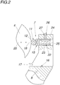
- FIGS. 1 and 2 is a bezel 1, for example, shown, which is mounted on a machine bed 2 of a machine tool 3, not shown, and a clamped workpiece 4 is supported.
- a plurality of support members 5, 6, 7 are provided on the bezel 1, which are fixed to the bezel support 8 and end in mutually angularly arranged support elements 9, 10, 11 to the workpiece 4 ends. These support elements 9, 10, 11 are designed as rollers 12.
- the support members 5, 6, 7 are also associated with actuators 13, 14, 15, via which the support members 5, 6, 7 are each mounted relative to the workpiece 4 adjustable on Lünettenitati.
- the first of these actuators 13, 14, 15 is designed as a hydraulic actuator 15 or as a hydraulic actuator. With a supply or discharge of hydraulic fluid whose operatively connected support member 7 is moved, which supports the workpiece 4 laterally on the bezel 1.
- the bezel 1 In order to be able to support a wide variety of workpieces 4 of a bezel 1, the bezel 1 according to the invention with a detachable connection or coupling 16, namely a bolted flange coupling provided.
- the clutch 16 may generally be designed as a quick coupling or any other releasable coupling is conceivable, for example, non-positive and / or positive clutches, which has not been shown in detail.
- This coupling 16 can generally in addition to its mechanical force or torque clutch and media couplings, so as to supply, for example, the hydraulic actuator 7 with liquid, and / or electrical couplings for connecting sensors, etc., which has not been shown in detail.
- this assembly 17 has a comparatively small size, despite a comparatively large cylinder diameter on the hydraulic actuator 15 in order to generate high actuating forces. Therefore, this compact assembly 17 does not increase the width of the bezel 1, whereby no disadvantages in the working space of the machine tool 3 arise.
- the effective direction 18 of the support member 7 with hydraulically actuable actuator 15 is aligned horizontally, as shown in the FIGS. 1 and 2 can be recognized.
- the hydraulically actuated actuator 15 diametrically opposite support member 5 is mechanically linearly adjustable.
- this support member 5 is associated with a spindle 19, the direction of action 20 is directed against the effective direction 18 of the support member 7.
- the horizontal support can be braced on the support member 5 and thus a possible elasticity of the support member 7 can be compensated.
- a firm or exact support of the workpiece 4 is thus created.
- a parallel to the direction of action 18 component of the direction of action 20 of the support member 5 as sufficiently conceivable to create the above effects.
- Fig. 1 can be seen in particular, the bezel 1 is attached to a carriage 21, namely on his Lünettenlie 6.
- the carriage 21 is movably mounted on a non-illustrated linear guide on the machine bed 2 of the machine tool.
- This is solved elegantly in that the assembly 17 of the steady rest 1 is located on the side of the steady rest 1 facing the machine bed 2, whereby the steady rest 1 can be adapted to a wide variety of machine beds, for example a slant bed.
- a versatile bezel 1 is created by.
- Constructive simplicity is achieved by the formation of the hydraulic actuator 15 by a hydraulic cylinder 22, the cylinder housing as the first cylinder member 23 relative to the housing 24 of the assembly 17 can be moved linearly.
- the piston rod as a second cylinder member 25 is rigidly connected to the housing 24 of the assembly 17, so that the cylinder housing is formed and retractable.
- the support member 15 is therefore formed in the manner of a quill, which is linearly adjustable centrally to the workpiece center and whose ends in the cylinder element 23 of the hydraulic cylinder 22.
- the assembly 17 has a releasable clamping device 26.
- This is for example designed as a screw clamp, which acts non-positively via its screw 26 on the cylinder housing of the hydraulic cylinder 22.
- the adjustment of the first support member 7 can be mechanically fixed to the workpiece 4, which ensures its rigid support.
- any other embodiment of the clamping device is conceivable, even hydraulically actuated clamping devices.
- These clamping devices for example, wedges, jaws, etc., which has not been shown in detail, so as to fix the adjustment of the support members 5, 6, 7.
- the after the Figures 3 and 4 illustrated bezel 100 has the difference to the after FIGS. 1 and 2 illustrated bezel 1 on the one hand, other support elements 9, 10, 11, namely shells 28, and on the other hand, another assembly 29.
- This assembly 29 differs substantially from the assembly 17 in the first support member 7.
- This support member 7 has a two-sided lever 30, the first lever arm 31 is connected to the hydraulic actuator 15, with its piston member 25 and is operated therewith. With the second lever arm 32, the support member 11 of the support member 15 is connected, via a releasable non-positive and positive connection 33.
- the trained here as a shell 28 support member 11 by a not-shown role similar to Fig. 1 - can be exchanged.
- the lintel element 11 rests on a lever extension 34 which is releasably connected to the two-sided lever 30.
- the support member 15 has no horizontal direction of action 35.
- the directions of action 36, 37 of the Stzglieder 5, 6 lead together to one of the direction of action 35 of the support member 15 oppositely directed direction of action 38, so that here the support members 5, 6 are used for bracing the support member 7 and thus increases the rigidity in the support of the workpiece becomes.
Landscapes
- Engineering & Computer Science (AREA)
- Mechanical Engineering (AREA)
- Machine Tool Units (AREA)
- Jigs For Machine Tools (AREA)
Description
- Die Erfindung betrifft eine Lünette zur Abstützung eines Werkstücks einer Werkzeugmaschine mit einem Lünettenträger nach dem Oberbegriff des Anspruchs 1 (siehe z.B.
DE2141701 ). - Bei Lünetten zur Abstützung von Werkstücken ist es bekannt (
DE2311254A ), mit hydraulischen Stellgliedern die Stützglieder der Lünette relativ zum Werkstück zu verlagern. Die als Pinolen ausgeführten Stützglieder sind zueinander winkelversetzt am Lünettenträger der Lünette befestigt, welche eine geschlossene Form aufweist. Zur Aufnahme des Werkstücks ist der Oberteil der Lünette bzw. des Lünettenträgers aufschwenkbar am Unterteil der Lünette befestigt. Die Verwendung von hydraulischen Stellgliedern kann im Allgemeinen für eine kompakte Bauform der Lünette genützt werden, weil sich damit im Vergleich mit mechanisch zu betätigbaren Stellgliedern die Anzahl an Bauteilen an der Lünette reduziert. Nachteilig weisen hydraulische Stellglieder im Vergleich zu mechanischen Stellgliedern mit gleicher Baugröße einen verminderten Stellweg auf, was die Flexibilität der Lünette zur Abstützung verschiedenster Werkstücke reduziert. Zudem sind derartige Lünetten vergleichsweise unflexibel hinsichtlich einer Anpassung der Wirkrichtung der Stützglieder auf das einzuspannende Werkstück. - Die Erfindung hat sich daher ausgehend vom Eingangs geschilderten Stand der Technik die Aufgabe gestellt, eine Lünette der eingangs geschilderten Art derart konstruktiv zu verbessern, dass trotz kleiner Baugrößen eine hohe Flexibilität in der Abstützung verschiedenster Werkstücke möglich ist. Zudem soll die Lünette konstruktiv einfach sein.
- Die Erfindung löst die gestellte Aufgabe mit einer Lünette nach Anspruch 1.
- Weist die Lünette eine Kupplung und eine Baugruppe mit dem ersten Stützglied und mit dem damit verstellbaren hydraulischen Stellglied auf, kann durch geeignete Ausstattung der Lünette äußerst flexibel auf unterschiedlichste Anforderungen hinsichtlich des Werkstücks, dessen Durchmessers und/oder der Wirkrichtungen der Stützglieder auf das Werkstück reagiert werden. Über die kuppelbare Baugruppe kann nämlich wahlweise jenes Stützglied bzw. jenes hydraulische Stellglied am Lünettenträger vorgesehen werden, mit dem der werkstückspezifische Stellweg und/oder die gewünschte Einspannung erreicht, dennoch aber eine vorgeschriebene Baugröße der Lünette nicht überschritten wird. Damit kann auch im Gegensatz zum Stand der Technik ein Optimum bei an und für sich gegenläufigen Parametern der Lünette, nämlich Stellweg, Art der Einspannung, Niederzug, etc. in Relation zur Baugröße, gefunden werden. Zudem erfordert die erfindungsgemäße kraft- und/oder formschlüssige Kupplung, beispielsweise ausgeführt als Flanschkupplung, keine besonderen konstruktiven Maßnahmen am Lünettenträger, wodurch die konstruktive Einfachheit der Lünette gewahrt bleiben kann.
- Die Genauigkeit der Abstützung des Werkstücks an der Lünette wird dadurch erhöht, dass die Wirkrichtung des ersten Stützglieds mit hydraulisch betätigbarem Stellglied einer Wirkrichtung durch ein anderes Stützglied oder mehrere andere Stützglieder mit ausschließlich mechanisch und/oder elektrisch betätigbarem Stellglied oder Stellgliedern entgegengesetzt ist. Unter Ausnützung der vergleichsweise hohen mechanischen Steifigkeit der anderen Stützglieder, die keine hydraulischen Stellglieder aufweisen, kann nämlich das dazu meist weichere hydraulische Stützglied verspannt werden. Trotz einer gewissen Kompressibilität der Hydraulikflüssigkeit kann damit dennoch eine starre Abstützung des Werkstücks an der Lünette sichergestellt werden.
- Weist die Lünette einen am Maschinenbett der Werkzeugmaschine verfahrbaren Schlitten auf, an dem der Lünettenträger befestigt ist, kann dies die Handhabung der Kupplung an der Lünette erleichtern.
- Die Lünette kann einer besonders schlanken Bauform folgen, wenn sich die Baugruppe auf der dem Maschinenbett zugewandten Seite der Lünette befindet. Die von hydraulischen Stellgliedern bekannte geringe Baugröße kann nämlich gerade in diesem Bereich des Lünettenträgers eine vergleichsweise geringe Trägerbreite ermöglichen und damit trotz der durch das nahe Maschinenbett beengten Bauverhältnissen eine vergleichsweise große Lünettenaufnahme ermöglichen.
- Das Werkstück kann in bekannter Weise besonders abgestützt werden, wenn das Stützelement je eine Rolle oder Schale aufweist.
- Kostengünstig kann das hydraulische Stellglied ausgeführt werden, in dem ein Hydraulikzylinder das hydraulische Stellglied ausbildet.
- Ist das erste Stützglied als Pinole ausgeführt, die in einem Zylinderelement des Hydraulikzylinders endet, können durch weitere konstruktive Vereinfachungen die Kosten noch weiter verringert werden.
- Die Baugröße der Lünette kann zudem weiter verringert werden, wenn das erste Stützglied einen zweiseitigen Hebel aufweist, dessen erster Hebelarm mit dem hydraulischen Stellglied verbunden ist. Zudem kann durch die Kraftumlenkung des Hebels ein vergleichsweise breites hydraulisches Stützglied verwendet werden, um eine hohe Krafterzeugung am Stürzelement zu bewirken. Beispielsweise kann hierfür ein vergleichsweise großer Zylinderdurchmesser am Hydraulikzylinder oder breite Druckdosen dienen. Außerdem kann eine Hebelausführung zur Kraftverstärkung in Wirkrichtung des Stützglieds genützt werden. Diese so ausgebildete Abstützung kann selbst vergleichsweise große Zerspanungskräfte verbessert aufnehmen, wie diese beispielsweise bei schwerem Schruppfräsen auftreten können. Zudem kann mithilfe eines Hebels konstruktiv einfach auch die Umschließung der Einspannung des Werkstücks in der Lünette auf über 180 Grad erhöht werden.
- Ist der Hebel als Winkelhebel ausgeführt, kann dies die Baugröße der Baugruppe bzw. der Lünette weiter verringern.
- Das Stützelement kann an der Baugruppe auswechselbar festgehalten werden, in dem dieses mit dem zweiten Hebelarm des Hebels über eine lösbare kraft- und/oder formschlüssige Verbindung fest verbunden ist. Damit kann unter anderem die Flexibilität der Lünette weiter erhöht werden.
- Weist die Baugruppe eine Klemmeinrichtung zur Fixierung der relativen Verstelllage deren Stützglieds zum Werkstuck auf, kann die Steifigkeit der Abstützung zusätzlich erhöht werden. Zudem kann eine eventuelle Verspannung des hydraulischen Stellglieds zum Ausgleich einer Kompressibilität der Hydraulikflüssigkeit fixiert werden.
- Ist die Kupplung gegenüber dem Stützelement eines zweiten seitlichen Stützgliedes niedriger angeordnet, das dem hydraulischen Stützglied gegenüberliegt, kann eine vergrößerte Kupplungsfläche ermöglicht und damit die Lünette standfester ausgestaltet werden.
- Vereinfache Beladungsverhältnisse beim Vorsehen des Werkstücks an der Lünette können sich ergeben, wenn am Lünettenträger zwei das Werkstück seitlich abstützende Stützglieder, die sich gegenüberliegen, und ein das Werkstück unten abstützendes Stützglied befestigt sind.
- In der Figur ist beispielsweise der Erfindungsgegenstand anhand mehrerer Ausführungsbeispiele dargestellt. Es zeigen
- Fig. 1
- eine aufgerissene Seitenansicht auf eine Lünette nach einem ersten Ausführungsbeispiel,
- Fig. 2
- eine Detailansicht der
Fig. 1 , - Fig. 3
- eine aufgerissene Seitenansicht auf weitere Lünette nach einem zweiten Ausführungsbeispiel und
- Fig. 4
- eine Detailansicht der
Fig. 3 . - Gemäß den
Figuren 1 und2 ist eine Lünette 1 beispielsweise dargestellt, die an einem Maschinenbett 2 einer nicht näher dargestellten Werkzeugmaschine 3 gelagert ist und ein eingespanntes Werkstück 4 abstützt. Hierzu sind an der Lünette 1 mehrere Stützglieder 5, 6, 7 vorgesehen, die sich am Lünettenträger 8 befestigt sind und in zueinander winkelversetzt angeordneten Stützelementen 9, 10, 11 zum Werkstück 4 hin enden. Diese Stützelemente 9, 10, 11 sind als Rollen 12 ausgeführt. Den Stützgliedern 5, 6, 7 sind zudem Stellglieder 13, 14, 15 zugeordnet, über die die Stützglieder 5, 6, 7 jeweils relativ zum Werkstück 4 verstellbar am Lünettenträger gelagert sind. Über diese Stellglieder 13, 14, 15 kann beispielsweise ein Durchhang eines in der Werkzeugmaschine 3 eingespannten Werkstücks 4 korrigiert werden. Das erste dieser Stellglieder 13, 14, 15 ist als hydraulisches Stellglied 15 bzw. als hydraulischer Aktor ausgeführt. Mit einem Zu- oder Abführen von Hydraulikflüssigkeit wird dessen wirkverbundenes Stützglied 7 bewegt, das das Werkstück 4 seitlich an der Lünette 1 abstützt. - Um unterschiedlichste Werkstücke 4 von einer Lünette 1 abstützen zu können, wird die Lünette 1 erfindungsgemäß mit einer lösbaren Verbindung bzw. Kupplung 16, nämlich einer verschraubten Flanschkupplung, versehen. Die Kupplung 16 kann im Allgemeinen auch als Schnellkupplung ausgeführt sein bzw. ist jegliche andere lösbare Kupplung vorstellbar, beispielsweise kraft- und/oder formschlüssige Kupplungen, was nicht näher dargestellt worden ist. Diese Kupplung 16 kann im Allgemeinen neben seiner mechanischen Kraft- bzw. Momentenkupplung auch Medienkupplungen, um damit beispielsweise das hydraulische Stellglied 7 mit Flüssigkeit zu versorgen, und/oder auch elektrische Kupplungen zum Anschließen von Sensoren etc. aufweisen, was nicht näher dargestellt worden ist.
- Da sowohl das Stützglied 7 mit dessen Stützelement 11 als auch das diesbezügliche hydraulische Stellglied 15 zu einer Baugruppe 17 zusammengefasst sind und diese Kupplung 16 auch zwischen dem Lünettenträger 8 und diese Baugruppe 17 vorgesehen ist, kann bei Bedarf diese seitliche Abstützung ausgetauscht werden. Bedarfsgerechte Stellwege am seitlichen Stützelement 11 sind so zu verwirklichen. Die Vorteile der Kupplung 16 gehen jedoch auch dahin gehend, dass damit auch die Art der Einspannung verändert werden kann.
- Es kann nämlich von einer Pinolenausführung des Stützglieds 7 nach
Fig. 1 auf eine Hebelausführung des Stützglieds 7 nachFig. 3 umgerüstet werden. Diese Einspannung garantiert eine vergrößerte Umschließung des Werkstücks 4 mit einem erhöhten Niederzug am Werkstück 4. Zudem zeigt diese Baugruppe 17 eine vergleichsweise geringe Baugröße, trotz eines vergleichsweise großen Zylinderdurchmessers am hydraulischen Stellglied 15, um hohe Stellkräfte erzeugen zu können. Diese kompakte Baugruppe 17 vergrößert daher auch die Breite der Lünette 1 nicht, wodurch auch keine Nachteile im Arbeitsraum der Werkzeugmaschine 3 entstehen. - Die Wirkrichtung 18 des Stützglieds 7 mit hydraulisch betätigbarem Stellglied 15 ist horizontal ausgerichtet, wie dies in den
Figuren 1 und2 erkannt werden kann. Um eine wenngleich eventuell auch geringe Kompressibilität der Hydraulikflüssigkeit des Stellglieds 15 zu kompensieren, ist das dem hydraulisch betätigbaren Stellglied 15 diametral gegenüberliegende Stützglied 5 mechanisch linear verstellbar ausgeführt. Zu diesem Zweck ist diesem Stützglied 5 eine Spindel 19 zugeordnet, dessen Wirkrichtung 20 entgegen der Wirkrichtung 18 des Stützglieds 7 gerichtet ist. Damit kann die horizontale Abstützung über das Stützglied 5 verspannt und so eine eventuelle Elastizität des Stützglieds 7 ausgeglichen werden. Eine feste bzw. exakte Abstützung des Werkstücks 4 ist damit geschaffen. In diesem Ausführungsbeispiel fallen beide Verstellrichtungen der Stützglieder 5 und 15 zusammen bzw. sind in Flucht. Im Allgemeinen ist jedoch eine zur Wirkrichtung 18 parallele Komponente der Wirkrichtung 20 des Stützglieds 5 als ausreichend denkbar, vorstehende Effekte zu schaffen. - Wie der
Fig. 1 insbesondere zu entnehmen, ist die Lünette 1 an einem Schlitten 21 befestigt, nämlich über seinen Lünettenträger 6. Der Schlitten 21 ist über eine nicht näher dargestellte Linearführung am Maschinenbett 2 der Werkzeugmaschine beweglich befestigt. Dies führt mindestens dazu, dass eine Seite des Lünettenträgers 6 dem Maschinenbett 2 nähert, wodurch beengte Bauverhältnisse in der konstruktiven Ausgestaltung der Lünette 1 zu berücksichtigen sind. Gelöst wird dies elegant dadurch, dass sich die Baugruppe 17 der Lünette 1 auf der dem Maschinenbett 2 zugewandten Seite der Lünette 1 befindet, wodurch die Lünette 1 an verschiedenste Maschinenbetten, beispielsweise auch einem Schrägbett, anpassbar ist. Eine vielseitig verwendbare Lünette 1 ist dadurch geschaffen. - Konstruktive Einfachheit wird durch die Ausbildung des hydraulischen Stellglieds 15 durch einen Hydraulikzylinder 22 erreicht, dessen Zylindergehäuse als erstes Zylinderelement 23 gegenüber dem Gehäuse 24 der Baugruppe 17 linear bewegt werden kann. Die Kolbenstange als zweites Zylinderelement 25 ist mit dem Gehäuse 24 der Baugruppe 17 starr verbunden, sodass das Zylindergehäuse aus- und einfahrbar ausgebildet ist. Das Stützglied 15 ist daher in der Art einer Pinole ausgebildet, die zentrisch zur Werkstückmitte linear verstellbar ist und dessen im Zylinderelement 23 des Hydraulikzylinders 22 endet.
- Des Weiteren weist die Baugruppe 17 eine lösbare Klemmeinrichtung 26 auf. Diese ist beispielsweise als Schraubklemme ausgebildet, die über seine Schraube 26 auf das Zylindergehäuse des Hydraulikzylinders 22 kraftschlüssig einwirkt. Damit kann die Verstelllage des ersten Stützglieds 7 zum Werkstuck 4 mechanisch fixiert werden, was dessen starre Abstützung gewährleistet.
- Im Allgemeinen ist jegliche andere Ausführungsform für die Klemmeinrichtung denkbar, selbst hydraulisch betätigbare Klemmeinrichtungen. Diese Klemmeinrichtungen können beispielsweise Keile, Klemmbacken etc. aufweisen, was nicht näher dargestellt worden ist, um damit die Verstelllage der Stützglieder 5, 6, 7 zu fixieren.
- Die nach den
Figuren 3 und4 dargestellte Lünette 100 weist zum Unterschied zur nach denFiguren 1 und2 dargestellte Lünette 1 zum einen andere Stützelemente 9, 10, 11, nämlich Schalen 28, sowie zum anderen eine andere Baugruppe 29 auf. Diese Baugruppe 29 unterscheidet sich im Wesentlichen von der Baugruppe 17 im ersten Stützglied 7. Dieses Stützglied 7 weist einen zweiseitigen Hebel 30 auf, dessen erster Hebelarm 31 mit dem hydraulischen Stellglied 15, und zwar mit dessen Kolbenelement 25 verbunden ist bzw. damit betätigt wird. Mit dem zweiten Hebelarm 32 ist das Stützelement 11 des Stützglieds 15 verbunden, und zwar über eine lösbare kraft- und formschlüssige Verbindung 33. Damit kann beispielsweise das hier als Schale 28 ausgebildete Stützelement 11 durch eine nicht näher dargestellte Rolle -ähnlich zuFig 1 - ausgetauscht werden kann. Das Stürzelement 11 lagert auf einer Hebelverlängerung 34, die mit dem zweiseitigen Hebel 30 lösbar verbunden ist. - Wie insbesondere der
Fig. 4 zu entnehmen, weist das Stützglied 15 keine horizontale Wirkrichtung 35 auf. Die Wirkrichtungen 36, 37 der Stürzglieder 5, 6 führen zusammen zu einer der Wirkrichtung 35 des Stützglieds 15 entgegengesetzt gerichtete Wirkrichtung 38, sodass auch hier die Stützglieder 5, 6 zum Verspannen des Stützglieds 7 verwendet werden und damit die Steifigkeit in der Abstützung des Werkstücks erhöht wird. - Wie nach den
Figuren 1 und3 zu erkennen, weist die Lünette 1, 100 jeweils zwei seitliche Stützglieder 5, 7 auf, die gegenüberliegen, und ein unteres Stützglied 6 auf. Die Kupplung 16 beider Lünetten 1, 100 ist zum Stützelement 9 des seitlichen Stützgliedes 5 niedriger angeordnet. Eine breite Kupplungsfläche am Lünettenträger 8 steht so zur Krafteinleitung vom Stützglied 7 in den Lünettenträger 8 zur Verfügung, was die Lünette 1, 100 trotz Kupplung 16 äußerst steif gegenüber mechanischen Belastungen macht. - Wie außerdem an den Lünetten 1, 100 nach den
Figuren 1 und3 zu erkennen, ist neben dem das Werkstück 4 seitlich abstützenden Stützgliedern 5, 7, die sich gegenüberliegen, ein das Werkstück 4 unten abstützendes Stützglied 6 am Lünettenträger 8 befestigt. Das Werkstück 4 ist so beladungsfreundlich an den Lünetten 1, 100 vorgesehen und damit abgestützt werden.
Claims (12)
- Lünette zur Abstützung eines Werkstücks (4) einer Werkzeugmaschine (3) mit einem Lünettenträger (8) zur vorzugsweisen Montage am Maschinenbett (2) der Werkzeugmaschine (3), mit mindestens einem hydraulischen Stellglied (15) und mit mehreren am Lünettenträger (8) befestigten Stützgliedern (5, 6, 7), die in zueinander winkelversetzt angeordneten Stützelementen (9, 10, 11) zur Anlage an das Werkstück (4) enden und von denen ein erstes das Werkstück (4) seitlich mit seinem Stützelement (11) abstützendes Stützglied (7) mithilfe des hydraulischen Stellglieds (15) relativ zum Werkstück (4) verstellbar am Lünettenträger (8) gelagert ist, wobei die Lünette (1, 100) eine Kupplung (16) und eine Baugruppe (17, 29) mit dem ersten Stützglied (7) und mit dem damit verstellbaren hydraulischen Stellglied (15) aufweist, wobei diese Baugruppe (17, 29) über die Kupplung (16) mit dem Lünettenträger (8) auswechselbar verbunden ist, dadurch gekennzeichnet, dass die Wirkrichtung (18, 35) des ersten Stützglieds (7) mit hydraulisch betätigbarem Stellglied (15) einer Wirkrichtung (20, 38) durch ein anderes Stützglied (5, 6) oder mehrere andere Stützglieder (5 und 6) mit ausschließlich mechanisch und/oder elektrisch betätigbaren Stellglied (13, 14) oder Stellgliedern (13 und 14) entgegengesetzt ist.
- Lünette nach Anspruch 1, dadurch gekennzeichnet, dass die Lünette (1, 100) einen am Maschinenbett (2) der Werkzeugmaschine (3) verfahrbaren Schlitten (21) aufweist, an dem der Lünettenträger (8) befestigt ist.
- Lünette nach Anspruch 2, dadurch gekennzeichnet, dass sich die Baugruppe (17, 29) auf der dem Maschinenbett (2) zugewandten Seite der Lünette (1, 100) befindet.
- Lünette nach einem der Ansprüche 1 bis 3, dadurch gekennzeichnet, dass das Stützelement (9, 10, 11) je eine Rolle (12) oder Schale (28) aufweist.
- Lünette nach einem der Ansprüche 1 bis 4, dadurch gekennzeichnet, dass ein Hydraulikzylinder (22) das hydraulische Stellglied (15) ausbildet.
- Lünette nach Anspruch 5, dadurch gekennzeichnet, dass das erste Stützglied (7) als Pinole ausgeführt ist, die in einem Zylinderelement (23) des Hydraulikzylinders (22) endet.
- Lünette nach einem der Ansprüche 1 bis 6, dadurch gekennzeichnet, dass das erste Stützglied (7) einen zweiseitigen Hebel (30) aufweist, dessen erster Hebelarm (31) mit dem hydraulischen Stellglied (15) verbunden ist.
- Lünette nach Anspruch 7, dadurch gekennzeichnet, dass der Hebel (30) als Winkelhebel ausgeführt ist.
- Lünette nach Anspruch 7 oder 8, dadurch gekennzeichnet, dass das Stützelement (11) mit dem zweiten Hebelarm (32) des Hebels (30) über eine lösbare kraft- und/oder formschlüssige Verbindung (33) fest verbunden ist.
- Lünette nach einem der Ansprüche 1 bis 9, dadurch gekennzeichnet, dass die Baugruppe (17, 29) eine Klemmeinrichtung (26) zur Fixierung der relativen Verstelllage deren Stützglieds (7) zum Werkstuck (4) aufweist.
- Lünette nach einem der Ansprüche 1 bis 10, dadurch gekennzeichnet, dass die Kupplung (16) gegenüber dem Stützelement (9) eines zweiten seitlichen Stützgliedes (5) niedriger angeordnet ist, das dem hydraulischen Stützglied (7) gegenüberliegt.
- Lünette nach einem der Ansprüche 1 bis 11, dadurch gekennzeichnet, dass am Lünettenträger (8) zwei das Werkstück (4) seitlich abstützende Stützglieder (5, 7), die sich gegenüberliegen, und ein das Werkstück (4) unten abstützendes Stützglied (6) befestigt sind.
Applications Claiming Priority (1)
| Application Number | Priority Date | Filing Date | Title |
|---|---|---|---|
| ATA50800/2013A AT515348B1 (de) | 2013-12-04 | 2013-12-04 | Lünette zur Abstützung eines Werkstücks |
Publications (2)
| Publication Number | Publication Date |
|---|---|
| EP2881218A1 EP2881218A1 (de) | 2015-06-10 |
| EP2881218B1 true EP2881218B1 (de) | 2019-04-24 |
Family
ID=52021003
Family Applications (1)
| Application Number | Title | Priority Date | Filing Date |
|---|---|---|---|
| EP14196419.7A Active EP2881218B1 (de) | 2013-12-04 | 2014-12-04 | Lünette zur Abstützung eines Werkstücks |
Country Status (2)
| Country | Link |
|---|---|
| EP (1) | EP2881218B1 (de) |
| AT (1) | AT515348B1 (de) |
Families Citing this family (2)
| Publication number | Priority date | Publication date | Assignee | Title |
|---|---|---|---|---|
| CN115922371B (zh) * | 2023-01-09 | 2025-08-15 | 山西平阳重工机械有限责任公司 | 一种数控车床跟刀架液压自动调距柔性装置 |
| CN116810288A (zh) * | 2023-07-26 | 2023-09-29 | 成都航空职业技术学院 | 一种可自动旋转的圆管焊接工装夹具 |
Family Cites Families (6)
| Publication number | Priority date | Publication date | Assignee | Title |
|---|---|---|---|---|
| DE2141701A1 (de) * | 1971-08-20 | 1973-03-01 | Bruno Dietl | Stuetzvorrichtung zur halterung von schweren werkstuecken auf werkzeugmaschinen |
| DE2311254A1 (de) | 1973-03-07 | 1974-09-12 | Theodor Heisterkamp | Drehbankluenette mit hydraulisch einstellbaren pinolen |
| DE2547615A1 (de) * | 1975-10-24 | 1977-04-28 | Eugen Maier | Einrichtung zum aufspannen und/oder zur halterung eines werkstueckes auf arbeitsmaschinen |
| DE8701674U1 (de) * | 1987-02-04 | 1987-04-02 | GWT Gesellschaft für Gewindewirbel- & Tiefbohrtechnik mbH, 3564 Steffenberg | Führungs- oder Einspannvorrichtung für Werkstücke |
| DE3719103A1 (de) * | 1987-06-06 | 1988-12-22 | Smw Spanneinrichtungen | Luenette |
| DE20119931U1 (de) * | 2001-12-08 | 2002-03-28 | H. Richter Vorrichtungsbau GmbH, 30855 Langenhagen | Schnellzentrierbare Lünette |
-
2013
- 2013-12-04 AT ATA50800/2013A patent/AT515348B1/de active
-
2014
- 2014-12-04 EP EP14196419.7A patent/EP2881218B1/de active Active
Non-Patent Citations (1)
| Title |
|---|
| None * |
Also Published As
| Publication number | Publication date |
|---|---|
| AT515348B1 (de) | 2015-10-15 |
| EP2881218A1 (de) | 2015-06-10 |
| AT515348A1 (de) | 2015-08-15 |
Similar Documents
| Publication | Publication Date | Title |
|---|---|---|
| AT504640B1 (de) | Biegemaschine | |
| EP3875215B1 (de) | Nullpunktspannplatte, werkzeugmaschine mit selbiger und spannvorrichtung | |
| DE202017100994U1 (de) | Querträgerschrauben-Stützeinrichtung für Bearbeitungsmaschinen in Portalform | |
| EP2783791B1 (de) | Positioniereinrichtung in Portalbauweise | |
| EP3403738B1 (de) | Blechbiegemaschine | |
| EP3077133B1 (de) | Biegepresse | |
| EP2694230B1 (de) | Radialpresse | |
| EP2701860B1 (de) | Werkzeughalterung für abkantpresse | |
| DE102010028032B4 (de) | Werkzeugmaschine mit zusätzlichem Zuganker | |
| EP3370892B1 (de) | Greifersystem für eine biegepresse | |
| EP3093102A1 (de) | Lünette | |
| AT515153A1 (de) | Biegemaschine | |
| DE202016007588U1 (de) | Einschraubhilfe zum Halten und Ausrichten einer Schraube | |
| DE2411744C3 (de) | Presse zum Pressverbinden eines Kabels oder isolierten Drahtes mit einem Kabelschuh | |
| EP2846966B1 (de) | Transferzentrum zur spanenden bearbeitung mindestens eines werkstücks, mit einem positionsausgleichssystem | |
| EP2025444B1 (de) | Niederzugspannvorrichtung zum Spannen in Bohrungen und Innenkonturen von Gegenständen | |
| AT515348B1 (de) | Lünette zur Abstützung eines Werkstücks | |
| EP4279659B1 (de) | Schlitzwandgerät und verfahren zum erstellen eines schlitzes im boden | |
| EP3113892B1 (de) | Werkzeugschieber | |
| EP2103367A1 (de) | Spanneinrichtung für Gegenstände z.B. für zu bearbeitende Werkstücke | |
| DE10311392A1 (de) | Biegemaschine, insbesondere für Schweiß- und Spanntische, sowie Schweiß- und Spanntisch | |
| EP1941956A1 (de) | Anbiegepresse zum Biegen eines Blechs bei der Herstellung eines Rohres | |
| EP2371482A1 (de) | Werkzeugmaschine | |
| DE102012212213B4 (de) | Horizontalschlitten für eine Werkzeugmaschine | |
| EP2747929B1 (de) | Werkzeug zum bearbeiten von werkstücken |
Legal Events
| Date | Code | Title | Description |
|---|---|---|---|
| PUAI | Public reference made under article 153(3) epc to a published international application that has entered the european phase |
Free format text: ORIGINAL CODE: 0009012 |
|
| 17P | Request for examination filed |
Effective date: 20141204 |
|
| AK | Designated contracting states |
Kind code of ref document: A1 Designated state(s): AL AT BE BG CH CY CZ DE DK EE ES FI FR GB GR HR HU IE IS IT LI LT LU LV MC MK MT NL NO PL PT RO RS SE SI SK SM TR |
|
| AX | Request for extension of the european patent |
Extension state: BA ME |
|
| R17P | Request for examination filed (corrected) |
Effective date: 20151210 |
|
| RBV | Designated contracting states (corrected) |
Designated state(s): AL AT BE BG CH CY CZ DE DK EE ES FI FR GB GR HR HU IE IS IT LI LT LU LV MC MK MT NL NO PL PT RO RS SE SI SK SM TR |
|
| STAA | Information on the status of an ep patent application or granted ep patent |
Free format text: STATUS: EXAMINATION IS IN PROGRESS |
|
| 17Q | First examination report despatched |
Effective date: 20161124 |
|
| GRAP | Despatch of communication of intention to grant a patent |
Free format text: ORIGINAL CODE: EPIDOSNIGR1 |
|
| STAA | Information on the status of an ep patent application or granted ep patent |
Free format text: STATUS: GRANT OF PATENT IS INTENDED |
|
| INTG | Intention to grant announced |
Effective date: 20181105 |
|
| GRAS | Grant fee paid |
Free format text: ORIGINAL CODE: EPIDOSNIGR3 |
|
| GRAA | (expected) grant |
Free format text: ORIGINAL CODE: 0009210 |
|
| STAA | Information on the status of an ep patent application or granted ep patent |
Free format text: STATUS: THE PATENT HAS BEEN GRANTED |
|
| AK | Designated contracting states |
Kind code of ref document: B1 Designated state(s): AL AT BE BG CH CY CZ DE DK EE ES FI FR GB GR HR HU IE IS IT LI LT LU LV MC MK MT NL NO PL PT RO RS SE SI SK SM TR |
|
| REG | Reference to a national code |
Ref country code: GB Ref legal event code: FG4D Free format text: NOT ENGLISH |
|
| REG | Reference to a national code |
Ref country code: CH Ref legal event code: EP |
|
| REG | Reference to a national code |
Ref country code: AT Ref legal event code: REF Ref document number: 1123563 Country of ref document: AT Kind code of ref document: T Effective date: 20190515 Ref country code: IE Ref legal event code: FG4D Free format text: LANGUAGE OF EP DOCUMENT: GERMAN |
|
| REG | Reference to a national code |
Ref country code: DE Ref legal event code: R096 Ref document number: 502014011504 Country of ref document: DE |
|
| REG | Reference to a national code |
Ref country code: NL Ref legal event code: MP Effective date: 20190424 |
|
| REG | Reference to a national code |
Ref country code: LT Ref legal event code: MG4D |
|
| PG25 | Lapsed in a contracting state [announced via postgrant information from national office to epo] |
Ref country code: NL Free format text: LAPSE BECAUSE OF FAILURE TO SUBMIT A TRANSLATION OF THE DESCRIPTION OR TO PAY THE FEE WITHIN THE PRESCRIBED TIME-LIMIT Effective date: 20190424 |
|
| PG25 | Lapsed in a contracting state [announced via postgrant information from national office to epo] |
Ref country code: ES Free format text: LAPSE BECAUSE OF FAILURE TO SUBMIT A TRANSLATION OF THE DESCRIPTION OR TO PAY THE FEE WITHIN THE PRESCRIBED TIME-LIMIT Effective date: 20190424 Ref country code: LT Free format text: LAPSE BECAUSE OF FAILURE TO SUBMIT A TRANSLATION OF THE DESCRIPTION OR TO PAY THE FEE WITHIN THE PRESCRIBED TIME-LIMIT Effective date: 20190424 Ref country code: HR Free format text: LAPSE BECAUSE OF FAILURE TO SUBMIT A TRANSLATION OF THE DESCRIPTION OR TO PAY THE FEE WITHIN THE PRESCRIBED TIME-LIMIT Effective date: 20190424 Ref country code: FI Free format text: LAPSE BECAUSE OF FAILURE TO SUBMIT A TRANSLATION OF THE DESCRIPTION OR TO PAY THE FEE WITHIN THE PRESCRIBED TIME-LIMIT Effective date: 20190424 Ref country code: NO Free format text: LAPSE BECAUSE OF FAILURE TO SUBMIT A TRANSLATION OF THE DESCRIPTION OR TO PAY THE FEE WITHIN THE PRESCRIBED TIME-LIMIT Effective date: 20190724 Ref country code: PT Free format text: LAPSE BECAUSE OF FAILURE TO SUBMIT A TRANSLATION OF THE DESCRIPTION OR TO PAY THE FEE WITHIN THE PRESCRIBED TIME-LIMIT Effective date: 20190824 Ref country code: SE Free format text: LAPSE BECAUSE OF FAILURE TO SUBMIT A TRANSLATION OF THE DESCRIPTION OR TO PAY THE FEE WITHIN THE PRESCRIBED TIME-LIMIT Effective date: 20190424 Ref country code: AL Free format text: LAPSE BECAUSE OF FAILURE TO SUBMIT A TRANSLATION OF THE DESCRIPTION OR TO PAY THE FEE WITHIN THE PRESCRIBED TIME-LIMIT Effective date: 20190424 |
|
| PG25 | Lapsed in a contracting state [announced via postgrant information from national office to epo] |
Ref country code: LV Free format text: LAPSE BECAUSE OF FAILURE TO SUBMIT A TRANSLATION OF THE DESCRIPTION OR TO PAY THE FEE WITHIN THE PRESCRIBED TIME-LIMIT Effective date: 20190424 Ref country code: GR Free format text: LAPSE BECAUSE OF FAILURE TO SUBMIT A TRANSLATION OF THE DESCRIPTION OR TO PAY THE FEE WITHIN THE PRESCRIBED TIME-LIMIT Effective date: 20190725 Ref country code: PL Free format text: LAPSE BECAUSE OF FAILURE TO SUBMIT A TRANSLATION OF THE DESCRIPTION OR TO PAY THE FEE WITHIN THE PRESCRIBED TIME-LIMIT Effective date: 20190424 Ref country code: BG Free format text: LAPSE BECAUSE OF FAILURE TO SUBMIT A TRANSLATION OF THE DESCRIPTION OR TO PAY THE FEE WITHIN THE PRESCRIBED TIME-LIMIT Effective date: 20190724 Ref country code: RS Free format text: LAPSE BECAUSE OF FAILURE TO SUBMIT A TRANSLATION OF THE DESCRIPTION OR TO PAY THE FEE WITHIN THE PRESCRIBED TIME-LIMIT Effective date: 20190424 |
|
| PG25 | Lapsed in a contracting state [announced via postgrant information from national office to epo] |
Ref country code: IS Free format text: LAPSE BECAUSE OF FAILURE TO SUBMIT A TRANSLATION OF THE DESCRIPTION OR TO PAY THE FEE WITHIN THE PRESCRIBED TIME-LIMIT Effective date: 20190824 |
|
| REG | Reference to a national code |
Ref country code: DE Ref legal event code: R097 Ref document number: 502014011504 Country of ref document: DE |
|
| PG25 | Lapsed in a contracting state [announced via postgrant information from national office to epo] |
Ref country code: RO Free format text: LAPSE BECAUSE OF FAILURE TO SUBMIT A TRANSLATION OF THE DESCRIPTION OR TO PAY THE FEE WITHIN THE PRESCRIBED TIME-LIMIT Effective date: 20190424 Ref country code: CZ Free format text: LAPSE BECAUSE OF FAILURE TO SUBMIT A TRANSLATION OF THE DESCRIPTION OR TO PAY THE FEE WITHIN THE PRESCRIBED TIME-LIMIT Effective date: 20190424 Ref country code: EE Free format text: LAPSE BECAUSE OF FAILURE TO SUBMIT A TRANSLATION OF THE DESCRIPTION OR TO PAY THE FEE WITHIN THE PRESCRIBED TIME-LIMIT Effective date: 20190424 Ref country code: SK Free format text: LAPSE BECAUSE OF FAILURE TO SUBMIT A TRANSLATION OF THE DESCRIPTION OR TO PAY THE FEE WITHIN THE PRESCRIBED TIME-LIMIT Effective date: 20190424 Ref country code: DK Free format text: LAPSE BECAUSE OF FAILURE TO SUBMIT A TRANSLATION OF THE DESCRIPTION OR TO PAY THE FEE WITHIN THE PRESCRIBED TIME-LIMIT Effective date: 20190424 |
|
| PG25 | Lapsed in a contracting state [announced via postgrant information from national office to epo] |
Ref country code: SM Free format text: LAPSE BECAUSE OF FAILURE TO SUBMIT A TRANSLATION OF THE DESCRIPTION OR TO PAY THE FEE WITHIN THE PRESCRIBED TIME-LIMIT Effective date: 20190424 |
|
| PLBE | No opposition filed within time limit |
Free format text: ORIGINAL CODE: 0009261 |
|
| STAA | Information on the status of an ep patent application or granted ep patent |
Free format text: STATUS: NO OPPOSITION FILED WITHIN TIME LIMIT |
|
| PG25 | Lapsed in a contracting state [announced via postgrant information from national office to epo] |
Ref country code: TR Free format text: LAPSE BECAUSE OF FAILURE TO SUBMIT A TRANSLATION OF THE DESCRIPTION OR TO PAY THE FEE WITHIN THE PRESCRIBED TIME-LIMIT Effective date: 20190424 |
|
| 26N | No opposition filed |
Effective date: 20200127 |
|
| PG25 | Lapsed in a contracting state [announced via postgrant information from national office to epo] |
Ref country code: SI Free format text: LAPSE BECAUSE OF FAILURE TO SUBMIT A TRANSLATION OF THE DESCRIPTION OR TO PAY THE FEE WITHIN THE PRESCRIBED TIME-LIMIT Effective date: 20190424 |
|
| REG | Reference to a national code |
Ref country code: CH Ref legal event code: PL |
|
| REG | Reference to a national code |
Ref country code: BE Ref legal event code: MM Effective date: 20191231 |
|
| PG25 | Lapsed in a contracting state [announced via postgrant information from national office to epo] |
Ref country code: MC Free format text: LAPSE BECAUSE OF FAILURE TO SUBMIT A TRANSLATION OF THE DESCRIPTION OR TO PAY THE FEE WITHIN THE PRESCRIBED TIME-LIMIT Effective date: 20190424 |
|
| PG25 | Lapsed in a contracting state [announced via postgrant information from national office to epo] |
Ref country code: IE Free format text: LAPSE BECAUSE OF NON-PAYMENT OF DUE FEES Effective date: 20191204 Ref country code: LU Free format text: LAPSE BECAUSE OF NON-PAYMENT OF DUE FEES Effective date: 20191204 |
|
| PG25 | Lapsed in a contracting state [announced via postgrant information from national office to epo] |
Ref country code: LI Free format text: LAPSE BECAUSE OF NON-PAYMENT OF DUE FEES Effective date: 20191231 Ref country code: CH Free format text: LAPSE BECAUSE OF NON-PAYMENT OF DUE FEES Effective date: 20191231 Ref country code: BE Free format text: LAPSE BECAUSE OF NON-PAYMENT OF DUE FEES Effective date: 20191231 |
|
| PG25 | Lapsed in a contracting state [announced via postgrant information from national office to epo] |
Ref country code: CY Free format text: LAPSE BECAUSE OF FAILURE TO SUBMIT A TRANSLATION OF THE DESCRIPTION OR TO PAY THE FEE WITHIN THE PRESCRIBED TIME-LIMIT Effective date: 20190424 |
|
| PG25 | Lapsed in a contracting state [announced via postgrant information from national office to epo] |
Ref country code: MT Free format text: LAPSE BECAUSE OF FAILURE TO SUBMIT A TRANSLATION OF THE DESCRIPTION OR TO PAY THE FEE WITHIN THE PRESCRIBED TIME-LIMIT Effective date: 20190424 Ref country code: HU Free format text: LAPSE BECAUSE OF FAILURE TO SUBMIT A TRANSLATION OF THE DESCRIPTION OR TO PAY THE FEE WITHIN THE PRESCRIBED TIME-LIMIT; INVALID AB INITIO Effective date: 20141204 |
|
| PG25 | Lapsed in a contracting state [announced via postgrant information from national office to epo] |
Ref country code: MK Free format text: LAPSE BECAUSE OF FAILURE TO SUBMIT A TRANSLATION OF THE DESCRIPTION OR TO PAY THE FEE WITHIN THE PRESCRIBED TIME-LIMIT Effective date: 20190424 |
|
| P01 | Opt-out of the competence of the unified patent court (upc) registered |
Effective date: 20230514 |
|
| PGFP | Annual fee paid to national office [announced via postgrant information from national office to epo] |
Ref country code: GB Payment date: 20251218 Year of fee payment: 12 |
|
| PGFP | Annual fee paid to national office [announced via postgrant information from national office to epo] |
Ref country code: AT Payment date: 20251215 Year of fee payment: 12 |
|
| PGFP | Annual fee paid to national office [announced via postgrant information from national office to epo] |
Ref country code: FR Payment date: 20251217 Year of fee payment: 12 |
|
| PGFP | Annual fee paid to national office [announced via postgrant information from national office to epo] |
Ref country code: DE Payment date: 20251222 Year of fee payment: 12 |
|
| PGFP | Annual fee paid to national office [announced via postgrant information from national office to epo] |
Ref country code: IT Payment date: 20251231 Year of fee payment: 12 |