EP2881004A1 - Skistiefel - Google Patents
Skistiefel Download PDFInfo
- Publication number
- EP2881004A1 EP2881004A1 EP14196672.1A EP14196672A EP2881004A1 EP 2881004 A1 EP2881004 A1 EP 2881004A1 EP 14196672 A EP14196672 A EP 14196672A EP 2881004 A1 EP2881004 A1 EP 2881004A1
- Authority
- EP
- European Patent Office
- Prior art keywords
- shell
- shaped
- ski boot
- boot
- cuff
- Prior art date
- Legal status (The legal status is an assumption and is not a legal conclusion. Google has not performed a legal analysis and makes no representation as to the accuracy of the status listed.)
- Granted
Links
- 210000002683 foot Anatomy 0.000 claims abstract description 17
- 230000027455 binding Effects 0.000 claims abstract description 15
- 238000009739 binding Methods 0.000 claims abstract description 15
- 210000003423 ankle Anatomy 0.000 claims abstract description 8
- 239000002131 composite material Substances 0.000 claims description 18
- 239000004033 plastic Substances 0.000 claims description 15
- 239000013536 elastomeric material Substances 0.000 claims description 4
- 239000007769 metal material Substances 0.000 claims description 4
- 229920001971 elastomer Polymers 0.000 claims description 3
- 230000008878 coupling Effects 0.000 claims description 2
- 238000010168 coupling process Methods 0.000 claims description 2
- 238000005859 coupling reaction Methods 0.000 claims description 2
- 230000007423 decrease Effects 0.000 claims description 2
- 230000001681 protective effect Effects 0.000 description 17
- 239000000463 material Substances 0.000 description 7
- 239000004677 Nylon Substances 0.000 description 4
- 239000004952 Polyamide Substances 0.000 description 4
- 229920002614 Polyether block amide Polymers 0.000 description 4
- 229920001778 nylon Polymers 0.000 description 4
- 229920002647 polyamide Polymers 0.000 description 4
- 229920006149 polyester-amide block copolymer Polymers 0.000 description 4
- 229920000642 polymer Polymers 0.000 description 4
- 238000004026 adhesive bonding Methods 0.000 description 3
- 238000009304 pastoral farming Methods 0.000 description 3
- OKTJSMMVPCPJKN-UHFFFAOYSA-N Carbon Chemical compound [C] OKTJSMMVPCPJKN-UHFFFAOYSA-N 0.000 description 2
- 239000004760 aramid Substances 0.000 description 2
- 229920003235 aromatic polyamide Polymers 0.000 description 2
- 229910052799 carbon Inorganic materials 0.000 description 2
- 239000005007 epoxy-phenolic resin Substances 0.000 description 2
- 239000000835 fiber Substances 0.000 description 2
- 239000011152 fibreglass Substances 0.000 description 2
- 230000003100 immobilizing effect Effects 0.000 description 2
- 239000011810 insulating material Substances 0.000 description 2
- 229920001225 polyester resin Polymers 0.000 description 2
- 239000004645 polyester resin Substances 0.000 description 2
- 239000011435 rock Substances 0.000 description 2
- 230000035807 sensation Effects 0.000 description 2
- 229920001187 thermosetting polymer Polymers 0.000 description 2
- 230000015572 biosynthetic process Effects 0.000 description 1
- 230000001419 dependent effect Effects 0.000 description 1
- 238000005516 engineering process Methods 0.000 description 1
- 238000001746 injection moulding Methods 0.000 description 1
- 238000003780 insertion Methods 0.000 description 1
- 230000037431 insertion Effects 0.000 description 1
- 230000003993 interaction Effects 0.000 description 1
- 239000004579 marble Substances 0.000 description 1
- 238000012986 modification Methods 0.000 description 1
- 230000004048 modification Effects 0.000 description 1
- 230000000284 resting effect Effects 0.000 description 1
Images


Classifications
-
- A—HUMAN NECESSITIES
- A43—FOOTWEAR
- A43B—CHARACTERISTIC FEATURES OF FOOTWEAR; PARTS OF FOOTWEAR
- A43B5/00—Footwear for sporting purposes
- A43B5/04—Ski or like boots
- A43B5/0415—Accessories
- A43B5/0417—Accessories for soles or associated with soles of ski boots; for ski bindings
- A43B5/0419—Accessories for soles or associated with soles of ski boots; for ski bindings for walking aids
-
- A—HUMAN NECESSITIES
- A43—FOOTWEAR
- A43B—CHARACTERISTIC FEATURES OF FOOTWEAR; PARTS OF FOOTWEAR
- A43B13/00—Soles; Sole-and-heel integral units
- A43B13/14—Soles; Sole-and-heel integral units characterised by the constructive form
- A43B13/143—Soles; Sole-and-heel integral units characterised by the constructive form provided with wedged, concave or convex end portions, e.g. for improving roll-off of the foot
- A43B13/145—Convex portions, e.g. with a bump or projection, e.g. 'Masai' type shoes
-
- A—HUMAN NECESSITIES
- A43—FOOTWEAR
- A43B—CHARACTERISTIC FEATURES OF FOOTWEAR; PARTS OF FOOTWEAR
- A43B5/00—Footwear for sporting purposes
- A43B5/04—Ski or like boots
- A43B5/0427—Ski or like boots characterised by type or construction details
- A43B5/047—Ski or like boots characterised by type or construction details provided with means to improve walking with the skiboot
-
- A—HUMAN NECESSITIES
- A43—FOOTWEAR
- A43B—CHARACTERISTIC FEATURES OF FOOTWEAR; PARTS OF FOOTWEAR
- A43B5/00—Footwear for sporting purposes
- A43B5/04—Ski or like boots
- A43B5/0496—Ski or like boots boots for touring or hiking skis
Definitions
- the present invention relates to a ski boot.
- the present invention relates to a mountaineering ski boot, use to which the following disclosure will explicitly refer without however losing in generality.
- more recent mountaineering ski boots basically consist of a rigid shell made of plastic material and which is shaped so as to accommodate the foot of the skier, and is provided on the bottom with a front sole and a rear heel made of non-slip elastomeric material; and of a rigid tubular cuff made of plastic material and which is substantially C-shaped so as to embrace the lower section of the skier's leg from behind, and is hinged to the upper part of the shell so as to rotate about a transversal reference axis which is substantially perpendicular to the midplane of the boot, and is also locally substantially coincident with the articulation axis of the ankle.
- the above-mentioned mountaineering ski boots are also provided with an inner liner made of soft and thermal insulating material, which is inserted into the shell and the cuff, and is shaped so as to accommodate and protect both the foot and the lower section of the skier's leg; and with a series of manually-operated closing members that are located both on the shell and on the cuff, and are structured so as to selectively close/tighten the shell and the cuff to immobilize the skier's leg stably inside the liner.
- mountaineering ski boots are generally also provided with a manually-operated cuff locking device which is usually located in the area immediately above the heel of the boot, straddling the shell and the cuff, and is structured so as to be able to selectively and alternatively, rigidly lock the cuff to the shell in a given tilted position; or to unlock/release the cuff completely from the shell so as to allow the cuff to freely swing on the shell.
- a manually-operated cuff locking device which is usually located in the area immediately above the heel of the boot, straddling the shell and the cuff, and is structured so as to be able to selectively and alternatively, rigidly lock the cuff to the shell in a given tilted position; or to unlock/release the cuff completely from the shell so as to allow the cuff to freely swing on the shell.
- the lower part of the rigid shell is instead specifically structured so as to couple in a rigid and stable, though easily releasable, manner with the toe-piece and with the heel-piece of a mountaineering ski binding device, which is in turn structured to be rigidly fixed on the back of a downhill ski or the like.
- the toe-piece and the heel-piece of the mountaineering ski binding device are structured so as to allow the skier to raise the heel of the ski boot, when necessary, while always and in any case keeping the tip of the boot, or better the tip of the shell, firmly anchored to the ski.
- Aim of the present invention is to improve the kinematic interaction between the mountaineering ski boot and the mountaineering ski binding device, so as to increase the skier's performance without however significantly increasing the cost of the bindings and/or of the mountaineering ski boots.
- a ski boot as defined in claim 1, and preferably, though not necessarily, in any one of the claims dependent thereon.
- numeral 1 indicates as a whole a ski boot, and in particular a ski boot specifically structured for practicing the sport of ski mountaineering.
- the ski boot 1 basically consists of a rigid shell 2 made of plastic and/or composite material, which is shaped so as to accommodate the foot of the user, and has the lower part specifically structured/shaped so as to couple/bind in a rigid and stable, though easily releasable manner with a ski binding device of known type, which in turn is structured to be rigidly fastened to the back of a downhill ski or the like; and of a rigid cuff 3 made of plastic and/or composite material, which is shaped so as to enclose the ankle of the user, and is hinged on the upper part of shell 2 so as to freely swing about a transversal reference axis R which is locally substantially perpendicular to the vertical midplane of the boot (i.e. perpendicular to the plane of the sheet in figure 2 ), and is moreover locally substantially coincident with the articulation axis of the ankle of the user.
- a transversal reference axis R which is locally substantially perpendicular to the vertical midplane of the boot (i
- the lower part of shell 2 is preferably specifically structured/shaped so as to couple/bind in a rigid and stable, though easily releasable, manner with the toe-piece and with the heel-piece of a known mountaineering ski binding device, which is in turn structured to be rigidly fixed on the back of a downhill ski or the like.
- Cuff 3 instead is preferably fixed in freely rotatable manner to shell 2 by means of two lateral connection hinges 4 which are located on the inner and outer lateral sides of shell 2 and of cuff 3, aligned along axis R, so as to allow cuff 3 to freely swing both forwards and backwards on shell 2, while always remaining on a reference plane which is orthogonal to axis R and is substantially coincident with the midplane of the boot.
- the ski boot 1 preferably also comprises an inner liner 5 which is preferably made of soft and/or thermal insulating material, is accommodated inside shell 2 and cuff 3 preferably, though not necessarily, in removable manner, and is shaped so as to accommodate, envelope and protect the foot and the lower section of the leg of the user; and a manually-operated, mechanical boot closing system which is structured so as to be able to selectively close/tighten shell 2 and cuff 3 for immobilizing the leg of the user stably inside the ski boot 1, or better, the inner liner 5.
- an inner liner 5 which is preferably made of soft and/or thermal insulating material, is accommodated inside shell 2 and cuff 3 preferably, though not necessarily, in removable manner, and is shaped so as to accommodate, envelope and protect the foot and the lower section of the leg of the user; and a manually-operated, mechanical boot closing system which is structured so as to be able to selectively close/tighten shell 2 and cuff 3 for immobilizing the leg of the user stab
- the boot closing system preferably, though not necessarily, consists of two independent manually-operated closing members 7 and 8, which are located one on shell 2 and the other on cuff 3, and are structured so as to be able to selectively close /tighten 3, respectively, shell 2 and cuff for immobilizing the leg of the user stably inside the ski boot 1, or better, the inner liner 5.
- the ski boot 1 is finally also provided with an automatic or manually-operated cuff locking device 9, which is preferably located in the area immediately above the heel of the boot, straddling shell 2 and cuff 3, and is structured so as to be able to, selectively and alternatively,
- shell 2 instead basically consists of a substantially basin-shaped rigid casing 10 made of plastic or composite material, which is shaped so as to accommodate the foot of the user; and of a front sole 11 and a rear heel 12, which are preferably made of rubber or other elastomeric material, and are located on the lower wall 13 of rigid casing 10, respectively at the tarsal-phalangeal area and at the heel area of the sole of the foot.
- sole 11 and heel 12 are preferably attached in unmovable manner on the lower wall 13 of rigid casing 10, preferably by means of gluing.
- the lower part of casing 10 is moreover specifically structured/shaped so as to couple/bind in a rigid and stable, though easily releasable, manner with the toe-piece and with the heel-piece, respectively, of the ski binding device or mountaineering ski binding device.
- the rigid casing 10 is preferably provided, at front, with a substantially duckbill-shaped protruding tailpiece 14, which protrudes cantilevered beyond the front edge of sole 11 thus substantially forming an extension of the lower wall 13 of the casing, and which is structured so as to couple in a known manner with the toe-piece of a mountaineering ski binding device.
- a transversal stiffening bar or insert 15 made of metal material, which is arranged substantially perpendicular to the midplane of the boot, and surfaces with the two ends outside casing 10 at the two lateral sides of protruding tailpiece 14.
- shell 2 also comprises a coupling plate 16 made of metal material, which is rigidly attached to the rear part of rigid casing 10, immediately above the rear heel 12 and substantially straddling the midplane of the boot, and is structured so as to be able to couple in a known manner with the heel-piece of a mountaineering ski binding device.
- a coupling plate 16 made of metal material, which is rigidly attached to the rear part of rigid casing 10, immediately above the rear heel 12 and substantially straddling the midplane of the boot, and is structured so as to be able to couple in a known manner with the heel-piece of a mountaineering ski binding device.
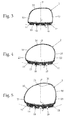
- the lower part of shell 2 incorporating the front sole 11 is shaped substantially like the bowl of a spoon, so as to define a front ground-resting surface 18 with an arched profile at least orthogonally to the midplane of boot P.
- the portion of lower wall 13 of rigid casing 10 that supports the front sole 11, i.e. the front portion of lower wall 13, and/or the front sole 11 are shaped substantially like the bowl of a spoon so as to define a front ground-resting surface 18 with an arched profile at least orthogonally to the midplane of boot P.
- the front portion of lower wall 13 of rigid casing 10 and/or the front sole 11 are shaped substantially like the bowl of a spoon so as to define a front ground-resting surface 18 with an arched profile both parallel and orthogonally to the midplane of boot P.
- the radius of curvature r of the front ground-resting surface 18 also ranges preferably, though not necessarily, between 100 and 3000 cm (centimetres).
- the value of the radius of curvature r of the front ground-resting surface 18 increases progressively as the distance from the tip of the boot increases, i.e. from the protruding tailpiece of the rigid shell 10.
- the portion of lower wall 13 of rigid casing 10 that supports the front sole 3, i.e. the front portion of lower wall 13, is preferably cambered substantially like the bowl of a spoon; whereas the front sole 11 has a nominal thickness s preferably substantially constant and a profile which matches the shape of the front portion of lower wall 13.
- the front portion of lower wall 13 moreover has a preferably substantially constant thickness, and is preferably provided, at the midplane of boot P and orthogonally to the same midplane, with a radius of curvature r, which preferably, though not necessarily, ranges between 100 and 3000 cm (centimetres).
- the front sole 11 may have a variable thickness which decreases as the distance from the midplane of boot P increases, so as to increase the bowl-shape of the front ground-resting surface 18 with respect to the one of the front portion of lower wall 13 of casing 10.
- the lower part of shell 2 incorporating the heel 12 is instead substantially flat, so as to define a rear ground-resting surface 19 which is substantially flat and is locally substantially perpendicular to the midplane P of the boot.
- the portion of lower wall 13 of rigid casing 10 that supports the rear heel 12, and/or the rear heel 12 are substantially flat, so as to define a rear ground-resting surface 19 which is substantially flat and is locally substantially perpendicular to the midplane P of the boot.
- shell 2 in addition comprises an oblong-shaped flattened protective tongue 20, which is located to rest on the upper part of casing 10, to cover a longitudinal slit 21 extending along the upper wall of casing 10, more or less above the upper part of the instep of the user's foot, and is structured/ sized so as to allow the casing 10 to expand temporarily to facilitate the insertion and removal of the foot of the user from the liner 5.
- the protective tongue 20 is preferably arranged straddling the vertical midplane P of the boot, and extends grazing the upper part of casing 10, i.e. grazing the area of casing 10 immediately above the instep of the foot and possibly also the tibia-astragalus junction of the ankle, to cover the longitudinal slit 21.
- casing 10 is preferably made of composite material, whereas the protective tongue 20 is preferably, though not necessarily, made of plastic material.
- casing 10 is preferably, though not necessarily, made of a composite material formed by one or more overlapping layers of carbon fibre and/or fibre glass and/or aramid fibre, which are conveniently braided and/or overlap each other and are embedded in an epoxy phenolic or polyester resin, preferably of the thermosetting type.
- Front sole 11 and rear heel 12 instead are preferably made of rubber or other non-slip elastomeric material and are preferably, though not necessarily provided with a treaded profile.
- Protective tongue 20 is instead preferably, though not necessarily, made of nylon (polyamide), PEBAX (polyester-amide) or similar plastic polymers.
- shell 2 additionally comprises a front protective cap 22 made of plastic material, which covers the outer surface of the tip of the composite material casing 10, and is fixed in unmovable manner to said casing 10 preferably by means of gluing.
- the protective cap 22 may also be made by injection moulding, directly on the tip of the composite -material casing 10.
- the protective cap 22 is preferably substantially cup-shaped, and preferably extends to cover the area of the tip of the composite material casing 10 which is above the protruding tailpiece 14.
- the protective cap 22 is also made of nylon (polyamide), PEBAX (polyester-amide) or similar plastic polymers.
- the protective cap 22 is preferably also provided with a protruding tab which extends grazing the outer surface of the composite material casing 10 up to reach the upper part of shell 2 above the phalanx area of the foot, and then extends towards the longitudinal slit 21 up to reach the lower end of protective tongue 20 where joins the latter without interruption.
- the protective tongue 20 is preferably made in one piece with protective cap 22.
- shell 2 is finally provided, on the inner and outer lateral sides of the composite material casing 10, with two protective lateral bands 23 made of plastic material preferably, though not necessarily, of elastomeric type, which extend upwards starting from the lateral edges of sole 11, while continuing to graze the outer surface of the composite material casing 10, and are attached in unmovable manner to the composite material casing 10 preferably by means of gluing.
- the two lateral bands 23 are moreover shaped so as to enclose/embrace the composite material casing 10 on opposite sides thereof, at the tarsal-phalangeal area of the foot and preferably up to the area of the arch of the sole, i.e. at front sole 11.
- the two lateral protective bands 23 are made in one piece with the front sole 11.
- the rigid cuff 3 instead preferably consists of a substantially C-shaped composite material casing, so as to embrace the lower section of the user's leg from behind.
- cuff 3 is preferably, though not necessarily, made of a composite material formed by one or more overlapping layers of carbon fibre and/or fibre glass and/or aramid fibre, which are conveniently braided and/or overlap each other and are embedded in an epoxy phenolic or polyester resin, preferably of thermosetting type.
- the closing members 7 and 8 preferably consist of two manually-operated winch closing devices, like the ones marketed by American company BOA TECHNOLOGY INC. These closing devices are already well-known in the field of sports footwear and are described and disclosed in detail for example, in Patent Applications US19970917056 , WO1998US16314 , JP20000507254 , US20010956601 , US20010099566 , US19990337763 , JP20010519784 , WO2000US19440 , US19990388756 , US20010993296 , US20030459843 , US20050263253 , US20070841872 , US20070842009 , US20070841997 , US20070842013 , US20070842005 , WO2005US39273 and US20040623341P , to which reference is directly made for any further details on the structure and/or operation thereof.
- the cuff locking device 9 preferably comprises: a rigid rod 24, preferably made of metal material, which has the lower end hinged on shell 2 at the heel of the boot, so as to be able to freely rotate about a reference axis T locally substantially parallel to axis R (and therefore locally substantially perpendicular to the midplane of the boot), and extends upwards on the midplane of the boot up to reaching the portion of cuff 3 which is immediately above the heel of the boot; and a manually-operated mechanical locking member (not shown), which is rigidly fixed on cuff 3 immediately above the heel of the boot so as to be axially slidingly engaged by the end part of rod 24, and is structured to selectively prevent any relative movement between rod 24 and the locking member, so as to rigidly lock cuff 3 to shell 2.
- a rigid rod 24 preferably made of metal material, which has the lower end hinged on shell 2 at the heel of the boot, so as to be able to freely rotate about a reference axis T locally substantially parallel to axis R (and therefore
- the shape like the bowl of a spoon of the lower part of shell 2 prevents formation of a layer of compact snow between sole 11 and the underlying back of the downhill ski, with all the advantages this involves when the skier is to advance on snowy surfaces covered by a fresh layer of snow.
- a front sole 11 with ground-resting surface 18 shaped like the bowl of a spoon combined with a heel 12 provided with a ground-resting surface 19 which is substantially flat and is locally substantially perpendicular to the midplane P of the boot allows the ski boots 1 to be used also for walking on hard flat surfaces.
- casing 10 is made of composite material
- the presence of the front protective cap 22 and/or of the protective lateral bands 23 allows to drastically reduce the breaking risks of shell 2 due to blows with sharp rocks and the like.
- the front protective cap 22 is able to dampen the mechanical vibrations that the toe-piece of the ski binding device transmits to the composite material casing 10 during the use of the skis, with all the advantages that this involves for the duration of shell 2.
- the ski boot 1 may be provided, as a substitute for the two winch closing devices 7 and 8, with a series of lever closing buckles conveniently distributed on shell 2 and/or on cuff 3.
- the rigid casing 10 could be made of plastic material, such as for example nylon (polyamide), PEBAX (polyester-amide) or similar plastic polymers.
- the cuff 3 could be made of plastic material, such as for example nylon (polyamide), PEBAX (polyester-amide) or similar plastic polymers.
Applications Claiming Priority (1)
| Application Number | Priority Date | Filing Date | Title |
|---|---|---|---|
| IT000204A ITTV20130204A1 (it) | 2013-12-06 | 2013-12-06 | Scarpone da sci |
Publications (2)
| Publication Number | Publication Date |
|---|---|
| EP2881004A1 true EP2881004A1 (de) | 2015-06-10 |
| EP2881004B1 EP2881004B1 (de) | 2016-09-21 |
Family
ID=49958628
Family Applications (1)
| Application Number | Title | Priority Date | Filing Date |
|---|---|---|---|
| EP14196672.1A Active EP2881004B1 (de) | 2013-12-06 | 2014-12-05 | Skistiefel |
Country Status (2)
| Country | Link |
|---|---|
| EP (1) | EP2881004B1 (de) |
| IT (1) | ITTV20130204A1 (de) |
Cited By (3)
| Publication number | Priority date | Publication date | Assignee | Title |
|---|---|---|---|---|
| IT201600129601A1 (it) * | 2016-12-21 | 2018-06-21 | Scarpa Calzaturificio Spa | Metodo di produzione di uno scarpone da sci |
| AT16914U1 (de) * | 2016-01-15 | 2020-11-15 | Scarpa Calzaturificio Spa | Schistiefel |
| EP4212058A1 (de) * | 2022-01-18 | 2023-07-19 | Salomon S.A.S. | Skischuh und zugehörige spannvorrichtung |
Citations (7)
| Publication number | Priority date | Publication date | Assignee | Title |
|---|---|---|---|---|
| FR2376636A1 (fr) * | 1977-01-05 | 1978-08-04 | Grospiron Christian | Chaussure de ski |
| US4722144A (en) * | 1985-07-12 | 1988-02-02 | Louis Beerli | Ski boot |
| US4811504A (en) * | 1988-01-28 | 1989-03-14 | Bunke Clinton R | Walk ease ski boot soles |
| JP2000507254A (ja) | 1996-03-27 | 2000-06-13 | スミスクライン・ビーチャム・パブリック・リミテッド・カンパニー | アザスピロ誘導体 |
| FR2793660A1 (fr) * | 1999-05-17 | 2000-11-24 | Jean Francois Couturier | Chaussure de sport, notamment de ski alpin, de randonnee, de fond, de surf des neiges, de patin a roulettes ou de patin a glace |
| JP2001519784A (ja) | 1997-03-20 | 2001-10-23 | エンゾン,インコーポレーテッド | 非抗原性分枝ポリマーコンジュゲート |
| DE202004003747U1 (de) * | 2003-08-27 | 2004-10-21 | Junghans, Manfred, Dr. | Skischuh und Skibindung für diesen Skischuh |
-
2013
- 2013-12-06 IT IT000204A patent/ITTV20130204A1/it unknown
-
2014
- 2014-12-05 EP EP14196672.1A patent/EP2881004B1/de active Active
Patent Citations (7)
| Publication number | Priority date | Publication date | Assignee | Title |
|---|---|---|---|---|
| FR2376636A1 (fr) * | 1977-01-05 | 1978-08-04 | Grospiron Christian | Chaussure de ski |
| US4722144A (en) * | 1985-07-12 | 1988-02-02 | Louis Beerli | Ski boot |
| US4811504A (en) * | 1988-01-28 | 1989-03-14 | Bunke Clinton R | Walk ease ski boot soles |
| JP2000507254A (ja) | 1996-03-27 | 2000-06-13 | スミスクライン・ビーチャム・パブリック・リミテッド・カンパニー | アザスピロ誘導体 |
| JP2001519784A (ja) | 1997-03-20 | 2001-10-23 | エンゾン,インコーポレーテッド | 非抗原性分枝ポリマーコンジュゲート |
| FR2793660A1 (fr) * | 1999-05-17 | 2000-11-24 | Jean Francois Couturier | Chaussure de sport, notamment de ski alpin, de randonnee, de fond, de surf des neiges, de patin a roulettes ou de patin a glace |
| DE202004003747U1 (de) * | 2003-08-27 | 2004-10-21 | Junghans, Manfred, Dr. | Skischuh und Skibindung für diesen Skischuh |
Cited By (5)
| Publication number | Priority date | Publication date | Assignee | Title |
|---|---|---|---|---|
| AT16914U1 (de) * | 2016-01-15 | 2020-11-15 | Scarpa Calzaturificio Spa | Schistiefel |
| IT201600129601A1 (it) * | 2016-12-21 | 2018-06-21 | Scarpa Calzaturificio Spa | Metodo di produzione di uno scarpone da sci |
| EP3338578A1 (de) * | 2016-12-21 | 2018-06-27 | Calzaturificio S.C.A.R.P.A. S.p.A. | Skischuhherstellungsverfahren |
| EP4212058A1 (de) * | 2022-01-18 | 2023-07-19 | Salomon S.A.S. | Skischuh und zugehörige spannvorrichtung |
| FR3131823A1 (fr) * | 2022-01-18 | 2023-07-21 | Salomon S.A.S. | Chaussure de ski et dispositif de serrage associé |
Also Published As
| Publication number | Publication date |
|---|---|
| EP2881004B1 (de) | 2016-09-21 |
| ITTV20130204A1 (it) | 2015-06-07 |
Similar Documents
| Publication | Publication Date | Title |
|---|---|---|
| KR0151680B1 (ko) | 스노우보드의 크리트 결합기구 | |
| EP3292778B1 (de) | Skischuh | |
| EP3266327B1 (de) | Skischuh | |
| EP3725175B1 (de) | Skischuh | |
| EP2227974A1 (de) | Skistiefel | |
| US20140215855A1 (en) | Sports Boot | |
| US9161589B2 (en) | Ski boot | |
| EP2881004B1 (de) | Skistiefel | |
| US20100314854A1 (en) | Ski binding and ski therefor | |
| EP2881005B1 (de) | Skistiefel | |
| EP2911541B1 (de) | Skischuh | |
| EP2846654B1 (de) | Skischuh | |
| US10039971B2 (en) | Downhill snow sport boot frame | |
| EP3130245B1 (de) | Skischuh | |
| EP3053469B1 (de) | Skischuh | |
| EP2777414B1 (de) | Skitourenschuhe | |
| US20170238650A1 (en) | Sports footwear, in particular a ski or snowboard boot | |
| JP2013530790A (ja) | スノーボードバインディング用のストラップ | |
| US11918079B2 (en) | Ski boot | |
| EP3326482B1 (de) | Skischuh | |
| US20220330650A1 (en) | Ski boot | |
| EP3949785B1 (de) | Skischuh | |
| EP3949784B1 (de) | Schischuh | |
| EP3315039B1 (de) | Stiefel, insbesondere zum skibergsteigen oder telemarken | |
| AU2007101200A4 (en) | Suction Cup Surfing Footwear Device |
Legal Events
| Date | Code | Title | Description |
|---|---|---|---|
| PUAI | Public reference made under article 153(3) epc to a published international application that has entered the european phase |
Free format text: ORIGINAL CODE: 0009012 |
|
| 17P | Request for examination filed |
Effective date: 20141205 |
|
| AK | Designated contracting states |
Kind code of ref document: A1 Designated state(s): AL AT BE BG CH CY CZ DE DK EE ES FI FR GB GR HR HU IE IS IT LI LT LU LV MC MK MT NL NO PL PT RO RS SE SI SK SM TR |
|
| AX | Request for extension of the european patent |
Extension state: BA ME |
|
| R17P | Request for examination filed (corrected) |
Effective date: 20151119 |
|
| RBV | Designated contracting states (corrected) |
Designated state(s): AL AT BE BG CH CY CZ DE DK EE ES FI FR GB GR HR HU IE IS IT LI LT LU LV MC MK MT NL NO PL PT RO RS SE SI SK SM TR |
|
| GRAP | Despatch of communication of intention to grant a patent |
Free format text: ORIGINAL CODE: EPIDOSNIGR1 |
|
| INTG | Intention to grant announced |
Effective date: 20160404 |
|
| GRAS | Grant fee paid |
Free format text: ORIGINAL CODE: EPIDOSNIGR3 |
|
| GRAA | (expected) grant |
Free format text: ORIGINAL CODE: 0009210 |
|
| AK | Designated contracting states |
Kind code of ref document: B1 Designated state(s): AL AT BE BG CH CY CZ DE DK EE ES FI FR GB GR HR HU IE IS IT LI LT LU LV MC MK MT NL NO PL PT RO RS SE SI SK SM TR |
|
| REG | Reference to a national code |
Ref country code: GB Ref legal event code: FG4D |
|
| REG | Reference to a national code |
Ref country code: CH Ref legal event code: EP |
|
| REG | Reference to a national code |
Ref country code: AT Ref legal event code: REF Ref document number: 830305 Country of ref document: AT Kind code of ref document: T Effective date: 20161015 |
|
| REG | Reference to a national code |
Ref country code: IE Ref legal event code: FG4D |
|
| REG | Reference to a national code |
Ref country code: DE Ref legal event code: R096 Ref document number: 602014003823 Country of ref document: DE |
|
| REG | Reference to a national code |
Ref country code: CH Ref legal event code: NV Representative=s name: ANDRE ROLAND S.A., CH |
|
| REG | Reference to a national code |
Ref country code: FR Ref legal event code: PLFP Year of fee payment: 3 |
|
| REG | Reference to a national code |
Ref country code: LT Ref legal event code: MG4D Ref country code: NL Ref legal event code: MP Effective date: 20160921 |
|
| PG25 | Lapsed in a contracting state [announced via postgrant information from national office to epo] |
Ref country code: LT Free format text: LAPSE BECAUSE OF FAILURE TO SUBMIT A TRANSLATION OF THE DESCRIPTION OR TO PAY THE FEE WITHIN THE PRESCRIBED TIME-LIMIT Effective date: 20160921 Ref country code: NO Free format text: LAPSE BECAUSE OF FAILURE TO SUBMIT A TRANSLATION OF THE DESCRIPTION OR TO PAY THE FEE WITHIN THE PRESCRIBED TIME-LIMIT Effective date: 20161221 Ref country code: RS Free format text: LAPSE BECAUSE OF FAILURE TO SUBMIT A TRANSLATION OF THE DESCRIPTION OR TO PAY THE FEE WITHIN THE PRESCRIBED TIME-LIMIT Effective date: 20160921 Ref country code: FI Free format text: LAPSE BECAUSE OF FAILURE TO SUBMIT A TRANSLATION OF THE DESCRIPTION OR TO PAY THE FEE WITHIN THE PRESCRIBED TIME-LIMIT Effective date: 20160921 |
|
| PG25 | Lapsed in a contracting state [announced via postgrant information from national office to epo] |
Ref country code: NL Free format text: LAPSE BECAUSE OF FAILURE TO SUBMIT A TRANSLATION OF THE DESCRIPTION OR TO PAY THE FEE WITHIN THE PRESCRIBED TIME-LIMIT Effective date: 20160921 Ref country code: SE Free format text: LAPSE BECAUSE OF FAILURE TO SUBMIT A TRANSLATION OF THE DESCRIPTION OR TO PAY THE FEE WITHIN THE PRESCRIBED TIME-LIMIT Effective date: 20160921 Ref country code: LV Free format text: LAPSE BECAUSE OF FAILURE TO SUBMIT A TRANSLATION OF THE DESCRIPTION OR TO PAY THE FEE WITHIN THE PRESCRIBED TIME-LIMIT Effective date: 20160921 Ref country code: GR Free format text: LAPSE BECAUSE OF FAILURE TO SUBMIT A TRANSLATION OF THE DESCRIPTION OR TO PAY THE FEE WITHIN THE PRESCRIBED TIME-LIMIT Effective date: 20161222 |
|
| PG25 | Lapsed in a contracting state [announced via postgrant information from national office to epo] |
Ref country code: EE Free format text: LAPSE BECAUSE OF FAILURE TO SUBMIT A TRANSLATION OF THE DESCRIPTION OR TO PAY THE FEE WITHIN THE PRESCRIBED TIME-LIMIT Effective date: 20160921 Ref country code: RO Free format text: LAPSE BECAUSE OF FAILURE TO SUBMIT A TRANSLATION OF THE DESCRIPTION OR TO PAY THE FEE WITHIN THE PRESCRIBED TIME-LIMIT Effective date: 20160921 |
|
| PG25 | Lapsed in a contracting state [announced via postgrant information from national office to epo] |
Ref country code: SK Free format text: LAPSE BECAUSE OF FAILURE TO SUBMIT A TRANSLATION OF THE DESCRIPTION OR TO PAY THE FEE WITHIN THE PRESCRIBED TIME-LIMIT Effective date: 20160921 Ref country code: PL Free format text: LAPSE BECAUSE OF FAILURE TO SUBMIT A TRANSLATION OF THE DESCRIPTION OR TO PAY THE FEE WITHIN THE PRESCRIBED TIME-LIMIT Effective date: 20160921 Ref country code: CZ Free format text: LAPSE BECAUSE OF FAILURE TO SUBMIT A TRANSLATION OF THE DESCRIPTION OR TO PAY THE FEE WITHIN THE PRESCRIBED TIME-LIMIT Effective date: 20160921 Ref country code: PT Free format text: LAPSE BECAUSE OF FAILURE TO SUBMIT A TRANSLATION OF THE DESCRIPTION OR TO PAY THE FEE WITHIN THE PRESCRIBED TIME-LIMIT Effective date: 20170123 Ref country code: SM Free format text: LAPSE BECAUSE OF FAILURE TO SUBMIT A TRANSLATION OF THE DESCRIPTION OR TO PAY THE FEE WITHIN THE PRESCRIBED TIME-LIMIT Effective date: 20160921 Ref country code: BG Free format text: LAPSE BECAUSE OF FAILURE TO SUBMIT A TRANSLATION OF THE DESCRIPTION OR TO PAY THE FEE WITHIN THE PRESCRIBED TIME-LIMIT Effective date: 20161221 Ref country code: ES Free format text: LAPSE BECAUSE OF FAILURE TO SUBMIT A TRANSLATION OF THE DESCRIPTION OR TO PAY THE FEE WITHIN THE PRESCRIBED TIME-LIMIT Effective date: 20160921 Ref country code: BE Free format text: LAPSE BECAUSE OF FAILURE TO SUBMIT A TRANSLATION OF THE DESCRIPTION OR TO PAY THE FEE WITHIN THE PRESCRIBED TIME-LIMIT Effective date: 20160921 Ref country code: IS Free format text: LAPSE BECAUSE OF FAILURE TO SUBMIT A TRANSLATION OF THE DESCRIPTION OR TO PAY THE FEE WITHIN THE PRESCRIBED TIME-LIMIT Effective date: 20170121 |
|
| REG | Reference to a national code |
Ref country code: DE Ref legal event code: R097 Ref document number: 602014003823 Country of ref document: DE |
|
| PLBE | No opposition filed within time limit |
Free format text: ORIGINAL CODE: 0009261 |
|
| STAA | Information on the status of an ep patent application or granted ep patent |
Free format text: STATUS: NO OPPOSITION FILED WITHIN TIME LIMIT |
|
| PG25 | Lapsed in a contracting state [announced via postgrant information from national office to epo] |
Ref country code: DK Free format text: LAPSE BECAUSE OF FAILURE TO SUBMIT A TRANSLATION OF THE DESCRIPTION OR TO PAY THE FEE WITHIN THE PRESCRIBED TIME-LIMIT Effective date: 20160921 |
|
| 26N | No opposition filed |
Effective date: 20170622 |
|
| PG25 | Lapsed in a contracting state [announced via postgrant information from national office to epo] |
Ref country code: MC Free format text: LAPSE BECAUSE OF FAILURE TO SUBMIT A TRANSLATION OF THE DESCRIPTION OR TO PAY THE FEE WITHIN THE PRESCRIBED TIME-LIMIT Effective date: 20160921 |
|
| REG | Reference to a national code |
Ref country code: IE Ref legal event code: MM4A |
|
| PG25 | Lapsed in a contracting state [announced via postgrant information from national office to epo] |
Ref country code: LU Free format text: LAPSE BECAUSE OF NON-PAYMENT OF DUE FEES Effective date: 20161205 |
|
| PG25 | Lapsed in a contracting state [announced via postgrant information from national office to epo] |
Ref country code: SI Free format text: LAPSE BECAUSE OF FAILURE TO SUBMIT A TRANSLATION OF THE DESCRIPTION OR TO PAY THE FEE WITHIN THE PRESCRIBED TIME-LIMIT Effective date: 20160921 Ref country code: IE Free format text: LAPSE BECAUSE OF NON-PAYMENT OF DUE FEES Effective date: 20161205 |
|
| REG | Reference to a national code |
Ref country code: FR Ref legal event code: PLFP Year of fee payment: 4 |
|
| PG25 | Lapsed in a contracting state [announced via postgrant information from national office to epo] |
Ref country code: HU Free format text: LAPSE BECAUSE OF FAILURE TO SUBMIT A TRANSLATION OF THE DESCRIPTION OR TO PAY THE FEE WITHIN THE PRESCRIBED TIME-LIMIT; INVALID AB INITIO Effective date: 20141205 |
|
| PG25 | Lapsed in a contracting state [announced via postgrant information from national office to epo] |
Ref country code: CY Free format text: LAPSE BECAUSE OF FAILURE TO SUBMIT A TRANSLATION OF THE DESCRIPTION OR TO PAY THE FEE WITHIN THE PRESCRIBED TIME-LIMIT Effective date: 20160921 Ref country code: HR Free format text: LAPSE BECAUSE OF FAILURE TO SUBMIT A TRANSLATION OF THE DESCRIPTION OR TO PAY THE FEE WITHIN THE PRESCRIBED TIME-LIMIT Effective date: 20160921 Ref country code: MK Free format text: LAPSE BECAUSE OF FAILURE TO SUBMIT A TRANSLATION OF THE DESCRIPTION OR TO PAY THE FEE WITHIN THE PRESCRIBED TIME-LIMIT Effective date: 20160921 |
|
| PG25 | Lapsed in a contracting state [announced via postgrant information from national office to epo] |
Ref country code: MT Free format text: LAPSE BECAUSE OF NON-PAYMENT OF DUE FEES Effective date: 20161205 |
|
| PG25 | Lapsed in a contracting state [announced via postgrant information from national office to epo] |
Ref country code: AL Free format text: LAPSE BECAUSE OF FAILURE TO SUBMIT A TRANSLATION OF THE DESCRIPTION OR TO PAY THE FEE WITHIN THE PRESCRIBED TIME-LIMIT Effective date: 20160921 Ref country code: TR Free format text: LAPSE BECAUSE OF FAILURE TO SUBMIT A TRANSLATION OF THE DESCRIPTION OR TO PAY THE FEE WITHIN THE PRESCRIBED TIME-LIMIT Effective date: 20160921 |
|
| REG | Reference to a national code |
Ref country code: AT Ref legal event code: UEP Ref document number: 830305 Country of ref document: AT Kind code of ref document: T Effective date: 20160921 |
|
| GBPC | Gb: european patent ceased through non-payment of renewal fee |
Effective date: 20181205 |
|
| PG25 | Lapsed in a contracting state [announced via postgrant information from national office to epo] |
Ref country code: GB Free format text: LAPSE BECAUSE OF NON-PAYMENT OF DUE FEES Effective date: 20181205 |
|
| PGFP | Annual fee paid to national office [announced via postgrant information from national office to epo] |
Ref country code: CH Payment date: 20221228 Year of fee payment: 9 |
|
| PGFP | Annual fee paid to national office [announced via postgrant information from national office to epo] |
Ref country code: DE Payment date: 20221227 Year of fee payment: 9 |
|
| PGFP | Annual fee paid to national office [announced via postgrant information from national office to epo] |
Ref country code: IT Payment date: 20231116 Year of fee payment: 10 Ref country code: FR Payment date: 20231226 Year of fee payment: 10 Ref country code: AT Payment date: 20231219 Year of fee payment: 10 |