EP2880722B1 - Slab laser and amplifier and method of use - Google Patents
Slab laser and amplifier and method of use Download PDFInfo
- Publication number
- EP2880722B1 EP2880722B1 EP13824767.1A EP13824767A EP2880722B1 EP 2880722 B1 EP2880722 B1 EP 2880722B1 EP 13824767 A EP13824767 A EP 13824767A EP 2880722 B1 EP2880722 B1 EP 2880722B1
- Authority
- EP
- European Patent Office
- Prior art keywords
- laser
- slab
- crystal
- slab crystal
- light
- Prior art date
- Legal status (The legal status is an assumption and is not a legal conclusion. Google has not performed a legal analysis and makes no representation as to the accuracy of the status listed.)
- Active
Links
- 238000000034 method Methods 0.000 title description 13
- 239000013078 crystal Substances 0.000 claims description 106
- 239000000463 material Substances 0.000 claims description 66
- 238000004519 manufacturing process Methods 0.000 claims description 20
- 238000000576 coating method Methods 0.000 claims description 12
- QSHDDOUJBYECFT-UHFFFAOYSA-N mercury Chemical compound [Hg] QSHDDOUJBYECFT-UHFFFAOYSA-N 0.000 claims description 11
- 229910052753 mercury Inorganic materials 0.000 claims description 11
- 239000011248 coating agent Substances 0.000 claims description 10
- VYPSYNLAJGMNEJ-UHFFFAOYSA-N Silicium dioxide Chemical compound O=[Si]=O VYPSYNLAJGMNEJ-UHFFFAOYSA-N 0.000 claims description 8
- 229910052772 Samarium Inorganic materials 0.000 claims description 7
- 238000001816 cooling Methods 0.000 claims description 7
- 239000002826 coolant Substances 0.000 claims description 6
- KZUNJOHGWZRPMI-UHFFFAOYSA-N samarium atom Chemical compound [Sm] KZUNJOHGWZRPMI-UHFFFAOYSA-N 0.000 claims description 6
- LKNRQYTYDPPUOX-UHFFFAOYSA-K trifluoroterbium Chemical compound F[Tb](F)F LKNRQYTYDPPUOX-UHFFFAOYSA-K 0.000 claims description 6
- 235000012239 silicon dioxide Nutrition 0.000 claims description 5
- 239000011651 chromium Substances 0.000 claims description 4
- 238000005086 pumping Methods 0.000 claims description 4
- 230000001154 acute effect Effects 0.000 claims description 3
- 229910052804 chromium Inorganic materials 0.000 claims description 3
- VYZAMTAEIAYCRO-UHFFFAOYSA-N Chromium Chemical compound [Cr] VYZAMTAEIAYCRO-UHFFFAOYSA-N 0.000 claims description 2
- 239000000377 silicon dioxide Substances 0.000 claims description 2
- 239000011797 cavity material Substances 0.000 description 43
- 239000010936 titanium Substances 0.000 description 33
- 238000013461 design Methods 0.000 description 32
- RTAQQCXQSZGOHL-UHFFFAOYSA-N Titanium Chemical compound [Ti] RTAQQCXQSZGOHL-UHFFFAOYSA-N 0.000 description 21
- 229910052719 titanium Inorganic materials 0.000 description 21
- 229910052594 sapphire Inorganic materials 0.000 description 20
- 239000010980 sapphire Substances 0.000 description 20
- 239000000758 substrate Substances 0.000 description 15
- 238000004549 pulsed laser deposition Methods 0.000 description 14
- 238000000151 deposition Methods 0.000 description 12
- XLYOFNOQVPJJNP-UHFFFAOYSA-N water Substances O XLYOFNOQVPJJNP-UHFFFAOYSA-N 0.000 description 12
- 230000005855 radiation Effects 0.000 description 11
- 230000006835 compression Effects 0.000 description 10
- 238000007906 compression Methods 0.000 description 10
- 239000010410 layer Substances 0.000 description 10
- 239000000919 ceramic Substances 0.000 description 9
- 238000006243 chemical reaction Methods 0.000 description 9
- 230000008021 deposition Effects 0.000 description 9
- 230000000694 effects Effects 0.000 description 9
- 238000005516 engineering process Methods 0.000 description 9
- 239000004065 semiconductor Substances 0.000 description 9
- 238000010521 absorption reaction Methods 0.000 description 8
- 238000001228 spectrum Methods 0.000 description 8
- PNEYBMLMFCGWSK-UHFFFAOYSA-N Alumina Chemical compound [O-2].[O-2].[O-2].[Al+3].[Al+3] PNEYBMLMFCGWSK-UHFFFAOYSA-N 0.000 description 7
- 150000002500 ions Chemical class 0.000 description 7
- OKTJSMMVPCPJKN-UHFFFAOYSA-N Carbon Chemical compound [C] OKTJSMMVPCPJKN-UHFFFAOYSA-N 0.000 description 6
- 125000004429 atom Chemical group 0.000 description 6
- 239000010408 film Substances 0.000 description 6
- 239000002245 particle Substances 0.000 description 6
- 239000000126 substance Substances 0.000 description 6
- CMJCEVKJYRZMIA-UHFFFAOYSA-M thallium(i) iodide Chemical compound [Tl]I CMJCEVKJYRZMIA-UHFFFAOYSA-M 0.000 description 6
- 230000008901 benefit Effects 0.000 description 5
- 239000000498 cooling water Substances 0.000 description 5
- 229910052751 metal Inorganic materials 0.000 description 5
- 239000002184 metal Substances 0.000 description 5
- 238000004377 microelectronic Methods 0.000 description 5
- 230000003287 optical effect Effects 0.000 description 5
- 230000008569 process Effects 0.000 description 5
- 239000011435 rock Substances 0.000 description 5
- 230000008016 vaporization Effects 0.000 description 5
- 238000013459 approach Methods 0.000 description 4
- 229910052799 carbon Inorganic materials 0.000 description 4
- 229910052593 corundum Inorganic materials 0.000 description 4
- 229910003460 diamond Inorganic materials 0.000 description 4
- 239000010432 diamond Substances 0.000 description 4
- 239000006185 dispersion Substances 0.000 description 4
- 238000000605 extraction Methods 0.000 description 4
- 230000006872 improvement Effects 0.000 description 4
- 238000000926 separation method Methods 0.000 description 4
- 229910019655 synthetic inorganic crystalline material Inorganic materials 0.000 description 4
- 229910001845 yogo sapphire Inorganic materials 0.000 description 4
- 229910052684 Cerium Inorganic materials 0.000 description 3
- 229910052771 Terbium Inorganic materials 0.000 description 3
- GWXLDORMOJMVQZ-UHFFFAOYSA-N cerium Chemical compound [Ce] GWXLDORMOJMVQZ-UHFFFAOYSA-N 0.000 description 3
- 229910001602 chrysoberyl Inorganic materials 0.000 description 3
- 238000009792 diffusion process Methods 0.000 description 3
- 239000011521 glass Substances 0.000 description 3
- 229910000833 kovar Inorganic materials 0.000 description 3
- 229910052743 krypton Inorganic materials 0.000 description 3
- DNNSSWSSYDEUBZ-UHFFFAOYSA-N krypton atom Chemical compound [Kr] DNNSSWSSYDEUBZ-UHFFFAOYSA-N 0.000 description 3
- QEFYFXOXNSNQGX-UHFFFAOYSA-N neodymium atom Chemical compound [Nd] QEFYFXOXNSNQGX-UHFFFAOYSA-N 0.000 description 3
- 239000010453 quartz Substances 0.000 description 3
- 229920002379 silicone rubber Polymers 0.000 description 3
- 230000003595 spectral effect Effects 0.000 description 3
- GZCRRIHWUXGPOV-UHFFFAOYSA-N terbium atom Chemical compound [Tb] GZCRRIHWUXGPOV-UHFFFAOYSA-N 0.000 description 3
- 238000012546 transfer Methods 0.000 description 3
- RMUKCGUDVKEQPL-UHFFFAOYSA-K triiodoindigane Chemical compound I[In](I)I RMUKCGUDVKEQPL-UHFFFAOYSA-K 0.000 description 3
- XKRFYHLGVUSROY-UHFFFAOYSA-N Argon Chemical compound [Ar] XKRFYHLGVUSROY-UHFFFAOYSA-N 0.000 description 2
- IJGRMHOSHXDMSA-UHFFFAOYSA-N Atomic nitrogen Chemical compound N#N IJGRMHOSHXDMSA-UHFFFAOYSA-N 0.000 description 2
- RYGMFSIKBFXOCR-UHFFFAOYSA-N Copper Chemical compound [Cu] RYGMFSIKBFXOCR-UHFFFAOYSA-N 0.000 description 2
- 229910002601 GaN Inorganic materials 0.000 description 2
- GYHNNYVSQQEPJS-UHFFFAOYSA-N Gallium Chemical compound [Ga] GYHNNYVSQQEPJS-UHFFFAOYSA-N 0.000 description 2
- JMASRVWKEDWRBT-UHFFFAOYSA-N Gallium nitride Chemical compound [Ga]#N JMASRVWKEDWRBT-UHFFFAOYSA-N 0.000 description 2
- 229910052779 Neodymium Inorganic materials 0.000 description 2
- XUIMIQQOPSSXEZ-UHFFFAOYSA-N Silicon Chemical group [Si] XUIMIQQOPSSXEZ-UHFFFAOYSA-N 0.000 description 2
- 229910045601 alloy Inorganic materials 0.000 description 2
- 239000000956 alloy Substances 0.000 description 2
- 229910052782 aluminium Inorganic materials 0.000 description 2
- XAGFODPZIPBFFR-UHFFFAOYSA-N aluminium Chemical compound [Al] XAGFODPZIPBFFR-UHFFFAOYSA-N 0.000 description 2
- 230000003321 amplification Effects 0.000 description 2
- 238000003491 array Methods 0.000 description 2
- 238000000889 atomisation Methods 0.000 description 2
- 230000004888 barrier function Effects 0.000 description 2
- 238000009412 basement excavation Methods 0.000 description 2
- 230000015556 catabolic process Effects 0.000 description 2
- 238000005229 chemical vapour deposition Methods 0.000 description 2
- 239000003086 colorant Substances 0.000 description 2
- 150000001875 compounds Chemical class 0.000 description 2
- 229910052802 copper Inorganic materials 0.000 description 2
- 239000010949 copper Substances 0.000 description 2
- 230000000875 corresponding effect Effects 0.000 description 2
- 238000002109 crystal growth method Methods 0.000 description 2
- 238000005520 cutting process Methods 0.000 description 2
- 230000001419 dependent effect Effects 0.000 description 2
- 230000009977 dual effect Effects 0.000 description 2
- 229910052733 gallium Inorganic materials 0.000 description 2
- 239000002223 garnet Substances 0.000 description 2
- 229910052732 germanium Inorganic materials 0.000 description 2
- GNPVGFCGXDBREM-UHFFFAOYSA-N germanium atom Chemical compound [Ge] GNPVGFCGXDBREM-UHFFFAOYSA-N 0.000 description 2
- 229910002804 graphite Inorganic materials 0.000 description 2
- 239000010439 graphite Substances 0.000 description 2
- 238000009413 insulation Methods 0.000 description 2
- 239000007788 liquid Substances 0.000 description 2
- 229910001507 metal halide Inorganic materials 0.000 description 2
- 150000005309 metal halides Chemical class 0.000 description 2
- 229910052756 noble gas Inorganic materials 0.000 description 2
- 150000002835 noble gases Chemical class 0.000 description 2
- 238000003199 nucleic acid amplification method Methods 0.000 description 2
- 229920000642 polymer Polymers 0.000 description 2
- 239000007787 solid Substances 0.000 description 2
- 239000010935 stainless steel Substances 0.000 description 2
- 229910001220 stainless steel Inorganic materials 0.000 description 2
- 230000005641 tunneling Effects 0.000 description 2
- 238000002211 ultraviolet spectrum Methods 0.000 description 2
- LSGOVYNHVSXFFJ-UHFFFAOYSA-N vanadate(3-) Chemical compound [O-][V]([O-])([O-])=O LSGOVYNHVSXFFJ-UHFFFAOYSA-N 0.000 description 2
- 238000009834 vaporization Methods 0.000 description 2
- JBRZTFJDHDCESZ-UHFFFAOYSA-N AsGa Chemical compound [As]#[Ga] JBRZTFJDHDCESZ-UHFFFAOYSA-N 0.000 description 1
- 229910000807 Ga alloy Inorganic materials 0.000 description 1
- 229910005540 GaP Inorganic materials 0.000 description 1
- 229910052688 Gadolinium Inorganic materials 0.000 description 1
- 229910001218 Gallium arsenide Inorganic materials 0.000 description 1
- 229910001030 Iron–nickel alloy Inorganic materials 0.000 description 1
- 229910000990 Ni alloy Inorganic materials 0.000 description 1
- -1 Samarium ion Chemical class 0.000 description 1
- 229910000831 Steel Inorganic materials 0.000 description 1
- 239000004809 Teflon Substances 0.000 description 1
- 229920006362 Teflon® Polymers 0.000 description 1
- 229910052769 Ytterbium Inorganic materials 0.000 description 1
- DBKNIEBLJMAJHX-UHFFFAOYSA-N [As]#B Chemical compound [As]#B DBKNIEBLJMAJHX-UHFFFAOYSA-N 0.000 description 1
- RHHVRNCIVQRQFK-UHFFFAOYSA-N [Tb].[Sm] Chemical compound [Tb].[Sm] RHHVRNCIVQRQFK-UHFFFAOYSA-N 0.000 description 1
- 239000000654 additive Substances 0.000 description 1
- 230000000996 additive effect Effects 0.000 description 1
- JNDMLEXHDPKVFC-UHFFFAOYSA-N aluminum;oxygen(2-);yttrium(3+) Chemical compound [O-2].[O-2].[O-2].[Al+3].[Y+3] JNDMLEXHDPKVFC-UHFFFAOYSA-N 0.000 description 1
- 229910052786 argon Inorganic materials 0.000 description 1
- NWAIGJYBQQYSPW-UHFFFAOYSA-N azanylidyneindigane Chemical compound [In]#N NWAIGJYBQQYSPW-UHFFFAOYSA-N 0.000 description 1
- RYYVLZVUVIJVGH-UHFFFAOYSA-N caffeine Chemical compound CN1C(=O)N(C)C(=O)C2=C1N=CN2C RYYVLZVUVIJVGH-UHFFFAOYSA-N 0.000 description 1
- 239000003990 capacitor Substances 0.000 description 1
- 125000004432 carbon atom Chemical group C* 0.000 description 1
- 229910010293 ceramic material Inorganic materials 0.000 description 1
- 230000008859 change Effects 0.000 description 1
- 230000001427 coherent effect Effects 0.000 description 1
- 230000000295 complement effect Effects 0.000 description 1
- 239000004020 conductor Substances 0.000 description 1
- 238000011109 contamination Methods 0.000 description 1
- 230000002596 correlated effect Effects 0.000 description 1
- 230000000593 degrading effect Effects 0.000 description 1
- 239000008367 deionised water Substances 0.000 description 1
- 230000003111 delayed effect Effects 0.000 description 1
- 238000007599 discharging Methods 0.000 description 1
- 238000006073 displacement reaction Methods 0.000 description 1
- 239000002019 doping agent Substances 0.000 description 1
- 230000005684 electric field Effects 0.000 description 1
- 238000010292 electrical insulation Methods 0.000 description 1
- 238000004146 energy storage Methods 0.000 description 1
- 230000002708 enhancing effect Effects 0.000 description 1
- 238000000695 excitation spectrum Methods 0.000 description 1
- 239000002360 explosive Substances 0.000 description 1
- 239000000284 extract Substances 0.000 description 1
- 239000004744 fabric Substances 0.000 description 1
- 230000002349 favourable effect Effects 0.000 description 1
- 239000000835 fiber Substances 0.000 description 1
- 239000011888 foil Substances 0.000 description 1
- 239000005350 fused silica glass Substances 0.000 description 1
- UIWYJDYFSGRHKR-UHFFFAOYSA-N gadolinium atom Chemical compound [Gd] UIWYJDYFSGRHKR-UHFFFAOYSA-N 0.000 description 1
- HZXMRANICFIONG-UHFFFAOYSA-N gallium phosphide Chemical compound [Ga]#P HZXMRANICFIONG-UHFFFAOYSA-N 0.000 description 1
- 238000005087 graphitization Methods 0.000 description 1
- QKQUUVZIDLJZIJ-UHFFFAOYSA-N hafnium tantalum Chemical compound [Hf].[Ta] QKQUUVZIDLJZIJ-UHFFFAOYSA-N 0.000 description 1
- 239000012774 insulation material Substances 0.000 description 1
- 238000010884 ion-beam technique Methods 0.000 description 1
- 238000005372 isotope separation Methods 0.000 description 1
- HIQSCMNRKRMPJT-UHFFFAOYSA-J lithium;yttrium(3+);tetrafluoride Chemical compound [Li+].[F-].[F-].[F-].[F-].[Y+3] HIQSCMNRKRMPJT-UHFFFAOYSA-J 0.000 description 1
- 238000011068 loading method Methods 0.000 description 1
- 239000011159 matrix material Substances 0.000 description 1
- 230000008018 melting Effects 0.000 description 1
- 238000002844 melting Methods 0.000 description 1
- 229910044991 metal oxide Inorganic materials 0.000 description 1
- 150000004706 metal oxides Chemical class 0.000 description 1
- 150000002739 metals Chemical class 0.000 description 1
- 239000000203 mixture Substances 0.000 description 1
- 238000012986 modification Methods 0.000 description 1
- 230000004048 modification Effects 0.000 description 1
- 238000001451 molecular beam epitaxy Methods 0.000 description 1
- 229910052757 nitrogen Inorganic materials 0.000 description 1
- 238000005457 optimization Methods 0.000 description 1
- 238000013386 optimize process Methods 0.000 description 1
- 230000008520 organization Effects 0.000 description 1
- 239000013618 particulate matter Substances 0.000 description 1
- 238000007750 plasma spraying Methods 0.000 description 1
- 230000010287 polarization Effects 0.000 description 1
- 238000010298 pulverizing process Methods 0.000 description 1
- 238000002310 reflectometry Methods 0.000 description 1
- 230000003252 repetitive effect Effects 0.000 description 1
- 230000002441 reversible effect Effects 0.000 description 1
- 229920006395 saturated elastomer Polymers 0.000 description 1
- 238000004335 scaling law Methods 0.000 description 1
- 238000007789 sealing Methods 0.000 description 1
- 229910052710 silicon Inorganic materials 0.000 description 1
- 239000010703 silicon Substances 0.000 description 1
- 239000002356 single layer Substances 0.000 description 1
- 238000004544 sputter deposition Methods 0.000 description 1
- 238000010561 standard procedure Methods 0.000 description 1
- 239000010959 steel Substances 0.000 description 1
- 239000013077 target material Substances 0.000 description 1
- 229920001169 thermoplastic Polymers 0.000 description 1
- 239000004416 thermosoftening plastic Substances 0.000 description 1
- 239000010409 thin film Substances 0.000 description 1
- WFKWXMTUELFFGS-UHFFFAOYSA-N tungsten Chemical compound [W] WFKWXMTUELFFGS-UHFFFAOYSA-N 0.000 description 1
- 229910052721 tungsten Inorganic materials 0.000 description 1
- 239000010937 tungsten Substances 0.000 description 1
- 238000001429 visible spectrum Methods 0.000 description 1
- 235000012431 wafers Nutrition 0.000 description 1
- 239000002918 waste heat Substances 0.000 description 1
- 238000003466 welding Methods 0.000 description 1
- NAWDYIZEMPQZHO-UHFFFAOYSA-N ytterbium Chemical compound [Yb] NAWDYIZEMPQZHO-UHFFFAOYSA-N 0.000 description 1
- 229910019901 yttrium aluminum garnet Inorganic materials 0.000 description 1
Images


Classifications
-
- H—ELECTRICITY
- H01—ELECTRIC ELEMENTS
- H01S—DEVICES USING THE PROCESS OF LIGHT AMPLIFICATION BY STIMULATED EMISSION OF RADIATION [LASER] TO AMPLIFY OR GENERATE LIGHT; DEVICES USING STIMULATED EMISSION OF ELECTROMAGNETIC RADIATION IN WAVE RANGES OTHER THAN OPTICAL
- H01S3/00—Lasers, i.e. devices using stimulated emission of electromagnetic radiation in the infrared, visible or ultraviolet wave range
- H01S3/05—Construction or shape of optical resonators; Accommodation of active medium therein; Shape of active medium
- H01S3/06—Construction or shape of active medium
- H01S3/0602—Crystal lasers or glass lasers
- H01S3/0606—Crystal lasers or glass lasers with polygonal cross-section, e.g. slab, prism
-
- H—ELECTRICITY
- H01—ELECTRIC ELEMENTS
- H01S—DEVICES USING THE PROCESS OF LIGHT AMPLIFICATION BY STIMULATED EMISSION OF RADIATION [LASER] TO AMPLIFY OR GENERATE LIGHT; DEVICES USING STIMULATED EMISSION OF ELECTROMAGNETIC RADIATION IN WAVE RANGES OTHER THAN OPTICAL
- H01S3/00—Lasers, i.e. devices using stimulated emission of electromagnetic radiation in the infrared, visible or ultraviolet wave range
- H01S3/05—Construction or shape of optical resonators; Accommodation of active medium therein; Shape of active medium
- H01S3/06—Construction or shape of active medium
- H01S3/0602—Crystal lasers or glass lasers
- H01S3/0604—Crystal lasers or glass lasers in the form of a plate or disc
-
- C—CHEMISTRY; METALLURGY
- C23—COATING METALLIC MATERIAL; COATING MATERIAL WITH METALLIC MATERIAL; CHEMICAL SURFACE TREATMENT; DIFFUSION TREATMENT OF METALLIC MATERIAL; COATING BY VACUUM EVAPORATION, BY SPUTTERING, BY ION IMPLANTATION OR BY CHEMICAL VAPOUR DEPOSITION, IN GENERAL; INHIBITING CORROSION OF METALLIC MATERIAL OR INCRUSTATION IN GENERAL
- C23C—COATING METALLIC MATERIAL; COATING MATERIAL WITH METALLIC MATERIAL; SURFACE TREATMENT OF METALLIC MATERIAL BY DIFFUSION INTO THE SURFACE, BY CHEMICAL CONVERSION OR SUBSTITUTION; COATING BY VACUUM EVAPORATION, BY SPUTTERING, BY ION IMPLANTATION OR BY CHEMICAL VAPOUR DEPOSITION, IN GENERAL
- C23C14/00—Coating by vacuum evaporation, by sputtering or by ion implantation of the coating forming material
- C23C14/02—Pretreatment of the material to be coated
-
- C—CHEMISTRY; METALLURGY
- C23—COATING METALLIC MATERIAL; COATING MATERIAL WITH METALLIC MATERIAL; CHEMICAL SURFACE TREATMENT; DIFFUSION TREATMENT OF METALLIC MATERIAL; COATING BY VACUUM EVAPORATION, BY SPUTTERING, BY ION IMPLANTATION OR BY CHEMICAL VAPOUR DEPOSITION, IN GENERAL; INHIBITING CORROSION OF METALLIC MATERIAL OR INCRUSTATION IN GENERAL
- C23C—COATING METALLIC MATERIAL; COATING MATERIAL WITH METALLIC MATERIAL; SURFACE TREATMENT OF METALLIC MATERIAL BY DIFFUSION INTO THE SURFACE, BY CHEMICAL CONVERSION OR SUBSTITUTION; COATING BY VACUUM EVAPORATION, BY SPUTTERING, BY ION IMPLANTATION OR BY CHEMICAL VAPOUR DEPOSITION, IN GENERAL
- C23C14/00—Coating by vacuum evaporation, by sputtering or by ion implantation of the coating forming material
- C23C14/22—Coating by vacuum evaporation, by sputtering or by ion implantation of the coating forming material characterised by the process of coating
- C23C14/24—Vacuum evaporation
- C23C14/28—Vacuum evaporation by wave energy or particle radiation
-
- C—CHEMISTRY; METALLURGY
- C23—COATING METALLIC MATERIAL; COATING MATERIAL WITH METALLIC MATERIAL; CHEMICAL SURFACE TREATMENT; DIFFUSION TREATMENT OF METALLIC MATERIAL; COATING BY VACUUM EVAPORATION, BY SPUTTERING, BY ION IMPLANTATION OR BY CHEMICAL VAPOUR DEPOSITION, IN GENERAL; INHIBITING CORROSION OF METALLIC MATERIAL OR INCRUSTATION IN GENERAL
- C23C—COATING METALLIC MATERIAL; COATING MATERIAL WITH METALLIC MATERIAL; SURFACE TREATMENT OF METALLIC MATERIAL BY DIFFUSION INTO THE SURFACE, BY CHEMICAL CONVERSION OR SUBSTITUTION; COATING BY VACUUM EVAPORATION, BY SPUTTERING, BY ION IMPLANTATION OR BY CHEMICAL VAPOUR DEPOSITION, IN GENERAL
- C23C16/00—Chemical coating by decomposition of gaseous compounds, without leaving reaction products of surface material in the coating, i.e. chemical vapour deposition [CVD] processes
- C23C16/22—Chemical coating by decomposition of gaseous compounds, without leaving reaction products of surface material in the coating, i.e. chemical vapour deposition [CVD] processes characterised by the deposition of inorganic material, other than metallic material
- C23C16/26—Deposition of carbon only
- C23C16/27—Diamond only
-
- H—ELECTRICITY
- H01—ELECTRIC ELEMENTS
- H01L—SEMICONDUCTOR DEVICES NOT COVERED BY CLASS H10
- H01L21/00—Processes or apparatus adapted for the manufacture or treatment of semiconductor or solid state devices or of parts thereof
- H01L21/02—Manufacture or treatment of semiconductor devices or of parts thereof
- H01L21/02104—Forming layers
- H01L21/02107—Forming insulating materials on a substrate
- H01L21/02109—Forming insulating materials on a substrate characterised by the type of layer, e.g. type of material, porous/non-porous, pre-cursors, mixtures or laminates
- H01L21/02112—Forming insulating materials on a substrate characterised by the type of layer, e.g. type of material, porous/non-porous, pre-cursors, mixtures or laminates characterised by the material of the layer
- H01L21/02115—Forming insulating materials on a substrate characterised by the type of layer, e.g. type of material, porous/non-porous, pre-cursors, mixtures or laminates characterised by the material of the layer the material being carbon, e.g. alpha-C, diamond or hydrogen doped carbon
-
- H—ELECTRICITY
- H01—ELECTRIC ELEMENTS
- H01L—SEMICONDUCTOR DEVICES NOT COVERED BY CLASS H10
- H01L21/00—Processes or apparatus adapted for the manufacture or treatment of semiconductor or solid state devices or of parts thereof
- H01L21/02—Manufacture or treatment of semiconductor devices or of parts thereof
- H01L21/02104—Forming layers
- H01L21/02107—Forming insulating materials on a substrate
- H01L21/02109—Forming insulating materials on a substrate characterised by the type of layer, e.g. type of material, porous/non-porous, pre-cursors, mixtures or laminates
- H01L21/02112—Forming insulating materials on a substrate characterised by the type of layer, e.g. type of material, porous/non-porous, pre-cursors, mixtures or laminates characterised by the material of the layer
- H01L21/02172—Forming insulating materials on a substrate characterised by the type of layer, e.g. type of material, porous/non-porous, pre-cursors, mixtures or laminates characterised by the material of the layer the material containing at least one metal element, e.g. metal oxides, metal nitrides, metal oxynitrides or metal carbides
- H01L21/02175—Forming insulating materials on a substrate characterised by the type of layer, e.g. type of material, porous/non-porous, pre-cursors, mixtures or laminates characterised by the material of the layer the material containing at least one metal element, e.g. metal oxides, metal nitrides, metal oxynitrides or metal carbides characterised by the metal
- H01L21/02181—Forming insulating materials on a substrate characterised by the type of layer, e.g. type of material, porous/non-porous, pre-cursors, mixtures or laminates characterised by the material of the layer the material containing at least one metal element, e.g. metal oxides, metal nitrides, metal oxynitrides or metal carbides characterised by the metal the material containing hafnium, e.g. HfO2
-
- H—ELECTRICITY
- H01—ELECTRIC ELEMENTS
- H01L—SEMICONDUCTOR DEVICES NOT COVERED BY CLASS H10
- H01L21/00—Processes or apparatus adapted for the manufacture or treatment of semiconductor or solid state devices or of parts thereof
- H01L21/02—Manufacture or treatment of semiconductor devices or of parts thereof
- H01L21/02104—Forming layers
- H01L21/02107—Forming insulating materials on a substrate
- H01L21/02109—Forming insulating materials on a substrate characterised by the type of layer, e.g. type of material, porous/non-porous, pre-cursors, mixtures or laminates
- H01L21/02112—Forming insulating materials on a substrate characterised by the type of layer, e.g. type of material, porous/non-porous, pre-cursors, mixtures or laminates characterised by the material of the layer
- H01L21/02172—Forming insulating materials on a substrate characterised by the type of layer, e.g. type of material, porous/non-porous, pre-cursors, mixtures or laminates characterised by the material of the layer the material containing at least one metal element, e.g. metal oxides, metal nitrides, metal oxynitrides or metal carbides
- H01L21/02175—Forming insulating materials on a substrate characterised by the type of layer, e.g. type of material, porous/non-porous, pre-cursors, mixtures or laminates characterised by the material of the layer the material containing at least one metal element, e.g. metal oxides, metal nitrides, metal oxynitrides or metal carbides characterised by the metal
- H01L21/02183—Forming insulating materials on a substrate characterised by the type of layer, e.g. type of material, porous/non-porous, pre-cursors, mixtures or laminates characterised by the material of the layer the material containing at least one metal element, e.g. metal oxides, metal nitrides, metal oxynitrides or metal carbides characterised by the metal the material containing tantalum, e.g. Ta2O5
-
- H—ELECTRICITY
- H01—ELECTRIC ELEMENTS
- H01L—SEMICONDUCTOR DEVICES NOT COVERED BY CLASS H10
- H01L21/00—Processes or apparatus adapted for the manufacture or treatment of semiconductor or solid state devices or of parts thereof
- H01L21/02—Manufacture or treatment of semiconductor devices or of parts thereof
- H01L21/02104—Forming layers
- H01L21/02107—Forming insulating materials on a substrate
- H01L21/02109—Forming insulating materials on a substrate characterised by the type of layer, e.g. type of material, porous/non-porous, pre-cursors, mixtures or laminates
- H01L21/02112—Forming insulating materials on a substrate characterised by the type of layer, e.g. type of material, porous/non-porous, pre-cursors, mixtures or laminates characterised by the material of the layer
- H01L21/02172—Forming insulating materials on a substrate characterised by the type of layer, e.g. type of material, porous/non-porous, pre-cursors, mixtures or laminates characterised by the material of the layer the material containing at least one metal element, e.g. metal oxides, metal nitrides, metal oxynitrides or metal carbides
- H01L21/02175—Forming insulating materials on a substrate characterised by the type of layer, e.g. type of material, porous/non-porous, pre-cursors, mixtures or laminates characterised by the material of the layer the material containing at least one metal element, e.g. metal oxides, metal nitrides, metal oxynitrides or metal carbides characterised by the metal
- H01L21/02194—Forming insulating materials on a substrate characterised by the type of layer, e.g. type of material, porous/non-porous, pre-cursors, mixtures or laminates characterised by the material of the layer the material containing at least one metal element, e.g. metal oxides, metal nitrides, metal oxynitrides or metal carbides characterised by the metal the material containing more than one metal element
-
- H—ELECTRICITY
- H01—ELECTRIC ELEMENTS
- H01L—SEMICONDUCTOR DEVICES NOT COVERED BY CLASS H10
- H01L21/00—Processes or apparatus adapted for the manufacture or treatment of semiconductor or solid state devices or of parts thereof
- H01L21/02—Manufacture or treatment of semiconductor devices or of parts thereof
- H01L21/02104—Forming layers
- H01L21/02107—Forming insulating materials on a substrate
- H01L21/02225—Forming insulating materials on a substrate characterised by the process for the formation of the insulating layer
- H01L21/0226—Forming insulating materials on a substrate characterised by the process for the formation of the insulating layer formation by a deposition process
- H01L21/02263—Forming insulating materials on a substrate characterised by the process for the formation of the insulating layer formation by a deposition process deposition from the gas or vapour phase
- H01L21/02266—Forming insulating materials on a substrate characterised by the process for the formation of the insulating layer formation by a deposition process deposition from the gas or vapour phase deposition by physical ablation of a target, e.g. sputtering, reactive sputtering, physical vapour deposition or pulsed laser deposition
-
- H—ELECTRICITY
- H01—ELECTRIC ELEMENTS
- H01L—SEMICONDUCTOR DEVICES NOT COVERED BY CLASS H10
- H01L21/00—Processes or apparatus adapted for the manufacture or treatment of semiconductor or solid state devices or of parts thereof
- H01L21/02—Manufacture or treatment of semiconductor devices or of parts thereof
- H01L21/04—Manufacture or treatment of semiconductor devices or of parts thereof the devices having potential barriers, e.g. a PN junction, depletion layer or carrier concentration layer
- H01L21/18—Manufacture or treatment of semiconductor devices or of parts thereof the devices having potential barriers, e.g. a PN junction, depletion layer or carrier concentration layer the devices having semiconductor bodies comprising elements of Group IV of the Periodic Table or AIIIBV compounds with or without impurities, e.g. doping materials
- H01L21/30—Treatment of semiconductor bodies using processes or apparatus not provided for in groups H01L21/20 - H01L21/26
- H01L21/31—Treatment of semiconductor bodies using processes or apparatus not provided for in groups H01L21/20 - H01L21/26 to form insulating layers thereon, e.g. for masking or by using photolithographic techniques; After treatment of these layers; Selection of materials for these layers
- H01L21/3205—Deposition of non-insulating-, e.g. conductive- or resistive-, layers on insulating layers; After-treatment of these layers
-
- H—ELECTRICITY
- H01—ELECTRIC ELEMENTS
- H01L—SEMICONDUCTOR DEVICES NOT COVERED BY CLASS H10
- H01L31/00—Semiconductor devices sensitive to infrared radiation, light, electromagnetic radiation of shorter wavelength or corpuscular radiation and specially adapted either for the conversion of the energy of such radiation into electrical energy or for the control of electrical energy by such radiation; Processes or apparatus specially adapted for the manufacture or treatment thereof or of parts thereof; Details thereof
- H01L31/02—Details
- H01L31/024—Arrangements for cooling, heating, ventilating or temperature compensation
-
- H—ELECTRICITY
- H01—ELECTRIC ELEMENTS
- H01L—SEMICONDUCTOR DEVICES NOT COVERED BY CLASS H10
- H01L31/00—Semiconductor devices sensitive to infrared radiation, light, electromagnetic radiation of shorter wavelength or corpuscular radiation and specially adapted either for the conversion of the energy of such radiation into electrical energy or for the control of electrical energy by such radiation; Processes or apparatus specially adapted for the manufacture or treatment thereof or of parts thereof; Details thereof
- H01L31/18—Processes or apparatus specially adapted for the manufacture or treatment of these devices or of parts thereof
-
- H—ELECTRICITY
- H01—ELECTRIC ELEMENTS
- H01S—DEVICES USING THE PROCESS OF LIGHT AMPLIFICATION BY STIMULATED EMISSION OF RADIATION [LASER] TO AMPLIFY OR GENERATE LIGHT; DEVICES USING STIMULATED EMISSION OF ELECTROMAGNETIC RADIATION IN WAVE RANGES OTHER THAN OPTICAL
- H01S3/00—Lasers, i.e. devices using stimulated emission of electromagnetic radiation in the infrared, visible or ultraviolet wave range
- H01S3/005—Optical devices external to the laser cavity, specially adapted for lasers, e.g. for homogenisation of the beam or for manipulating laser pulses, e.g. pulse shaping
- H01S3/0071—Beam steering, e.g. whereby a mirror outside the cavity is present to change the beam direction
-
- H—ELECTRICITY
- H01—ELECTRIC ELEMENTS
- H01S—DEVICES USING THE PROCESS OF LIGHT AMPLIFICATION BY STIMULATED EMISSION OF RADIATION [LASER] TO AMPLIFY OR GENERATE LIGHT; DEVICES USING STIMULATED EMISSION OF ELECTROMAGNETIC RADIATION IN WAVE RANGES OTHER THAN OPTICAL
- H01S3/00—Lasers, i.e. devices using stimulated emission of electromagnetic radiation in the infrared, visible or ultraviolet wave range
- H01S3/02—Constructional details
- H01S3/04—Arrangements for thermal management
- H01S3/0407—Liquid cooling, e.g. by water
-
- H—ELECTRICITY
- H01—ELECTRIC ELEMENTS
- H01S—DEVICES USING THE PROCESS OF LIGHT AMPLIFICATION BY STIMULATED EMISSION OF RADIATION [LASER] TO AMPLIFY OR GENERATE LIGHT; DEVICES USING STIMULATED EMISSION OF ELECTROMAGNETIC RADIATION IN WAVE RANGES OTHER THAN OPTICAL
- H01S3/00—Lasers, i.e. devices using stimulated emission of electromagnetic radiation in the infrared, visible or ultraviolet wave range
- H01S3/02—Constructional details
- H01S3/04—Arrangements for thermal management
- H01S3/042—Arrangements for thermal management for solid state lasers
-
- H—ELECTRICITY
- H01—ELECTRIC ELEMENTS
- H01S—DEVICES USING THE PROCESS OF LIGHT AMPLIFICATION BY STIMULATED EMISSION OF RADIATION [LASER] TO AMPLIFY OR GENERATE LIGHT; DEVICES USING STIMULATED EMISSION OF ELECTROMAGNETIC RADIATION IN WAVE RANGES OTHER THAN OPTICAL
- H01S3/00—Lasers, i.e. devices using stimulated emission of electromagnetic radiation in the infrared, visible or ultraviolet wave range
- H01S3/05—Construction or shape of optical resonators; Accommodation of active medium therein; Shape of active medium
- H01S3/06—Construction or shape of active medium
- H01S3/0602—Crystal lasers or glass lasers
- H01S3/0615—Shape of end-face
-
- H—ELECTRICITY
- H01—ELECTRIC ELEMENTS
- H01S—DEVICES USING THE PROCESS OF LIGHT AMPLIFICATION BY STIMULATED EMISSION OF RADIATION [LASER] TO AMPLIFY OR GENERATE LIGHT; DEVICES USING STIMULATED EMISSION OF ELECTROMAGNETIC RADIATION IN WAVE RANGES OTHER THAN OPTICAL
- H01S3/00—Lasers, i.e. devices using stimulated emission of electromagnetic radiation in the infrared, visible or ultraviolet wave range
- H01S3/05—Construction or shape of optical resonators; Accommodation of active medium therein; Shape of active medium
- H01S3/06—Construction or shape of active medium
- H01S3/0619—Coatings, e.g. AR, HR, passivation layer
- H01S3/0621—Coatings on the end-faces, e.g. input/output surfaces of the laser light
-
- H—ELECTRICITY
- H01—ELECTRIC ELEMENTS
- H01S—DEVICES USING THE PROCESS OF LIGHT AMPLIFICATION BY STIMULATED EMISSION OF RADIATION [LASER] TO AMPLIFY OR GENERATE LIGHT; DEVICES USING STIMULATED EMISSION OF ELECTROMAGNETIC RADIATION IN WAVE RANGES OTHER THAN OPTICAL
- H01S3/00—Lasers, i.e. devices using stimulated emission of electromagnetic radiation in the infrared, visible or ultraviolet wave range
- H01S3/05—Construction or shape of optical resonators; Accommodation of active medium therein; Shape of active medium
- H01S3/08—Construction or shape of optical resonators or components thereof
- H01S3/08018—Mode suppression
- H01S3/08022—Longitudinal modes
- H01S3/08027—Longitudinal modes by a filter, e.g. a Fabry-Perot filter is used for wavelength setting
-
- H—ELECTRICITY
- H01—ELECTRIC ELEMENTS
- H01S—DEVICES USING THE PROCESS OF LIGHT AMPLIFICATION BY STIMULATED EMISSION OF RADIATION [LASER] TO AMPLIFY OR GENERATE LIGHT; DEVICES USING STIMULATED EMISSION OF ELECTROMAGNETIC RADIATION IN WAVE RANGES OTHER THAN OPTICAL
- H01S3/00—Lasers, i.e. devices using stimulated emission of electromagnetic radiation in the infrared, visible or ultraviolet wave range
- H01S3/05—Construction or shape of optical resonators; Accommodation of active medium therein; Shape of active medium
- H01S3/08—Construction or shape of optical resonators or components thereof
- H01S3/08086—Multiple-wavelength emission
-
- H—ELECTRICITY
- H01—ELECTRIC ELEMENTS
- H01S—DEVICES USING THE PROCESS OF LIGHT AMPLIFICATION BY STIMULATED EMISSION OF RADIATION [LASER] TO AMPLIFY OR GENERATE LIGHT; DEVICES USING STIMULATED EMISSION OF ELECTROMAGNETIC RADIATION IN WAVE RANGES OTHER THAN OPTICAL
- H01S3/00—Lasers, i.e. devices using stimulated emission of electromagnetic radiation in the infrared, visible or ultraviolet wave range
- H01S3/05—Construction or shape of optical resonators; Accommodation of active medium therein; Shape of active medium
- H01S3/08—Construction or shape of optical resonators or components thereof
- H01S3/08095—Zig-zag travelling beam through the active medium
-
- H—ELECTRICITY
- H01—ELECTRIC ELEMENTS
- H01S—DEVICES USING THE PROCESS OF LIGHT AMPLIFICATION BY STIMULATED EMISSION OF RADIATION [LASER] TO AMPLIFY OR GENERATE LIGHT; DEVICES USING STIMULATED EMISSION OF ELECTROMAGNETIC RADIATION IN WAVE RANGES OTHER THAN OPTICAL
- H01S3/00—Lasers, i.e. devices using stimulated emission of electromagnetic radiation in the infrared, visible or ultraviolet wave range
- H01S3/09—Processes or apparatus for excitation, e.g. pumping
- H01S3/091—Processes or apparatus for excitation, e.g. pumping using optical pumping
- H01S3/0915—Processes or apparatus for excitation, e.g. pumping using optical pumping by incoherent light
- H01S3/092—Processes or apparatus for excitation, e.g. pumping using optical pumping by incoherent light of flash lamp
- H01S3/093—Processes or apparatus for excitation, e.g. pumping using optical pumping by incoherent light of flash lamp focusing or directing the excitation energy into the active medium
-
- H—ELECTRICITY
- H01—ELECTRIC ELEMENTS
- H01S—DEVICES USING THE PROCESS OF LIGHT AMPLIFICATION BY STIMULATED EMISSION OF RADIATION [LASER] TO AMPLIFY OR GENERATE LIGHT; DEVICES USING STIMULATED EMISSION OF ELECTROMAGNETIC RADIATION IN WAVE RANGES OTHER THAN OPTICAL
- H01S3/00—Lasers, i.e. devices using stimulated emission of electromagnetic radiation in the infrared, visible or ultraviolet wave range
- H01S3/14—Lasers, i.e. devices using stimulated emission of electromagnetic radiation in the infrared, visible or ultraviolet wave range characterised by the material used as the active medium
- H01S3/16—Solid materials
- H01S3/1601—Solid materials characterised by an active (lasing) ion
- H01S3/162—Solid materials characterised by an active (lasing) ion transition metal
- H01S3/1623—Solid materials characterised by an active (lasing) ion transition metal chromium, e.g. Alexandrite
-
- H—ELECTRICITY
- H01—ELECTRIC ELEMENTS
- H01S—DEVICES USING THE PROCESS OF LIGHT AMPLIFICATION BY STIMULATED EMISSION OF RADIATION [LASER] TO AMPLIFY OR GENERATE LIGHT; DEVICES USING STIMULATED EMISSION OF ELECTROMAGNETIC RADIATION IN WAVE RANGES OTHER THAN OPTICAL
- H01S3/00—Lasers, i.e. devices using stimulated emission of electromagnetic radiation in the infrared, visible or ultraviolet wave range
- H01S3/14—Lasers, i.e. devices using stimulated emission of electromagnetic radiation in the infrared, visible or ultraviolet wave range characterised by the material used as the active medium
- H01S3/16—Solid materials
- H01S3/1601—Solid materials characterised by an active (lasing) ion
- H01S3/162—Solid materials characterised by an active (lasing) ion transition metal
- H01S3/1625—Solid materials characterised by an active (lasing) ion transition metal titanium
-
- H—ELECTRICITY
- H01—ELECTRIC ELEMENTS
- H01S—DEVICES USING THE PROCESS OF LIGHT AMPLIFICATION BY STIMULATED EMISSION OF RADIATION [LASER] TO AMPLIFY OR GENERATE LIGHT; DEVICES USING STIMULATED EMISSION OF ELECTROMAGNETIC RADIATION IN WAVE RANGES OTHER THAN OPTICAL
- H01S3/00—Lasers, i.e. devices using stimulated emission of electromagnetic radiation in the infrared, visible or ultraviolet wave range
- H01S3/14—Lasers, i.e. devices using stimulated emission of electromagnetic radiation in the infrared, visible or ultraviolet wave range characterised by the material used as the active medium
- H01S3/16—Solid materials
- H01S3/163—Solid materials characterised by a crystal matrix
- H01S3/1631—Solid materials characterised by a crystal matrix aluminate
- H01S3/1633—BeAl2O4, i.e. Chrysoberyl
-
- H—ELECTRICITY
- H01—ELECTRIC ELEMENTS
- H01S—DEVICES USING THE PROCESS OF LIGHT AMPLIFICATION BY STIMULATED EMISSION OF RADIATION [LASER] TO AMPLIFY OR GENERATE LIGHT; DEVICES USING STIMULATED EMISSION OF ELECTROMAGNETIC RADIATION IN WAVE RANGES OTHER THAN OPTICAL
- H01S3/00—Lasers, i.e. devices using stimulated emission of electromagnetic radiation in the infrared, visible or ultraviolet wave range
- H01S3/14—Lasers, i.e. devices using stimulated emission of electromagnetic radiation in the infrared, visible or ultraviolet wave range characterised by the material used as the active medium
- H01S3/16—Solid materials
- H01S3/163—Solid materials characterised by a crystal matrix
- H01S3/1631—Solid materials characterised by a crystal matrix aluminate
- H01S3/1636—Al2O3 (Sapphire)
-
- H—ELECTRICITY
- H01—ELECTRIC ELEMENTS
- H01S—DEVICES USING THE PROCESS OF LIGHT AMPLIFICATION BY STIMULATED EMISSION OF RADIATION [LASER] TO AMPLIFY OR GENERATE LIGHT; DEVICES USING STIMULATED EMISSION OF ELECTROMAGNETIC RADIATION IN WAVE RANGES OTHER THAN OPTICAL
- H01S3/00—Lasers, i.e. devices using stimulated emission of electromagnetic radiation in the infrared, visible or ultraviolet wave range
- H01S3/14—Lasers, i.e. devices using stimulated emission of electromagnetic radiation in the infrared, visible or ultraviolet wave range characterised by the material used as the active medium
- H01S3/16—Solid materials
- H01S3/163—Solid materials characterised by a crystal matrix
- H01S3/1666—Solid materials characterised by a crystal matrix borate, carbonate, arsenide
-
- H—ELECTRICITY
- H01—ELECTRIC ELEMENTS
- H01S—DEVICES USING THE PROCESS OF LIGHT AMPLIFICATION BY STIMULATED EMISSION OF RADIATION [LASER] TO AMPLIFY OR GENERATE LIGHT; DEVICES USING STIMULATED EMISSION OF ELECTROMAGNETIC RADIATION IN WAVE RANGES OTHER THAN OPTICAL
- H01S3/00—Lasers, i.e. devices using stimulated emission of electromagnetic radiation in the infrared, visible or ultraviolet wave range
- H01S3/23—Arrangements of two or more lasers not provided for in groups H01S3/02 - H01S3/22, e.g. tandem arrangements of separate active media
- H01S3/2308—Amplifier arrangements, e.g. MOPA
- H01S3/2316—Cascaded amplifiers
-
- H—ELECTRICITY
- H01—ELECTRIC ELEMENTS
- H01S—DEVICES USING THE PROCESS OF LIGHT AMPLIFICATION BY STIMULATED EMISSION OF RADIATION [LASER] TO AMPLIFY OR GENERATE LIGHT; DEVICES USING STIMULATED EMISSION OF ELECTROMAGNETIC RADIATION IN WAVE RANGES OTHER THAN OPTICAL
- H01S3/00—Lasers, i.e. devices using stimulated emission of electromagnetic radiation in the infrared, visible or ultraviolet wave range
- H01S3/23—Arrangements of two or more lasers not provided for in groups H01S3/02 - H01S3/22, e.g. tandem arrangements of separate active media
- H01S3/2308—Amplifier arrangements, e.g. MOPA
- H01S3/2325—Multi-pass amplifiers, e.g. regenerative amplifiers
- H01S3/2333—Double-pass amplifiers
-
- G—PHYSICS
- G02—OPTICS
- G02B—OPTICAL ELEMENTS, SYSTEMS OR APPARATUS
- G02B6/00—Light guides; Structural details of arrangements comprising light guides and other optical elements, e.g. couplings
- G02B6/10—Light guides; Structural details of arrangements comprising light guides and other optical elements, e.g. couplings of the optical waveguide type
- G02B6/12—Light guides; Structural details of arrangements comprising light guides and other optical elements, e.g. couplings of the optical waveguide type of the integrated circuit kind
- G02B6/122—Basic optical elements, e.g. light-guiding paths
- G02B6/1223—Basic optical elements, e.g. light-guiding paths high refractive index type, i.e. high-contrast waveguides
Definitions
- This application relates generally to the field of Lasers and Laser Amplifiers. More specifically, the application relates to solid state laser amplifiers in the form of a slab which are pumped optically by lamps and where the laser beam enters through a Brewster angle facet and experiences multiple face to face bounces due to total internal reflection before exiting through the same face as that the beam entered.
- lamp driven slab lasers have existed for many years.
- the prior art is exemplified by General Electric's design of a Krypton arc lamp driven, face pumped, face to face multi-bounce, total internal reflection (TIR) Nd:Yag (Neodymium doped Yttrium Aluminum Garnet) slab.
- TIR total internal reflection
- Nd:Yag Neodymium doped Yttrium Aluminum Garnet
- Krypton arc flash or arc lamps discharging a spectrum of blackbody and line emission photons that were subsequently reflected as evenly as possible onto the adjacent faces of the Neodymium doped Yitrium Aluminum Garnet slab.
- This gain element selectively absorbed portions of this energy. This energy excited the Neodymium atoms into an elevated energy state from which the laser beam was generated or amplified.
- the limiting efficiency for the existing lamp pumped designs are primarily in two areas. First is the inefficiency due to the fact that the emitting spectrum from the pump lamps typically does not match the excitation spectrum of the laser crystal material. Second is in the inefficiency of the beam extraction from the gain material due to having the beam pass through no more than twice and incompletely fill the gain material.
- JP H02 14587 A discloses a laser device comprising a laser slab; and a flashpump pump light source provided on at least one side of the slab, wherein the slab is adapted to receive an incident resonating laser beam into one end of the slab crystal at one angle and also to emit an amplified resonating laser beam from the same one end at an angle different than the one angle.
- US 4 794 616 A , US 4 734 917 A and US 5 581 573 A each discloses a slab laser crystal laser device having a cavity filter material provided on at least one side of the slab crystal and adapted for receiving light energy from a flashlamp pumping light source, such that the cavity filter material converts light energy received at a first frequency band into light energy at a second frequency band that is absorbed by the slab crystal.
- US 6 134 258 A discloses a diode laser pumped laser slab crystal (made of e.g. Nd:YAG), with a back reflecting surface that is not at 90 degrees with respect to the horizontal axis of the slab crystal, which back reflecting surface includes a reflective coating reflective for the laser beam, but wherein the entry and exit of the laser beam from the front end surface of the laser slab crystal is along the same path.
- a TIR (total internal reflection) end bounce redirects the amplified radiation back out the same input facet, but in a different angular direction, making the presented design practical to use in a larger system, if desired.
- laser device comprising: a slab crystal, and a cavity filter material provided on at least one side of the slab crystal for receiving light energy from a light source, such that the cavity filter material converts the light energy received at a first frequency band into light energy at a second frequency band that is absorbed by the slab crystal.
- the slab crystal is adapted to receive an incident light beam into one end of the slab crystal at one angle and also emits an amplified laser beam from the one end at either an angle different than the one angle or emits the amplified laser beam linearly shifted from the incident light beam after absorbing the light energy at the second frequency.
- a laser device comprising: a slab crystal; a light source providing light energy including an ultraviolet frequency band; and a cavity filter material including terbium fluoride doped with samarium that is provided on at least one side of the slab crystal for receiving the light energy from the light source, and for converting the light energy at the first ultraviolet frequency band into light energy at a second frequency band of visible light for absorption by the slab crystal for amplifying a laser beam.
- the above slab crystal is adapted to emit the amplified laser beam from an end not including the back reflecting surface.
- laser device comprising: a slab crystal; a light source providing light energy including a portion in an ultraviolet frequency band and a portion in a visible light frequency band; and a cavity filter material transparent to the visible light frequency band and that is provided on at least one side of the slab crystal for receiving the light energy from the light source, and for converting the light energy at the first ultraviolet frequency band into light energy at a converted frequency band less than the ultraviolet frequency band for absorption by the slab crystal.
- the light source and the cavity filter material of the above laser are arranged such that at least a part of the portion of the light energy in the visible light frequency band is transmitted through the cavity filter to the slab crystal, and the slab crystal is adapted to absorb both a portion of the part of the light energy in the visible frequency band transmitted through the cavity filter and also to absorb a portion of the light energy at the converted frequency band for amplifying a laser beam for emitting from the slab laser.
- a laser device comprising: a slab crystal; a light source providing light energy at a first frequency band; a cavity filter material provided on at least one side of the slab crystal for receiving a portion of the light energy from the light source, and for converting at least some of the portion of the light energy at the first frequency band into light energy at a second frequency band for at least partial absorption by the slab crystal; a plurality of elastic holders for holding components of the device while allowing for thermal expansion of one or more the components of the device; and a coolant circulation system for circulating a coolant in the device for cooling the device, such that the slab crystal is adapted to emit an amplified laser beam from an end of the slab crystal.
- an example laser device comprising: a slab crystal having a front face that forms a point provided at an acute angle with respect to a bottom of the slab crystal for receiving an incident light beam provided at a first angle with respect to the front face, the slab crystal also having a back wall that is provided at a back angle that is not 90 degrees with respect to the bottom of the slab crystal; a light source providing light energy including a portion in first frequency band and a portion in a second frequency band; and a cavity filter material transparent to the first light frequency band and that is provided on the top or the bottom of the slab crystal for receiving the light energy from the light source, and for converting the light energy at the first frequency band into light energy at a converted frequency band for at least partial absorption by the slab crystal.
- the light source and the cavity filter material of the above laser are arranged such that at least part of the portion of the light energy in the second light frequency band is transmitted through the cavity filter to the slab crystal, and furthermore the slab crystal is adapted for amplifying a laser beam for emitting from the slab crystal by absorbing both a portion of the part of the light energy in the second frequency band transmitted through the cavity filter, and is by absorbing a portion of the light energy at the converted frequency band.
- the acute angle and the back angle are chosen such that the amplified laser beam is emitted from the front face of the slab crystal at an angle that is different than the first angle such that the incident light beam entering the slab crystal is not coincident with the amplified laser beam emitted from the slab crystal.
- a laser amplification system using any plurality of any of the above lasers in series for amplifying a light beam.
- the deposited material can be a dopant, or a layer of material such as diamond or diamond-like-carbon, for example.
- the pulse of laser light to be generated or amplified passes through the same piece of gain material at least four times (not the normal two times) in each round trip inside the laser slab. Under the conditions of energy extraction efficiency being ⁇ 60% per pass, this would result in, e.g., about 97% of the stored energy in the laser slab being extracted. This feature contributes to the higher efficiency of the example device.
- a further example embodiment is the use of pump lamps that use metal or metal halide alloys, which produce more photons in a usable spectrum than previous lamp designs based on noble gases.
- Cavity fluorescent filters have also been employed that convert the non-useful portion of the lamp output (in the ultraviolet portion of the spectrum for the Mercury arc lamps and Indium Iodide plus Thallium Iodide lamps for the Ti Sapphire laser) to useful pump bands at a rather high efficiency.
- the presented lamp pumped designs will have power output levels that exceed the diode pumped versions of these lasers for the same size.
- the efficiency of the visible light output (635-670 nm and 680.4 nm red light) from pump lasers utilized for Alexandrite devices operate at, e.g., approximately 20% efficiency conversion.
- the frequency doubled Nd lasers, which output 532 nm green light, used to pump Titanium Sapphire's green absorption band also operate at about 20% electrical to optical conversion efficiency.
- the electrical to optical efficiency of metal arc and metal halide arc lamps are both near 70-73%.
- This improvement and architecture can be used to amplify pulsed or continuous wave laser beams to very high power levels with a system efficiency that has an upper limit approaching forty percent.
- the per head output is expected to be in the 6.5-15.5 kW range for the head design presented for Alexandrite (for Titanium the range is ⁇ 3.6kW), but the designs are not limited to these power levels.
- FIG. 1 shows a schematic of the general configuration of one example embodiment of this invention.
- the ends of the slab crystal 1 and of the six pump lamps 2 extend outside of the housing 3.
- the housing allows for liquid cooling through slots 4. These slots 4 enter a water manifold external to the housing 3 as will be discussed later.
- FIG. 2 shows where cavity filter slabs 5 reside inside the housing on both sides of the laser slab crystal 1.
- the purpose of the cavity filter slabs 5 is to convert the ultra-violet portion of the light emitted from the pump lamps 2 into the visible spectrum where it is more readily absorbed by the slab laser crystal 1 material.
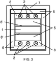
- FIG. 3 shows a schematic of an end view of the example embodiment showing the primary elements inside the general casing.
- the center of the structure is the laser slab crystal 1 surrounded on top and bottom by the cavity filter slabs 5 with gaps 8'.
- the six lamps 2 used to pump the laser crystal 1 are provided outside the cavity filter slabs 5.
- Surrounding these components are four ceramic reflectors 6 which are encased in a housing 7, which can be made of stainless steel.
- the housing 7 in FIG. 3 can be the same type as the housing 3 in FIG. 1 , but that is not a requirement.
- a coolant such as cooling water, which flows to cool the lamps 2 and the slab crystal 1.
- FIG. 4 shows an example embodiment providing water manifolds 10 used to cool the laser.
- Two manifolds 10 cover slots 9 that extend through the external case 7 and through the ceramic reflectors 6'. Water is made to flow in opposite directions through the two slots 9 and through the gaps 8' to cool the central laser slab 1. Water also flows in a separate circuit in the axial direction (in the direction of the pump lamps 2 in Figs. 2 and 3 ) in gaps 8 to cool the pump lamps 2.
- the temperatures of the cooling water for the slab laser crystal 1 and for the pump lamps 2 can be different, since they are on separate circuits (described below) which allow for the slab to operate at an efficient temperature that is higher than that of the lamps.
- holes 11 drilled or otherwise provided in the ceramic reflectors 6' which are placed every few inches along the length of the laser slab 1 and the cavity filter slabs 5. These holes allow for silicon rubber or Teflon bumpers to be used to support the respective slabs and to absorb differences in thermal expansion as the laser elements heat up and thus expand.
- the silicon forms a water seal to keep the water between the slab laser crystal 1 and the cavity filter slabs 5 separate from the different temperature water that is cooling the pump lamps 2.
- the slab laser crystal 1 is comprised of Chromium doped Alexandrite (Cr:BeAl 2 O 4 ), but in another example the slab laser crystal can be comprised of Titanium doped Sapphire.
- the bulk of the slab crystal is made up of the doped material. But it could also subsequently be processed with un-doped sections of Alexandrite crystal (BeAl 2 O 4 ) or for the Ti Sapphire, clear undoped Sapphire on the edges and ends via diffusion bonding to produce clear caps.
- the purpose of the clear cap sections is to reduce the lens distortion due to thermal gradients produced at high pumping powers. These clear caps reduce the distortion effect by a factor of three as the undoped portion has no heat load from left over or un-extracted energy from the gain material.
- the preferred crystal growth method to produce the laser slab crystal would be via the classic Heat Exchange Method (HEM).
- HEM Heat Exchange Method
- This crystal growth technology produces inclusion-free crystals for either of the example gain materials.
- damage free power limits e.g., up to 23 gigawatts per square centimeter can be realized for the Alexandrite material (with similar power handling capability results for the Sapphire material as well).
- Alexandrite crystals can be produced with a power limit of, e.g., 1-1.5 gigawatts per square centimeter radiance for 1 nanosecond pulse lengths.
- a reflective coating such as of silicon dioxide measuring about a micron thick, can be applied to the sides and possibly the edges to act as a reflector for the amplified laser light and to protect the seals where they may overlap a bounce site.
- the diffusion bonded clear caps can be omitted from the sides and the slab crystal can be enclosed on the sides inside the alumina ceramic cavity reflector with the added design element that a dielectric mirror coating be applied to the two sides and the end of the crystal to facilitate the desired reflections of the amplifying beam. This variation would permit a single seal, compressed around the body of the crystal.
- Example pump lamps 2 can utilize Mercury filled (e.g., with a 7 Torr Argon co-fill) clear polished sapphire envelopes or clear fused silica envelopes. Particularly when Sapphire is utilized, Kovar, which is a high nickel alloy that can be used in such lamps as it has a nearly matching expansion coefficient and can be brazed to the envelope using industrially standard techniques. Tungsten electrodes are brazed to the Kovar and are the electrodes establishing the arc in the Mercury.
- Mercury filled e.g., with a 7 Torr Argon co-fill
- Kovar which is a high nickel alloy that can be used in such lamps as it has a nearly matching expansion coefficient and can be brazed to the envelope using industrially standard techniques.
- Tungsten electrodes are brazed to the Kovar and are the electrodes establishing the arc in the Mercury.
- the lamps built and energized in such a manner have an efficiency of, e.g., about 72% for Mercury and, e.g., about 70% for Thallium Iodide.
- These example lamps are best driven with a high frequency AC power supply.
- Such power supplies are commercially available and are referred to as ballasts, with operating frequencies of 40-100 kHz.
- the lamp is sized by choosing the waste heat removal rate (e.g., 240 W/cm 2 surface area using de-ionized water), and scaling to a useful size. For example, a lamp with a bore diameter of about 4.5 mm running at about 135 V/cm will pass about 5.8 amps.
- lamps 1 foot long can be run, e.g., as high as 35 KW or about 1000 watts per cm. However, for long life, the power is reduced to ⁇ 400 watts per cm and the length is shortened. Normal practice is to use a 6 mm diameter fused clear quartz with, e.g., a 2 mm bore with an arc that is about 8-15 cm long. In these lamps energized with an AC power source, there is about a 10% per electrode heat loss and care must be paid to this as unsupportable heat loads can be generated in the electrodes themselves and the immediate adjacent area on the envelope.
- Example cavity filter slabs 5 as shown in FIGs. 1-3 are each made up of a rectangular block crystal comprised of Terbium Fluoride (TbF 3 ) doped with ⁇ 0.1% Samarium, which has absorption bands that encompass most of the ultra-violet spectrum.
- TbF 3 Terbium Fluoride
- the transfer of energy to the Samarium ion is a nearly lossless non-radiation transfer via the crystal matrix.
- the crystal then fluoresces at near the 595 nm peak absorption band of the Alexandrite crystal, converting otherwise wasted UV energy to useful visible light and thereby increases the pump efficiency of the system.
- the spectral output of Mercury lamps at this power level is approximately 1/3 in the UV.
- the use of the cavity filter slabs to recycle as much of the UV radiation energy as possible is desirable for increased efficiency.
- the Terbium Fluoride filter slabs reduce the amount of UV radiation that impinges on the Alexandrite crystal. That radiation, over time, would likely damage the crystal and reduce its transparency which, in turn, limits its usefulness and thus the useful life of the laser device.
- Terbium Garnet with Titanium doped Sapphire gain material Terbium, Cerium, Titanium doped YALO; Gadolinium, Gallium, Terbium, Cerium , Samarium doped YAG; Terbium Fluoride doped with Samarium; and Terbium-Samarium doped Yttrium Lithium Fluoride.
- Terbium Garnet with Titanium doped Sapphire gain material Terbium, Cerium, Titanium doped YALO
- Gadolinium, Gallium, Terbium, Cerium , Samarium doped YAG Terbium Fluoride doped with Samarium
- Terbium-Samarium doped Yttrium Lithium Fluoride Terbium-Samarium doped Yttrium Lithium Fluoride.
- the example ceramic cavity reflector 6, 6' as shown in FIG. 4 can be comprised of a non-degrading ceramic including, for example, a high purity Al 2 O 3 (Alumina) composition.
- the component can be finished with a sealing glaze that allows for a water tight seal on its edges via compressed silicon rubber seal, preferably white or clear.
- the cavity reflector 6 is designed to reflect the light (radiation) from the lamps 2 back into the device to be utilized.
- This reflector 6 is preferably made of an inert (thermally, chemically, and radiation) substance, such as the ceramic material described above.
- the arrangement of the cavity reflectors 6, 6' resembles a rectangular tube with two rectangular slots at each end to facilitate water flow in the open space 8 along the length of the lamps 2. This also cools one face of the cavity filter 5. Additionally, there are square reflector end caps at each end of the pump chamber, in which there are holes allowing the lamps to pass through. There is a separate seal compression plate to allow O-ring seals, of silicon rubber, to be compressed against the lamp walls and the reflector end. At one end there is a rectangular hole for the laser slab to fit through and be sealed via compression O-ring and seal plate.
- FIG. 5 shows the side view of the general shape of the example slab laser crystal 1.
- the shape is defined by a slab width 12, a slab length 13 as measured from the midpoint of each end, a wedge angle acting as a Brewster optical window 14 for the face where the incident and exit beams pass through, and an angle 15 for the reflecting end of the crystal. All four of these parameters are interconnected in the example embodiments, and the slab laser crystal 1 should have a specific set of these parameters for desired functioning.
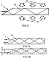
- FIG. 6 shows a preferred example situation where the reflecting angle 15 is provided at 90 degrees and the entrance angle is set by the Brewster angle (for example, the Brewster angle for Alexandrite C axis is 60.06 degrees so the wedge angle 14 of the entrance surface is 29.94 degrees), then the desired slab length is uniquely related to the slab width.
- the length should be such that the beam center impinges on the corner of the slab at the reflecting end so that the exit beam is also on the center line.
- the incident and exit beam 16 are always co-linear.
- the light 20 from the pump lamps enters the top and bottom faces of the slab while the source laser light enters, and the amplified laser light exits, via the Brewster angle surface.
- the exit beam is also displaced in the opposite direction. This is shown in FIG. 7A , where the single incident beam 16 is halfway between the centerline and the edge of the entrance window. Then, if the incident beam (or plurality of beams) is only half of the size of the window as shown by 17 in FIG. 7B , then the exit beam 17' is physically separate from the incident beam 17.
- This configuration solves the problem of the separation of the beams, but limits the beam cross sectional area to be less than half of the size of the slab face.
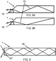
- the front wedge angle 14 is not necessarily required to be set to the complement of the Brewster Angle as in the previous figures. As the angle of the wedge changes, the internal reflection angles of the beam 16 inside the slab changes, and the number of reflections for a given total length changes. Two examples of other incident wedge angles that work for the same length and width are shown in FIGs. 8A and 8B . In the first example of FIG. 8A , the wedge angle 14 is 37.6 degrees, and in the second example of FIG. 8B the wedge angle 14' is 46.2 degrees. It is possible to find a slab length that will work for a wide range of angles. In all such cases, however, the incident and exit beams are on top of each other (coincident) in the opposite directions.
- preferred example embodiments provide for the reflecting surface at the end of the slab to be at an angle different than 90 degrees.
- FIGs. 10A, 10B for two example angles 15 and 15'.
- the end angle 15 is at 88.25 degrees, and this results in the exit beam being separated by 9.41 degrees from the on axis input beam.
- the angle 15' is 91.80 degrees, and the exit beam is separated by 13.50 degrees from the input beam.
- Other angles can be used depending upon the ratio of slab length to slab width, and these two are only shown as examples. This configuration has the desirable features of separating the input and exit beams and allowing for the full aperture to be filled with the incident beam.
- FIG. 11 Another example design using the same materials and general arrangement discussed above but with a slightly different architecture is partially shown in FIG. 11 .
- This variation would permit scaling to much higher power levels.
- the crystal axis is laterally rotated such that the B axis is along the 30 cm dimension.
- a single cavity filter slab 25 that lies between the pump lamps 22 and the laser gain material 21.
- FIG. 12 shows a cross section of the example of one of the segments 30 of an example laser amplifier chain, where the segment 30 incorporates the structure in FIG. 11 .
- This figure shows the laser amplifier slab 21, the cavity filter slab 25, and the array of pump lamps 22. Also shown is the ceramic cavity reflector 26 which covers only one side of the amplifier slab 21, and a stainless steel case 27.
- the cavity reflector 26 is designed to reflect the light (radiation) from the lamps 22 back into the device to be utilized.
- This reflector 26 is preferably made of an inert (thermally, chemically, and radiation) substance, such as a high alumina ceramic, for example.
- the gaps between the amplifier slab 21 and the cavity filter 25 allows for the passage of cooling water as before, and the space around the pump lamps 22 also allows for a separate circuit of cooling water.
- the slabs are held in place by seals 29 that keep the water circuits separate and allow for the thermal expansion of the parts as the temperature increases.
- FIG. 12 Also shown in FIG. 12 is the path of the amplified laser beam.
- the center of the beam is shown by a solid line 16 as it impinges on the surface of the gain crystal 21 at the Brewster Angle.
- the beam refracts (changes angle) as it crosses the surface, is totally reflected off the back surface, and exits at the Brewster Angle.
- the beam is wide, as indicated by the dashed lines 16' and 16" and traverses through the gain medium twice (in and out).
- FIG. 13 shows how the amplifier stages 30 could be combined into an amplifier chain to result in an amplified beam of extremely high power.
- the laser beam 16 alternately passes through each one of the amplifier stages 30 on each side of the beam path. Between each amplifier stage, there is a reflecting surface 31 which traps the pump lamp photons in a cavity until they are absorbed by the laser gain material.
- the laser amplifier could be constructed using the example lasers discussed with respect to FIGs. 1-4 . As the power level increases along the amplifier chain, the amplifiers could change in design to the example configuration shown in FIGs. 11-13 .
- the result is a very high power beam at higher efficiencies than previously possible, up to power handling limit of the exemplified gain materials grown via the HEM method.
- the laser beam is expanded in cross section so this architecture presents a large surface area slab for the beam to interact with.
- the size of the head is limited only by the size of the HEM furnace producing the boule, from which the slab crystal is cut.
- this configuration is made in a 15 cm high by 30 cm long active slab that is 1 cm thick, utilizing a beam cross section of ⁇ 15 cm x 15 cm, it would generate a beam with an enormous amount of peak and average power in a simple and relatively small device.
- the optimum pump lamp size is likely limited to ⁇ 15 cm in length or 6 Kilowatts of power for 6mm diameter 2mm bore envelopes. This limit is due to the 20% heat deposited in the electrodes (corresponding to 10% each end if operated on an AC waveform input).
- the electrode acting as an Anode gets the heat deposition, which occurs on each half cycle. This heat load is manageable in 6 mm diameter quartz tube with a long life. Different dimensions will have different heat removal characteristics and hence different lifetimes.
- the lamp would be constructed with the electrode sections entering at 90 degree arms with the 15 cm arc section between them in an abbreviated "U" configuration.
- This type of lamp would be mounted in staggered parallel sockets through the back reflector such that rows shown in FIG. 11 would be replaced with arrays.
- the arrangement could be such as to achieve uniform pump light intensity with either Thallium Iodide or Mercury arc lamps used with either Alexandrite (Mercury lamp) or Titanium Sapphire (Thallium Iodide lamp) laser slabs.
- a variation of the above described designs is to use Thallium Iodide along with Mercury as the fill in the arc lamp (this changes the spectrum of the pump light, reference Patent 7,061,182 that is incorporated by reference, which if modified to include cooling capability and have higher power loading, could be used as the pump light source to provide a longer lifetime at the cost of lower efficiencies).
- Another option is to use Indium Iodide as the fill inside the sapphire lamps with the Titanium doped sapphire (Ti: Al 2 O 3 ) as the laser slab gain medium.
- Ti: Al 2 O 3 Titanium doped sapphire
- a cavity filter would also be desirable for use as the lamp produces UV light.
- a cavity filter could be avoided for this (Hg/Ar + Thallium Iodide) configuration, since the lamp has an output of 71% at mostly 535 nm. This is a band which is almost at the peak of the Ti: Al 2 O 3 absorption band.
- PLD Pulsed Laser Deposition
- a second beam at a higher repetition rate (e.g., 312.5 kHz) from a Titanium laser operated as an ultra-fast laser is directed at the in-transit plume of ionic atomic deposition material.
- This double laser use would greatly improve the quality of the produced films as any ejected particulate matter would be completely converted to atomic ionized matter by the second laser.
- An extension of this same technology and materials would be reusable heat shield vehicle skin materials, which would be lighter and stronger than current materials combinations.
- At the microscopic level of this same technology would be the PLD deposition of layers of semiconductor materials with subsequent removal of specific areas with subsequent deposition of other semiconductor materials to make a device.
- An illustrative example would be to manufacture diode laser boules with which to make inexpensive diode lasers as one example.
- This would be representative of Micro-electronic circuit or Micro Electro Mechanical devices or MEMs, as this high power pulsed laser technology when used in conjunction with frequency or harmonic conversion devices, would permit generation of previously unheard of power levels in short frequency portions of the spectrum, thereby permitting direct microelectronic device manufacture.
- This technology would be particularly useful for manufacturing Diamond-Like Carbon (DCL) -Microelectronic devices as another example.
- a further example is the depositing of a Boron Arsenide material as a heat spreader material for semiconductor heat control. In this area of application this laser could also be used as an enhanced ion emitter for very high speed molecular beam epitaxy manufacturing machines. This would be in addition to or replacement of the high voltage ion source guns in commercially available machines.
- the use of the Q switched source and the mode locked source (options utilizing nanosecond length pulses, and even picosecond or less pulse lengths acting on the ion source then the ion beam for super atomization would achieve beam currents that would be limited only by the target devices boules ability to accrete the deposited ions into a usable structure rather than being an inherent deposition thickness limit such as 1-10 microns per hour to millimeter or centimeter per hour thicknesses.
- DLC Diamond-Like Carbon
- DLC layers have at least four features that make them important for commercial applications.
- DLC layers have very high thermal conductivity (several times higher than copper) which make them ideal for use as thermal spreaders to remove heat from any surface to which it is attached.
- Third, DLC layers are electrically insulating and have very high breakdown voltage ( ⁇ 10,000 volts per micron thickness).
- Fourth DLC has a very low coefficient of thermal expansion, permitting its use as a substrate for fabricating integrated circuits and microelectronic devices with extremely high operating power as the DLC would conduct the heat of operation away from compact monolithic stacked circuit structures.
- they can be used to provide effective electrical insulation with relatively thin layers or thick wafers/ slabs and stacked monolithic architectured blocks for use in many high voltage or otherwise high electric field density applications, including electrical capacitors for energy storage.
- DLC insulation applied to copper or aluminum wire used in manufacture of various products would permit a DLC insulated device to operate at higher temperatures than are possible with polymer insulation materials.
- the operating temperature limit for conventional polymer- insulated wire devices is about 200 degrees C.
- the DLC coating would function up to its graphitization temperature which begins near 400 degrees C.
- the combination of DLC's thermal conductivity, very low coefficient of thermal expansion, and voltage insulation permits devices to be built that are several times smaller in physical size than their polymer insulated counterparts and yet would still operate at the same power levels..
- DLC coatings created by Pulsed Laser Deposition have been demonstrated on small samples, but the barrier to larger scale commercial applications has been the lack of availability of low cost, higher power lasers like the slab laser disclosed herein.
- PLD Pulsed Laser Deposition
- One implementation is to use the Alexandrite and or Titanium laser, such as of a design disclosed herein, to produce high average power Q switch and or ultrafast pulses being directed at the donor sputter target, with a Titanium Sapphire version producing about 312,500 KHz or greater pulse speeds being used at the same time and being directed at the plume (thus super pulverizing, atomizing and ionizing it) while it is in flight to the substrate.
- This method can be used for any sputter material, and is not limited to graphite as source material.
- Another useful commercial application is in the production of low cost solar cells or integrated circuits by PLD.
- Virtually any material can be deposited on any substrate in any order and thickness with computer controlled deposition and removal of atomic amounts large or small of deposited material.
- the barrier to commercial applications has been the availability of a low cost high power laser source.
- any of the lasers disclosed herein can be used to enable the economical high speed generation of high efficiency multi-layer PV (photo-voltaic) films such as Silicon, Germanium, Gallium Arsenide on Germanium, Gallium Nitride, Gallium Indium Nitride, Gallium Phosphide or any other Gallium Alloy , Included is the claim that any existing semiconductor alloy currently in existence that has been produced by sputtering, Chemical Vapor or ion deposition on any substrate material can be produced with the described laser system or dual laser systems. This technology which would include the high speed large area manufacture of Graphene- a one atom thick sheet of Carbon atoms in single layer or multiple layer configurations grown into a specific shape part.
- PV films can be grown on suitable thermoplastic fabric or foil surfaces. This would provide a path for flexible PV arrays at low manufacturing cost compared to conventional MOCVD (metal organic chemical vapor deposition) methods.
- MOCVD metal organic chemical vapor deposition
- High power lasers have a number of applications in the areas of welding and/or cutting.
- the Q switched version of the slab laser would permit steel plates to be cut that are several to tens of inches thick at accelerated speeds. 20 kW CO 2 lasers are currently being used in shipyards, but 100 kW lasers are rare and very expensive. This would not likely be the case for the slab laser systems as disclosed herein, which can be made more economically.
- a single or combination laser source such as the described pulsed and or continuous wave (such as exemplified by 8,220,0965) used in conjunction as a high powered laser system can also be used for tunneling and/or underground excavation.
- the use of a continuous and/or Q switched pulse train beam as a combined architecture would permit slicing the rock face of a target excavation into thick vertical slabs. If a rectangular section under the slices were to be excavated for the use of an articulated conveyor belt material removal system, and then the cutting beam were to then be directed horizontally several feet above this space on each vertical slice then after the horizontal slices were made then the weight of the slabs of rock, would at some point break the rock free to fall onto an articulated conveyor belt system.
- the pulse length of the lasers can be important to their application. The longer a pulse length of a laser, the more likely that the material being vaporized will contain undesirable particles in the plume. This may happen even with pulses that are several billionths, or nanoseconds, long. However, as one approaches a trillionth of a second long pulse, the atomic relaxation time is approached and this tends to limit the ability of the material to transfer heat energy to adjacent atoms, thus clumps tend to not cool enough to permit accretion and this enhances atomization and reduces particle contamination. That is one reason an explosive can be machined with an ultrafast system and not with a Q-Switched system, with an ultrashort or ultrafast pulse the heat of vaporization leaves with the plume.
- the power scaling law for damage thresholds is the 1 ⁇ 2 power or square root of the pulse length difference, on that basis a 5 GW/cm radiance level for a 1 ns long pulse, would withstand, e.g., 156 MW for a 1 picosecond long pulse.
- the actual pulse length is about 1 ⁇ 2 a nanosecond long and is compressed in a grating pair so as to chirp or spectrally overlap the spectral components. That brings up another problem with ultrafast amplifiers: the speed of light is usually different for different colors in most optical materials, which leads to "dispersion" where the 500 picosecond blue section travels slower than the 500 picosecond red section of the pulse itself. This is one of the most important reasons the average power output of most systems is limited for ultrafast systems and is typically provided under 100 watts.
- An example state of the art system costs $300k, is cooled with liquid nitrogen, and needs a Q switched, frequency doubled pump laser that is 5 times more powerful to get the 100 watts in order to drive it, thus producing a system that is, e.g., about $500k.
- the cost to get 3,600 watts out of the disclosed Ti Sapphire amplifier is in the order of, e.g., about $100,000 at the time of this writing.
- the reason that the manufacturer made the described 100 watt ultrafast system was that it did produce science, of which films of interest were made that Metal Oxide Chemical Vapor Deposition (MOCVD) could not.
- MOCVD Metal Oxide Chemical Vapor Deposition
- a solid state pulse compression technology based on directing a dispersed pulse through a series of high refractive index glass prisms that are arrayed in an antiparallel configuration could be utilized to correct this problem.
- the physical distance is longer for the slower waveform (higher frequency) through the glass and shorter for the faster waveform (lower frequency) the path length difference in air verses glass allows the slow frequency to be compensated by this strategy so it is back where it positionally was in the pulse, as it entered the amplifier.
- This architecture provides a stack that has a mirror at the end of the beam path such that the light is bounced back through the prism stack.
- These stacked prisms can be provided about the size of an amplifier head or longer, which is useful to provide a dispersion compensation head or heads next to the actual power head or heads.
- Figure 14 shows a pulse from the source in a first seed laser 40 through the amplifier 42 and mirrors 48, 47 to its end point in the process chamber 45 and then we will repeat this for a second seed laser41.
- the first seed laser 40 acts as a seed for the ultrafast amplifier chain 42.
- the pulse-length frequency and repetition rate is defined in this component according to the desired application. For example, it can produce a 1 ⁇ 2 nanosecond pulse, with this pulse having, e.g., a 100 nm wide bandwidth 750nm to 850 nm, with pulses of, e.g., 312,500 per second being emitted.
- the florescence output bandwidth of Titanium Sapphire produces light from 650 nm to 1100nm at the same rates as mentioned, allowing operation of the laser at those frequencies, where desirable.
- the amplifier chain can comprise of a series array of amplifier modules such as shown in fig 1 for an example module, where the pulse is introduced into the gain crystal of Titanium Sapphire, as shown in FIGs. 2 & 10A and 10B.
- the laser beam propagates from face to face ( FIG. 10A & 10B ) as it traverses the crystal from end to end and back again, though it will enter and exit at different angles for separation purposes, it is being amplified and dispersed because the speed of light for the red component is faster than the blue component. This causes those sections which are each still 1 ⁇ 2 ns long, to be delayed relative to each other and effectively lengthens the pulse.
- the pulse Upon exiting the first slab, the pulse can be directed into a dispersion compensator or compressor, (described below) which will reverse the displacement effect of the gain crystal such that the now amplified pulse is back to being 1 ⁇ 2 ns long,. This is repeated for each amplification stage until the desired power level is reached, at which point the pulse is compressed with the same kind and design of compensator but the architecture and size is perhaps larger to accommodate the higher energy levels.
- the compression device can be built to produce a pulse that is 5,000 times shorter by a process called chirping. This is where the blue and red sections are translated in time such that they partially extremely overlap and portions of the tail and leading edges of the different colors have been separated such that they destructively interfere, this effect leaves the un overlapped section in the center of the pulse that is at the 1 picosecond length level but does not decrease the energy content of the pulse.
- the final compression stage would be located in the first amplifier 42 housing at the end of an included amplifier chain to output beam 51.
- the emitted beam 51 would proceed to the first beam splitter 48, where a portion 51' of the ultrafast pulse energy would be reflected down to the process or sample chamber 45 to thermalize a substance into the particles in the plume 58 of figure 15 .
- the other portion of beam 51 transmitting through the splitter 45 enters the tripler module 44, where a fraction of the pulse energy is converted, e.g., into photons of 1/3 wavelength or 266nm.
- second seed laser 41 generates a beam 53 with, e.g., a 50ns long pulse that has up to 100 nm bandwidth, at a rate of 13,333 pulses per second (pulse width, repetition rate and bandwidth are chosen by coating engineer to optimize process).
- This beam 53 is directed into the amplifier chain 43 , where the pulse is increased in energy content and exits the amplifier chain 43 via beam path 54 to another mirror 47, where it is directed onto the source material in the sample chamber 45.
- the source sample 57 is shown in FIG. 15 , which is to be vaporized and become the atomized plume 58.
- This laser pulse train in beam 54 does not necessarily have to be compressed, as this effect does not work well on pulses that are longer than 600 picoseconds.
- the dispersion in the Alexandrite gain material does not markedly affect the pulse length and this beam only has to reach the desired power level to be effective at vaporizing the material at the source. Different materials will require different length pulses to optimize this effect which is set in the seed laser for each amplifier chain and material to be deposited.
- FIG.14 shows an example component architecture for the layout of a real world PLD laser source generator that incorporates both the Alexandrite MOPA and the Titanium Sapphire MOPA systems described herein.
- Each has a corresponding seed laser or Master oscillator, 40, 41, which can be a Ti Sapphire and an Alexandrite master oscillator, respectively.
- a master oscillator defines the coherence length, pulse frequency, pulse length and repetition rate for each amplifier chain.
- seed 40 is the ultrafast seed laser, which would produce approximately 1 ⁇ 2 nanosecond (or less) pulses with about 100 nm bandwidth (750nm-850nm) (or a narrower bandwidth) that was, e.g., repeated about every3.2 ⁇ s (or less) or 312,500 times per second (or more). It would most likely be mode locked in (a method of producing very short duration very coherent seed pulse) in order to achieve these short pulses.
- seed 41 would be a source for the Alexandrite amplifier chain 43, and it would produce Q switched, e.g., 50 ns +/-20 ns pulses with a 100 nm or less bandwidth, every, e.g., 75 ⁇ s or 13,333 times per second.
- the bandwidth is a desirable feature for an ultrafast laser, as the pulse length is compressed up to 6000 times by overlapping the spectral components of the blue components and the red components to destructively interfere in the timeframe of each individual pulse. This effect is possible because of the coherence length of the seed pulse (in which the peaks and valleys of the photon's amplitude waves are lined up like marching soldiers).
- This device is a cluster of harmonic frequency conversion crystals in a holder that converts a portion of the chosen beam to become 266 nm photons.
- the unused portion of that beam 51 which is primarily reflected from beam splitter 48, is directed onto the plume so as to thermalize the atoms and particles that are in transit from the ion source to the substrate being coated.
- Beam 52 is the photo-ionizing, e.g., 266 nm ultraviolet beam portion illuminating the sample 59.
- the larger portion that thermalizes or atomizes the plume 58 is via beam 51, and the higher average power, lower repetition rate Alexandrite beam 54 is illuminating the ion source 57.
- the particulars of optimization via angles of incidence irradiance levels on plume, source and substrate are within the film engineer's discretion. All of these parameters are variable by changing the characteristics of the seed lasers and chamber vacuum or partial atmosphere of choice partial pressure.
- an approach as shown in FIGs.14 and 15 can be utilized for semiconductor manufacture (doping and/or depositing layers on semiconductor substrates as workpieces) or to coat various workpiece items with desirable materials, such as diamond or DLC.
- MOPA Master Oscillator Power Amplifier
- Each type of gain crystal- Chromium Doped Chrysoberyl also known as Alexandrite and Titanium doped Sapphire-operates at, and is provided with, a separate Master Oscillator for each type of laser and associated amplifier beam train.
- Each type of gain material has characteristics that favor generation of complimentary pulse lengths and energy levels.
- the Alexandrite MOPA is best utilized generating, e.g., 1-200 nanosecond long pulses, often called Q Switched, in its repetitive pulse train, whereas the Titanium Sapphire MOPA preferentially generates sub-nanosecond pulse lengths that would be suitable for compression to the sub picosecond pulse lengths, often called ultrafast.
- Anti-parallel grating compression or Active mirror prism compression systems would be utilized. Alternately, a Stimulated Brillion Scattering mirror could be used with the compression prisms such that wavefront distortions would be corrected simultaneously.
- a PLD system designer could utilize the two different types of lasers described herein in the same coater system.
- Each type of laser is tunable, so within a standard mirror coating bandwidth, which is typically ⁇ 10% of the centerline frequency, both could easily operate at separate but distinct output frequencies that both would produce polarized outputs.
- High reflectivity polarization beam splitters or mirrors would be used to combine or separate both beams-most likely at the source.
- the Titanium Sapphire crystal has a fluorescence lifetime that is, e.g., about 3.2 ⁇ s vs. the Alexandrite that at typical amplifier design system operating temperature, is, e.g., about 75 ⁇ s though it does have a fluorescence lifetime that ranges from, e.g., 1.5 milliseconds at subfreezing temperatures to, e.g., 75 ⁇ s at 150 degrees Centigrade. This relates to output power and extraction efficiency as the emission cross section changes for Alexandrite at different temperatures. If a gain medium is charged to saturation, a designer can extract a pulse and recharge the gain crystal within this time frame or faster.
- Ti Sapphire lasers are typically pumped, e.g., with 5-200 ns though the average is 50ns+/-20ns, green laser pulses and often the gain section of the Ti Sapphire crystal is saturated so it becomes super radiant.
- the gain crystal will produce a much shorter pulse ( ⁇ 2-5ns) without any special approach, like adding a Q switch and associated electronics.
- pump energy should be added at a rate sufficient to charge the gain material over multiples of that fluorescence timeframe, so in fact they are being run at quasi-CW during the pulse.
- the disclosed design takes advantage of the fact that amplifiers don't need to be charged or pumped to levels that would allow them to run as oscillators, though the Alexandrite device could operate as an oscillator, if desired.
- the lasers are just charged at whatever level the lamps (in the disclosed design) will permit-but because the lamp emission is used as efficiently as disclosed, the amplifiers can have a pulse sent through them to extract that stored energy between the fluorescent timeframe.
- the real world PLD system design will direct the ultrafast and/or Q switched pulse trains onto the plume ( FIG.15 item 51) and perhaps have a Portion of said beam or beams up converted, in harmonic generators, ( FIG. 14 item 44) to reach the short wave UV spectrum so that a designer will have the option to direct the optical power levels and frequencies of interest upon and irradiate the intended plume and or substrate ( FIG.15 items 51 & 54) such that the atomic clumps or particles will be atomized and, ionized or removed and the surface of the substrate being coated will also be photo ionized (and have electrons knocked off) such that this state will increase the accretion rate and structured atomic assembly.
- the temperature dependent emission cross section relates to extraction efficiency, and the damage threshold levels will need to be carefully designed and kept to levels safely under this limit, as the active gain volume in the design favors very high energy content pulse trains that could cause damage if components in the laser path are damaged or disturbed.
Landscapes
- Physics & Mathematics (AREA)
- Electromagnetism (AREA)
- Engineering & Computer Science (AREA)
- Optics & Photonics (AREA)
- Plasma & Fusion (AREA)
- Chemical & Material Sciences (AREA)
- Crystallography & Structural Chemistry (AREA)
- Microelectronics & Electronic Packaging (AREA)
- Condensed Matter Physics & Semiconductors (AREA)
- Power Engineering (AREA)
- Computer Hardware Design (AREA)
- General Physics & Mathematics (AREA)
- Manufacturing & Machinery (AREA)
- Inorganic Chemistry (AREA)
- Organic Chemistry (AREA)
- Metallurgy (AREA)
- Chemical Kinetics & Catalysis (AREA)
- Mechanical Engineering (AREA)
- Materials Engineering (AREA)
- General Chemical & Material Sciences (AREA)
- Toxicology (AREA)
- Health & Medical Sciences (AREA)
- Lasers (AREA)
- Laser Beam Processing (AREA)
Priority Applications (1)
| Application Number | Priority Date | Filing Date | Title |
|---|---|---|---|
| EP17152815.1A EP3185373B1 (en) | 2012-08-03 | 2013-08-01 | Slab laser and amplifier |
Applications Claiming Priority (2)
| Application Number | Priority Date | Filing Date | Title |
|---|---|---|---|
| US13/566,144 US9246299B2 (en) | 2011-08-04 | 2012-08-03 | Slab laser and amplifier |
| PCT/US2013/053166 WO2014022635A1 (en) | 2012-08-03 | 2013-08-01 | Slab laser and amplifier and method of use |
Related Child Applications (2)
| Application Number | Title | Priority Date | Filing Date |
|---|---|---|---|
| EP17152815.1A Division EP3185373B1 (en) | 2012-08-03 | 2013-08-01 | Slab laser and amplifier |
| EP17152815.1A Division-Into EP3185373B1 (en) | 2012-08-03 | 2013-08-01 | Slab laser and amplifier |
Publications (3)
| Publication Number | Publication Date |
|---|---|
| EP2880722A1 EP2880722A1 (en) | 2015-06-10 |
| EP2880722A4 EP2880722A4 (en) | 2016-04-27 |
| EP2880722B1 true EP2880722B1 (en) | 2019-10-09 |
Family
ID=49548573
Family Applications (2)
| Application Number | Title | Priority Date | Filing Date |
|---|---|---|---|
| EP13824767.1A Active EP2880722B1 (en) | 2012-08-03 | 2013-08-01 | Slab laser and amplifier and method of use |
| EP17152815.1A Active EP3185373B1 (en) | 2012-08-03 | 2013-08-01 | Slab laser and amplifier |
Family Applications After (1)
| Application Number | Title | Priority Date | Filing Date |
|---|---|---|---|
| EP17152815.1A Active EP3185373B1 (en) | 2012-08-03 | 2013-08-01 | Slab laser and amplifier |
Country Status (9)
| Country | Link |
|---|---|
| US (5) | US9246299B2 (ja) |
| EP (2) | EP2880722B1 (ja) |
| JP (2) | JP6415435B2 (ja) |
| CN (1) | CN104604049B (ja) |
| BR (1) | BR112015002090B1 (ja) |
| CA (1) | CA2879746A1 (ja) |
| IN (1) | IN2015DN00970A (ja) |
| RU (1) | RU2650807C9 (ja) |
| WO (1) | WO2014022635A1 (ja) |
Families Citing this family (100)
| Publication number | Priority date | Publication date | Assignee | Title |
|---|---|---|---|---|
| WO2014120807A1 (en) * | 2013-01-29 | 2014-08-07 | The Trustees Of Boston College | High thermal conductivity materials for thermal management applications |
| KR102193150B1 (ko) * | 2013-12-27 | 2020-12-21 | 삼성디스플레이 주식회사 | 증착 장치 및 이를 이용한 증착량 제어 방법 |
| KR102192983B1 (ko) * | 2014-01-15 | 2020-12-21 | 삼성디스플레이 주식회사 | 증착 장치 및 이를 이용한 증착 속도 산출 방법 |
| ES2770053T3 (es) | 2014-05-16 | 2020-06-30 | Divergent Tech Inc | Nodos formados modulares para chasis de vehículo y sus métodos de uso |
| RU2569904C1 (ru) * | 2014-06-25 | 2015-12-10 | Владимир Валентинович Павлов | Лазерное устройство с пластинчатым оптическим элементом |
| EP3164260B1 (en) | 2014-07-02 | 2021-07-28 | Divergent Technologies, Inc. | Vehicle chassis |
| JP6593845B2 (ja) * | 2014-08-29 | 2019-10-23 | 国立研究開発法人産業技術総合研究所 | 有機材料膜又は有機無機複合材料膜のレーザー蒸着方法、レーザー蒸着装置 |
| US10220471B2 (en) | 2015-10-14 | 2019-03-05 | Lawrence Livermore National Security, Llc | Spatter reduction laser scanning strategy in selective laser melting |
| JP7499562B2 (ja) | 2015-10-30 | 2024-06-14 | シューラット テクノロジーズ,インク. | 付加製造システム及び方法 |
| WO2017132664A1 (en) | 2016-01-28 | 2017-08-03 | Seurat Technologies, Inc. | Additive manufacturing, spatial heat treating system and method |
| EP3995277A1 (en) * | 2016-01-29 | 2022-05-11 | Seurat Technologies, Inc. | System for additive manufacturing |
| DE102016108474A1 (de) | 2016-05-09 | 2017-11-09 | Deutsches Zentrum für Luft- und Raumfahrt e.V. | Festkörper, Laserverstärkungssystem und Festkörperlaser |
| WO2017204358A1 (ja) * | 2016-05-27 | 2017-11-30 | 富士フイルム株式会社 | 固体レーザ装置 |
| JP2019527138A (ja) | 2016-06-09 | 2019-09-26 | ダイバージェント テクノロジーズ, インコーポレイテッドDivergent Technologies, Inc. | アークおよびノードの設計ならびに製作のためのシステムおよび方法 |
| CN106602391B (zh) * | 2016-12-09 | 2019-04-30 | 中国人民解放军海军航空工程学院 | 一种具备波前畸变自校正能力的板条激光模块 |
| US11155005B2 (en) | 2017-02-10 | 2021-10-26 | Divergent Technologies, Inc. | 3D-printed tooling and methods for producing same |
| US10759090B2 (en) | 2017-02-10 | 2020-09-01 | Divergent Technologies, Inc. | Methods for producing panels using 3D-printed tooling shells |
| US10898968B2 (en) | 2017-04-28 | 2021-01-26 | Divergent Technologies, Inc. | Scatter reduction in additive manufacturing |
| KR102626294B1 (ko) | 2017-05-11 | 2024-01-17 | 쇠라 테크널러지스 인코포레이티드 | 적층 가공을 위한 패턴화된 광의 스위치야드 빔 라우팅 |
| US10703419B2 (en) | 2017-05-19 | 2020-07-07 | Divergent Technologies, Inc. | Apparatus and methods for joining panels |
| US11358337B2 (en) | 2017-05-24 | 2022-06-14 | Divergent Technologies, Inc. | Robotic assembly of transport structures using on-site additive manufacturing |
| US11123973B2 (en) | 2017-06-07 | 2021-09-21 | Divergent Technologies, Inc. | Interconnected deflectable panel and node |
| US10919230B2 (en) | 2017-06-09 | 2021-02-16 | Divergent Technologies, Inc. | Node with co-printed interconnect and methods for producing same |
| US10781846B2 (en) | 2017-06-19 | 2020-09-22 | Divergent Technologies, Inc. | 3-D-printed components including fasteners and methods for producing same |
| US10994876B2 (en) | 2017-06-30 | 2021-05-04 | Divergent Technologies, Inc. | Automated wrapping of components in transport structures |
| US11022375B2 (en) | 2017-07-06 | 2021-06-01 | Divergent Technologies, Inc. | Apparatus and methods for additively manufacturing microtube heat exchangers |
| US10895315B2 (en) | 2017-07-07 | 2021-01-19 | Divergent Technologies, Inc. | Systems and methods for implementing node to node connections in mechanized assemblies |
| US10751800B2 (en) | 2017-07-25 | 2020-08-25 | Divergent Technologies, Inc. | Methods and apparatus for additively manufactured exoskeleton-based transport structures |
| US10940609B2 (en) | 2017-07-25 | 2021-03-09 | Divergent Technologies, Inc. | Methods and apparatus for additively manufactured endoskeleton-based transport structures |
| US10605285B2 (en) | 2017-08-08 | 2020-03-31 | Divergent Technologies, Inc. | Systems and methods for joining node and tube structures |
| US10357959B2 (en) | 2017-08-15 | 2019-07-23 | Divergent Technologies, Inc. | Methods and apparatus for additively manufactured identification features |
| US11306751B2 (en) | 2017-08-31 | 2022-04-19 | Divergent Technologies, Inc. | Apparatus and methods for connecting tubes in transport structures |
| US10960611B2 (en) | 2017-09-06 | 2021-03-30 | Divergent Technologies, Inc. | Methods and apparatuses for universal interface between parts in transport structures |
| US11292058B2 (en) | 2017-09-12 | 2022-04-05 | Divergent Technologies, Inc. | Apparatus and methods for optimization of powder removal features in additively manufactured components |
| US10668816B2 (en) | 2017-10-11 | 2020-06-02 | Divergent Technologies, Inc. | Solar extended range electric vehicle with panel deployment and emitter tracking |
| US10814564B2 (en) | 2017-10-11 | 2020-10-27 | Divergent Technologies, Inc. | Composite material inlay in additively manufactured structures |
| US10752986B2 (en) * | 2017-10-30 | 2020-08-25 | Savannah River Nuclear Solutions, Llc | Method of manufacturing a three-dimensional carbon structure |
| US11786971B2 (en) | 2017-11-10 | 2023-10-17 | Divergent Technologies, Inc. | Structures and methods for high volume production of complex structures using interface nodes |
| US10926599B2 (en) | 2017-12-01 | 2021-02-23 | Divergent Technologies, Inc. | Suspension systems using hydraulic dampers |
| US11110514B2 (en) | 2017-12-14 | 2021-09-07 | Divergent Technologies, Inc. | Apparatus and methods for connecting nodes to tubes in transport structures |
| US11085473B2 (en) | 2017-12-22 | 2021-08-10 | Divergent Technologies, Inc. | Methods and apparatus for forming node to panel joints |
| US11534828B2 (en) | 2017-12-27 | 2022-12-27 | Divergent Technologies, Inc. | Assembling structures comprising 3D printed components and standardized components utilizing adhesive circuits |
| US11420262B2 (en) | 2018-01-31 | 2022-08-23 | Divergent Technologies, Inc. | Systems and methods for co-casting of additively manufactured interface nodes |
| US10751934B2 (en) | 2018-02-01 | 2020-08-25 | Divergent Technologies, Inc. | Apparatus and methods for additive manufacturing with variable extruder profiles |
| US11224943B2 (en) | 2018-03-07 | 2022-01-18 | Divergent Technologies, Inc. | Variable beam geometry laser-based powder bed fusion |
| US11267236B2 (en) | 2018-03-16 | 2022-03-08 | Divergent Technologies, Inc. | Single shear joint for node-to-node connections |
| US11872689B2 (en) | 2018-03-19 | 2024-01-16 | Divergent Technologies, Inc. | End effector features for additively manufactured components |
| US11254381B2 (en) | 2018-03-19 | 2022-02-22 | Divergent Technologies, Inc. | Manufacturing cell based vehicle manufacturing system and method |
| US11408216B2 (en) | 2018-03-20 | 2022-08-09 | Divergent Technologies, Inc. | Systems and methods for co-printed or concurrently assembled hinge structures |
| US11613078B2 (en) | 2018-04-20 | 2023-03-28 | Divergent Technologies, Inc. | Apparatus and methods for additively manufacturing adhesive inlet and outlet ports |
| US11214317B2 (en) | 2018-04-24 | 2022-01-04 | Divergent Technologies, Inc. | Systems and methods for joining nodes and other structures |
| US10682821B2 (en) | 2018-05-01 | 2020-06-16 | Divergent Technologies, Inc. | Flexible tooling system and method for manufacturing of composite structures |
| US11020800B2 (en) | 2018-05-01 | 2021-06-01 | Divergent Technologies, Inc. | Apparatus and methods for sealing powder holes in additively manufactured parts |
| US11389816B2 (en) | 2018-05-09 | 2022-07-19 | Divergent Technologies, Inc. | Multi-circuit single port design in additively manufactured node |
| US10691104B2 (en) | 2018-05-16 | 2020-06-23 | Divergent Technologies, Inc. | Additively manufacturing structures for increased spray forming resolution or increased fatigue life |
| US11590727B2 (en) | 2018-05-21 | 2023-02-28 | Divergent Technologies, Inc. | Custom additively manufactured core structures |
| US11441586B2 (en) | 2018-05-25 | 2022-09-13 | Divergent Technologies, Inc. | Apparatus for injecting fluids in node based connections |
| US11035511B2 (en) | 2018-06-05 | 2021-06-15 | Divergent Technologies, Inc. | Quick-change end effector |
| US11292056B2 (en) | 2018-07-06 | 2022-04-05 | Divergent Technologies, Inc. | Cold-spray nozzle |
| CN108963740B (zh) * | 2018-07-09 | 2019-08-09 | 北京空间机电研究所 | 一种板条固体激光器泵浦增益模块 |
| US11269311B2 (en) | 2018-07-26 | 2022-03-08 | Divergent Technologies, Inc. | Spray forming structural joints |
| US10836120B2 (en) | 2018-08-27 | 2020-11-17 | Divergent Technologies, Inc . | Hybrid composite structures with integrated 3-D printed elements |
| US11433557B2 (en) | 2018-08-28 | 2022-09-06 | Divergent Technologies, Inc. | Buffer block apparatuses and supporting apparatuses |
| US11826953B2 (en) | 2018-09-12 | 2023-11-28 | Divergent Technologies, Inc. | Surrogate supports in additive manufacturing |
| US11072371B2 (en) | 2018-10-05 | 2021-07-27 | Divergent Technologies, Inc. | Apparatus and methods for additively manufactured structures with augmented energy absorption properties |
| US11260582B2 (en) | 2018-10-16 | 2022-03-01 | Divergent Technologies, Inc. | Methods and apparatus for manufacturing optimized panels and other composite structures |
| US11504912B2 (en) | 2018-11-20 | 2022-11-22 | Divergent Technologies, Inc. | Selective end effector modular attachment device |
| USD911222S1 (en) | 2018-11-21 | 2021-02-23 | Divergent Technologies, Inc. | Vehicle and/or replica |
| EP3894108A4 (en) | 2018-12-14 | 2022-08-17 | Seurat Technologies, Inc. | ADDITIVE MANUFACTURING SYSTEM FOR CREATING OBJECTS FROM POWDER USING A HIGH FLUX LASER FOR TWO-DIMENSIONAL PRINTING |
| US11449021B2 (en) | 2018-12-17 | 2022-09-20 | Divergent Technologies, Inc. | Systems and methods for high accuracy fixtureless assembly |
| US10663110B1 (en) | 2018-12-17 | 2020-05-26 | Divergent Technologies, Inc. | Metrology apparatus to facilitate capture of metrology data |
| US11529741B2 (en) | 2018-12-17 | 2022-12-20 | Divergent Technologies, Inc. | System and method for positioning one or more robotic apparatuses |
| CN116021031A (zh) | 2018-12-19 | 2023-04-28 | 速尔特技术有限公司 | 使用脉冲调制的激光进行二维打印的增材制造系统 |
| US11885000B2 (en) | 2018-12-21 | 2024-01-30 | Divergent Technologies, Inc. | In situ thermal treatment for PBF systems |
| JP7341673B2 (ja) * | 2019-02-27 | 2023-09-11 | 三菱重工業株式会社 | レーザ装置 |
| US11203240B2 (en) | 2019-04-19 | 2021-12-21 | Divergent Technologies, Inc. | Wishbone style control arm assemblies and methods for producing same |
| CN112886378A (zh) * | 2019-11-29 | 2021-06-01 | 山东大学 | 一种590nm波段拉曼倍频光源泵浦的翠绿宝石被动锁模激光器 |
| EP4088289A4 (en) * | 2020-01-06 | 2024-03-20 | Battelle Energy Alliance, LLC | SOLID-STATE NUCLEAR PUMPED LASER EMISSION SENSORS FOR MEASURING BATTERY REACTOR POWER AND FLOW, DIRECT ENERGY CONVERSION, AND ASSOCIATED METHODS |
| US11912339B2 (en) | 2020-01-10 | 2024-02-27 | Divergent Technologies, Inc. | 3-D printed chassis structure with self-supporting ribs |
| US11590703B2 (en) | 2020-01-24 | 2023-02-28 | Divergent Technologies, Inc. | Infrared radiation sensing and beam control in electron beam additive manufacturing |
| US11884025B2 (en) | 2020-02-14 | 2024-01-30 | Divergent Technologies, Inc. | Three-dimensional printer and methods for assembling parts via integration of additive and conventional manufacturing operations |
| US11479015B2 (en) | 2020-02-14 | 2022-10-25 | Divergent Technologies, Inc. | Custom formed panels for transport structures and methods for assembling same |
| CN111293579B (zh) * | 2020-02-21 | 2021-07-27 | 中国航空制造技术研究院 | 一种用于板条激光晶体的双面水冷装置 |
| US11421577B2 (en) | 2020-02-25 | 2022-08-23 | Divergent Technologies, Inc. | Exhaust headers with integrated heat shielding and thermal syphoning |
| US11535322B2 (en) | 2020-02-25 | 2022-12-27 | Divergent Technologies, Inc. | Omni-positional adhesion device |
| US11413686B2 (en) | 2020-03-06 | 2022-08-16 | Divergent Technologies, Inc. | Methods and apparatuses for sealing mechanisms for realizing adhesive connections with additively manufactured components |
| US12088055B2 (en) * | 2020-04-10 | 2024-09-10 | Seurat Technologies, Inc. | Fluid edge cladding for spectroscopic absorption of laser emissions and amplified spontaneous emission |
| US20210316502A1 (en) * | 2020-04-10 | 2021-10-14 | Seurat Technologies, Inc. | High Throughput Additive Manufacturing System Supporting Absorption Of Amplified Spontaneous Emission In Laser Amplifiers |
| US11850804B2 (en) | 2020-07-28 | 2023-12-26 | Divergent Technologies, Inc. | Radiation-enabled retention features for fixtureless assembly of node-based structures |
| US11806941B2 (en) | 2020-08-21 | 2023-11-07 | Divergent Technologies, Inc. | Mechanical part retention features for additively manufactured structures |
| US12083596B2 (en) | 2020-12-21 | 2024-09-10 | Divergent Technologies, Inc. | Thermal elements for disassembly of node-based adhesively bonded structures |
| US11872626B2 (en) | 2020-12-24 | 2024-01-16 | Divergent Technologies, Inc. | Systems and methods for floating pin joint design |
| US11947335B2 (en) | 2020-12-30 | 2024-04-02 | Divergent Technologies, Inc. | Multi-component structure optimization for combining 3-D printed and commercially available parts |
| US11928966B2 (en) | 2021-01-13 | 2024-03-12 | Divergent Technologies, Inc. | Virtual railroad |
| RU2757834C1 (ru) * | 2021-01-28 | 2021-10-21 | Акционерное Общество "Наука И Инновации" | Съемная кассета для усилительного модуля |
| WO2022192465A1 (en) | 2021-03-09 | 2022-09-15 | Divergent Technologies, Inc. | Rotational additive manufacturing systems and methods |
| US12090551B2 (en) | 2021-04-23 | 2024-09-17 | Divergent Technologies, Inc. | Removal of supports, and other materials from surface, and within hollow 3D printed parts |
| US11865617B2 (en) | 2021-08-25 | 2024-01-09 | Divergent Technologies, Inc. | Methods and apparatuses for wide-spectrum consumption of output of atomization processes across multi-process and multi-scale additive manufacturing modalities |
| CN113991397B (zh) * | 2021-10-28 | 2023-06-27 | 河北工业大学 | 一种固体激光阵列放大器 |
| CN114779373B (zh) * | 2022-03-14 | 2024-03-26 | 清华大学 | 光功率分束器及其制备方法 |
Family Cites Families (81)
| Publication number | Priority date | Publication date | Assignee | Title |
|---|---|---|---|---|
| US3631362A (en) | 1968-08-27 | 1971-12-28 | Gen Electric | Face-pumped, face-cooled laser device |
| US3633126A (en) | 1969-04-17 | 1972-01-04 | Gen Electric | Multiple internal reflection face-pumped laser |
| US3766490A (en) * | 1972-03-14 | 1973-10-16 | Us Army | Lu:nd:yag laser system and material |
| AU1363076A (en) * | 1976-05-04 | 1977-11-10 | Ward H | Laser amplification |
| US4769823A (en) | 1985-12-31 | 1988-09-06 | General Electric Company | Laser system with trivalent chromium doped aluminum tungstate fluorescent converter |
| US4794616A (en) * | 1985-12-31 | 1988-12-27 | General Electric Company | Laser system with solid state fluorescent converter matrix having distributed fluorescent converter particles |
| US4734917A (en) * | 1985-12-31 | 1988-03-29 | General Electric Company | Fluorescent converter pumped cavity for laser system |
| US4838243A (en) | 1987-04-17 | 1989-06-13 | Stephen Kuber | Chimney cleanout tee cap lock |
| US4858243A (en) * | 1987-06-12 | 1989-08-15 | Raycon Corporation | Laser pumping cavity |
| JP2586110B2 (ja) * | 1988-06-30 | 1997-02-26 | 三菱電機株式会社 | 固体レーザ装置 |
| IL87370A (en) | 1988-08-08 | 1992-03-29 | Electro Optics Ind Ltd | Laser pumping cavity |
| JPH03190293A (ja) | 1989-12-20 | 1991-08-20 | Hoya Corp | スラブ型レーザ媒体 |
| JPH04137573A (ja) | 1990-09-27 | 1992-05-12 | Hoya Corp | コンポジットスラブレーザ媒体及びレーザ装置 |
| US5659567A (en) * | 1992-02-19 | 1997-08-19 | Roberts; Rosemary Szewjkowski | Microwave-driven UV light source and solid-state laser |
| JPH05254879A (ja) * | 1992-03-06 | 1993-10-05 | Seiko Epson Corp | 蛍光ガラス及びそれを用いたレーザー装置 |
| JPH06125125A (ja) * | 1992-05-12 | 1994-05-06 | Mitsubishi Electric Corp | 固体レーザ装置 |
| DE4220158A1 (de) | 1992-06-19 | 1993-12-23 | Battelle Institut E V | Verfahren zur selektiven Abscheidung von Aluminiumstrukturen aus der Gasphase |
| US5299220A (en) | 1992-09-08 | 1994-03-29 | Brown David C | Slab laser |
| US5305345A (en) | 1992-09-25 | 1994-04-19 | The United States Of America As Represented By The United States Department Of Energy | Zigzag laser with reduced optical distortion |
| JPH06350171A (ja) * | 1993-04-15 | 1994-12-22 | Fuji Electric Co Ltd | 固体レーザ装置および積分球 |
| US5581573A (en) * | 1993-04-15 | 1996-12-03 | Fuji Electric Co., Ltd. | Solid-state laser device with diffused-light excitation, and integrating sphere |
| WO1994024734A1 (en) | 1993-04-21 | 1994-10-27 | The Commonwealth Of Australia | Diode pumped slab laser |
| US5394427A (en) | 1994-04-29 | 1995-02-28 | Cutting Edge Optronics, Inc. | Housing for a slab laser pumped by a close-coupled light source |
| US5553092A (en) * | 1994-05-17 | 1996-09-03 | Alliedsignal Inc. | Solid state laser with integral optical diffuser plate to homogenize optical pumping |
| US5479430A (en) | 1995-02-07 | 1995-12-26 | The Board Of Trustees Of The Leland Stanford Junior University | Protective coating for solid state slab lasers |
| JPH0927646A (ja) * | 1995-07-12 | 1997-01-28 | Hitachi Ltd | スラブレーザ |
| DE19541020A1 (de) | 1995-11-03 | 1997-05-07 | Daimler Benz Ag | Laserverstärkersystem |
| JPH09199781A (ja) * | 1996-01-16 | 1997-07-31 | Nec Corp | レーザ増幅器 |
| US5832016A (en) | 1997-01-29 | 1998-11-03 | Northrop Grumman Corporation | Slab laser assembly |
| RU8168U1 (ru) | 1997-11-28 | 1998-10-16 | Валерий Геннадиевич Полушкин | Активный лазерный элемент с волноводным режимом работы |
| US6014391A (en) | 1997-12-19 | 2000-01-11 | Raytheon Company | Thermally improved slab laser pump cavity apparatus with integral concentrator and method of making same |
| JPH11220191A (ja) * | 1998-01-29 | 1999-08-10 | Miyachi Technos Corp | 固体レーザ装置 |
| US6134258A (en) * | 1998-03-25 | 2000-10-17 | The Board Of Trustees Of The Leland Stanford Junior University | Transverse-pumped sLAB laser/amplifier |
| US6347101B1 (en) | 1998-04-16 | 2002-02-12 | 3D Systems, Inc. | Laser with absorption optimized pumping of a gain medium |
| JP3154689B2 (ja) * | 1998-05-26 | 2001-04-09 | 三菱重工業株式会社 | 半導体レーザ励起スラブ固体レーザ装置 |
| US6268956B1 (en) | 1998-07-07 | 2001-07-31 | Trw Inc. | End pumped zig-zag slab laser gain medium |
| US6219361B1 (en) | 1999-06-21 | 2001-04-17 | Litton Systems, Inc. | Side pumped, Q-switched microlaser |
| US6356575B1 (en) | 1999-07-06 | 2002-03-12 | Raytheon Company | Dual cavity multifunction laser system |
| US6373866B1 (en) | 2000-01-26 | 2002-04-16 | Lumenis Inc. | Solid-state laser with composite prismatic gain-region |
| US6738399B1 (en) | 2001-05-17 | 2004-05-18 | The United States Of America As Represented By The United States Department Of Energy | Microchannel cooled edge cladding to establish an adiabatic boundary condition in a slab laser |
| US7065121B2 (en) | 2001-07-24 | 2006-06-20 | Gsi Group Ltd. | Waveguide architecture, waveguide devices for laser processing and beam control, and laser processing applications |
| US20030138021A1 (en) | 2001-10-25 | 2003-07-24 | Norman Hodgson | Diode-pumped solid-state thin slab laser |
| AU2003235235B2 (en) * | 2002-04-26 | 2007-10-25 | Sumitomo Electric Industries, Ltd. | Process for producing oxide superconductive thin-film |
| US7065109B2 (en) * | 2002-05-08 | 2006-06-20 | Melles Griot Inc. | Laser with narrow bandwidth antireflection filter for frequency selection |
| TWI270918B (en) * | 2003-05-27 | 2007-01-11 | Ip2H Ag | Light source and method for supplying a transport function to a chemical element in a light source |
| US7257302B2 (en) * | 2003-06-03 | 2007-08-14 | Imra America, Inc. | In-line, high energy fiber chirped pulse amplification system |
| US7520790B2 (en) * | 2003-09-19 | 2009-04-21 | Semiconductor Energy Laboratory Co., Ltd. | Display device and manufacturing method of display device |
| JP4754795B2 (ja) * | 2003-09-19 | 2011-08-24 | 株式会社半導体エネルギー研究所 | 表示装置及び表示装置の作製方法 |
| US7388895B2 (en) | 2003-11-21 | 2008-06-17 | Tsinghua University | Corner-pumping method and gain module for high power slab laser |
| US7376160B2 (en) | 2003-11-24 | 2008-05-20 | Raytheon Company | Slab laser and method with improved and directionally homogenized beam quality |
| JP3899411B2 (ja) | 2004-02-19 | 2007-03-28 | 独立行政法人情報通信研究機構 | 3つの反射面による多重反射で構成される光路を用いたスラブ型固体レーザ媒体、またはスラブ型非線形光学媒体 |
| JP2005294625A (ja) * | 2004-04-01 | 2005-10-20 | Sony Corp | 成膜装置 |
| US7123634B2 (en) | 2004-05-07 | 2006-10-17 | Northrop Grumman Corporation | Zig-zag laser amplifier with polarization controlled reflectors |
| US7039087B2 (en) | 2004-05-13 | 2006-05-02 | The United States Of America As Represented By The Department Of The Army | End pumped slab laser cavity |
| US7879410B2 (en) * | 2004-06-09 | 2011-02-01 | Imra America, Inc. | Method of fabricating an electrochemical device using ultrafast pulsed laser deposition |
| GB0418333D0 (en) | 2004-08-17 | 2004-09-22 | Cambridge Display Tech Ltd | Enhanced emission of light from organic light emitting diodes |
| US7280571B2 (en) | 2004-11-23 | 2007-10-09 | Northrop Grumman Corporation | Scalable zig-zag laser amplifier |
| US7590160B2 (en) | 2004-11-26 | 2009-09-15 | Manni Jeffrey G | High-gain diode-pumped laser amplifier |
| US7505499B2 (en) | 2004-12-15 | 2009-03-17 | Panasonic Corporation | Slab laser amplifier with parasitic oscillation suppression |
| US8599898B2 (en) | 2004-12-22 | 2013-12-03 | Universal Laser Systems, Inc. | Slab laser with composite resonator and method of producing high-energy laser radiation |
| FI20050216A0 (fi) * | 2005-02-23 | 2005-02-23 | Ruuttu Jari | Menetelmä valmistaa timanttia, muita jalokiviä, kuten safiiria, rubiinia jne. ja suorittaa näillä pinnoituksia sekä suorittaa pinnoituksia muilla aineilla, kuten boriideillä, oksideillä, nitrideillä jne. |
| US7542489B2 (en) | 2005-03-25 | 2009-06-02 | Pavilion Integration Corporation | Injection seeding employing continuous wavelength sweeping for master-slave resonance |
| JP2006307251A (ja) * | 2005-04-27 | 2006-11-09 | Kobe Univ | ダイヤモンドライクカーボン薄膜の作製方法 |
| US7386019B2 (en) * | 2005-05-23 | 2008-06-10 | Time-Bandwidth Products Ag | Light pulse generating apparatus and method |
| JP4883503B2 (ja) * | 2005-06-21 | 2012-02-22 | 独立行政法人情報通信研究機構 | 多重光路の固体スラブレーザロッドまたは非線形光学結晶を用いたレーザ装置 |
| US7391558B2 (en) | 2005-10-19 | 2008-06-24 | Raytheon Company | Laser amplifier power extraction enhancement system and method |
| US7860142B2 (en) * | 2006-02-07 | 2010-12-28 | Raytheon Company | Laser with spectral converter |
| KR20070117738A (ko) * | 2006-06-09 | 2007-12-13 | 삼성전자주식회사 | 표시기판의 리페어 방법 및 이에 의해 리페어된 표시기판 |
| US7929579B2 (en) | 2006-08-02 | 2011-04-19 | Cynosure, Inc. | Picosecond laser apparatus and methods for its operation and use |
| US20080089369A1 (en) | 2006-10-16 | 2008-04-17 | Pavilion Integration Corporation | Injection seeding employing continuous wavelength sweeping for master-slave resonance |
| US20080116183A1 (en) * | 2006-11-21 | 2008-05-22 | Palo Alto Research Center Incorporated | Light Scanning Mechanism For Scan Displacement Invariant Laser Ablation Apparatus |
| RU2346380C1 (ru) * | 2007-07-17 | 2009-02-10 | Общество с ограниченной ответственностью "Мармирус" | Емкостной генератор тока |
| EP2065485B1 (en) * | 2007-11-21 | 2011-05-18 | OTB Solar B.V. | Method and system for continuous or semi-continuous laser deposition. |
| US7633979B2 (en) | 2008-02-12 | 2009-12-15 | Pavilion Integration Corporation | Method and apparatus for producing UV laser from all-solid-state system |
| JP5305758B2 (ja) | 2008-06-30 | 2013-10-02 | 株式会社東芝 | 半導体発光装置 |
| US7822091B2 (en) | 2008-07-14 | 2010-10-26 | Lockheed Martin Corporation | Inverted composite slab sandwich laser gain medium |
| JP4910010B2 (ja) | 2009-03-24 | 2012-04-04 | 株式会社東芝 | 半導体発光装置 |
| TWM370095U (en) | 2009-06-30 | 2009-12-01 | Acpa Energy Conversion Devices Co Ltd | Wave length modulating apparatus for light source |
| US9181477B2 (en) * | 2010-10-01 | 2015-11-10 | The Trustees Of The University Of Pennsylvania | Morphologically and size uniform monodisperse particles and their shape-directed self-assembly |
| US8908737B2 (en) | 2011-04-04 | 2014-12-09 | Coherent, Inc. | Transition-metal-doped thin-disk laser |
| US8774236B2 (en) | 2011-08-17 | 2014-07-08 | Veralas, Inc. | Ultraviolet fiber laser system |
-
2012
- 2012-08-03 US US13/566,144 patent/US9246299B2/en not_active Expired - Fee Related
-
2013
- 2013-08-01 IN IN970DEN2015 patent/IN2015DN00970A/en unknown
- 2013-08-01 EP EP13824767.1A patent/EP2880722B1/en active Active
- 2013-08-01 US US14/418,500 patent/US9287112B2/en not_active Expired - Fee Related
- 2013-08-01 JP JP2015525585A patent/JP6415435B2/ja not_active Expired - Fee Related
- 2013-08-01 BR BR112015002090-9A patent/BR112015002090B1/pt not_active IP Right Cessation
- 2013-08-01 WO PCT/US2013/053166 patent/WO2014022635A1/en active Application Filing
- 2013-08-01 CN CN201380046502.1A patent/CN104604049B/zh not_active Expired - Fee Related
- 2013-08-01 CA CA2879746A patent/CA2879746A1/en not_active Abandoned
- 2013-08-01 EP EP17152815.1A patent/EP3185373B1/en active Active
- 2013-08-01 RU RU2015102528A patent/RU2650807C9/ru active
-
2015
- 2015-10-23 US US14/921,285 patent/US10777960B2/en active Active
-
2016
- 2016-03-14 US US15/068,950 patent/US9525262B2/en active Active
- 2016-11-10 US US15/348,321 patent/US20170070022A1/en not_active Abandoned
-
2018
- 2018-05-15 JP JP2018093437A patent/JP6743087B2/ja not_active Expired - Fee Related
Non-Patent Citations (1)
| Title |
|---|
| None * |
Also Published As
| Publication number | Publication date |
|---|---|
| JP2015528217A (ja) | 2015-09-24 |
| EP3185373B1 (en) | 2021-04-07 |
| JP6415435B2 (ja) | 2018-10-31 |
| RU2015102528A (ru) | 2016-09-20 |
| JP6743087B2 (ja) | 2020-08-19 |
| IN2015DN00970A (ja) | 2015-06-12 |
| US20150311064A1 (en) | 2015-10-29 |
| US9246299B2 (en) | 2016-01-26 |
| EP3185373A1 (en) | 2017-06-28 |
| US20160043524A1 (en) | 2016-02-11 |
| CA2879746A1 (en) | 2014-02-06 |
| RU2650807C9 (ru) | 2018-09-06 |
| BR112015002090A2 (pt) | 2017-07-04 |
| RU2650807C2 (ru) | 2018-04-17 |
| EP2880722A4 (en) | 2016-04-27 |
| CN104604049B (zh) | 2019-08-13 |
| US10777960B2 (en) | 2020-09-15 |
| US9525262B2 (en) | 2016-12-20 |
| US20170070022A1 (en) | 2017-03-09 |
| JP2018164090A (ja) | 2018-10-18 |
| WO2014022635A1 (en) | 2014-02-06 |
| US9287112B2 (en) | 2016-03-15 |
| US20130301662A1 (en) | 2013-11-14 |
| US20160211637A1 (en) | 2016-07-21 |
| BR112015002090B1 (pt) | 2021-05-25 |
| CN104604049A (zh) | 2015-05-06 |
| EP2880722A1 (en) | 2015-06-10 |
Similar Documents
| Publication | Publication Date | Title |
|---|---|---|
| US9525262B2 (en) | Slab laser and amplifier and method of use | |
| US7529286B2 (en) | Scalable thermally efficient pump diode systems | |
| WO2010145855A1 (en) | Monolithic, side pumped solid-state laser and method for operating the same | |
| US20110069731A1 (en) | Scalable thermally efficient pump diode assemblies | |
| Hein et al. | POLARIS: an all diode-pumped ultrahigh peak power laser for high repetition rates | |
| US20070133643A1 (en) | Effective excitation, optical energy extraction and beamlet stacking in a multi-channel radial array laser system | |
| CN110036542B (zh) | 利用单模或低阶模光纤激光器基于超低量子缺陷泵浦方案的大功率稀土掺杂晶体放大器 | |
| Malinovskii et al. | Numerical simulation of the active medium and investigation of the pump source for the development of a photochemical XeF (C—A) amplifier of femtosecond optical pulses | |
| EP0167746B1 (fr) | Generateur laser a gaz | |
| EP2102949B1 (en) | Scalable thermally efficient pump diode systems | |
| Crump et al. | Diode pumps for future laser plasma accelerators: perspectives from research and industry | |
| Tcheremiskine et al. | Initiation techniques and the vacuum-ultraviolet-radiation efficiency of a stabilized multichannel surface discharge | |
| Koechner et al. | Optical pump systems | |
| Basiev et al. | Use of a LiF colour centre laser for pumping an Yb: YAG active medium | |
| Topfer et al. | Scaling laser-diode pumped solid-state amplifiers to the petawatt level | |
| Konovalov et al. | Wide-aperture electric-discharge XeCl lasers | |
| Batishche et al. | A powerful, repetitively pulsed 1444-nm Nd: YAG laser | |
| Dowell | Advances in cathodes for high-current rf photoinjectors | |
| Liu et al. | Q-switched all-solid-state lasers and application in processing of thin-film solar cell | |
| Matsui et al. | CTuF 1100 | |
| Sauerbrey | J. Hein, MC Kaluza, R. Bödefeld, M. Siebold, S. Podleska, and | |
| Popovici et al. | Efficient and intense high-order surface harmonics generated from nanometer-thick foil targets pumped by a 70 TW laser | |
| Comaskey et al. | High average power diode pumped solid state lasers for CALIOPE | |
| WO2006059341A1 (en) | Laser electric power generator |
Legal Events
| Date | Code | Title | Description |
|---|---|---|---|
| PUAI | Public reference made under article 153(3) epc to a published international application that has entered the european phase |
Free format text: ORIGINAL CODE: 0009012 |
|
| 17P | Request for examination filed |
Effective date: 20150302 |
|
| AK | Designated contracting states |
Kind code of ref document: A1 Designated state(s): AL AT BE BG CH CY CZ DE DK EE ES FI FR GB GR HR HU IE IS IT LI LT LU LV MC MK MT NL NO PL PT RO RS SE SI SK SM TR |
|
| AX | Request for extension of the european patent |
Extension state: BA ME |
|
| DAX | Request for extension of the european patent (deleted) | ||
| RA4 | Supplementary search report drawn up and despatched (corrected) |
Effective date: 20160330 |
|
| RIC1 | Information provided on ipc code assigned before grant |
Ipc: H01S 3/06 20060101AFI20160322BHEP Ipc: H01S 3/092 20060101ALI20160322BHEP Ipc: H01S 3/16 20060101ALI20160322BHEP Ipc: H01S 3/08 20060101ALI20160322BHEP Ipc: H01S 3/04 20060101ALI20160322BHEP Ipc: H01S 3/042 20060101ALI20160322BHEP Ipc: H01S 3/23 20060101ALI20160322BHEP |
|
| REG | Reference to a national code |
Ref country code: DE Ref legal event code: R079 Ref document number: 602013061562 Country of ref document: DE Free format text: PREVIOUS MAIN CLASS: H01S0003060000 Ipc: H01S0003080000 |
|
| GRAP | Despatch of communication of intention to grant a patent |
Free format text: ORIGINAL CODE: EPIDOSNIGR1 |
|
| STAA | Information on the status of an ep patent application or granted ep patent |
Free format text: STATUS: GRANT OF PATENT IS INTENDED |
|
| RIC1 | Information provided on ipc code assigned before grant |
Ipc: H01S 3/092 20060101ALI20190326BHEP Ipc: H01S 3/093 20060101ALI20190326BHEP Ipc: H01S 3/04 20060101ALI20190326BHEP Ipc: H01S 3/06 20060101ALI20190326BHEP Ipc: H01S 3/042 20060101ALI20190326BHEP Ipc: H01S 3/23 20060101ALI20190326BHEP Ipc: H01S 3/08 20060101AFI20190326BHEP Ipc: H01S 3/16 20060101ALI20190326BHEP |
|
| INTG | Intention to grant announced |
Effective date: 20190418 |
|
| GRAS | Grant fee paid |
Free format text: ORIGINAL CODE: EPIDOSNIGR3 |
|
| GRAA | (expected) grant |
Free format text: ORIGINAL CODE: 0009210 |
|
| STAA | Information on the status of an ep patent application or granted ep patent |
Free format text: STATUS: THE PATENT HAS BEEN GRANTED |
|
| AK | Designated contracting states |
Kind code of ref document: B1 Designated state(s): AL AT BE BG CH CY CZ DE DK EE ES FI FR GB GR HR HU IE IS IT LI LT LU LV MC MK MT NL NO PL PT RO RS SE SI SK SM TR |
|
| REG | Reference to a national code |
Ref country code: GB Ref legal event code: FG4D |
|
| REG | Reference to a national code |
Ref country code: CH Ref legal event code: EP |
|
| REG | Reference to a national code |
Ref country code: IE Ref legal event code: FG4D |
|
| REG | Reference to a national code |
Ref country code: DE Ref legal event code: R096 Ref document number: 602013061562 Country of ref document: DE |
|
| REG | Reference to a national code |
Ref country code: AT Ref legal event code: REF Ref document number: 1189924 Country of ref document: AT Kind code of ref document: T Effective date: 20191115 |
|
| REG | Reference to a national code |
Ref country code: NL Ref legal event code: MP Effective date: 20191009 |
|
| REG | Reference to a national code |
Ref country code: LT Ref legal event code: MG4D |
|
| REG | Reference to a national code |
Ref country code: AT Ref legal event code: MK05 Ref document number: 1189924 Country of ref document: AT Kind code of ref document: T Effective date: 20191009 |
|
| PG25 | Lapsed in a contracting state [announced via postgrant information from national office to epo] |
Ref country code: GR Free format text: LAPSE BECAUSE OF FAILURE TO SUBMIT A TRANSLATION OF THE DESCRIPTION OR TO PAY THE FEE WITHIN THE PRESCRIBED TIME-LIMIT Effective date: 20200110 Ref country code: FI Free format text: LAPSE BECAUSE OF FAILURE TO SUBMIT A TRANSLATION OF THE DESCRIPTION OR TO PAY THE FEE WITHIN THE PRESCRIBED TIME-LIMIT Effective date: 20191009 Ref country code: BG Free format text: LAPSE BECAUSE OF FAILURE TO SUBMIT A TRANSLATION OF THE DESCRIPTION OR TO PAY THE FEE WITHIN THE PRESCRIBED TIME-LIMIT Effective date: 20200109 Ref country code: SE Free format text: LAPSE BECAUSE OF FAILURE TO SUBMIT A TRANSLATION OF THE DESCRIPTION OR TO PAY THE FEE WITHIN THE PRESCRIBED TIME-LIMIT Effective date: 20191009 Ref country code: LV Free format text: LAPSE BECAUSE OF FAILURE TO SUBMIT A TRANSLATION OF THE DESCRIPTION OR TO PAY THE FEE WITHIN THE PRESCRIBED TIME-LIMIT Effective date: 20191009 Ref country code: LT Free format text: LAPSE BECAUSE OF FAILURE TO SUBMIT A TRANSLATION OF THE DESCRIPTION OR TO PAY THE FEE WITHIN THE PRESCRIBED TIME-LIMIT Effective date: 20191009 Ref country code: NO Free format text: LAPSE BECAUSE OF FAILURE TO SUBMIT A TRANSLATION OF THE DESCRIPTION OR TO PAY THE FEE WITHIN THE PRESCRIBED TIME-LIMIT Effective date: 20200109 Ref country code: AT Free format text: LAPSE BECAUSE OF FAILURE TO SUBMIT A TRANSLATION OF THE DESCRIPTION OR TO PAY THE FEE WITHIN THE PRESCRIBED TIME-LIMIT Effective date: 20191009 Ref country code: PL Free format text: LAPSE BECAUSE OF FAILURE TO SUBMIT A TRANSLATION OF THE DESCRIPTION OR TO PAY THE FEE WITHIN THE PRESCRIBED TIME-LIMIT Effective date: 20191009 Ref country code: PT Free format text: LAPSE BECAUSE OF FAILURE TO SUBMIT A TRANSLATION OF THE DESCRIPTION OR TO PAY THE FEE WITHIN THE PRESCRIBED TIME-LIMIT Effective date: 20200210 Ref country code: ES Free format text: LAPSE BECAUSE OF FAILURE TO SUBMIT A TRANSLATION OF THE DESCRIPTION OR TO PAY THE FEE WITHIN THE PRESCRIBED TIME-LIMIT Effective date: 20191009 Ref country code: NL Free format text: LAPSE BECAUSE OF FAILURE TO SUBMIT A TRANSLATION OF THE DESCRIPTION OR TO PAY THE FEE WITHIN THE PRESCRIBED TIME-LIMIT Effective date: 20191009 |
|
| PG25 | Lapsed in a contracting state [announced via postgrant information from national office to epo] |
Ref country code: IS Free format text: LAPSE BECAUSE OF FAILURE TO SUBMIT A TRANSLATION OF THE DESCRIPTION OR TO PAY THE FEE WITHIN THE PRESCRIBED TIME-LIMIT Effective date: 20200224 Ref country code: HR Free format text: LAPSE BECAUSE OF FAILURE TO SUBMIT A TRANSLATION OF THE DESCRIPTION OR TO PAY THE FEE WITHIN THE PRESCRIBED TIME-LIMIT Effective date: 20191009 Ref country code: RS Free format text: LAPSE BECAUSE OF FAILURE TO SUBMIT A TRANSLATION OF THE DESCRIPTION OR TO PAY THE FEE WITHIN THE PRESCRIBED TIME-LIMIT Effective date: 20191009 |
|
| PG25 | Lapsed in a contracting state [announced via postgrant information from national office to epo] |
Ref country code: AL Free format text: LAPSE BECAUSE OF FAILURE TO SUBMIT A TRANSLATION OF THE DESCRIPTION OR TO PAY THE FEE WITHIN THE PRESCRIBED TIME-LIMIT Effective date: 20191009 |
|
| REG | Reference to a national code |
Ref country code: DE Ref legal event code: R097 Ref document number: 602013061562 Country of ref document: DE |
|
| PG2D | Information on lapse in contracting state deleted |
Ref country code: IS |
|
| PG25 | Lapsed in a contracting state [announced via postgrant information from national office to epo] |
Ref country code: EE Free format text: LAPSE BECAUSE OF FAILURE TO SUBMIT A TRANSLATION OF THE DESCRIPTION OR TO PAY THE FEE WITHIN THE PRESCRIBED TIME-LIMIT Effective date: 20191009 Ref country code: DK Free format text: LAPSE BECAUSE OF FAILURE TO SUBMIT A TRANSLATION OF THE DESCRIPTION OR TO PAY THE FEE WITHIN THE PRESCRIBED TIME-LIMIT Effective date: 20191009 Ref country code: RO Free format text: LAPSE BECAUSE OF FAILURE TO SUBMIT A TRANSLATION OF THE DESCRIPTION OR TO PAY THE FEE WITHIN THE PRESCRIBED TIME-LIMIT Effective date: 20191009 Ref country code: CZ Free format text: LAPSE BECAUSE OF FAILURE TO SUBMIT A TRANSLATION OF THE DESCRIPTION OR TO PAY THE FEE WITHIN THE PRESCRIBED TIME-LIMIT Effective date: 20191009 Ref country code: IS Free format text: LAPSE BECAUSE OF FAILURE TO SUBMIT A TRANSLATION OF THE DESCRIPTION OR TO PAY THE FEE WITHIN THE PRESCRIBED TIME-LIMIT Effective date: 20200209 |
|
| PLBE | No opposition filed within time limit |
Free format text: ORIGINAL CODE: 0009261 |
|
| STAA | Information on the status of an ep patent application or granted ep patent |
Free format text: STATUS: NO OPPOSITION FILED WITHIN TIME LIMIT |
|
| PG25 | Lapsed in a contracting state [announced via postgrant information from national office to epo] |
Ref country code: SM Free format text: LAPSE BECAUSE OF FAILURE TO SUBMIT A TRANSLATION OF THE DESCRIPTION OR TO PAY THE FEE WITHIN THE PRESCRIBED TIME-LIMIT Effective date: 20191009 Ref country code: IT Free format text: LAPSE BECAUSE OF FAILURE TO SUBMIT A TRANSLATION OF THE DESCRIPTION OR TO PAY THE FEE WITHIN THE PRESCRIBED TIME-LIMIT Effective date: 20191009 Ref country code: SK Free format text: LAPSE BECAUSE OF FAILURE TO SUBMIT A TRANSLATION OF THE DESCRIPTION OR TO PAY THE FEE WITHIN THE PRESCRIBED TIME-LIMIT Effective date: 20191009 |
|
| 26N | No opposition filed |
Effective date: 20200710 |
|
| PG25 | Lapsed in a contracting state [announced via postgrant information from national office to epo] |
Ref country code: SI Free format text: LAPSE BECAUSE OF FAILURE TO SUBMIT A TRANSLATION OF THE DESCRIPTION OR TO PAY THE FEE WITHIN THE PRESCRIBED TIME-LIMIT Effective date: 20191009 |
|
| PG25 | Lapsed in a contracting state [announced via postgrant information from national office to epo] |
Ref country code: MC Free format text: LAPSE BECAUSE OF FAILURE TO SUBMIT A TRANSLATION OF THE DESCRIPTION OR TO PAY THE FEE WITHIN THE PRESCRIBED TIME-LIMIT Effective date: 20191009 |
|
| REG | Reference to a national code |
Ref country code: CH Ref legal event code: PL |
|
| PG25 | Lapsed in a contracting state [announced via postgrant information from national office to epo] |
Ref country code: LU Free format text: LAPSE BECAUSE OF NON-PAYMENT OF DUE FEES Effective date: 20200801 Ref country code: CH Free format text: LAPSE BECAUSE OF NON-PAYMENT OF DUE FEES Effective date: 20200831 Ref country code: LI Free format text: LAPSE BECAUSE OF NON-PAYMENT OF DUE FEES Effective date: 20200831 |
|
| REG | Reference to a national code |
Ref country code: BE Ref legal event code: MM Effective date: 20200831 |
|
| PG25 | Lapsed in a contracting state [announced via postgrant information from national office to epo] |
Ref country code: BE Free format text: LAPSE BECAUSE OF NON-PAYMENT OF DUE FEES Effective date: 20200831 Ref country code: IE Free format text: LAPSE BECAUSE OF NON-PAYMENT OF DUE FEES Effective date: 20200801 |
|
| PGFP | Annual fee paid to national office [announced via postgrant information from national office to epo] |
Ref country code: FR Payment date: 20210826 Year of fee payment: 9 |
|
| PGFP | Annual fee paid to national office [announced via postgrant information from national office to epo] |
Ref country code: DE Payment date: 20210827 Year of fee payment: 9 Ref country code: GB Payment date: 20210826 Year of fee payment: 9 |
|
| PG25 | Lapsed in a contracting state [announced via postgrant information from national office to epo] |
Ref country code: TR Free format text: LAPSE BECAUSE OF FAILURE TO SUBMIT A TRANSLATION OF THE DESCRIPTION OR TO PAY THE FEE WITHIN THE PRESCRIBED TIME-LIMIT Effective date: 20191009 Ref country code: MT Free format text: LAPSE BECAUSE OF FAILURE TO SUBMIT A TRANSLATION OF THE DESCRIPTION OR TO PAY THE FEE WITHIN THE PRESCRIBED TIME-LIMIT Effective date: 20191009 Ref country code: CY Free format text: LAPSE BECAUSE OF FAILURE TO SUBMIT A TRANSLATION OF THE DESCRIPTION OR TO PAY THE FEE WITHIN THE PRESCRIBED TIME-LIMIT Effective date: 20191009 |
|
| PG25 | Lapsed in a contracting state [announced via postgrant information from national office to epo] |
Ref country code: MK Free format text: LAPSE BECAUSE OF FAILURE TO SUBMIT A TRANSLATION OF THE DESCRIPTION OR TO PAY THE FEE WITHIN THE PRESCRIBED TIME-LIMIT Effective date: 20191009 |
|
| REG | Reference to a national code |
Ref country code: DE Ref legal event code: R119 Ref document number: 602013061562 Country of ref document: DE |
|
| GBPC | Gb: european patent ceased through non-payment of renewal fee |
Effective date: 20220801 |
|
| PG25 | Lapsed in a contracting state [announced via postgrant information from national office to epo] |
Ref country code: FR Free format text: LAPSE BECAUSE OF NON-PAYMENT OF DUE FEES Effective date: 20220831 Ref country code: DE Free format text: LAPSE BECAUSE OF NON-PAYMENT OF DUE FEES Effective date: 20230301 |
|
| PG25 | Lapsed in a contracting state [announced via postgrant information from national office to epo] |
Ref country code: GB Free format text: LAPSE BECAUSE OF NON-PAYMENT OF DUE FEES Effective date: 20220801 |