EP2879962B1 - Extrusionsgeblasener behälter - Google Patents
Extrusionsgeblasener behälter Download PDFInfo
- Publication number
- EP2879962B1 EP2879962B1 EP13747594.3A EP13747594A EP2879962B1 EP 2879962 B1 EP2879962 B1 EP 2879962B1 EP 13747594 A EP13747594 A EP 13747594A EP 2879962 B1 EP2879962 B1 EP 2879962B1
- Authority
- EP
- European Patent Office
- Prior art keywords
- container
- inches
- bead
- bottle
- support bead
- Prior art date
- Legal status (The legal status is an assumption and is not a legal conclusion. Google has not performed a legal analysis and makes no representation as to the accuracy of the status listed.)
- Not-in-force
Links
Images


Classifications
-
- B—PERFORMING OPERATIONS; TRANSPORTING
- B65—CONVEYING; PACKING; STORING; HANDLING THIN OR FILAMENTARY MATERIAL
- B65D—CONTAINERS FOR STORAGE OR TRANSPORT OF ARTICLES OR MATERIALS, e.g. BAGS, BARRELS, BOTTLES, BOXES, CANS, CARTONS, CRATES, DRUMS, JARS, TANKS, HOPPERS, FORWARDING CONTAINERS; ACCESSORIES, CLOSURES, OR FITTINGS THEREFOR; PACKAGING ELEMENTS; PACKAGES
- B65D1/00—Containers having bodies formed in one piece, e.g. by casting metallic material, by moulding plastics, by blowing vitreous material, by throwing ceramic material, by moulding pulped fibrous material, by deep-drawing operations performed on sheet material
- B65D1/02—Bottles or similar containers with necks or like restricted apertures, designed for pouring contents
- B65D1/0223—Bottles or similar containers with necks or like restricted apertures, designed for pouring contents characterised by shape
- B65D1/0261—Bottom construction
-
- B—PERFORMING OPERATIONS; TRANSPORTING
- B29—WORKING OF PLASTICS; WORKING OF SUBSTANCES IN A PLASTIC STATE IN GENERAL
- B29C—SHAPING OR JOINING OF PLASTICS; SHAPING OF MATERIAL IN A PLASTIC STATE, NOT OTHERWISE PROVIDED FOR; AFTER-TREATMENT OF THE SHAPED PRODUCTS, e.g. REPAIRING
- B29C49/00—Blow-moulding, i.e. blowing a preform or parison to a desired shape within a mould; Apparatus therefor
- B29C49/42—Component parts, details or accessories; Auxiliary operations
- B29C49/48—Moulds
- B29C49/4802—Moulds with means for locally compressing part(s) of the parison in the main blowing cavity
- B29C49/4817—Moulds with means for locally compressing part(s) of the parison in the main blowing cavity with means for closing off parison ends
-
- B—PERFORMING OPERATIONS; TRANSPORTING
- B29—WORKING OF PLASTICS; WORKING OF SUBSTANCES IN A PLASTIC STATE IN GENERAL
- B29C—SHAPING OR JOINING OF PLASTICS; SHAPING OF MATERIAL IN A PLASTIC STATE, NOT OTHERWISE PROVIDED FOR; AFTER-TREATMENT OF THE SHAPED PRODUCTS, e.g. REPAIRING
- B29C49/00—Blow-moulding, i.e. blowing a preform or parison to a desired shape within a mould; Apparatus therefor
- B29C49/42—Component parts, details or accessories; Auxiliary operations
- B29C49/48—Moulds
- B29C49/50—Moulds having cutting or deflashing means
-
- B—PERFORMING OPERATIONS; TRANSPORTING
- B29—WORKING OF PLASTICS; WORKING OF SUBSTANCES IN A PLASTIC STATE IN GENERAL
- B29C—SHAPING OR JOINING OF PLASTICS; SHAPING OF MATERIAL IN A PLASTIC STATE, NOT OTHERWISE PROVIDED FOR; AFTER-TREATMENT OF THE SHAPED PRODUCTS, e.g. REPAIRING
- B29C49/00—Blow-moulding, i.e. blowing a preform or parison to a desired shape within a mould; Apparatus therefor
- B29C49/42—Component parts, details or accessories; Auxiliary operations
- B29C49/72—Deflashing outside the mould
-
- B—PERFORMING OPERATIONS; TRANSPORTING
- B29—WORKING OF PLASTICS; WORKING OF SUBSTANCES IN A PLASTIC STATE IN GENERAL
- B29D—PRODUCING PARTICULAR ARTICLES FROM PLASTICS OR FROM SUBSTANCES IN A PLASTIC STATE
- B29D22/00—Producing hollow articles
- B29D22/003—Containers for packaging, storing or transporting, e.g. bottles, jars, cans, barrels, tanks
-
- B—PERFORMING OPERATIONS; TRANSPORTING
- B65—CONVEYING; PACKING; STORING; HANDLING THIN OR FILAMENTARY MATERIAL
- B65D—CONTAINERS FOR STORAGE OR TRANSPORT OF ARTICLES OR MATERIALS, e.g. BAGS, BARRELS, BOTTLES, BOXES, CANS, CARTONS, CRATES, DRUMS, JARS, TANKS, HOPPERS, FORWARDING CONTAINERS; ACCESSORIES, CLOSURES, OR FITTINGS THEREFOR; PACKAGING ELEMENTS; PACKAGES
- B65D1/00—Containers having bodies formed in one piece, e.g. by casting metallic material, by moulding plastics, by blowing vitreous material, by throwing ceramic material, by moulding pulped fibrous material, by deep-drawing operations performed on sheet material
- B65D1/02—Bottles or similar containers with necks or like restricted apertures, designed for pouring contents
- B65D1/0223—Bottles or similar containers with necks or like restricted apertures, designed for pouring contents characterised by shape
- B65D1/0261—Bottom construction
- B65D1/0276—Bottom construction having a continuous contact surface, e.g. Champagne-type bottom
-
- B—PERFORMING OPERATIONS; TRANSPORTING
- B29—WORKING OF PLASTICS; WORKING OF SUBSTANCES IN A PLASTIC STATE IN GENERAL
- B29C—SHAPING OR JOINING OF PLASTICS; SHAPING OF MATERIAL IN A PLASTIC STATE, NOT OTHERWISE PROVIDED FOR; AFTER-TREATMENT OF THE SHAPED PRODUCTS, e.g. REPAIRING
- B29C49/00—Blow-moulding, i.e. blowing a preform or parison to a desired shape within a mould; Apparatus therefor
- B29C49/42—Component parts, details or accessories; Auxiliary operations
- B29C49/48—Moulds
- B29C2049/4879—Moulds characterised by mould configurations
- B29C2049/4889—Mould halves consisting of an independent neck, main and bottom part
-
- B—PERFORMING OPERATIONS; TRANSPORTING
- B29—WORKING OF PLASTICS; WORKING OF SUBSTANCES IN A PLASTIC STATE IN GENERAL
- B29C—SHAPING OR JOINING OF PLASTICS; SHAPING OF MATERIAL IN A PLASTIC STATE, NOT OTHERWISE PROVIDED FOR; AFTER-TREATMENT OF THE SHAPED PRODUCTS, e.g. REPAIRING
- B29C49/00—Blow-moulding, i.e. blowing a preform or parison to a desired shape within a mould; Apparatus therefor
- B29C49/02—Combined blow-moulding and manufacture of the preform or the parison
- B29C49/04—Extrusion blow-moulding
-
- B—PERFORMING OPERATIONS; TRANSPORTING
- B29—WORKING OF PLASTICS; WORKING OF SUBSTANCES IN A PLASTIC STATE IN GENERAL
- B29C—SHAPING OR JOINING OF PLASTICS; SHAPING OF MATERIAL IN A PLASTIC STATE, NOT OTHERWISE PROVIDED FOR; AFTER-TREATMENT OF THE SHAPED PRODUCTS, e.g. REPAIRING
- B29C49/00—Blow-moulding, i.e. blowing a preform or parison to a desired shape within a mould; Apparatus therefor
- B29C49/42—Component parts, details or accessories; Auxiliary operations
- B29C49/48—Moulds
- B29C49/4802—Moulds with means for locally compressing part(s) of the parison in the main blowing cavity
- B29C49/4812—Moulds with means for locally compressing part(s) of the parison in the main blowing cavity and welding opposite wall parts of the parisons or preforms to each other
-
- B—PERFORMING OPERATIONS; TRANSPORTING
- B29—WORKING OF PLASTICS; WORKING OF SUBSTANCES IN A PLASTIC STATE IN GENERAL
- B29L—INDEXING SCHEME ASSOCIATED WITH SUBCLASS B29C, RELATING TO PARTICULAR ARTICLES
- B29L2031/00—Other particular articles
- B29L2031/712—Containers; Packaging elements or accessories, Packages
- B29L2031/7158—Bottles
Definitions
- containers made from polyethylene terephthalate (PET) produced by the injection stretch blow molding process (ISBM) are the most common type of transparent container on the market.
- ISBM processes are generally limited to production of uniformly shaped containers and cannot produce bottles that include various types of handles, such as, for example, a through-handle.
- handles are desirable in larger-volume bottles and containers, where gripping a round or square container is cumbersome for the end user. Larger-volume bottles containing a through-handle are most efficiently produced by extrusion blow molding (EBM) processes.
- a typical extrusion blow molding process begins with the step of melting a polymeric material in an extruder to produce a molten resin that can then be extruded through a die to thereby form a tube of molten polymer (i.e., a parison).
- Two mold halves having the shape of the desired container are clamped around the parison and, thereafter, air or other pressurized fluid is blown into the mold to expand the extrudate to fill the interior of the mold cavity.
- the molded article is then cooled and ejected from the mold.
- excess polymeric material remaining around the edges and base of the container typically referred to as "flash" can be removed via various mechanical means before using, shipping, or storing the final container.
- extrusion blow molded containers made from certain polyester resins tend to be rigid, brittle, and challenging to trim. Extrusion blow molded containers made from these types of polyesters tend to have a poor drop impact performance, due, at least in part, to the high degree of rigidity of the final container. In contrast, extrusion blow molded containers produced using polyolefins, such as high-density polyethylene (HDPE), exhibit less rigidity and tend to exhibit a better drop impact strength.
- HDPE high-density polyethylene
- optimizing the drop impact strength of an extrusion blow molded container is a very complex process that is difficult to achieve.
- an increase in the cooling time or time-to-deflash of a certain container may increase the drop impact strength
- the longer process time required to produce the container would decrease the economic viability of the process, especially on a commercial scale.
- raising the melt temperature of the polymer being used to create the container may increase its strength, but such a change often results in poor parison stability and/or increased polymer degradation during processing.
- US 3 757 978 A discloses a blow molded hollow article, such as a bottle, formed under conditions giving biaxial orientation, said bottle having ribs in the bottom wall parallel to the seam.
- US 4 026 984 A discloses that the strength of the seal of an open end parison preform fabricated at orientation temperature is increased by forming a dependent bead within a closely adjacent longitudinal recess.
- the appearance of seals is improved, and pin holes reduced by forming a dependent bead in a manner such that the longitudinal stem (web) connecting the bead flares outward adjacent a bottom wall of the article being molded.
- the invention relates to an extrusion blow molded container as defined in claim 1
- Preferred embodiments are specified in claims 2 to 15 depending thereon.
- EBM Extrusion blow molding
- container refers to any receptacle for holding or storing a material.
- Exemplary containers can include, but are not limited to, bottles, vials, tubes, and jars.
- Containers produced according to embodiments of the present invention have wide application in a number of industries, including, for example, the food, beverage, cosmetic, medical, and personal care industries.
- EBM processes and systems described herein can be used to produce one or more types of bottles.
- the term “bottle” refers to any receptacle made of thermoplastic material used for storing or holding liquid.
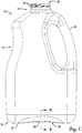
- a bottle 10 is generally illustrated as comprising a neck 12, a body 14, and a base 16 integrally formed with body 14.
- neck 12 can comprise one or more threads or other closure devices 18 located at or near an opening 20 disposed in the upper portion of bottle 10.
- Bottle 10 further comprises a through-handle 22 coupled to at least a portion of body 14
- base 16 of bottle 10 includes a support portion 24 for supporting bottle 10 on a generally flat surface and a push-up portion 26 which is elevated slightly from support portion 24.
- base 16 of bottle 10 includes at least one base parting seam 28 resulting from the formation of bottle 10 in an extrusion blow molding apparatus (not shown in FIG. 1 ). Additional details regarding various embodiments of EBM processes and systems will be discussed in detail shortly.
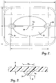
- extrusion blow molded bottle 10 can include at least one support bead 30 extending along base 16 for reinforcing at least a portion of base parting seam 28. As illustrated in FIG. 2 , base parting seam 28 and support bead 30 can extend parallel to length, L, of base 16.
- the term "length" refers to the maximum or longest dimension of an item or component. In one embodiment, the length of base 16 can be at least about 5.08 cm 2 inches). at least about 10.16 cm (4 inches), at least about 15.24 cm (6 inches) and/or not more than about 30.48 cm (12 inches), not more than about 25.4 cm (10 inches), or not more than about 20.32 cm (8 inches).
- the length can be in the range of from about 5.08 to about 30.48 cm (about 2 to about 12 inches), from about 10.16 to about 25.4 cm (about 4 to about 10 inches), or about 15.24 to about 20.32 cm (about 6 to about 8 inches).
- base 16 may also define a second longest dimension, or width, W, as shown in FIG. 2 .
- the width of base 16 can be at least about 5.08 cm 2 inches), at least about 7.62 cm 3 inches), at least about 10.16 cm (4 inches) and/or not more than about 20.32 cm (8 inches), or not more than about 15.24 cm (6 inches).
- the width can be in the range of from about 5.08 to about 25.4 cm (about 2 to about 10 inches), from about 7.62 to about 20.32 cm (about 3 to about 8 inches), or from about 10.16 to about 15.24 cm (about 4 to about 6 inches).
- the ratio of the length (I) of support bead 30 to the length (L) of base 16 can be at least about 0.25:1, at least about 0.35:1, at least about 0.50:1 and/or not more than about 1:5, not more than about 1.2:1, not more than about 1:1, not more than about 0.95:1, not more than about 0.90 not more than about 0.85:1, not more than about 0.80:1, or not more than about 0.75:1. In another embodiment, this ratio can be in the range of from about 0.25:1 to 1.5:1, about 0.35:1 to about 1.2:1, or about 0.50:1 to about 0.95:1. In some embodiments when the ratio of the length of the support bead to the length of the base is greater than 1:1, the support bead may extend upwardly along at least a portion of one of the sidewalls of bottle 10.
- Support bead 30 can have a height (H s) and a width (W s) as shown in FIG. 3 .
- the height of support bead 30 can be at least about 0.0127 cm (0.005 inches), at least about 0.0254 cm (0.01 inches), at least about 0.051 cm (0.02 inches) and/or not more than about 0.254 cm (0.10 inches), not more than about 0.19 cm (0.075) inches), or not more than about 0.127 cm (0.050 inches).
- the height of support bead 30 can be in the range of from about 0.0127 to about 0.254 cm (about 0.005 to about 0.10 inches), about 0.0254 to about 0.19 cm (about 0.010 to about 0.075 inches), or about 0.05 to about 0.127 cm (about 0.02 to about 0.05 inches).
- the ratio of the height of support bead 30 to its width (H s :W s ) is at least about 0.05:1, at least about 0.010:1, at least about 0.20:1 and/or not more than 2:1, not more than about 1:1, not more than about 0.75:1, or not more than about 0.50:1, or in the range of from about 0.05:1 to about 2:1, about 0.010:1 to about 1:1, about 0.20:1 to abut 0.75:1.
- support bead 30 may have a relatively flat profile and may have a height similar to the thickness of bottle 10.
- the ratio of the average thickness (x) of base 16 adjacent support bead 30 to the height (H s ) of support bead 30 can be at least about 0.5:1, at least about 0.75:1, at least bout 1.01:1, at least about 1.1:1, at least about 1.15:1 and/or not more than about 5:1, not more than about 3:1, or not more than about 2:1, or in the range of from about 0.5:1 to about 5:1, about 1.1:1 to about 3:1, or about 1.15:1 to 2:1.
- the average thickness (x) of base 16 may be at least about 0.0254 cm (0.01 inches), at least about 0.05 cm (0.02 inches), at least about 0.076 cm (0.03 inches) and/or not more than about 0.19 cm 0.075 inches), not more than about 0.165 cm (0.065 inches), or not more than about 0.127 cm (0.050 inches), as measured at ten equally spaced locations adjacent support bead 30, wherein five of the measurement locations are on one side of support bead 30 and five of the measurement locations are on the other side of support bead 30.
- the average thickness of base 16 can be in the range of from about 0,025 to about 0,190 cm (about 0.01 to about 0.075 inches), about 0,076 to about 0,165 cm (about 0.03 to about 0.065 inches), or about 0,0762 to about 0,1270 cm (about 0.030 to about 0.050 inches).
- Support bead 30 may be a solid bead that defines a lateral bead cross section 31, as shown in FIG.3 .
- lateral bead cross section 31 may have an area equal to the height of support bead 30 multiplied by its width. In other embodiments, the area of lateral bead cross section 31 may be less than the height of support bead 30 multiplied by its width.
- the area of lateral bead cross section 31 would be less than (0.05) x (0.20) or less than 0.01 square cm (cm 2 ) [(0.02) x (0.08) or less than 0.0016 square inches (in 2 )].
- the area of lateral bead cross section 31 may be not more than 95 percent, not more than about 90 percent, not more than 85 percent, not more than 80 percent, not more than 75 percent, or not more than 50 percent of this value.
- support bead 30 can have a number of suitable shapes.
- lateral bead cross section 31 has a triangular or rectangular shape.
- lateral bead cross section 31 can have a half-polygonal shape, such that support bead 30 has the shape of one half of an nth sided polygon, wherein n is an integer between 5 and 12, inclusive.
- at least a portion of lateral bead cross section 31 can be curved.
- the radius (R) of the curved portion may be at least about 0.013 cm (0.005 inches), at least about 0.025 cm (0.01 inches), at least about 0.05 cm (0.02 inches) and/or not more than about 0.254 cm (0.10 inches), not more than about 0.19 cm 0.075 inches), or hot more than about 0.127 cm (0.050 inches).
- the radius can be the same as the height of support bead 30, while in other embodiments, the radius can be different than the height of support bead 30. Additional shapes for support bead 30 are contemplated and will be discussed in further detail shortly.
- Drop impact performance may be measured in at least one of two ways. The first is the Bruceton staircase method in which the average drop failure height is determined. This method is similar to ASTM D2463 and is described in detail in Example 3. The second method of testing drop impact performance is a static drop impact test carried out at drop heights of 3, 4, and 5 feet. This procedure, described in detail in Example 4, measures the percent of bottles tested that pass (i.e., do not break or crack) when dropped from a certain height.
- bottle 10 may have an average drop height, as measured with the Bruceton method, of at least about 1.07 m 3.5 feet), at least about 1.37 m (4.5 feet), at least about 1.52 m 5 feet) and/or not more than about 3.05 m (10 feet), not more than about 2.44 m (8 feet), or not more than about 2.13 m (7 feet), or in the range of from about 1.07 to about 3.05 m (about 3.5 to about 10 feet), about 1.37 to about 2.44 m (about 4.5 to about 8 feet), or about 1.52 to about 2.13 m (about 5 to about 7 feet).
- average drop height as measured with the Bruceton method
- bottle 10 can have a 0.91 m (3-foot) drop impact pass rate, measured with the static drop impact test as described in Example 4, of at least about 50 percent, at least about 60 percent, at least about 70 percent, at least about 80 percent, at least about 85 percent, at least about 90 percent, or at least about 95 percent.
- the 1.22 m (4-foot) drop impact pass rate of bottle 10 can be at least about 40 percent, at least about 50 percent, at least about 60 percent, at least about 70 percent, or at least about 75 percent, while the 1.52 m (5-foot) drop impact pass rate of bottle 10 can be at least about 15 percent, at least about 20 percent, at least about 25 percent, at least about 35 percent, or at least about 40 percent, measured as described in Example 4.
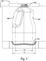
- Mold assembly 110 is configured to produce a container, such as bottle 10, as described in detail above.
- mold assembly 110 comprises two opposing mold halves 112a,b disposed on opposite sides of a parting plane 114, along which at least a portion of mold halves 112a,b contact when mold assembly 110 is in a closed configuration.
- Each of mold halves 112a,b comprises a cavity half 116a,b, which, when mold assembly 110 is in a closed configuration, collectively define a mold cavity having the shape of bottle 10.
- Each half 112a,b of mold assembly 110 presents a neck-forming surface 120a,b, a body forming surface 122a,b, a base-forming surface 124a,b, and a tail-forming surface 130a,b.
- Neck-forming surfaces 122a,b are configured to form the upper portion of bottle 10 and can include one or more thread forming recesses 126 for forming threads or other closure mechanisms at or near the neck of bottle 10.
- Body forming surfaces 122a,b are configured to form the main upright body of bottle 10 and include at least one handle forming surface 128 integral with at least a portion of body forming surface 122, as illustrated in FIG. 5 .
- each of mold halves 112a,b additionally comprise a pinch region 118a,b for cutting or perforating the molten polymer (not shown) during formation of bottle 10.
- pinch regions 118a,b of each of mold halves 1 12a,b present a bead-forming surface 140a,b for creating a support bead, such as support bead 30 discussed above, along the base of bottle 10. Additional details regarding pinch regions 118a,b will now be discussed in detail with particular reference to FIGS. 6a , 6b , and 7 .
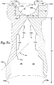
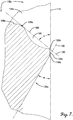
- each mold half 112a,b defines a pinch line 132a,b extending along the junction of base-forming surfaces 124a,b and tail-forming surfaces 130a,b.
- base-forming surface 124a,b presents a pushup-forming surface 134a,b for creating a pushup portion 26 in the base of bottle 10.
- Each of mold halves 112a,b further defines a bead base line 136a,b extending along the junction of pushup-forming surface 134a,b and bead-forming surface 140a,b such that bead-forming surfaces 140a,b extend between bead base lines 136a,b and pinch lines 132a,b of mold halves 112a,b, as shown in FIG. 6a .
- Each bead-forming surface 140a,b has a bead surface height (H B ), illustrated with respect to mold half 112 in FIG. 6a , measured between bead base line 136a and a line 180 drawn perpendicular to parting plane 114 coincident with pinch lines 132a, shown with respect to mold half 112a in FIG. 6a .
- Each bead-forming surface 140 also has a bead surface width (W B ), measured between its pinch line 132b and a line 182 drawn parallel to parting plane 114 coincident with bead base lines 136b, shown with respect to mold half 112b in FIG. 6a .
- the bead surface height and/or bead surface width can be at least about 0.013 cm (0.005 inches), at least about 0.025 cm (0.010 inches), at least about 0.038 cm (0.015 inches) and/or not more than about 0.254 cm (0.10 inches), not more than about 0.191 cm (0.075 inches), or not more than about 0.127 cm (0.050 inches), or in the range of from about 0.013 to about 0.254 cm (about 0.005 to about 0.10 inches), about 0.025 to about 0.19 cm (0.010 to about 0.075 inches), or about 0.038 to about 0.127 cm (about 0.015 to about 0.050 inches).
- the ratio of the bead surface height to the bead surface width can be at least about 0.10:1, at least about 0.25:1, at least about 0.45:1 and/or not more than 2:1, not more than about 1:1, or not more than about 0.75:1, or in the range of from about 0.10:1 to about 2:1, about 0.25:1 to about 1:1, or about 0.45:1 to about 0.75:1.
- Bead-forming surface 140a,b also has a bead surface length, L B , that extends along at least a portion of base-forming surface 124a,b of each of mold halves 112a,b.
- L B bead surface length
- 5 can be at least about 0.25:1, at least about 0.35:1, at least about 0.50:1 and/or not more than about 1:5, not more than about 1.2:1, not more than about 1:1, not more than about 0.95:1, not more than about 0.90 not more than about 0.85:1, not more than about 0.80:1, or not more than about 0.75:1, or in the range of from about 0.25:1 to about 1.5:1, about 0.50:1 to about 1 :1, or about 0.75:1 to about 0.90:1.
- the length of base-forming surface 124 can be at least about 5.08 cm (2 inches), at least about 10.16 cm (4 inches), at least about 15.24 cm (6 inches) and/or not more than about 61 cm (24 inches), not more than about 45.72 cm (18 inches), or not more than about 30.48 cm (12 inches), measured along the longest dimension of base surface 124.
- the length can be in the range of from about 5.08 cm to about 61 cm (about 2 inches to about 24 inches), about 10.16 cm to about 45.72 cm (about 4 inches to about 18 inches), about 15.24 cm to about 30.48 cm about 6 inches to about 12 inches), measured as discussed above.
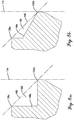
- mold half 112a defines a bead angle reference line 160 extending through the midpoints of bead base line 136a and pinch line 132a and defining a bead extension angle, ⁇ , with parting plane 114.
- bead extension angle ⁇ can be at least about 20°, at least about 30°, at least about 40° and/or not more than about 70°, not more than about 60°, not more than about 50 °, or from about 20° to about 70 °, about 30° to about 60 °, or about 40° to about 50 °.
- conventional extrusion blow molds do not include a bead-forming surface and, consequently, define a bead extension angle of 90°.
- At least a portion of bead-forming surface 140a can be spaced from bead angle reference line 160 to thereby define a bead reference cross section 166 between bead-forming surface 140a and bead angle reference line 160.
- a portion of bead angle reference line 160 can be disposed between bead reference cross section 166 and parting plane 114, as shown in FIG. 7 .
- a portion of bead reference cross section 166 can be disposed between bead angle reference line 160 and parting line 114 (embodiment not shown in FIG. 7 ).
- the area of bead reference cross section 166 can be less than 1/2 times the bead surface height multiplied by its width (1/2 x H B x W B ) and, in some embodiment, may be not more than about 90 percent, not more than 80 percent, not more than 70 percent, or not more than 50 percent of that value.
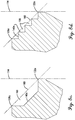
- bead-forming surface 140a may have a bead reference cross section 166 having a variety of different shapes, several examples of which are provided in FIGS. 8a-d .
- bead reference cross section 166 can be a right triangle and, in another embodiment, bead reference cross section 166 may be triangular, but non-right triangular, as shown in FIG. 8b .
- bead reference cross section 166 can include one or more generally straight lines connected by one or more acute (i.e., less than 90°) angles, such as, for example, when bead reference cross section 166 is shaped like one half of a n -sided polygon, wherein n is an integer between 5 and 12, inclusive.
- n is an integer between 5 and 12, inclusive.
- bead reference cross section 166 may have no right angles, while, in other embodiments, bead reference cross section 166 may have at least two right angles, one example of which is illustrated by the stair-stepped cross section 166 depicted in FIG. 8d .
- At least a portion of bead-forming surface 140 can be curved between bead base line 136 and pinch line 132. As depicted in FIGS. 6a , b and 7 , bead-forming surface 140 can be substantially rounded such that bead reference cross section 166 can be generally shaped like a half circle. When at least a portion of bead-forming surface 140 is curved, the radius of the curved portion, illustrated generally as R in FIG.
- the radius can be the same as the height of bead forming surface 140, while in other embodiments, the radius can be different than the height of bead forming surface 140.
- each of tail forming surfaces 130a,b present a pinch surface 142a,b for clamping and sealing the molten polymer during processing and a flashing surface 144a,b located adjacent each of pinch surfaces 142a,b.
- Each of mold halves 112a,b further defines a lower pinch line 146a,b extending along the junction of pinch surfaces 140a,b and flashing surfaces 142a,b such that each of pinch surfaces 140a,b extends between pinch lines 132a,b and lower pinch lines 146a,b.
- pinch surfaces 140a,b can be oriented substantially parallel to parting line 1 14, and, in one embodiment, each of pinch surfaces 140a,b can have an overall length, measured between pinch lines 132a,b and lower pinch lines 146a,b of not more than about not more than about 0.064 cm (0.025 inches), not more than about 0.051 cm (0.020 inches), not more than about 0.038 cm (0.015 inches), not more than about 0.030 cm (0.012 inches), not more than about 0.025 cm (0.010 inches), or not more than about 0.020 cm (0.008 inches).
- a pinch point gap 150 can be defined between opposing pinch regions 118a,b of mold halves 112a,b when mold assembly 110 is in a closed configuration.
- pinch point gap 150 can be at least about 0.002 cm (0.001 inches), at least about 0.005 cm (0.0020 inches), at least about 0.006 cm 80.0025 inches) and/or not more than about 0.191 cm (0.075 inches), not more than about 0.127 cm (0.050 inches), or not more than about 0.089 cm (0.035 inches), measured as the shortest linear distance between opposing pinch lines 132a,b or lower pinch lines 146a,b.
- the pinch point gap can be in the range of from about 0.003 to about 0.191 cm (about 0.001 to about 0.075 inches), about 0.005 to about 0.127 cm (0.002 to about 0.050 inches), or about 0.006 to about 0,089 cm (about 0.0025 to about 0.035 inches).
- flash pocket 148 has a length, L F , of at least about 0.25 inches, at least about 1 inches, at least about 2 inch and/or not more than about 10 inches, not more than about 7 inches, or not more than about 5 inches, measured from lower pinch line 146a,b to the lower edge 158 of the mold half 1 12.
- the flash pocket length can be in the range of from about 0.635 to about 25.4 cm (about 0.25 to about 10 inches), about 2.54 to about 17.78 cm (about 1 to about 7 inches), or about 5.08 to about 12.7 cm about 2 to about 5 inches), measured as described above.
- Flash pocket 148 can be configured in a variety of ways.
- flashing surfaces 144a,b can define one or more flashing angles, such as an upper flashing angle ( ⁇ ), defined between an upper reference line 152 drawn through lower pinch point 146a to intersect parting plane 114, as shown in FIG. 7 , and lower flashing angle ( ⁇ ), defined between a lower reference line 154 drawn through a flashing point 147a and intersecting parting plane 114, as shown in FIG. 6 .
- upper and/or lower flashing angles ⁇ and ⁇ can at least 15°, at least 20°, at least 25° and/or not more than about 60°, not more than about 50°, or not more than about 45°.
- upper and lower flashing angles ⁇ and ⁇ may be the same, while, in another embodiment, flashing angles ⁇ and ⁇ may be different from one another.
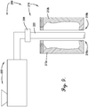
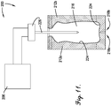
- an extrusion blow molding (EBM) system 200 suitable for forming a blow molded container, such as bottle 10, is illustrated as generally comprising an extruder 202 and a mold assembly 210.
- Extruder 202 is coupled to a die 208 for extruding the molten resin into a parison 220, as shown in FIG. 9 .
- Mold assembly 210 comprises two mold halves 212a,b, which are shiftable between an open configuration wherein mold halves 212a,b are spaced apart from one another, as illustrated in FIG. 9 , and a closed configuration wherein at least a portion of mold halves 212a,b contact one another along a parting plane 214, as shown in FIG. 10a .
- mold halves 212a,b When in the closed configuration, mold halves 212a,b collectively define a mold cavity 216, which generally has the shape of the final container. Mold halves 212a,b can be configured in any suitable configuration and, in one embodiment, can include one or more of the features discussed in detail previously with respect to FIGS. 4-8 .
- EBM system 200 can be configured to operate using any type of blow molding process.
- EBM system 200 can be a "shuttle” or “intermittent” process, configured to produce a "hanging" parison, as generally depicted in FIGS. 9-11 .
- mold assembly 210 can be situated on a moving platform (not shown) for transporting the assembly up to die 208 and for closing mold halves 212a,b around parison 220. Thereafter, mold assembly 210 can move away from die 208 to inflate, cool, and eject the finished container from the assembly. Due to the mechanics of this type of process, polymer can be continuously extruded through die 208 at a relatively slow rate.
- mold assembly 210 can be in a fixed location below the opening of die 208 and the full "shot weight" of polymer (i.e., the weight of the final container plus its flash) can be rapidly pushed through die 208 directly after the preceding container is ejected from mold assembly 210, but before the current container is inflated.
- Intermittent processes can either utilize reciprocating screw action to push the parison out of mold assembly 210, or the extrudate can be continuously extruded into a cavity which utilizes a plunger to push the parison (embodiment not shown).
- EBM system 200 can also be configured to operate using a wheel process (embodiment not shown).
- a wheel process polymer is continuously extruded from the die at a relatively high speed.
- a 1.22 m (4-ft) to 6.09 m (20-ft) diameter wheel moving at about 1 to about 10 revolutions per minute grabs each parison as it is extruded from the die and lays the parison into a one of many molds attached to the outer circumference of the wheel. Mold closure, parison inflation, cooling, and ejection of the bottle occurs sequentially as the wheel turns.
- the parison can exit the die in either an upward or downward direction.
- Extruder 202 is not limited and can be any suitable type of extruder.
- extruder 202 can be a high speed extruder capable of delivering polymer flow rates which manifest shear rates at the die exit of at least about 450 s -1 , at least about 550 s -1 , or at least about 600 s -1 .
- extruder 202 can be operated at a shear rate in the range of from 500 to 10,000 s -1 , 600 to 5,000 s -1 , or 700 to 2,000 s -1 .
- the volumetric output rate (Q) is determined by measuring the mass of material extruded over a fixed time interval and dividing by the melt density.
- the polymeric material introduced into extruder 202 can be a polyester or copolyester.
- One copolyester suitable for use in all embodiments of the present invention comprises (a) a dicarboxylic acid component comprising: (i) 90 to 100 mole% of terephthalic acid residues; (ii) 0 to 10 mole% of aromatic and/or aliphatic dicarboxylic acid residues having up to 20 carbon atoms; and (b) a glycol component comprising: (i) 88 to 93 mole% of ethylene glycol residues; and (ii) 7 to 12 mole% residues of at least one difunctional glycol chosen from 1,4-cyclohexanedimethanol, neopentyl glycol, 2,2,4,4-tetramethyl-1,3-cyclobutanediol, isosorbide, or mixtures thereof; (c) at least one branching agent in the amount ranging from 0.1 to 1.0 mole% based on the total mo
- polyester material may be utilized to produce an extrusion blow molded container, at the shear rates listed above, having low sidewall haze value of less than about 15 percent, less than about 10 percent, less than about 7 percent, less than about 5 percent, or less than about 4 percent, as measured on the side wall of the bottle according to ASTM D 1003, Method A using a BYK-Gardner HazeGuard Plus.
- suitable polymers including other polyester polymers, suitable for use in other embodiments of the present invention will be discussed in detail shortly.
- extruder 202 can be operated with a reverse heating profile, such that the temperature at the inlet of extruder 202 is higher than the temperature at the outlet of die 208.
- the temperature at the outlet of die 208 can be at least about 190°C, at least about 210°C, at least about 220 °C and/or not more than about 285 °C, not more than about 275°C, or not more than about 265°C.
- the temperature at the outlet of die 208 can be in the range of from about 190°C to about 285°C, about 210°C to about 275°C, or about 220°C to about 265°C.
- the temperature of the molten polymer exiting the outlet of die 208 measured directly on the polymer just before blowing, can be at least about 180°C, at least about 200 °C, at least about 210°C and/or not more than about 280°C, not more than about 270°C, and/or not more than about 260°C, or in the range of from 180°C to about 280°C, about 200°C to about 270°C, or about 210°C to about 260°C.
- pinch point gap 250 can be formed between opposing pinch surfaces 224a,b, as shown in FIG. 10b .
- pinch point gap 250 can be at least about 0.003 cm (0.001 inches), at least about 0.004 cm (0.0015 inches), at least about 0.005 cm 0.002 inches) and/or not more than about 0.191 cm (0.075 inches), not more than about 0.127 (0.05), or not more than about 0.089 cm (0.035 inches), measured as the shortest linear distance between pinch surfaces 224a,b.
- the pinch point gap can be in the range of from about 0.003 to about 0.191 cm (about 0.001 to about 0.075 inches), about 0.004 to about 0.127 cm (about 0.0015 inches to about 0.05 inches), or about 0.005 to about 0.089 cm (about 0.002 to about 0.035 inches).
- mold halves 212a,b Once mold halves 212a,b have fully closed, air or other pressurized fluid can be injected into sealed parison 222 with an inflation device 226, as shown in FIG. 11 .
- the resulting blow molded container can then be allowed to cool for at least about 5 seconds, at least about 8 seconds, or at least about 10 seconds and/or not more than about 45 seconds, not more than about 30 seconds, not more than about 20 seconds, not more than about 16 seconds, or not more than about 14 seconds via contact with mold halves 212a,b, which are maintained at a temperature at least about 15°C, at least about 18°C, at least about 20 °C and/or not more than about 50 °C, not more than about 40 °C, or not more than 30 °C.
- the mold cycle time can also be in the range of from about 5 to about 45 seconds, about 8 to about 30 seconds, about 10 to about 20 seconds, while the mold temperature can be maintained in the range of from about 15 °C to about 50 °C, about 18 °C to about 40 °C, or about 20 °C to about 30 °C.
- the initial blow molded container can be removed from mold assembly 210 and transported to a downstream deflashing zone, wherein at least a portion of the tail flash can be removed.
- at least a portion of the transportation from mold assembly 210 to the deflashing zone can be carried out by gripping, either manually or with a robotic device, the tail flash of the initial blow molded container.
- Bottle 310 comprises a neck 312, a body 314, a base 316, and tail flash 342 extending along at least a portion of base 316.
- tail flash 342 comprises a support portion (or support bead) 344 coupled to base 316 of bottle 310 and an elongated portion 346 extending outwardly from support bead 344.
- elongated portion 346 is configured for removal from support portion 344 when bottle 310 is deflashed.
- Support portion 344 can remain intact and, once elongated portion 346 of tail flash 342 has been removed, can have similar properties (including height, width, and height-to-width ratio) as support bead 30 of bottle 10, discussed in detail previously.
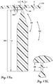
- FIGS. 13a and 13b provide enlarged views of tail flash 342, including support portion (or bead) 344 and elongated portion 346.
- elongated portion 346 of tail flash 342 can further comprise an upper pinch portion 348 and a lower flashing portion 350 respectively formed by the pinch point gap and flashing pocket of an EBM mold assembly (not shown) configured as discussed previously.
- 13b can be at least about 0.013 cm (0.001 inches), at least about 0.013 cm (0.005 inches), or at least 0.025 cm (0.01 inches) and/or not more than 0.191 cm (0.075 inches), not more than about 0.127 cm (0.050 inches), or not more than about 0.089 cm (0.035 inches), or in the range of from about 0.013 to about 0.191 cm (about 0.005 to about 0.075 inches), about 0.013 to about 0.127 cm (about 0.005 to about 0.050 inches), or about 0.025 to about 0.089 cm about 0.01 to about 0.035 inchesl. As shown in FIG.
- the length of flashing portion 350 can be at least about 0.635 cm (0.25 inches), at least about 2.54 cm 1 inch), at least about 5.08 cm 2 inches), or at least about 7.62 cm 3 inch) and/or not more than about 25.4 cm 10 inches), not more than about 17.8 cm (7 inches), or not more than about 12.7 cm (5 inches), or in the range of from about 0.635 to about 25.4 cm (about 0.25 to about 10 inches), about 2.54 to about 17.8 cm (about 1 to about 7 inches), about 5.08 to about 12.7 cm (about 2 to about 5 inches).
- support portion 344 can have any suitable shape, including, for example, those previously discussed with respect to support bead 30.
- the cross sectional area of support portion 344 of tail flash 342 can be equal to the height of support portion 344 times its width.
- the cross sectional area of support portion 344 can be less than this values.
- the cross sectional area of support portion can be no more than about 90 percent, no more than about 80 percent, or no more than about 70 percent of the height of support portion 344 times its width.
- the radius may have radius of at least about 0.013 cm (0.005 inches), at least about 0.025 cm (0.01 inches), at least about 0.051 cm (0.02 inches) and/or not more than about 0.254 m (0.10 inches), not more than about 0.191 cm (0.075 inches), or not more than about 0.127 cm (0.050 inches), or from about 0.013 to about 0.254 cm (about 0.005 to about 0.10 inches), about 0.025 to about 0.191 cm (0.01 to about 0.075 inches), or about 0.051 to about 0.127 cm (about 0.02 to about 0.05 inches).
- the radius can be the same as the height of bead support portion 344, while in other embodiments, the radius can be different than the height of bead support portion 344.
- At least a portion of elongated portion 346 of tail flash 342 can be mechanically removed from bottle 31 0 using, for example, a side knock machine or other known device.
- at least about 80 percent, at least about 90 percent, at least about 95 percent, at least about 97 percent, or at least about 99 percent of the total length of elongated portion 346 can be removed from bottle 310, thereby leaving support portion (bead) 344 coupled to base 316 of bottle 310.
- support portion (bead) 344 can disengage or breaks away from support bead (or portion) 344 along at least a portion of the dimension Y of pinch portion 348.
- Bottles and other containers produced according to various embodiments of the present invention can be easier to trim (deflash) than similar bottles produced with conventional processes and systems.
- the torque required to remove elongated portion 346 from support bead (or portion) 344 of bottle 310 can be at least about 15 percent, at least about 25 percent, at least about 35 percent, at least about 50 percent and/or not more than 100 percent, not more than about 90 percent, not more than about 80 percent, not more than about 75 percent less than the torque required to trim (or deflash) an analogous bottle that does not include a support bead, using the torque-to-deflash method described in detail in Example 2.
- the phrase "analogous bottle that does not include a support bead” refers to a bottle produced in exactly the same manner as bottle 310 with the exception being that the analogous bottle does not include a support bead 344.
- mold assemblies used to produce the analogous bottle would not include a bead forming surface as described in detail previously with respect to FIGS. 4-8 above.
- the torque to deflash can be in the range of about 15 to 100 percent less, about 25 to about 90 percent less, or about 35 to about 80 percent less than the torque required to deflash an analogous bottle that does not include a support bead.
- the absolute value of the torque required to deflash bottle 310 can be dependent on, inter alia, the size of the bottle. Regardless of bottle size, however, bottles and other containers produced according to embodiments of the present invention can exhibit a lower specific torque to deflash than conventionally produced bottles of similar size and shape.
- specific torque to deflash refers to the amount of torque required to trim or deflash a bottle or container normalized (divided) by the total weight (in US ounces or oz.) of the deflashed bottle or container.
- bottle 310 can have a specific torque to deflash of not more than about 0.079 J/g (20 in-lb f /oz), not more than about 0.072 J/g (18 in-lb f /oz), not more than about 0.06 J/q (15 in-lb f /oz), not more than about 0.048 J/g (12 in-lb f /oz), not more than about 0.04 J/q (10 in-lb f /oz), or not more than about 0.032 J/g (8 in-lb f /oz).
- Specific methods for measuring torque to deflash and specific torque to deflash will be described shortly in Example 2.
- bottles and other containers produced according to embodiments of the present invention may require far less effort to deflash than traditional blow molded containers.
- the absolute value of the torque required to deflash bottles of the present invention may depend on several factors, including, for example, bottle size, material, and design.
- the bottle may be of similar construction to the bottle shown in FIG.
- Bottles and other containers produced according to embodiments of the present invention can be made of any suitable material, including, but not limited to, copolyesters, polyvinyl chloride (PVC), polyethylene, and polypropylene.
- containers as described herein can be made from a polyolefin-based material having a flexure modulus (or stiffness), measured according to ASTM D-790, of less than about 1500 MPa.
- the bottles may be made from a non-polyolefin material and may even be made from a polymeric material having a substantially higher modulus.
- bottles and containers of the present invention can be from a material having a flexure modulus of at least about 1550 MPa, at least about 1650 MPa, at least about 1750 MPa, at least about 1850 MPa and/or not more than about 3000 MPa, not more than about 2850 MPa, or not more than about 2650 MPa, or in the range of from about 1550 to about 3000 MPa, about 1650 to about 2850 MPa, or about 1750 to about 2650 MPa.
- the polymeric material used to produce bottles and other containers as described herein can be a polyester material.
- suitable polyester materials are described in co-pending U.S. Patent Application Serial No. 13/092,978 filed on July 28, 2011 .
- the term "polyester,” refers to a synthetic polymer prepared by the reaction of one or more difunctional carboxylic acids and/or multifunctional carboxylic acids with one or more difunctional hydroxyl compounds and/or multifunctional hydroxyl compounds and is intended to encompass both homopolyesters and copolyesters.
- Polyester materials suitable for use herein can include a dicarboxylic acid component and a diol component, each including one or more residues.
- the dicarboxylic acid component of the polyester material used herein may include at least about 85 mole percent, at least about 90 mole percent, at least about 95 mole percent, at least about 97 mole percent, or at least about 99 mole percent of residues of terephthalic acid or an ester thereof ( i.e., dimethyl terephthalate), with the balance being one or more modifying residues listed below.
- the dicarboxylic acid component may comprise 100 percent of residues of terephthalic acid or dimethyl terephthalate.
- such a residue may be selected from the group consisting of isophthalic acid, 4,4'-biphenyldicarboxylic acid, 1,4-, 1,5-, 2,6-, 2,7-naphthalenedicarboxylic acid, and trans-4,4'-stilbenedicarboxylic acid, and esters thereof.
- copolyesters suitable for use in all embodiments of the present invention comprise (i) a diacid residue of which at least 80 mole percent is a diacid residue component selected from terephthalic acid, naphthalenedicarboxylic acid, 1,4-cyclohexanedicarboxylic acid, isophthalic acid or mixtures thereof, and (ii) a diol residue of which at least 80 mole percent is a diol residue component selected from one or more diols containing 2 to about 10 carbon atoms, wherein the diacid residue component is based on 100 mole percent total diacid residues and the diol residue component is based on 100 mole percent total diol residues.
- copolyesters suitable for use in all embodiments of the present invention comprise (i) a diacid residue of which at least 80 mole percent is a diacid residue component selected from terephthalic acid, naphthalenedicarboxylic acid, 1,4-cyclohexanedicarboxylic acid, isophthalic acid or mixtures thereof, and (ii) a diol residue of which about 50 mole percent of ethylene glycol residues and 50 mole percent 1,4-cyclohexane dimethanol residues, wherein the diacid residue component is based on 100 mole percent total diacid residues and the diol residue component is based on 100 mole percent total diol residues.
- copolyesters suitable for use in all embodiments of the present invention comprise (i) a diacid residue of which at least 80 mole percent is a diacid residue component selected from terephthalic acid, naphthalenedicarboxylic acid, 1,4-cyclohexanedicarboxylic acid, isophthalic acid or mixtures thereof, and (ii) a diol residue of which about 50 to 100 mole percent is ethylene glycol residues and 0 to 50 mole percent of residues selected from one or more diols containing 2 to about 10 carbon atoms, wherein the diacid residue component is based on 100 mole percent total diacid residues and the diol residue component is based on 100 mole percent total diol residues.
- copolyesters suitable for use in all embodiments of the present invention comprise (a) a dicarboxylic acid component comprising: (i) 85 to 95 mole% of terephthalic acid residues; (ii) 5 to 15 mole% of isophthalic acid residues; and (b) a glycol component comprising: (i) 90 to 100 mole% of ethylene glycol residues; and (ii) 0 to 10 mole% residues of at least one difunctional glycol chosen from 1,4-cyclohexanedimethanol, neopentyl glycol, 2,2,4,4-tetramethyl-1,3-cyclobutanediol, isosorbide, or mixtures thereof; (c) at least one branching agent in the amount ranging from 0.1 to 1.0 mole% based on the total moles of glycol residues if said branching agent has hydroxyl substituents and otherwise based on the total moles of acid residues; wherein the total mole% of the acid residues is
- copolyesters suitable for use in all embodiments of the present invention comprise (a) a dicarboxylic acid component comprising: (i) 85 to 95 mole% of terephthalic acid residues; (ii) 5 to 15 mole% of isophthalic acid residues; and (b) a glycol component comprising: (i) 90 to 100 mole% of ethylene glycol residues; and (ii) 0 to 10 mole% residues of a diol residue component selected from one or more diols containing 2 to about 10 carbon atoms; (c) at least one branching agent in the amount ranging from 0.1 to 1.0 mole% based on the total moles of glycol residues if said branching agent has hydroxyl substituents and otherwise based on the total moles of acid residues; wherein the total mole% of the acid residues is 100 mole%, and the total mole% of the glycol residues is 100 mole%.
- a dicarboxylic acid component comprising: (
- the diol component of the polyester selected for extrusion blow molding of containers as described herein can include at least about 50 mole percent, at least about 65 mole percent, at least about 80 mole percent, at least about 85 mole percent, at least about 88 mole percent, at least about 90 mole percent, or 100 percent of residues of ethylene glycol with one or more modifying difunctional glycols selected form the group consisting of from 1,4-cyclohexanedimethanol, neopentyl glycol, 2,2,4,4-tetramethyl-1,3-cyclobutanediol, isosorbide (CAS registration number 652-67-5), diethylene glycol, 1,2-propanediol, 1,5-pentanediol, 1,6-hexanediol, p-xylene glycol, 1,3-propanediol, 1,4-butanediol, and mixtures thereof.
- the selected polyester may also include at least about 0.05 mole percent, at least about 0.10 mole percent, at least about 0.20 mole percent, at least about 0.30 mole percent, or at least about 0.50 mole percent of one or more branching agents selected from the group consisting of trimellitic acid, trimellitic anhydride, trimethylolpropane, pentaerythritol, and trimethylolethane.
- branching agents selected from the group consisting of trimellitic acid, trimellitic anhydride, trimethylolpropane, pentaerythritol, and trimethylolethane.
- the polyester material selected to produce blow molded articles as described herein can have an inherent viscosity (IhV) of at least 0.65 dUg, at least about 0.70 dL/g, at least about 0.72 dL/g, at least about 0.74 dL/g, at least about 0.76 dL/g, at least about 0.78 dL/g and/or not more than about 1.10 dL/g, not more than about 1.00 dL/g, not more than about 0.95 dL/g, not more than about 0.90 dUg, or not more than 0.85 dL/g, measured in a 60/40 (wt/wt) phenol/tetrachloroethane at a concentration of 0.25 g/50 mL at 25°C.
- IhV inherent viscosity
- the IhV can be at in the range of from about 0.65 to about 1.10 dL/g, about 0.70 dUg to about 1.0 dL/g, about 0.72 dL/g to about 0.90 dL/g, or about 0.76 dUg to about 0.85 dL/g.
- Polyesters suitable for use with the present invention can preferably be compatible with the overall PET recycle stream.
- the phrase "compatible with the overall PET recycle stream” refers to a polyester composition that passes the DSC melting temperature requirement of the Association of Post Consumer Plastic Recycler's published test method. As actual recycle streams of PET may have variability, testing for compatibility with the overall PET recycle stream is done using a virgin PET Recycle Standard resin.
- the PET Recycle Standard resin is defined herein as a PET resin comprising 96 to 99.5 mole percent terephthalic acid residues and 0.5 to 4.0 mole percent isophthalic acid residues and 100 mole percent ethylene glycol residues based upon 100 mole percent acid residues and 100 mole percent glycol residues (as PET polyesters may contain a small amount of diethylene glycol produced in situ or added to maintain a constant minimal amount of diethylene glycol, the diethylene glycol is counted as part of the 100 mole percent of ethylene glycol).
- CCD PET Critical Guidance Document
- the PET Recycle Standard resin defined above includes, but is not limited to, the named PET Control Resins listed in the CGD and reproduced in Table 1, below.
- Table 1 PET Control Resins listed in CGD for Testing Compatibility Named PET Control Resins for Low IV, water bottle applications Named PET Control Resins for CSD and non-water bottle applications Eastman aqua PET RH314 Eastman PET CB12 Invista Polyclear Splash, 3301 Invista Polyclear Refresh, 1101 M&G Cleartuf Turbo II M&G Cleartuf MAX Wellman HP 807 Wellman HP 806 DAK Lasar+W L44A DAK Laser+ B95A
- the CGD includes a procedure for preparing blend samples of a resin to be tested and one of several named PET Control resins.
- the Recycle Sample Prep Protocol is based upon, but not limited to, the CGD procedure.
- the Recycle Sample Prep Protocol is the procedure by which a polyester and a Standard PET Recycle resin are combined and processed before measuring the melting point temperature.
- the Recycle Sample Prep Protocol is defined as the following method: The test polyester and a control PET resin are independently dried, extruded, re-pelletized, and crystallized. Extrusion processing is conducted according to typical PET processing conditions (240-280°C barrel temperature settings). Crystallization is conducted at approximately 160°C.
- a pellet-pellet blend is formed by combining the re-pelletized test polyester and the re-pelletized control PET resin from the first step.
- the blend is dried at 160°C for at least 4 hours.
- the dry blend from Step 2 is extruded, re-pelletized, and crystallized.
- Extrusion processing is conducted according to typical PET processing conditions (240 to 280°C barrel temperature settings). Crystallization is conducted at approximately 160°C.
- the crystallized blend from the previous step is solid-stated at a temperature between 195 and 215°C until a nominal 0.80 dL/g intrinsic viscosity (ItV) is obtained as measured by ASTM D 4603.
- a DSC melting point temperature measurement is conducted on the solid-stated blend the previous step at 10 °C/min, on the second heat scan following annealing for 2 minutes at 280°C.
- control PET resin is one of the named PET Control Resins listed in the CGD and blended with an innovative resin (test polyester) at a level of 0 weight percent, 25 weight percent, or 50 weight percent of the innovative resin
- T m melting point temperature
- the control PET resin can be the PET Recycle Standard resin as defined herein above, and the test polyesters can be polyesters useful in embodiments of the present invention.
- the melting point temperature, T m of a blend comprising 50 weight percent of polyesters useful for the invention with 50 weight percent of a PET Recycle Standard resin and prepared according to the above Recycle Sample Prep Protocol of at least about 200°C, at least about 210°C, at least about 220°C, at least about 230°C, at least about 235°C and/or not more than about 270°C, not more than about 260 °C, not more than about 255°C, not more than about 250 °C, not more than about 245°C, not more than about 240°C, or not more than about 230 °C, or in the range of from about 200°C to about 270°C, about 210°C to about 260°C, about 220°C to about 255°C, about 230°C to about 250°C or about 235°C to about 245°C.
- the polymeric material can be selected to form a transparent bottle or container having a sidewall haze value of less than about 15 percent, less than about 10 percent, less than about 7 percent, less than about 5 percent, or less than about 4 percent, as measured on the side wall of the bottle according to ASTM D 1,003, Method A using a BYK-Gardner HazeGuard Plus.
- Bottles and containers produced as described herein can be formed from two or more separate layers of polymeric material (e.g., be multi-layer containers) or can be prepared from one layer of polymer (e.g., a single layer container), as generally described herein.
- Bottles and containers produced according to embodiments of the present invention can be of any suitable shape, size, and volume.
- the blow molded containers produced herein can have a total internal volume of at least about 0.177 l [6 fluid ounces (fl. oz.)], at least about 0.237 ml (8 fl. oz.), at least about 0.473 l (16 fl. oz.), at least about 0.946 ml (32 fl. oz), or at least about 1.183 l (40 fl. oz.), at least about 1.774 l (60 fl. oz.), at least about 2.366 l (80 fl.
- the volume of the bottles or containers described herein can be in the range of from about 0.177 to about 8.871 l (about 6 to about 300 fl. oz), about 0.946 to about 7.570 l (about 32 to about 256 fl.
- bottles or containers produced herein can have a final (deflashed) weight of at least about 50 grams, at least about 75 grams, at least about 100 grams and/or not more than about 450 grams, not more than about 300 grams, not more than about 200 grams, or not more than about 150 grams, or in the range of from about 50 to about 450 grams, about 75 to about 300 grams, or about 1 00 to about 250 grams.
- Example 1 Preparation of Various Bottles from a Polyester Material
- the inventive mold assembly, E1 included a curvilinear bead-forming surface having height of 0.051 cm (0.02 inches) and a width of 0.08 cm (0.03 inches). The length of the pinch surface was 0.02 cm (0.008 inches). While the pinch surface length of the comparative mold assembly, C1, was the same as the pinch surface length for mold assembly E1, mold assembly C1 did not include a bead-forming surface, as shown in FIG. 15a .
- Pellets of a polyester polymer having a dicarboxylic acid component that included 99.7 mole percent terephthalic acid and 0.3 mole percent trimetallic anhydride (TMA) and a diol component including 90.5 mole percent ethylene glycol and 9.5 mole percent 1,4-cyclohexanedimethanol were dried for 12 hours at a temperature of 65 °C.
- IhV inherent viscosity
- the die bushing and mandrel pin tooling were sized at 70 mm and 68 mm (outer diameter), respectively.
- the extruder screw rotated at between 12 and 14 revolutions per minute and the temperature of the 5-zone barrel and die head were controlled between 230 °C and 260 °C.
- the molten polyester was extruded from the die and the resulting parison was closed into one of the two mold assemblies described above.
- the mold cushion was controlled to a setting of 7, but the distance between the two mold halves was varied by placing shim inserts on each side of the mold at a vertical location close to the mold base.
- the width of the pinch portion of the tail flash was also modified (width 'Y" showing by 348 in Figure 13 b) .
- Multiple bottles were produced for each of several mold spacings between 0.036 cm (0.014 inches) and 0.076 cm (0.030 inches) using both comparative mold assembly C1 and inventive mold assembly E1.
- mold cycle times for each type of bottle were also varied between 13 and 14.5 seconds.
- a summary of the mold type, mold spacing, and cycle time for each type of bottle produced is provided in Table 3, below.
- bottles produced with inventive mold assembly E1 include a support bead located proximate the base of the container.
- the height and width of the support bead for several types of inventive bottles were measured via microscopy.
- the distance between pinch surfaces ⁇ e.g., the "pinch off distance" of the bottles varied as well.
- Table 2, below also provides the "pinch off distance” for several types of inventive and comparative bottles were measured via microscopy.
- the ratios of bead height to bead width for several inventive samples were also calculated.
- Table 2 Summary of Pinch Region Dimensions for Several Bottles Mold Assembly Mold Spacing [ cm ] (in) Mold Cycle Time (s) Pinch-off Distance [ cm ] (in) Bead Hight [ cm ] (in) Bead Width [ cm ] (in) H:W Ratio C1 0.051 (0.020) 13 0.180 (0.0071) - - - C1 0.071 (0.028) 13 0.021 (0.0084) - - - C1 0.076 (0.030) 13 0.025 (0.0098) - - - E1 0.036 (0.014) 13 0.016 (0.0062) 0.046 (0.018) 0.170 (0.067) 0.686 (0.27) E1 0.051 (0.020) 13 0.178 (0.0070) 0.046 (0.018) 0.191 (0.075) 0.61 (0.24) E1 0.056 0.022 13 0.201 (0.0079) 0.061 (0.024) 0.201 (0.079)
- Table 3 Summary of Extrusion Blow Molded Bottles Produced and Tested in Examples 1-4 Mold Assembly Mold Spacing [cm] (in) Mold Cycle Time [s] Air Cool Time [s] Torque to Deflash [J] (in-lb f ) Static Drop Impact Pass Rate Bruceton Staircase Drop % Pass at 0.92 m (3 ft.) % Pass at 1.22 m (4 ft.) % Pass at 1.52 m (5 ft.) Average Drop Height [m] (ft.) C1 0.046 (0.018) 13 0 6.03 (49) 45 20 10 0.77 ⁇ 0.25 (2.5 ⁇ 0.8) C1 0.051 (0.020) 13 10 6.15 (50) 55 30 10 1.20 ⁇ 0.25 (3.9 ⁇ 0.8) C1 0.056 (0.022) 13 10 7.75 (63) 75 65 30 1.36 ⁇ 0.52 (4.4 ⁇ 1.7) C1 0.061 (0.024) 13 10 11.07 (90) 90 75 50 1.68 ⁇ 0.36
- the following drop impact test procedure is similar to the one provided in ASTM Method D2463. However, the procedure below was altered to eliminate bias that may result from the orientation of a handled bottle and to utilize a starting height (e.g., 1.22 m [4 ft.]) and height increment (e.g., 0.30 m [1 ft]) more suited for the size and shape of an 2.632 l (89 oz.) test bottle.
- a starting height e.g., 1.22 m [4 ft.]
- height increment e.g. 0.30 m [1 ft]
- the first bottle e.g., bottle 1 of 10
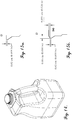
- the first bottle was positioned on a swing-away platform ledge with variable height adjustment, as schematically depicted in FIG. 17 .
- Each of the first ten of the bottles tested were oriented on the platform with the handle facing outwardly (i.e., away from the hinge of the platform as shown in FIG. 17 ) and each of the second set of ten bottles were oriented with the handle facing inwardly (i.e., toward the hinge of the platform).
- the first bottle was dropped from a height of 1.22 m (4 feet). If the bottle did not crack, break, or otherwise split, it passed. If the bottle 1 passed the 1.22 m (4-foot) drop height, the second bottle (e.g., bottle 2 of 10) was dropped at a height of 1.52 m (5 feet). However, if the bottle 1 failed at the 1.22 m (4-foot) drop height, bottle 2 was dropped at a height of 0.91 m (3 feet). Similarly, the passage or failure of bottle 2 at its drop height determined the height at which bottle 3 was dropped - e.g., at a 0.30 m (one-foot) increment above (if bottle 2 passed) or below (if bottle 2 failed) the drop height of bottle 2. The pattern continued in this "staircase" fashion until all 10 bottles had been dropped. The process was repeated with the second set of ten bottles having an inwardly facing handle orientation as described above.
- the average failure height was determined by adding failure heights of each bottle, dividing the result by the total number of failures, and subtracting one half of the test increment ⁇ e.g., 0.5 feet). The resulting values for each type of bottle was determined and the results are listed in listed in Table 3, above.
- bottles produced with mold assembly E1 generally exhibited higher drop impact pass rates and average drop heights than bottles produced with mold assembly C1, for the same mold spacing and cycle time.
- bottles produced with mold assembly C1 tended to exhibit better drop impact performance than those produced with mold assembly E1.
- bottles, both comparative and inventive, produced using wider mold spacings were generally more difficult to trim than bottles produced with narrow mold spacings.
- bottles having a 13-second cycle time also tended to exhibit lower torque to deflash values than those bottles, both comparative and inventive, produced with a 14.5-second cycle time.
- inventive bottles produced using mold assembly E1 tended to require less torque to deflash than bottles produced using mold assembly C1, thereby indicating that the inventive bottles were easier to trim than those produced with the mold C1.
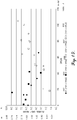
- FIGS. 18 and 19 respectively, correlate the drop impact strength and the average drop height versus the torque to deflash of each of the inventive and comparative bottles tested in Examples 2-4.
- bottles produced with inventive mold assembly E1 possess the desirable combination of increased strength (e.g. high average drop height of greater than 1.83 m (6 feet) and high 0.91 m (3-foot) pass rate greater than 80 percent) and greater ease of trimming (e.g., torque to deflash of less than 6.78 J [60 in-lb f ]).
- increased strength e.g. high average drop height of greater than 1.83 m (6 feet) and high 0.91 m (3-foot) pass rate greater than 80 percent
- greater ease of trimming e.g., torque to deflash of less than 6.78 J [60 in-lb f ]
- bottles prepared with the conventional mold assembly C1 only exhibit suitable drop impact strength (i.e., high drop impact pass rate and/or high average drop height) at high torque levels, such as those above 6.78 J (60 in-lb f ). At lower torque levels, comparative bottles exhibit less-than-acceptable drop impact strength.
- suitable drop impact strength i.e., high drop impact pass rate and/or high average drop height
- bottles produced with inventive mold assembly E1 tended to exhibit greater than 80 percent pass rate at 0.91 m (3 feet), while simultaneously having torque values in the 0 to 2.26 J (0 to 20 in-lb f ) range.
- bottles produced with mold assembly C1 only exhibited greater than 80 percent pass rate at 3 feet, when the flash was hard to remove (torque values in the 6.78-11.3J (60-100 in-lb f ) range).
- bottles produced with the E1 mold show a 66 to 100 percent reduction in torque required to deflash the container, relative to bottles produced with the C1 mold, e.g., analogous bottles that do not include a support bead, at mold setup conditions which give optimal drop performance.
Landscapes
- Engineering & Computer Science (AREA)
- Mechanical Engineering (AREA)
- Manufacturing & Machinery (AREA)
- Ceramic Engineering (AREA)
- Containers Having Bodies Formed In One Piece (AREA)
- Blow-Moulding Or Thermoforming Of Plastics Or The Like (AREA)
- Moulds For Moulding Plastics Or The Like (AREA)
Claims (15)
- Extrusionsblasformbehälter (10, 310) aufweisend:einen Hals (12, 312);einen Körper (14, 314);einen Griff (22), der mit mindestens einem Teil des Körpers (14, 314) gekoppelt ist, wobei der Griff (22) ein Durchgangsgriff ist; undeine Basis (16, 316),wobei die Basis (16, 316) mindestens eine aus der Bildung des Behälters (10, 310) in einer Blasformvorrichtung (200) resultierende Basistrennlinie aufweist,dadurch gekennzeichnet, dass die Basis (16, 316) ferner einen Trennlinienstützwulst (30) zum Verstärken wenigstens eines Teils der Basistrennlinie aufweist, wobei der Stützwulst (30) ein Verhältnis von Höhe zu Breite von mindestens 0,05:1 und nicht mehr als 2:1 aufweist.
- Behälter (10, 310) nach Anspruch 1, wobei der Stützwulst (30) fest ist.
- Behälter (10, 310) nach Anspruch 1, wobei die Querschnittsfläche des Stützwulstes (30) kleiner ist als die Höhe des Stützwulstes (30) multipliziert mit der Breite des Stützwulstes (30).
- Behälter (10, 310) nach Anspruch 1, wobei der Stützwulst (30) einen linearen Seitenquerschnitt (31) aufweist.
- Behälter (10, 310) nach Anspruch 1, wobei die Höhe des Stützwulstes (30) mindestens 0,127 mm (0,005 inch) und nicht mehr als etwa 2,54 mm (0,100 inch) beträgt.
- Behälter (10, 310) nach Anspruch 1, wobei sich der Stützwulst (30) entlang mindestens 90 % der Länge der Basis des Behälters (10, 310) erstreckt.
- Behälter (10, 310) nach Anspruch 1, wobei das Verhältnis der Höhe des Stützwulstes (30) zu der mittleren Dicke der Basis (16, 316) des Behälters (10, 310) benachbart zum Stützwulst (30) mindestens 0,5:1 und nicht mehr als 5:1 beträgt.
- Behälter (10, 310) nach Anspruch 1, wobei der Behälter (10, 310) aus einem Material mit einem Biegemodul von mindestens 1550 MPa gebildet ist.
- Behälter (10, 310) nach Anspruch 8, wobei das Material mindestens einen Polyester umfasst.
- Behälter (10, 310) nach Anspruch 9, wobei das gesamte Innenvolumen des Behälters (10, 310) mindestens etwa 177,6 ml (6 fl. oz) und nicht mehr als 8880 ml (300 fl. oz) beträgt.
- Behälter (10, 310) nach Anspruch 1, wobei der Behälter (10, 310) einen Seitenwand-Trübungswert von weniger als 15 % aufweist.
- Behälter (10, 310) nach Anspruch 1, weiter aufweisend:einen gestützten Bodenbutzen (342), der sich entlang wenigstens eines Teils der Basis (16, 316) erstreckt, wobei der gestützte Bodenbutzen (342) besagten Stützwulst (344) aufweist, der mit der Basis (16, 316) und einem länglichen Abschnitt gekoppelt ist (346), der sich von mindestens einem Teil des Stützwulstes (344) nach außen erstreckt,wobei der langgestreckte Abschnitt des Bodenbutzen (342) zum Entfernen aus dem Stützwulst (344) konfiguriert ist, wobei das Drehmoment, das erforderlich ist, den langgestreckten Abschnitt (346) vom Stützwulst (344) zu entfernen, mindestens um 15 Prozent kleiner ist als das Drehmoment, das erforderlich ist, um den Bodenbutzen (342) aus einem analogen Extrusionsblasformbehälter zu entfernen, der keinen Stützwulst enthält.
- Behälter (10, 310) nach Anspruch 12, wobei der langgestreckte Abschnitt (346) einen Klemmabschnitt (348) und einen Gratabschnitt (350) aufweist, wobei der Klemmabschnitt (348) mit dem Stützabschnitt des Bodenbutzens (342) verbunden ist, wobei der Klemmabschnitt (348) eine Dicke von mindestens 25,4 µm (0,001 inch) und nicht mehr als 1,91 mm (0,075 inch) aufweist.
- Behälter (10, 310) nach Anspruch 1, wobei das gesamte Innenvolumen des Behälters (10, 310) mindestens 2368 ml (80 fl. oz) bis 3789 ml (128 fl. oz) beträgt.
- Behälter (10, 310) nach Anspruch 1, wobei der Behälter (10, 310) aus einem Copolyester gebildet ist.
Applications Claiming Priority (3)
| Application Number | Priority Date | Filing Date | Title |
|---|---|---|---|
| US201261679392P | 2012-08-03 | 2012-08-03 | |
| US13/944,947 US8893908B2 (en) | 2012-08-03 | 2013-07-18 | Extrusion blow molding system having enhanced pinch geometry |
| PCT/US2013/052824 WO2014022458A1 (en) | 2012-08-03 | 2013-07-31 | Extrusion blow moulded container |
Publications (2)
| Publication Number | Publication Date |
|---|---|
| EP2879962A1 EP2879962A1 (de) | 2015-06-10 |
| EP2879962B1 true EP2879962B1 (de) | 2017-11-15 |
Family
ID=50024479
Family Applications (1)
| Application Number | Title | Priority Date | Filing Date |
|---|---|---|---|
| EP13747594.3A Not-in-force EP2879962B1 (de) | 2012-08-03 | 2013-07-31 | Extrusionsgeblasener behälter |
Country Status (6)
| Country | Link |
|---|---|
| US (1) | US8893908B2 (de) |
| EP (1) | EP2879962B1 (de) |
| JP (1) | JP2015524777A (de) |
| CN (1) | CN104884353B (de) |
| HK (1) | HK1210122A1 (de) |
| WO (1) | WO2014022458A1 (de) |
Families Citing this family (19)
| Publication number | Priority date | Publication date | Assignee | Title |
|---|---|---|---|---|
| US9867365B1 (en) | 2010-06-03 | 2018-01-16 | Field Systems Research, LLC | Fishing line accessory systems, methods, and apparatuses |
| US11292909B2 (en) | 2014-12-19 | 2022-04-05 | Earth Renewable Technologies | Extrudable polymer composition and method of making molded articles utilizing the same |
| USD800567S1 (en) | 2015-04-02 | 2017-10-24 | Milacron Llc | Container |
| EP3386872A1 (de) * | 2015-12-08 | 2018-10-17 | Ring Container Technologies, LLC | Behälter und verfahren zur herstellung |
| JP6653967B2 (ja) * | 2016-05-27 | 2020-02-26 | 株式会社吉野工業所 | 調湿容器 |
| USD911851S1 (en) * | 2016-12-16 | 2021-03-02 | Uniloy, Inc. | Container |
| CA3053992C (en) | 2017-03-17 | 2022-03-22 | Consolidated Container Company Lp | Container with crush resistant spout |
| US10384824B2 (en) | 2017-12-21 | 2019-08-20 | Milacron Llc | Container and method of manufacturing the same |
| USD874940S1 (en) | 2017-12-21 | 2020-02-11 | Milacron Llc | Container |
| USD932305S1 (en) * | 2018-01-03 | 2021-10-05 | Venus Laboratories, Inc. | Container |
| US11027884B2 (en) | 2019-01-18 | 2021-06-08 | Altium Packaging Lp | Container and method of manufacturing the same |
| USD920799S1 (en) | 2019-01-18 | 2021-06-01 | Altium Packaging Lp | Container |
| USD874284S1 (en) | 2019-02-28 | 2020-02-04 | Milacron Llc | Container |
| USD927982S1 (en) | 2019-07-18 | 2021-08-17 | Altium Packaging Lp | Container |
| CA3159202A1 (en) | 2020-01-14 | 2021-07-22 | Altium Packaging Lp | Tubular container |
| USD968229S1 (en) | 2021-01-08 | 2022-11-01 | Altium Packaging Lp | Container |
| MX2022006916A (es) | 2021-06-07 | 2022-12-08 | Altium Packaging Lp | Recipiente con cuello reforzado. |
| USD1011889S1 (en) | 2021-06-07 | 2024-01-23 | Altium Packaging Lp | Container |
| US20230096859A1 (en) | 2021-09-25 | 2023-03-30 | Digimarc Corporation | Signaling arrangements employing molded thermoplastics |
Family Cites Families (32)
| Publication number | Priority date | Publication date | Assignee | Title |
|---|---|---|---|---|
| US3424829A (en) | 1965-05-04 | 1969-01-28 | Phillips Petroleum Co | Method and apparatus for blow molding hollow articles with integrally molded hollow handles |
| US3428722A (en) | 1966-09-16 | 1969-02-18 | American Can Co | Method and apparatus for blow molding hollow thermoplastic articles |
| US3499071A (en) | 1967-06-19 | 1970-03-03 | Procter & Gamble | Apparatus for in-mold removal of flash |
| US3480168A (en) | 1967-12-26 | 1969-11-25 | Dow Chemical Co | Thermoplastic pressure vessel for carbonated beverages |
| US3535411A (en) | 1968-02-23 | 1970-10-20 | Procter & Gamble | Blow-molding of plastic containers with internal reinforcing structure |
| US3598270A (en) | 1969-04-14 | 1971-08-10 | Continental Can Co | Bottom end structure for plastic containers |
| US3606113A (en) | 1970-01-26 | 1971-09-20 | Monsanto Co | Removing waste from a molded article |
| US3757978A (en) | 1971-12-22 | 1973-09-11 | Phillips Petroleum Co | Biaxially oriented blow molded article with ribs parallel to seam |
| US3917095A (en) * | 1972-05-04 | 1975-11-04 | Phillips Petroleum Co | Oriented article having bead attached by tapered stem |
| US4026984A (en) | 1974-02-19 | 1977-05-31 | Phillips Petroleum Company | Method forming an oriented article having a bead attached by a tapered stem |
| US4122142A (en) | 1977-08-05 | 1978-10-24 | Owens-Illinois, Inc. | Method for blow molding a reinforced plastic bottle |
| JPS5451684A (en) | 1977-09-30 | 1979-04-23 | Toppan Printing Co Ltd | Container and making method thereof |
| US4305904A (en) | 1979-03-28 | 1981-12-15 | Doric Foods Corporation | Container molding and trimming method and apparatus |
| US4272233A (en) | 1979-06-25 | 1981-06-09 | National Can Corporation | Mold for producing extra thin walled plastic containers |
| US4334627A (en) | 1979-11-27 | 1982-06-15 | The Continental Group, Inc. | Blow molded plastic bottle |
| US4755404A (en) * | 1986-05-30 | 1988-07-05 | Continental Pet Technologies, Inc. | Refillable polyester beverage bottle and preform for forming same |
| US4846359A (en) | 1987-12-18 | 1989-07-11 | The Procter & Gamble Company | Multi-layered plastic bottle having integrally formed handle and method of making |
| US4989738A (en) | 1989-10-13 | 1991-02-05 | General Electric Company | Plastic bottle with reinforced concave bottom |
| US5021209A (en) | 1989-10-31 | 1991-06-04 | Edward S. Robbins, III | Process for forming an extrusion-blow molded ultrathin container using a heat generating pinch off arrangement |
| US5198248A (en) * | 1990-03-05 | 1993-03-30 | Continental Pet Technologies, Inc. | Blow mold for forming a refillable polyester container |
| US5086937A (en) | 1990-10-09 | 1992-02-11 | Owens-Illinois Plastic Products Inc. | Lightweight plastic bottle and method and apparatus for forming |
| JP3097004B2 (ja) | 1992-09-07 | 2000-10-10 | 株式会社吉野工業所 | 合成樹脂製多層ブロー成形壜体 |
| JPH06304998A (ja) | 1993-04-27 | 1994-11-01 | Ube Ind Ltd | ブロー成形方法 |
| JPH11240527A (ja) | 1998-02-27 | 1999-09-07 | Kyoraku Co Ltd | ブロー成形容器 |
| JP3896524B2 (ja) | 2000-12-20 | 2007-03-22 | 株式会社吉野工業所 | 合成樹脂製2軸延伸ブロー成形壜体成形用プリフォーム |
| EP2468642B1 (de) | 2001-10-31 | 2015-07-22 | Yoshino Kogyosyo Co., Ltd. | Blasgeformter Behälter |
| CN100398302C (zh) * | 2002-10-31 | 2008-07-02 | 株式会社吉野工业所 | 吹塑成形容器和吹塑成形用金属模 |
| US7150371B1 (en) | 2003-10-02 | 2006-12-19 | Plastipak Packaging, Inc. | Extrusion blow molded container, apparatus and method |
| CN100544939C (zh) * | 2003-11-25 | 2009-09-30 | 卡斯托姆-帕克公司 | 吹塑模制物件及其组件和该物件成形的方法和装置 |
| US20070138045A1 (en) | 2005-12-21 | 2007-06-21 | Sonoco Development, Inc. | Stackable blow-molded container and cap therefor |
| JP4771315B2 (ja) * | 2006-08-31 | 2011-09-14 | 株式会社吉野工業所 | 多層ブロー容器 |
| JP5392658B2 (ja) | 2010-03-31 | 2014-01-22 | 株式会社吉野工業所 | 積層ブロー壜体 |
-
2013
- 2013-07-18 US US13/944,947 patent/US8893908B2/en not_active Expired - Fee Related
- 2013-07-31 JP JP2015525530A patent/JP2015524777A/ja not_active Withdrawn
- 2013-07-31 CN CN201380051862.0A patent/CN104884353B/zh not_active Expired - Fee Related
- 2013-07-31 WO PCT/US2013/052824 patent/WO2014022458A1/en active Application Filing
- 2013-07-31 EP EP13747594.3A patent/EP2879962B1/de not_active Not-in-force
-
2015
- 2015-11-02 HK HK15110777.1A patent/HK1210122A1/xx unknown
Non-Patent Citations (1)
| Title |
|---|
| None * |
Also Published As
| Publication number | Publication date |
|---|---|
| US8893908B2 (en) | 2014-11-25 |
| HK1210122A1 (en) | 2016-04-15 |
| WO2014022458A1 (en) | 2014-02-06 |
| US20140034658A1 (en) | 2014-02-06 |
| JP2015524777A (ja) | 2015-08-27 |
| CN104884353A (zh) | 2015-09-02 |
| EP2879962A1 (de) | 2015-06-10 |
| CN104884353B (zh) | 2017-06-27 |
Similar Documents
| Publication | Publication Date | Title |
|---|---|---|
| EP2879962B1 (de) | Extrusionsgeblasener behälter | |
| US11001404B2 (en) | Rectangular container having a stiffening groove | |
| EP1344618B1 (de) | Biaxial orientierter blasgeformter kunststoff-preform zur herstellung eines flaschenkörpers | |
| KR20000048355A (ko) | 플라스틱 병 및 그 제조 방법 | |
| EP0821645B1 (de) | Vorform und flasche aus pet/pen mischungen und copolymeren | |
| EP2080605A1 (de) | Biaxial gestreckte dünnwandige polyesterflasche | |
| JP2000238734A (ja) | ボトル | |
| JPH07156933A (ja) | 耐圧自立容器及びその製造方法 | |
| HU224876B1 (en) | Multi-layer preform for producing blow-molded container, blow-molded container from said preform and process for producing the same | |
| JP4232348B2 (ja) | 多層プリフォームの製法 | |
| JP2002137282A (ja) | 中空成形体及びその製造方法 | |
| JP2996451B2 (ja) | 耐圧自立容器の製造方法 | |
| EP3320016B1 (de) | Ebm-epet-behälter mit fallaufprallverbesserung | |
| WO2004069521A8 (en) | Extrusion blow molded articles | |
| JP2004168039A (ja) | プリフォーム及びその製法、並びにこのプリフォームから成る二軸延伸容器 | |
| JP4107705B2 (ja) | ポリエステル樹脂組成物からなる延伸ブローボトルとその製造方法 | |
| US20070210492A1 (en) | Retortable blow-molded container and process | |
| WO2013040096A1 (en) | Low pearlescence compositions | |
| JPH07257537A (ja) | 耐熱圧容器、及びその製造方法 | |
| JP3237795B2 (ja) | 培養容器 | |
| EP4351863A1 (de) | Recycelter polymerbehälter mit graphen | |
| JP2005171081A (ja) | 圧縮成形用ポリエステル樹脂及びこの樹脂から成るプリフォーム及びポリエステル容器 | |
| CN112449618A (zh) | 用于制造塑料容器的拉伸吹塑方法以及以拉伸吹塑方法制造的塑料容器 | |
| CN113165249A (zh) | 具有至少局部尖棱构成的容器几何形状的塑料容器和用于制造塑料容器的方法 | |
| JPS5941232A (ja) | プラスチツク延伸パイプの連続成形方法および装置 |
Legal Events
| Date | Code | Title | Description |
|---|---|---|---|
| PUAI | Public reference made under article 153(3) epc to a published international application that has entered the european phase |
Free format text: ORIGINAL CODE: 0009012 |
|
| 17P | Request for examination filed |
Effective date: 20150302 |
|
| AK | Designated contracting states |
Kind code of ref document: A1 Designated state(s): AL AT BE BG CH CY CZ DE DK EE ES FI FR GB GR HR HU IE IS IT LI LT LU LV MC MK MT NL NO PL PT RO RS SE SI SK SM TR |
|
| AX | Request for extension of the european patent |
Extension state: BA ME |
|
| DAX | Request for extension of the european patent (deleted) | ||
| 17Q | First examination report despatched |
Effective date: 20160224 |
|
| STAA | Information on the status of an ep patent application or granted ep patent |
Free format text: STATUS: EXAMINATION IS IN PROGRESS |
|
| GRAP | Despatch of communication of intention to grant a patent |
Free format text: ORIGINAL CODE: EPIDOSNIGR1 |
|
| STAA | Information on the status of an ep patent application or granted ep patent |
Free format text: STATUS: GRANT OF PATENT IS INTENDED |
|
| INTG | Intention to grant announced |
Effective date: 20170606 |
|
| GRAS | Grant fee paid |
Free format text: ORIGINAL CODE: EPIDOSNIGR3 |
|
| GRAA | (expected) grant |
Free format text: ORIGINAL CODE: 0009210 |
|
| STAA | Information on the status of an ep patent application or granted ep patent |
Free format text: STATUS: THE PATENT HAS BEEN GRANTED |
|
| AK | Designated contracting states |
Kind code of ref document: B1 Designated state(s): AL AT BE BG CH CY CZ DE DK EE ES FI FR GB GR HR HU IE IS IT LI LT LU LV MC MK MT NL NO PL PT RO RS SE SI SK SM TR |
|
| REG | Reference to a national code |
Ref country code: CH Ref legal event code: EP Ref country code: GB Ref legal event code: FG4D Ref country code: AT Ref legal event code: REF Ref document number: 946012 Country of ref document: AT Kind code of ref document: T Effective date: 20171115 |
|
| REG | Reference to a national code |
Ref country code: IE Ref legal event code: FG4D |
|
| REG | Reference to a national code |
Ref country code: DE Ref legal event code: R096 Ref document number: 602013029488 Country of ref document: DE |
|
| REG | Reference to a national code |
Ref country code: NL Ref legal event code: MP Effective date: 20171115 |
|
| REG | Reference to a national code |
Ref country code: LT Ref legal event code: MG4D |
|
| REG | Reference to a national code |
Ref country code: AT Ref legal event code: MK05 Ref document number: 946012 Country of ref document: AT Kind code of ref document: T Effective date: 20171115 |
|
| PG25 | Lapsed in a contracting state [announced via postgrant information from national office to epo] |
Ref country code: SE Free format text: LAPSE BECAUSE OF FAILURE TO SUBMIT A TRANSLATION OF THE DESCRIPTION OR TO PAY THE FEE WITHIN THE PRESCRIBED TIME-LIMIT Effective date: 20171115 Ref country code: FI Free format text: LAPSE BECAUSE OF FAILURE TO SUBMIT A TRANSLATION OF THE DESCRIPTION OR TO PAY THE FEE WITHIN THE PRESCRIBED TIME-LIMIT Effective date: 20171115 Ref country code: LT Free format text: LAPSE BECAUSE OF FAILURE TO SUBMIT A TRANSLATION OF THE DESCRIPTION OR TO PAY THE FEE WITHIN THE PRESCRIBED TIME-LIMIT Effective date: 20171115 Ref country code: NL Free format text: LAPSE BECAUSE OF FAILURE TO SUBMIT A TRANSLATION OF THE DESCRIPTION OR TO PAY THE FEE WITHIN THE PRESCRIBED TIME-LIMIT Effective date: 20171115 Ref country code: ES Free format text: LAPSE BECAUSE OF FAILURE TO SUBMIT A TRANSLATION OF THE DESCRIPTION OR TO PAY THE FEE WITHIN THE PRESCRIBED TIME-LIMIT Effective date: 20171115 Ref country code: NO Free format text: LAPSE BECAUSE OF FAILURE TO SUBMIT A TRANSLATION OF THE DESCRIPTION OR TO PAY THE FEE WITHIN THE PRESCRIBED TIME-LIMIT Effective date: 20180215 |
|
| PG25 | Lapsed in a contracting state [announced via postgrant information from national office to epo] |
Ref country code: BG Free format text: LAPSE BECAUSE OF FAILURE TO SUBMIT A TRANSLATION OF THE DESCRIPTION OR TO PAY THE FEE WITHIN THE PRESCRIBED TIME-LIMIT Effective date: 20180215 Ref country code: GR Free format text: LAPSE BECAUSE OF FAILURE TO SUBMIT A TRANSLATION OF THE DESCRIPTION OR TO PAY THE FEE WITHIN THE PRESCRIBED TIME-LIMIT Effective date: 20180216 Ref country code: HR Free format text: LAPSE BECAUSE OF FAILURE TO SUBMIT A TRANSLATION OF THE DESCRIPTION OR TO PAY THE FEE WITHIN THE PRESCRIBED TIME-LIMIT Effective date: 20171115 Ref country code: AT Free format text: LAPSE BECAUSE OF FAILURE TO SUBMIT A TRANSLATION OF THE DESCRIPTION OR TO PAY THE FEE WITHIN THE PRESCRIBED TIME-LIMIT Effective date: 20171115 Ref country code: RS Free format text: LAPSE BECAUSE OF FAILURE TO SUBMIT A TRANSLATION OF THE DESCRIPTION OR TO PAY THE FEE WITHIN THE PRESCRIBED TIME-LIMIT Effective date: 20171115 Ref country code: LV Free format text: LAPSE BECAUSE OF FAILURE TO SUBMIT A TRANSLATION OF THE DESCRIPTION OR TO PAY THE FEE WITHIN THE PRESCRIBED TIME-LIMIT Effective date: 20171115 |
|
| REG | Reference to a national code |
Ref country code: FR Ref legal event code: PLFP Year of fee payment: 6 |
|
| PG25 | Lapsed in a contracting state [announced via postgrant information from national office to epo] |
Ref country code: DK Free format text: LAPSE BECAUSE OF FAILURE TO SUBMIT A TRANSLATION OF THE DESCRIPTION OR TO PAY THE FEE WITHIN THE PRESCRIBED TIME-LIMIT Effective date: 20171115 Ref country code: CY Free format text: LAPSE BECAUSE OF FAILURE TO SUBMIT A TRANSLATION OF THE DESCRIPTION OR TO PAY THE FEE WITHIN THE PRESCRIBED TIME-LIMIT Effective date: 20171115 Ref country code: EE Free format text: LAPSE BECAUSE OF FAILURE TO SUBMIT A TRANSLATION OF THE DESCRIPTION OR TO PAY THE FEE WITHIN THE PRESCRIBED TIME-LIMIT Effective date: 20171115 Ref country code: SK Free format text: LAPSE BECAUSE OF FAILURE TO SUBMIT A TRANSLATION OF THE DESCRIPTION OR TO PAY THE FEE WITHIN THE PRESCRIBED TIME-LIMIT Effective date: 20171115 Ref country code: CZ Free format text: LAPSE BECAUSE OF FAILURE TO SUBMIT A TRANSLATION OF THE DESCRIPTION OR TO PAY THE FEE WITHIN THE PRESCRIBED TIME-LIMIT Effective date: 20171115 |
|
| REG | Reference to a national code |
Ref country code: DE Ref legal event code: R097 Ref document number: 602013029488 Country of ref document: DE |
|
| PG25 | Lapsed in a contracting state [announced via postgrant information from national office to epo] |
Ref country code: IT Free format text: LAPSE BECAUSE OF FAILURE TO SUBMIT A TRANSLATION OF THE DESCRIPTION OR TO PAY THE FEE WITHIN THE PRESCRIBED TIME-LIMIT Effective date: 20171115 Ref country code: SM Free format text: LAPSE BECAUSE OF FAILURE TO SUBMIT A TRANSLATION OF THE DESCRIPTION OR TO PAY THE FEE WITHIN THE PRESCRIBED TIME-LIMIT Effective date: 20171115 Ref country code: RO Free format text: LAPSE BECAUSE OF FAILURE TO SUBMIT A TRANSLATION OF THE DESCRIPTION OR TO PAY THE FEE WITHIN THE PRESCRIBED TIME-LIMIT Effective date: 20171115 Ref country code: PL Free format text: LAPSE BECAUSE OF FAILURE TO SUBMIT A TRANSLATION OF THE DESCRIPTION OR TO PAY THE FEE WITHIN THE PRESCRIBED TIME-LIMIT Effective date: 20171115 |
|
| PLBE | No opposition filed within time limit |
Free format text: ORIGINAL CODE: 0009261 |
|
| STAA | Information on the status of an ep patent application or granted ep patent |
Free format text: STATUS: NO OPPOSITION FILED WITHIN TIME LIMIT |
|
| 26N | No opposition filed |
Effective date: 20180817 |
|
| PGFP | Annual fee paid to national office [announced via postgrant information from national office to epo] |
Ref country code: FR Payment date: 20180718 Year of fee payment: 13 |
|
| PG25 | Lapsed in a contracting state [announced via postgrant information from national office to epo] |
Ref country code: SI Free format text: LAPSE BECAUSE OF FAILURE TO SUBMIT A TRANSLATION OF THE DESCRIPTION OR TO PAY THE FEE WITHIN THE PRESCRIBED TIME-LIMIT Effective date: 20171115 |
|
| REG | Reference to a national code |
Ref country code: CH Ref legal event code: PL |
|
| PG25 | Lapsed in a contracting state [announced via postgrant information from national office to epo] |
Ref country code: MC Free format text: LAPSE BECAUSE OF FAILURE TO SUBMIT A TRANSLATION OF THE DESCRIPTION OR TO PAY THE FEE WITHIN THE PRESCRIBED TIME-LIMIT Effective date: 20171115 Ref country code: LU Free format text: LAPSE BECAUSE OF NON-PAYMENT OF DUE FEES Effective date: 20180731 |
|
| REG | Reference to a national code |
Ref country code: BE Ref legal event code: MM Effective date: 20180731 |
|
| PG25 | Lapsed in a contracting state [announced via postgrant information from national office to epo] |
Ref country code: CH Free format text: LAPSE BECAUSE OF NON-PAYMENT OF DUE FEES Effective date: 20180731 Ref country code: LI Free format text: LAPSE BECAUSE OF NON-PAYMENT OF DUE FEES Effective date: 20180731 |
|
| REG | Reference to a national code |
Ref country code: IE Ref legal event code: MM4A |
|
| PG25 | Lapsed in a contracting state [announced via postgrant information from national office to epo] |
Ref country code: BE Free format text: LAPSE BECAUSE OF NON-PAYMENT OF DUE FEES Effective date: 20180731 |
|
| PG25 | Lapsed in a contracting state [announced via postgrant information from national office to epo] |
Ref country code: IE Free format text: LAPSE BECAUSE OF NON-PAYMENT OF DUE FEES Effective date: 20180731 |
|
| PG25 | Lapsed in a contracting state [announced via postgrant information from national office to epo] |
Ref country code: MT Free format text: LAPSE BECAUSE OF NON-PAYMENT OF DUE FEES Effective date: 20180731 |
|
| GBPC | Gb: european patent ceased through non-payment of renewal fee |
Effective date: 20190731 |
|
| PG25 | Lapsed in a contracting state [announced via postgrant information from national office to epo] |
Ref country code: TR Free format text: LAPSE BECAUSE OF FAILURE TO SUBMIT A TRANSLATION OF THE DESCRIPTION OR TO PAY THE FEE WITHIN THE PRESCRIBED TIME-LIMIT Effective date: 20171115 |
|
| PG25 | Lapsed in a contracting state [announced via postgrant information from national office to epo] |
Ref country code: GB Free format text: LAPSE BECAUSE OF NON-PAYMENT OF DUE FEES Effective date: 20190731 |
|
| PG25 | Lapsed in a contracting state [announced via postgrant information from national office to epo] |
Ref country code: HU Free format text: LAPSE BECAUSE OF FAILURE TO SUBMIT A TRANSLATION OF THE DESCRIPTION OR TO PAY THE FEE WITHIN THE PRESCRIBED TIME-LIMIT; INVALID AB INITIO Effective date: 20130731 Ref country code: PT Free format text: LAPSE BECAUSE OF FAILURE TO SUBMIT A TRANSLATION OF THE DESCRIPTION OR TO PAY THE FEE WITHIN THE PRESCRIBED TIME-LIMIT Effective date: 20171115 |
|
| PG25 | Lapsed in a contracting state [announced via postgrant information from national office to epo] |
Ref country code: MK Free format text: LAPSE BECAUSE OF NON-PAYMENT OF DUE FEES Effective date: 20171115 |
|
| PG25 | Lapsed in a contracting state [announced via postgrant information from national office to epo] |
Ref country code: AL Free format text: LAPSE BECAUSE OF FAILURE TO SUBMIT A TRANSLATION OF THE DESCRIPTION OR TO PAY THE FEE WITHIN THE PRESCRIBED TIME-LIMIT Effective date: 20171115 Ref country code: IS Free format text: LAPSE BECAUSE OF FAILURE TO SUBMIT A TRANSLATION OF THE DESCRIPTION OR TO PAY THE FEE WITHIN THE PRESCRIBED TIME-LIMIT Effective date: 20180315 |
|
| PGFP | Annual fee paid to national office [announced via postgrant information from national office to epo] |
Ref country code: DE Payment date: 20210616 Year of fee payment: 9 |
|
| REG | Reference to a national code |
Ref country code: DE Ref legal event code: R119 Ref document number: 602013029488 Country of ref document: DE |
|
| PG25 | Lapsed in a contracting state [announced via postgrant information from national office to epo] |
Ref country code: FR Free format text: LAPSE BECAUSE OF NON-PAYMENT OF DUE FEES Effective date: 20220731 |
|
| PG25 | Lapsed in a contracting state [announced via postgrant information from national office to epo] |
Ref country code: DE Free format text: LAPSE BECAUSE OF NON-PAYMENT OF DUE FEES Effective date: 20230201 |