EP2879898B1 - Steuerung eines akkumulatorsystems für ein fahrzeug - Google Patents
Steuerung eines akkumulatorsystems für ein fahrzeug Download PDFInfo
- Publication number
- EP2879898B1 EP2879898B1 EP13745139.9A EP13745139A EP2879898B1 EP 2879898 B1 EP2879898 B1 EP 2879898B1 EP 13745139 A EP13745139 A EP 13745139A EP 2879898 B1 EP2879898 B1 EP 2879898B1
- Authority
- EP
- European Patent Office
- Prior art keywords
- electric battery
- rechargeable electric
- health
- temperature
- state
- Prior art date
- Legal status (The legal status is an assumption and is not a legal conclusion. Google has not performed a legal analysis and makes no representation as to the accuracy of the status listed.)
- Active
Links
Images


Classifications
-
- B—PERFORMING OPERATIONS; TRANSPORTING
- B60—VEHICLES IN GENERAL
- B60L—PROPULSION OF ELECTRICALLY-PROPELLED VEHICLES; SUPPLYING ELECTRIC POWER FOR AUXILIARY EQUIPMENT OF ELECTRICALLY-PROPELLED VEHICLES; ELECTRODYNAMIC BRAKE SYSTEMS FOR VEHICLES IN GENERAL; MAGNETIC SUSPENSION OR LEVITATION FOR VEHICLES; MONITORING OPERATING VARIABLES OF ELECTRICALLY-PROPELLED VEHICLES; ELECTRIC SAFETY DEVICES FOR ELECTRICALLY-PROPELLED VEHICLES
- B60L53/00—Methods of charging batteries, specially adapted for electric vehicles; Charging stations or on-board charging equipment therefor; Exchange of energy storage elements in electric vehicles
-
- B—PERFORMING OPERATIONS; TRANSPORTING
- B60—VEHICLES IN GENERAL
- B60L—PROPULSION OF ELECTRICALLY-PROPELLED VEHICLES; SUPPLYING ELECTRIC POWER FOR AUXILIARY EQUIPMENT OF ELECTRICALLY-PROPELLED VEHICLES; ELECTRODYNAMIC BRAKE SYSTEMS FOR VEHICLES IN GENERAL; MAGNETIC SUSPENSION OR LEVITATION FOR VEHICLES; MONITORING OPERATING VARIABLES OF ELECTRICALLY-PROPELLED VEHICLES; ELECTRIC SAFETY DEVICES FOR ELECTRICALLY-PROPELLED VEHICLES
- B60L58/00—Methods or circuit arrangements for monitoring or controlling batteries or fuel cells, specially adapted for electric vehicles
- B60L58/10—Methods or circuit arrangements for monitoring or controlling batteries or fuel cells, specially adapted for electric vehicles for monitoring or controlling batteries
- B60L58/16—Methods or circuit arrangements for monitoring or controlling batteries or fuel cells, specially adapted for electric vehicles for monitoring or controlling batteries responding to battery ageing, e.g. to the number of charging cycles or the state of health [SoH]
-
- B—PERFORMING OPERATIONS; TRANSPORTING
- B60—VEHICLES IN GENERAL
- B60L—PROPULSION OF ELECTRICALLY-PROPELLED VEHICLES; SUPPLYING ELECTRIC POWER FOR AUXILIARY EQUIPMENT OF ELECTRICALLY-PROPELLED VEHICLES; ELECTRODYNAMIC BRAKE SYSTEMS FOR VEHICLES IN GENERAL; MAGNETIC SUSPENSION OR LEVITATION FOR VEHICLES; MONITORING OPERATING VARIABLES OF ELECTRICALLY-PROPELLED VEHICLES; ELECTRIC SAFETY DEVICES FOR ELECTRICALLY-PROPELLED VEHICLES
- B60L58/00—Methods or circuit arrangements for monitoring or controlling batteries or fuel cells, specially adapted for electric vehicles
- B60L58/10—Methods or circuit arrangements for monitoring or controlling batteries or fuel cells, specially adapted for electric vehicles for monitoring or controlling batteries
- B60L58/24—Methods or circuit arrangements for monitoring or controlling batteries or fuel cells, specially adapted for electric vehicles for monitoring or controlling batteries for controlling the temperature of batteries
-
- G—PHYSICS
- G01—MEASURING; TESTING
- G01R—MEASURING ELECTRIC VARIABLES; MEASURING MAGNETIC VARIABLES
- G01R31/00—Arrangements for testing electric properties; Arrangements for locating electric faults; Arrangements for electrical testing characterised by what is being tested not provided for elsewhere
- G01R31/36—Arrangements for testing, measuring or monitoring the electrical condition of accumulators or electric batteries, e.g. capacity or state of charge [SoC]
- G01R31/374—Arrangements for testing, measuring or monitoring the electrical condition of accumulators or electric batteries, e.g. capacity or state of charge [SoC] with means for correcting the measurement for temperature or ageing
-
- G—PHYSICS
- G01—MEASURING; TESTING
- G01R—MEASURING ELECTRIC VARIABLES; MEASURING MAGNETIC VARIABLES
- G01R31/00—Arrangements for testing electric properties; Arrangements for locating electric faults; Arrangements for electrical testing characterised by what is being tested not provided for elsewhere
- G01R31/36—Arrangements for testing, measuring or monitoring the electrical condition of accumulators or electric batteries, e.g. capacity or state of charge [SoC]
- G01R31/382—Arrangements for monitoring battery or accumulator variables, e.g. SoC
-
- G—PHYSICS
- G01—MEASURING; TESTING
- G01R—MEASURING ELECTRIC VARIABLES; MEASURING MAGNETIC VARIABLES
- G01R31/00—Arrangements for testing electric properties; Arrangements for locating electric faults; Arrangements for electrical testing characterised by what is being tested not provided for elsewhere
- G01R31/36—Arrangements for testing, measuring or monitoring the electrical condition of accumulators or electric batteries, e.g. capacity or state of charge [SoC]
- G01R31/392—Determining battery ageing or deterioration, e.g. state of health
-
- H—ELECTRICITY
- H01—ELECTRIC ELEMENTS
- H01M—PROCESSES OR MEANS, e.g. BATTERIES, FOR THE DIRECT CONVERSION OF CHEMICAL ENERGY INTO ELECTRICAL ENERGY
- H01M10/00—Secondary cells; Manufacture thereof
- H01M10/42—Methods or arrangements for servicing or maintenance of secondary cells or secondary half-cells
- H01M10/44—Methods for charging or discharging
- H01M10/443—Methods for charging or discharging in response to temperature
-
- H—ELECTRICITY
- H01—ELECTRIC ELEMENTS
- H01M—PROCESSES OR MEANS, e.g. BATTERIES, FOR THE DIRECT CONVERSION OF CHEMICAL ENERGY INTO ELECTRICAL ENERGY
- H01M10/00—Secondary cells; Manufacture thereof
- H01M10/42—Methods or arrangements for servicing or maintenance of secondary cells or secondary half-cells
- H01M10/48—Accumulators combined with arrangements for measuring, testing or indicating the condition of cells, e.g. the level or density of the electrolyte
- H01M10/486—Accumulators combined with arrangements for measuring, testing or indicating the condition of cells, e.g. the level or density of the electrolyte for measuring temperature
-
- H—ELECTRICITY
- H01—ELECTRIC ELEMENTS
- H01M—PROCESSES OR MEANS, e.g. BATTERIES, FOR THE DIRECT CONVERSION OF CHEMICAL ENERGY INTO ELECTRICAL ENERGY
- H01M10/00—Secondary cells; Manufacture thereof
- H01M10/60—Heating or cooling; Temperature control
- H01M10/61—Types of temperature control
-
- H—ELECTRICITY
- H01—ELECTRIC ELEMENTS
- H01M—PROCESSES OR MEANS, e.g. BATTERIES, FOR THE DIRECT CONVERSION OF CHEMICAL ENERGY INTO ELECTRICAL ENERGY
- H01M10/00—Secondary cells; Manufacture thereof
- H01M10/60—Heating or cooling; Temperature control
- H01M10/62—Heating or cooling; Temperature control specially adapted for specific applications
- H01M10/625—Vehicles
-
- H—ELECTRICITY
- H01—ELECTRIC ELEMENTS
- H01M—PROCESSES OR MEANS, e.g. BATTERIES, FOR THE DIRECT CONVERSION OF CHEMICAL ENERGY INTO ELECTRICAL ENERGY
- H01M10/00—Secondary cells; Manufacture thereof
- H01M10/42—Methods or arrangements for servicing or maintenance of secondary cells or secondary half-cells
- H01M10/425—Structural combination with electronic components, e.g. electronic circuits integrated to the outside of the casing
- H01M2010/4271—Battery management systems including electronic circuits, e.g. control of current or voltage to keep battery in healthy state, cell balancing
-
- H—ELECTRICITY
- H01—ELECTRIC ELEMENTS
- H01M—PROCESSES OR MEANS, e.g. BATTERIES, FOR THE DIRECT CONVERSION OF CHEMICAL ENERGY INTO ELECTRICAL ENERGY
- H01M2220/00—Batteries for particular applications
- H01M2220/20—Batteries in motive systems, e.g. vehicle, ship, plane
-
- H—ELECTRICITY
- H02—GENERATION; CONVERSION OR DISTRIBUTION OF ELECTRIC POWER
- H02J—ELECTRIC POWER NETWORKS; CIRCUIT ARRANGEMENTS OR SYSTEMS FOR SUPPLYING OR DISTRIBUTING ELECTRIC POWER; SYSTEMS FOR STORING ELECTRIC ENERGY
- H02J7/00—Circuit arrangements for charging or discharging batteries or for supplying loads from batteries
- H02J7/50—Circuit arrangements for charging or discharging batteries or for supplying loads from batteries acting upon multiple batteries simultaneously or sequentially
- H02J7/52—Circuit arrangements for charging or discharging batteries or for supplying loads from batteries acting upon multiple batteries simultaneously or sequentially for charge balancing, e.g. equalisation of charge between batteries
-
- Y—GENERAL TAGGING OF NEW TECHNOLOGICAL DEVELOPMENTS; GENERAL TAGGING OF CROSS-SECTIONAL TECHNOLOGIES SPANNING OVER SEVERAL SECTIONS OF THE IPC; TECHNICAL SUBJECTS COVERED BY FORMER USPC CROSS-REFERENCE ART COLLECTIONS [XRACs] AND DIGESTS
- Y02—TECHNOLOGIES OR APPLICATIONS FOR MITIGATION OR ADAPTATION AGAINST CLIMATE CHANGE
- Y02E—REDUCTION OF GREENHOUSE GAS [GHG] EMISSIONS, RELATED TO ENERGY GENERATION, TRANSMISSION OR DISTRIBUTION
- Y02E60/00—Enabling technologies; Technologies with a potential or indirect contribution to GHG emissions mitigation
- Y02E60/10—Energy storage using batteries
-
- Y—GENERAL TAGGING OF NEW TECHNOLOGICAL DEVELOPMENTS; GENERAL TAGGING OF CROSS-SECTIONAL TECHNOLOGIES SPANNING OVER SEVERAL SECTIONS OF THE IPC; TECHNICAL SUBJECTS COVERED BY FORMER USPC CROSS-REFERENCE ART COLLECTIONS [XRACs] AND DIGESTS
- Y02—TECHNOLOGIES OR APPLICATIONS FOR MITIGATION OR ADAPTATION AGAINST CLIMATE CHANGE
- Y02T—CLIMATE CHANGE MITIGATION TECHNOLOGIES RELATED TO TRANSPORTATION
- Y02T10/00—Road transport of goods or passengers
- Y02T10/60—Other road transportation technologies with climate change mitigation effect
- Y02T10/70—Energy storage systems for electromobility, e.g. batteries
-
- Y—GENERAL TAGGING OF NEW TECHNOLOGICAL DEVELOPMENTS; GENERAL TAGGING OF CROSS-SECTIONAL TECHNOLOGIES SPANNING OVER SEVERAL SECTIONS OF THE IPC; TECHNICAL SUBJECTS COVERED BY FORMER USPC CROSS-REFERENCE ART COLLECTIONS [XRACs] AND DIGESTS
- Y02—TECHNOLOGIES OR APPLICATIONS FOR MITIGATION OR ADAPTATION AGAINST CLIMATE CHANGE
- Y02T—CLIMATE CHANGE MITIGATION TECHNOLOGIES RELATED TO TRANSPORTATION
- Y02T10/00—Road transport of goods or passengers
- Y02T10/60—Other road transportation technologies with climate change mitigation effect
- Y02T10/7072—Electromobility specific charging systems or methods for batteries, ultracapacitors, supercapacitors or double-layer capacitors
-
- Y—GENERAL TAGGING OF NEW TECHNOLOGICAL DEVELOPMENTS; GENERAL TAGGING OF CROSS-SECTIONAL TECHNOLOGIES SPANNING OVER SEVERAL SECTIONS OF THE IPC; TECHNICAL SUBJECTS COVERED BY FORMER USPC CROSS-REFERENCE ART COLLECTIONS [XRACs] AND DIGESTS
- Y02—TECHNOLOGIES OR APPLICATIONS FOR MITIGATION OR ADAPTATION AGAINST CLIMATE CHANGE
- Y02T—CLIMATE CHANGE MITIGATION TECHNOLOGIES RELATED TO TRANSPORTATION
- Y02T90/00—Enabling technologies or technologies with a potential or indirect contribution to GHG emissions mitigation
- Y02T90/10—Technologies relating to charging of electric vehicles
- Y02T90/14—Plug-in electric vehicles
Definitions
- the present invention relates to a system for managing a rechargeable electric battery and particularly, but not exclusively, to a system for optimising the energy efficiency of the rechargeable electric battery and/or to optimising the lifetime of the rechargeable electric battery.
- the invention finds advantageous application in electric vehicles (EVs) and hybrid-electric vehicles (HEVs) where the rechargeable electric battery is used for propulsion of the vehicle and may be subject to varying environmental conditions and varying degrees of usage.
- EVs electric vehicles
- HEVs hybrid-electric vehicles
- aspects of the invention relate to a system, to a control unit, to a vehicle, to a program and to a method.
- Rechargeable electric battery packs typically comprise a series of sealed electrochemical energy storage cells.
- a rechargeable electric battery will degrade or deteriorate over time and with usage due to various factors including for example, the average voltage output energy throughput by the rechargeable electric battery, the temperature of the battery and state of charge.
- US2011/0112781 to GM Global Technology discloses a method of gathering information from battery sensors, for instance, information regarding the state-of-charge (SOC); temperature; and/or other characteristics of a vehicle. The information is used to estimate or predict battery degradation or battery state-of-health (SOH).
- SOC state-of-charge
- SOH battery state-of-health
- US2012/0078549 to Hyundai Motor Company discloses another method of estimating the state-of-health of a battery of a vehicle based upon measuring the temperature of the battery over time. A degree of deterioration of a battery is estimated from temperature change and travelling distance and the state-of-health of the battery. The remaining travelling distance of a vehicle comprising the battery is then said to be accurately estimated.
- US 2010/0000809 A1 discloses a charge/discharge control device for a secondary battery in a hybrid vehicle.
- US 2007/0152640 A1 disclsoes a controller in an electric vehicle which is intended to prevent degradation of a storage battery.
- US 2010/0324765 A1 discloses a temperature control method for a power storage device in a vehicle.
- WO 2011/122946 A2 discloses a method for charging a battery.
- JP 2003-297435 discloses a control device for a storage battery.
- a rechargeable electric battery is an important component and the performance of a vehicle comprising such a battery may be determined by the quality of the rechargeable electric battery. Furthermore, a rechargeable electric battery is a high-cost component and the raw material used in the manufacture of the electrochemical storage cells (typically Lithium) can be costly to obtain and may be of limited supply. It is desirable to have rechargeable electric battery systems that are energy efficient. It is also desirable to maximise the length of time a rechargeable electric battery can be used (and/or to maximise the travelling distance that the rechargeable electric battery can provide). Indeed legislation, for example in the USA, is beginning to specify a minimum charging capacity that a rechargeable electric battery used in a vehicle must achieve after a period of use, for example 10 years.
- the present invention seeks to provide an improvement in the field of rechargeable electric battery packs by providing a system for optimising the energy efficiency of the rechargeable electric battery and/or to optimising the lifetime of the rechargeable electric battery, that may be used in vehicles.
- the invention may be utilised in applications other than for vehicles and passenger vehicles where rechargeable battery packs are used, for example, the rechargeable battery pack of the invention may find advantageous application in: commercial or utility vehicles, such as fork-lift-trucks; electricity grid storage; portable power generators; and back-up power supplies, for example in telecommunications applications.
- commercial or utility vehicles such as fork-lift-trucks; electricity grid storage; portable power generators; and back-up power supplies, for example in telecommunications applications.
- a control system for a rechargeable electric battery system for a vehicle comprising: a rechargeable electric battery, a temperature management system for the rechargeable electric battery and one or more sensors for measuring one or more characteristics relating to the rechargeable electric battery, the control system comprising a control unit being coupleable to the temperature management system, the control unit being arranged to: receive data from at least one of the one or more sensors; determine a time -averaged state-of-health of the rechargeable electric battery in dependence upon the received data; and manage the temperature management system in dependence upon the determined time-averaged state-of-health of the rechargeable electric battery.
- the control unit is configured to determine a deviation of the determined time- average state-of-health of the rechargeable electric battery from an expected time- average state-of-health of the rechargeable electric battery and the control unit is configured to modify a set point temperature of the temperature management system based on the determined deviation.
- the expected time-average state-of-health of the rechargeable electric battery is determined in dependence upon the age of the rechargeable electric battery and wherein said age is quantified in terms of time elapsed since first use of the rechargeable electric battery and/or in terms of distance travelled by a vehicle comprising the rechargeable electric battery.
- control unit is configured to decrease the set-point temperature of the temperature management system if the determined time-average state-of-health indicates greater degradation of the rechargeable electric battery than is indicated by the expected time-average state-of-health.
- the lifetime of the rechargeable electric battery may be extended or an expected lifetime may be achieved which otherwise may not have been if the overly degraded battery had been left to operate at a standard temperature set-point.
- control unit is configured to increase the set-point temperature of the temperature management system if the determined time-average state-of-health indicates a lesser degree of degradation of the rechargeable electric battery compared to the expected time-average state-of-health.
- the expected time-averaged state-of-health may be proportional to about a 2% decrease per year of the original state-of-health of the rechargeable electric battery.
- the original state-of-health of the rechargeable electric battery may be determined when the rechargeable electric battery is first used or within a set-time period from first use of the rechargeable electric battery.
- the control system may be configured to determine that the state-of-health of the rechargeable electric battery is better or worse than expected for the age of the rechargeable electric battery (quantified in terms of time or in terms of distance travelled). Based upon that assessment, the control unit is configured to take action to either prolong the lifetime of the rechargeable electric battery by cooling the battery more than it has been, or to reduce the energy consumption of the rechargeable electric battery system by ceasing unnecessary overcooling of the battery. As such the control system is configured to react to the usage and environment of an individual battery in an individual vehicle that may be kept and driven in a very different climate and manner to another vehicle. This is in contrast to current control systems for rechargeable electric batteries in vehicles which are typically maintained at a set standard operating temperature during use that is fixed at vehicle manufacture and maintained constant throughout the battery's life.
- the time-averaged state-of-health of the rechargeable battery is determined about weekly, about monthly, about bi-monthly, about tri-monthly, about every 100 miles travelled, about every 500 miles travelled or about every 1000 miles travelled.
- a method of controlling a rechargeable electric battery system comprising a rechargeable electric battery, a temperature management system for the rechargeable electric battery and one or more sensors for measuring one or more characteristics relating to the rechargeable electric battery, the method comprising:
- the method further comprises determining a deviation of the determined time-average state-of-health of the rechargeable electric battery from an expected time-average state-of-health of the rechargeable electric battery and modifying a set point temperature of the temperature management system based on the determined deviation.
- the expected time-average state-of-health of the rechargeable electric battery is determined in dependence upon the age of the rechargeable electric battery and wherein said age is quantified in terms of time elapsed since first use of the rechargeable electric battery and/or in terms of distance travelled by a vehicle comprising the rechargeable electric battery.
- the methods, algorithms and control processes described herein can be machine-implemented.
- the methods, algorithms and control processes described herein can be implemented on one or more computational device(s) comprising one or more processors, for example, an electronic microprocessor.
- processors for example, an electronic microprocessor.
- Such processor(s) may be configured to perform computational instructions stored in memory or in a storage device accessible by the processor(s).
- state-of-health has not been standardised within the domestic vehicle industry. If the term state-of-health comes to have a widely accepted meaning and/or is used to refer to an industry standard, it is to be understood that, as used herein the term state-of-health, may be the equivalent to any widely accepted meaning and/or industry standard but also may have a broader or more limited meaning compared to any widely accepted meaning and/or industry standard.
- a battery pack in a vehicle disposed in a hot climate may be at an ambient temperature when the vehicle is not in use that exceeds an optimum temperature of the battery pack.
- the battery pack be cooled, by its own cooling system, to a temperature that is closer to or at an optimum temperature for the battery pack.
- the battery pack would likely degrade at a faster rate and the lifetime of the battery pack would likely be shortened because of the time the battery pack has spent at an elevated (non-optimum) ambient temperature.
- the control system of the present invention is able to identify that a battery pack may degrade more quickly than desired and is also configured to adjust the temperature management system to perform additional cooling of the battery pack during operation of the temperature management system. In this way the time-weighted-average state-of-health can be adjusted and improved and the rate of degradation of the battery pack modified to improve the longevity of the battery pack.
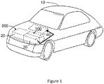
- FIG. 1 there is shown a perspective illustration of an electric vehicle 10 having a rechargeable electric battery system 200 and a control system 100 therefor.
- FIG. 2 there is shown a schematic illustration of the control system 100 for the rechargeable electric battery system 200.
- the rechargeable electric battery system 200 comprises: a rechargeable electric battery 20, a temperature management system 40 for the rechargeable electric battery 20 and one or more sensors 30 for measuring one or more variables or characteristics relating to the rechargeable electric battery 20.
- the rechargeable electric battery system 200 may additionally comprise a battery management system (BMS) not shown.
- the control unit 50 of the control system 100 (and optionally the entire control system 100) may be integrated within the battery management system (BMS).
- the BMS of the battery pack 20 may comprise additional components for example, electronic circuitry for managing, controlling and balancing the electric charge stored in and discharged from the individual cells of the battery pack 20.
- the BMS may be coupled to one or more of the one or more sensors 30.
- the battery pack 20 comprises a plurality of sealed rechargeable electrochemical energy storage cells (not shown).
- the rechargeable electrochemical energy storage cells may also be referred to herein as cells, pouches and cell pouches.
- each cell may be a Li-ion (Lithium-ion) based electrochemical energy storage cell.
- alternative suitable electrochemical storage cells or combinations thereof may be used.
- the temperature management system 40 is provided to adjust or control the temperature of the cells contained in the battery pack 20.
- the one or more sensors 30 may comprise temperature sensors (not shown) integrated into the battery pack 20. As such, at least part of the temperature management system 40 may be integrated within battery pack 20.
- the one or more sensors 30 may be coupled directly or indirectly to one or more of the cells of the battery pack 20 for measuring, for example: individual cell temperature; voltage; individual cell impedance; and individual cell state-of-charge (capacitance).
- the control system 100 comprises a control unit 50 configured and arranged to receive data from the one or more sensors 30.
- the control unit 50 may be communicatively coupled to the one or more sensors 30.
- Information from one or more sensors 30 may be transmitted directly to the control unit 50 of the present invention from another vehicle control system having that data (for example, the battery management system) or information may be transmitted via an associated controller via a vehicle CAN-bus or similar vehicle-based data network.
- the control system 100 is provided with measurements of one or more variables that are related to performance characteristics of the battery 20.
- the control unit 50 is coupled to the temperature management system 40 for controlling the cooling strategy implemented by the temperature management system 40.
- the control unit 50 optionally comprises a processor and memory 60 and is configured and arranged to determine in dependence upon data received from the one or more sensors 30 a time-weighted-average state-of-health of the rechargeable electric battery 20. In dependence upon the determined time-weighted-average state-of-health of the rechargeable electric battery 20, the control unit 50 is configured and arranged to manage the cooling strategy performed by the temperature management system 40. Thereby the temperature of the rechargeable electric battery 20 is managed for optimising the energy efficiency of the rechargeable electric battery system and/or for optimising the lifetime of the rechargeable electric battery.
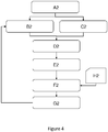
- FIG. 3 an algorithm or method that may be carried out by the processor and memory 60 of the control unit 50 in an embodiment of the invention is shown schematically.
- the control unit 50 is provided with a temperature control strategy A1.
- this may include one or more different set-point temperatures for the temperature management system to be used for specified periods of time during specified circumstances.
- control unit 50 is configured to run an algorithm described as follows:
- the control strategy includes a variety of temperature set points, for a specified range of circumstances.
- the temperature management strategy includes five vehicle scenarios and in dependence upon the relative degradation of the vehicle (quantified by the measured state-of-health) a different temperature management strategy will be selected.
- a first scenario is the temperature set point of the temperature management system 40 during vehicle use;
- a second scenario is the temperature set point of the temperature management system 40 during charging of the battery pack;
- a third scenario is the additional time during which battery pack cooling is set to continue after the battery pack is no longer in use;
- the temperature management system is configured to operate to maintain a particular temperature for a particular time period.
- strategy 1 may be adopted when the vehicle battery pack 20 time-weighted-average state-of-health score is as good as or better than expected for the age of the battery pack 20.
- a scenario may occur when a vehicle 10 is kept in an environment having a moderate or cool climate, wherein the ambient temperature is similar to the preferred temperature of the battery pack 20.
- cooling of the battery pack 20 below the ambient temperature may be unnecessary; (for example, it would not result in an advantage and may only extend the battery lifetime beyond a required lifetime), yet electrical energy to power a cooling system would be used.
- This unnecessary energy consumption may be avoided by adapting strategy 1 in which the temperature set point during battery operation (voltage supply) and battery charging is increased, for example to 35°C from for example 30°C.
- the temperature management system 40 would nevertheless be provided with a maximum temperature threshold for a battery pack 20.
- the maximum temperature threshold may be measured against either average temperature of all of the cells in the battery pack 20 or by any one individual cell. If the maximum temperature threshold is reached an automatic cooling of the battery pack 20 would be invoked irrespective of the adopted temperature management strategy.
- Temperature management strategy 2 may be adopted by the temperature management system 40 (under instruction from the control system 100), where the battery pack has degraded to some extent but not to the degree expected for its age.
- a metric for degradation is that a 2% reduction in state-of-health per year is acceptable. With such a rate of degradation, after a 10 year battery pack lifetime, the battery pack still would operate at 80% of its original capacity. It will be appreciated that for different types and size of battery pack 20 an acceptable lifetime may be different and indeed battery lifetime may be quantified by an alternative metric and may not be quantified as a battery having 80% of the battery's original (charging) capacity at the end of a 10 year period. Temperature Management Strategy No. Temp.
- the state-of-health score is calculated from the following measured characteristics:
- a state-of-health or health score is determined (B1).
- the determined score is recorded and the time at which it was determined is taken (D1).
- the control unit 50 records this data over a period of time and from the recorded data is able to determine a time-weighted-average state-of-health score (E1).
- the state-of-health score may be determined on a daily basis.
- the time period (P) that the state-of-health score is recorded for maybe one month, two months or for example one year (i.e. 365 days).
- the time-weighted-average state of health score is therefore calculated at the end of the time period (P). Because a time-weighted-average is calculated, consideration is given to the percentage of time (e.g., days) out of that time period (P) that a particular state-of-health score was determined.
- the time-averaged state-of-health score of the battery pack will differ from the state-of-health score of a battery in a vehicle 10 kept in the same climate but driven for three hours per day (and hence cooled to a lower than ambient temperature for three hours per day) and recharged daily (and hence having a higher average state-of-charge).
- a temperature management strategy is selected by the control unit 50 (optionally by referencing a look-up table).
- a cooling strategy is selected by the control unit 50 to mitigate against the effects that caused the low time-weighted-average state-of-health score.
- the battery pack 20 of the vehicle 10 that was used for only one hour per week may be subject to additional cooling when the vehicle 10 is not in use (as per, for example, the third strategy listed above).
- a high health score may in fact be indicative of degradation and the exact scale used to quantify the state-of-health of a battery pack 20 may differ from that described here.
- control unit 50 is configured automatically to effect such "non-vehicle-use" cooling.
- a control panel within the vehicle's 10 cabin may issue a notice to a user of the vehicle 10 requesting the user to activate or agree to the "over cooling”.
- the control unit 50 may be configured to automatically effect the additional temperature management of the battery pack 20 when the vehicle 10 is not in use.
- P next successive time period
- the time-weighted-average state-of-health of the battery pack 20 at the end of the second time period may be significantly improved compared to what it would otherwise have been.
- the control unit 50 upon determining the time-weighted-average state-of-health score for the second time period (E1) will then determine a required battery cooling strategy (F1).
- the cooling strategies may be recorded in a look-up table, optionally stored in the memory 60 of the control system 100.
- the battery cooling strategy may stay the same; revert to the original cooling strategy; or change to a different strategy to implement even further over-cooling.
- the control system 100 is configured to take into consideration the preceding temperature management strategies that have been employed.
- control unit 50 upon determining a time-weighted-average state-of-health score, is configured to change the time period (P) in which the next successive time-weighted-average state-of-health score should be determined.
- the time period (P) may be reduced from annually to bi-annually or from monthly to weekly.
- time-weighted-average state-of-health may be determined about or exactly at: weekly, monthly, bi-monthly, tri-monthly, bi-annually or annually. Additionally or alternatively, in other envisaged embodiments, the time-weighted state-of-health score may be determined in dependence upon the distance travelled by the vehicle.
- the control system 100 is configured to execute a different algorithm.
- the temperature management strategy (A2) comprises selection of only different set-point temperatures (in dependence upon the time-weighted-average state-of-health score determined after a time period (P)). No cooling during holiday periods or non-vehicle use periods or run-on time management is performed. More simply at a time period (P) a time-weighted-average state-of-health score is determined (E2), based upon the recorded state-of-health score (B2, D2, C2). In this embodiment the state-of-health score is optionally determined based upon the following three factors:
- the state-of-health-score may be determined from the above characteristics by first scoring each characteristic. The individual characteristic scores may then be summed, averaged or otherwise mathematically combined to create an overall state-of-health-score.
- the control unit 50 may refer to a look-up table such as that set out below to determine the required temperature set point to be used by the temperature management system 40.
- the temperature set points are preferably listed against values (or ranges) of rate of battery health degradation.
- the determined time-weighted-average state-of-health degradation rate is optionally calculated relative to the originally determined state-of-health of the battery at a given time period, for example at manufacture.
- the determined state-of-health is compared to an expected or required state-of-health for the age of the battery pack 20. For example, for a 10 year battery life time, an acceptable rate of state-of-health degradation may be about -2% per year.
- This optional bench mark (-2% degradation in SoH per year) is used in the present embodiment to determine the cooling set-point that the control unit 50 should instruct the temperature management system 40 to maintain the battery pack 20 at (during use of the vehicle 10).
- the control unit 50 may reference a look-up table such as the following: Rate of SoH Degradation Temperature Set Point 0% Not Applicable (DEFAULT Temp) -1% about 35°C -2% about 30°C -3% about 27°C -4% about 25°C
- determining a state-of-health score or otherwise quantifying the state-of-health of a battery pack 20 may be achieved in many and various suitable ways and using one or more of a variety of battery pack 20 characteristics.
- any data values from the one or more sensors 30 may be rounded and/or averaged. It will be recognised that in computing any metric, for example state-of-health (score) and time-weighted-average state-of-health (score) that computed values may be rounded.
- the look-up table may be stored remotely and/or locally.
- the look-up table may be updateable, for example during servicing of the vehicle 10 an update may be installed.
- control unit 50 may be configured to compute a desired temperature management strategy or compute at least part of the temperature management strategy based on an algorithm pre-programmed into the control unit 50.
- the state-of-health of the battery pack 20 is determined solely in dependence upon a time-weighted-average temperature of the battery pack 20.
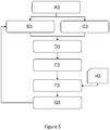
- Figure 5 shows schematically at least part of an algorithm or method that may be carried out by the processor and memory 60 of the control unit 50 in another embodiment of the invention.
- An initial temperature set point (A3) is provided for the temperature management system 40.
- the temperature of the battery pack 20 is measured (B3). This may be achieved by the BMS monitoring data from thermistors coupled to each individual cell of the battery pack 20, periodically, for a given time period (for example one day). The BMS may then issue to the control unit 50, an average battery pack temperature for that day.
- the control unit 50 records the time of the measurement (C3), for example day-one, and the Pack Temperature. Based upon a collated data set of temperature over time (D3), the control unit 50 is configured to compute a time-weighted-average state-of-health (E3). In this embodiment the time-weighted-average state-of-health is equivalent to a time-weighted-average battery pack temperature.
- a temperature set point for the temperature management system 40 is determined by the control unit 50 (F3).
- the control unit 50 may compute the temperature set point and/or may reference a look-up table (H3).
- the control unit 50 then may issue a revised temperature set point to the temperature management system (G3) for the coming time period (P).
- the control system 100 continues to monitor the health of the battery pack 20 and adopt an appropriate temperature management strategy either to optimise the energy efficiency or to improve the battery life time.
- vehicles 10 can be transferred to different climates and that climates change. Furthermore subject to vehicle 10 usage and care the battery pack 20 health may change. It is envisaged therefore that during a battery pack 20 lifetime different temperature management strategies may be employed and during one period this may be to optimise energy efficiency and during another (preceding or succeeding) period the strategy may be to optimise battery lifetime.
- the one or more sensors 30 are contained in other control systems of the vehicle for example, but not limited to a temperature sensor to monitor the ambient temperature of the vehicle 10.
- cooling system 40 has been used herein this should be taken as being synonymous with temperature management system 40.
- the temperature management system 40 may be configured to heat and/or cool a battery pack.
Landscapes
- Engineering & Computer Science (AREA)
- Manufacturing & Machinery (AREA)
- Chemical & Material Sciences (AREA)
- Chemical Kinetics & Catalysis (AREA)
- Electrochemistry (AREA)
- General Chemical & Material Sciences (AREA)
- Power Engineering (AREA)
- Mechanical Engineering (AREA)
- Transportation (AREA)
- Sustainable Energy (AREA)
- Sustainable Development (AREA)
- Life Sciences & Earth Sciences (AREA)
- Physics & Mathematics (AREA)
- General Physics & Mathematics (AREA)
- Secondary Cells (AREA)
- Charge And Discharge Circuits For Batteries Or The Like (AREA)
- Electric Propulsion And Braking For Vehicles (AREA)
Claims (14)
- Steuersystem (100) für ein wiederaufladbares elektrisches Batteriesystem (200) für ein Fahrzeug (10), wobei das wiederaufladbare elektrische Batteriesystem Folgendes umfasst:eine wiederaufladbare elektrische Batterie (20);ein Temperaturverwaltungssystem (40) für die wiederaufladbare elektrische Batterie; undeinen oder mehrere Sensoren (30) zum Messen einer oder mehrerer Eigenschaften bezüglich der wiederaufladbaren elektrischen Batterie,wobei das Steuersystem eine Steuereinheit (50) umfasst, die mit dem Temperaturverwaltungssystem koppelbar ist und zu Folgendem angeordnet ist:Empfangen von Daten von dem einen und/oder den mehreren Sensoren;Bestimmen eines zeitlich gemittelten Gesundheitszustandes der wiederaufladbaren elektrischen Batterie in Abhängigkeit von den empfangenen Daten; undVerwalten des Temperaturverwaltungssystems in Abhängigkeit von dem bestimmten zeitlich gemittelten Gesundheitszustand der wiederaufladbaren elektrischen Batterie;dadurch gekennzeichnet, dass die Steuereinheit konfiguriert ist, um eine Abweichung des bestimmten zeitlich gemittelten Gesundheitszustandes der wiederaufladbaren elektrischen Batterie von einem erwarteten zeitlich gemittelten Gesundheitszustand der wiederaufladbaren elektrischen Batterie zu bestimmen, und die Steuereinheit konfiguriert ist, um eine eingestellte Punkttemperatur des Temperaturverwaltungssystems auf Grundlage der bestimmten Abweichung zu modifizieren, wobei der erwartete zeitliche gemittelte Gesundheitszustand der wiederaufladbaren elektrischen Batterie (20) in Abhängigkeit von dem Alter der wiederaufladbaren elektrischen Batterie (20) bestimmt wird, und wobei das Alter in Bezug auf Zeit, die seit der ersten Verwendung der wiederaufladbaren elektrischen Batterie (20) vergangen ist, und/oder in Bezug auf eine Entfernung, die durch ein Fahrzeug (10), das die wiederaufladbare elektrische Batterie (20) umfasst, zurückgelegt wurde, quantifiziert wird.
- Steuersystem (100) nach Anspruch 1, wobei die Steuereinheit (50) konfiguriert ist, die eingestellte Punkttemperatur des Temperaturverwaltungssystems (40) herabzusetzen, wenn der bestimmte Gesundheitszustand einen größeren Leistungsrückgang der wiederaufladbaren elektrischen Batterie anzeigt, als durch den erwarteten zeitlich gemittelten Gesundheitszustand angezeigt wird, um die Lebensdauer der wiederaufladbaren elektrischen Batterie zu optimieren.
- Steuersystem (100) nach Anspruch 1, wobei die Steuereinheit (50) konfiguriert ist, die eingestellte Punkttemperatur des Temperaturverwaltungssystems (40) heraufzusetzen, wenn der bestimmte Gesundheitszustand einen niedrigeren Leistungsrückgang der wiederaufladbaren elektrischen Batterie anzeigt, als durch den erwarteten zeitlich gemittelten Gesundheitszustand angezeigt wird, um die Wirksamkeit des wiederaufladbaren elektrischen Batteriesystems (200) zu optimieren.
- Steuersystem (100) nach einem der vorhergehenden Ansprüche, wobei die erwartete zeitlich gemittelte Gesundheitszustandsänderung im Laufe eines Jahres proportional zu einem ursprünglichen Gesundheitszustand der wiederaufladbaren elektrischen Batterie (20) ist.
- Steuersystem (100) nach Anspruch 4, wobei der ursprüngliche Gesundheitszustand der wiederaufladbaren elektrischen Batterie (20) bestimmt wird, wenn die wiederaufladbare elektrische Batterie zuerst verwendet wird oder innerhalb eines eingestellten Zeitraumes von der ersten Verwendung der wiederaufladbaren elektrischen Batterie an.
- Steuersystem (100) nach einem der vorhergehenden Ansprüche, wobei die eine oder die mehreren Eigenschaften bezüglich der wiederaufladbaren elektrischen Batterie (20) eine oder mehrere oder eine Kombination von Folgendem enthalten:(i) die Durchschnittstemperatur aller Zellen, die in der wiederaufladbaren elektrischen Batterie enthalten sind;(ii) die höchste Temperatur einer individuellen Zelle, die in der wiederaufladbaren elektrischen Batterie enthalten ist;(iii) die niedrigste Temperatur einer individuellen Zelle, die in der wiederaufladbaren elektrischen Batterie enthalten ist;(iv) die Differenz zwischen der höchsten Temperatur einer individuellen Zelle und der niedrigsten Temperatur einer individuellen Zelle;(v) den Durchschnittsladezustand aller Zellen, die in der wiederaufladbaren elektrischen Batterie enthalten sind;(vi) den höchste Ladezustand einer individuellen Zelle, die in der wiederaufladbaren elektrischen Batterie enthalten ist;(vii) den niedrigste Ladezustand einer individuellen Zelle, die in der wiederaufladbaren elektrischen Batterie enthalten ist;(viii) die Differenz zwischen dem höchsten Ladezustand einer individuellen Zelle und dem niedrigsten Ladezustand einer individuellen Zelle;(ix) die durchschnittliche Spannungsausgabe aller Zellen, die in der wiederaufladbaren elektrischen Batterie enthalten sind;(x) die höchste Spannungsausgabe einer individuellen Zelle, die in der wiederaufladbaren elektrischen Batterie enthalten ist;(xi) die niedrigste Spannungsausgabe einer individuellen Zelle, die in der wiederaufladbaren elektrischen Batterie enthalten ist;(xii) die Differenz zwischen der höchsten Spannungsausgabe einer individuellen Zelle und der niedrigsten Spannungsausgabe einer individuellen Zelle;(xii) die Anzahl der Zellen, die in der wiederaufladbaren elektrischen Batterie enthalten sind; und(xiv) die Anzahl von chemisch oder physikalisch verminderten oder defekten Zellen in der wiederaufladbaren elektrischen Batterie.
- Steuersystem (100) nach einem der vorhergehenden Ansprüche, umfassend einen oder mehrere Hilfssensoren (30), die mit der Steuereinheit gekoppelt sind und fähig sind, Daten an die Steuereinheit bezüglich einer oder mehrerer Eigenschaften der Fahrzeugumgebung auszugeben.
- Steuersystem (100) nach Anspruch 2 oder einem der Ansprüche 4 bis 7, wenn abhängig von Anspruch 2, umfassend einen Hilfssensor (30) zum Messen der Umgebungstemperatur der Umgebung um das Fahrzeug herum.
- Steuersystem (100) nach einem der vorhergehenden Ansprüche, wobei die Steuereinheit (50) konfiguriert ist, das Temperaturverwaltungssystem (40) durch Bestimmen eines oder mehrerer oder einer Kombination von folgenden Parametern zu verwalten:(i) Temperatureinstellpunkt, wenn das Fahrzeug (10) gefahren wird und/oder das Fahrzeug eingeschaltet ist;(ii) Temperatureinstellpunkt während des Ladens der wiederaufladbaren elektrischen Batterie (20);(iii) Nachlaufzeit des Temperaturverwaltungssystems;(iv) Temperatureinstellpunkt während eines Zeitraumes, in dem das Fahrzeug nicht in Verwendung ist; und(v) Strategie oder Modus während eines Zeitraumes, in dem das Fahrzeug nicht in Verwendung ist.
- Steuersystem (100) nach einem der vorhergehenden Ansprüche, wobei einer der Sensoren (30) Echtzeitdaten an die Steuereinheit (50) bereitstellt oder wobei einer der Sensoren zeitlich gemittelte Daten an die Steuereinheit bereitstellt.
- Verfahren zum Steuern eines wiederaufladbaren elektrischen Batteriesystems (200), Folgendes umfassend: eine wiederaufladbare elektrische Batterie (20), ein Temperaturverwaltungssystem (40) für die wiederaufladbare elektrische Batterie und einen oder mehrere Sensoren (30) zum Messen einer oder mehrerer Eigenschaften bezüglich der wiederaufladbaren elektrischen Batterie, wobei das Verfahren Folgendes umfasst:Erhalten von Daten von dem einen und/oder den mehreren Sensoren;Bestimmen eines zeitlich gemittelten Gesundheitszustandes der wiederaufladbaren elektrischen Batterie in Abhängigkeit von den Daten;Steuern einer benötigten Temperatur der wiederaufladbaren elektrischen Batterie in Abhängigkeit von dem bestimmten zeitlich gemittelten Gesundheitszustand der wiederaufladbaren elektrischen Batterie,dadurch gekennzeichnet, dass das Verfahren ferner Folgendes umfasst: Bestimmen einer Abweichung des bestimmten zeitlich gemittelten Gesundheitszustandes der wiederaufladbaren elektrischen Batterie von einem erwarteten zeitlich gemittelten Gesundheitszustand der wiederaufladbaren elektrischen Batterie, und Modifizieren einer eingestellten Punkttemperatur des Temperaturverwaltungssystems auf Grundlage der bestimmten Abweichung, wobei der erwartete zeitliche gemittelte Gesundheitszustand der wiederaufladbaren elektrischen Batterie (20) in Abhängigkeit von dem Alter der wiederaufladbaren elektrischen Batterie (20) bestimmt wird und wobei das Alter in Bezug auf Zeit, die seit der ersten Verwendung der wiederaufladbaren elektrischen Batterie (20) vergangen ist, und/oder in Bezug auf eine Entfernung, die durch ein Fahrzeug (10), das die wiederaufladbare elektrische Batterie (20) umfasst, zurückgelegt wurde, quantifiziert wird.
- Fahrzeug, umfassend ein wiederaufladbares elektrisches Batteriesystem (200) und ein Steuersystem (100) davon nach einem der Ansprüche 1 bis 10.
- Fahrzeug (10), umfassend ein wiederaufladbares elektrisches Batteriesystem (200) und konfiguriert, das Verfahren nach Anspruch 11 auszuführen.
- Programm für eine Steuereinheit (50) zum Verwenden in einem Steuersystem (100) nach einem der Ansprüche 1 bis 10 und konfiguriert, das Verfahren nach Anspruch 11 auszuführen, wenn in Verwendung.
Applications Claiming Priority (2)
| Application Number | Priority Date | Filing Date | Title |
|---|---|---|---|
| GB1213919.2A GB2504689B (en) | 2012-08-06 | 2012-08-06 | Control of rechargeable electric battery system for a vehicle |
| PCT/EP2013/066509 WO2014023746A2 (en) | 2012-08-06 | 2013-08-06 | Control of rechargeable electric battery system for a vehicle |
Publications (2)
| Publication Number | Publication Date |
|---|---|
| EP2879898A2 EP2879898A2 (de) | 2015-06-10 |
| EP2879898B1 true EP2879898B1 (de) | 2019-02-27 |
Family
ID=46934888
Family Applications (1)
| Application Number | Title | Priority Date | Filing Date |
|---|---|---|---|
| EP13745139.9A Active EP2879898B1 (de) | 2012-08-06 | 2013-08-06 | Steuerung eines akkumulatorsystems für ein fahrzeug |
Country Status (4)
| Country | Link |
|---|---|
| US (1) | US9834099B2 (de) |
| EP (1) | EP2879898B1 (de) |
| GB (1) | GB2504689B (de) |
| WO (1) | WO2014023746A2 (de) |
Families Citing this family (14)
| Publication number | Priority date | Publication date | Assignee | Title |
|---|---|---|---|---|
| DE102014214319A1 (de) * | 2014-07-23 | 2016-01-28 | Robert Bosch Gmbh | Batterie mit mehreren Batteriezelleinheiten mit jeweils einer Batteriezelle und einem der Batteriezelle zugeordneten Batteriezellüberwachungsmodul und entsprechendes Verfahren zum Schalten der Batteriezellen einer solchen Batterie |
| KR101628489B1 (ko) * | 2014-09-25 | 2016-06-08 | 현대자동차주식회사 | 차량용 고전압 배터리 제어 장치 및 방법 |
| US10587135B2 (en) * | 2015-09-11 | 2020-03-10 | Microsoft Technology Licensing, Llc | Adaptive battery charging |
| DE102016112173A1 (de) * | 2016-07-04 | 2018-01-04 | Dr. Ing. H.C. F. Porsche Aktiengesellschaft | Verfahren zur Einstellung |
| KR20180057046A (ko) * | 2016-11-21 | 2018-05-30 | 삼성전자주식회사 | 배터리 온도 제어 방법 및 장치 |
| CN108550927B (zh) * | 2018-05-02 | 2020-07-14 | 苏州正力新能源科技有限公司 | 新能源汽车用动力锂电池\系统的热管理方法 |
| US11437656B2 (en) * | 2018-10-29 | 2022-09-06 | International Business Machines Corporation | Optimizing performance of a data center battery system |
| EP3865338A1 (de) * | 2020-02-13 | 2021-08-18 | Ningbo Geely Automobile Research & Development Co. Ltd. | Fahrzeugsteuerungssystem zur optimierung des energieverbrauchs |
| CN111641004A (zh) * | 2020-06-24 | 2020-09-08 | 阳光电源股份有限公司 | 一种储能系统温控方法和能量管理系统 |
| US20240195206A1 (en) * | 2021-04-23 | 2024-06-13 | Cummins Inc. | Methods and systems of aging-aware charging profile determination for a battery system |
| US11912164B2 (en) | 2021-09-27 | 2024-02-27 | Ford Global Technologies, Llc | Electrified vehicle with battery thermal management system configured to adjust temperature thresholds based on battery state of health |
| JP7476917B2 (ja) * | 2022-03-16 | 2024-05-01 | いすゞ自動車株式会社 | 車載のバッテリーの制御装置 |
| US20240217388A1 (en) * | 2022-12-29 | 2024-07-04 | Volkswagen Aktiengesellschaft | Probabilistic modelling of electric vehicle charging and driving usage behavior with hidden markov model-based clustering |
| FR3156717A1 (fr) | 2023-12-18 | 2025-06-20 | Commissariat A L'energie Atomique Et Aux Energies Alternatives | Procédé de gestion thermique d’une batterie d’un appareil électrique |
Family Cites Families (7)
| Publication number | Priority date | Publication date | Assignee | Title |
|---|---|---|---|---|
| JP3949488B2 (ja) | 2002-03-29 | 2007-07-25 | 本田技研工業株式会社 | 蓄電池の寿命予測装置および蓄電池の制御装置 |
| JP4589872B2 (ja) * | 2006-01-04 | 2010-12-01 | 本田技研工業株式会社 | 電動車両の制御装置 |
| JP4265629B2 (ja) | 2006-08-01 | 2009-05-20 | トヨタ自動車株式会社 | 二次電池の充放電制御装置およびそれを搭載したハイブリッド車両 |
| KR100796668B1 (ko) * | 2006-09-26 | 2008-01-22 | 삼성에스디아이 주식회사 | 배터리 관리 시스템 및 그의 구동 방법 |
| JP4228086B1 (ja) * | 2007-08-09 | 2009-02-25 | トヨタ自動車株式会社 | 車両 |
| US8947023B2 (en) * | 2009-10-14 | 2015-02-03 | Hitachi, Ltd. | Battery control device and motor drive system |
| NL2004503C2 (en) * | 2010-04-02 | 2011-10-04 | Epyon B V | Method and device for charging a battery and battery charger. |
-
2012
- 2012-08-06 GB GB1213919.2A patent/GB2504689B/en active Active
-
2013
- 2013-08-06 US US14/419,734 patent/US9834099B2/en active Active
- 2013-08-06 WO PCT/EP2013/066509 patent/WO2014023746A2/en not_active Ceased
- 2013-08-06 EP EP13745139.9A patent/EP2879898B1/de active Active
Non-Patent Citations (1)
| Title |
|---|
| None * |
Also Published As
| Publication number | Publication date |
|---|---|
| WO2014023746A2 (en) | 2014-02-13 |
| GB201213919D0 (en) | 2012-09-19 |
| EP2879898A2 (de) | 2015-06-10 |
| WO2014023746A3 (en) | 2014-06-19 |
| GB2504689B (en) | 2015-07-29 |
| GB2504689A (en) | 2014-02-12 |
| US9834099B2 (en) | 2017-12-05 |
| US20150165919A1 (en) | 2015-06-18 |
Similar Documents
| Publication | Publication Date | Title |
|---|---|---|
| EP2879898B1 (de) | Steuerung eines akkumulatorsystems für ein fahrzeug | |
| US12466293B2 (en) | Thermal management of a component of electrical power system, controller, system, and method | |
| US12237477B2 (en) | State of charge dependent plating estimation and prevention | |
| US20230191943A1 (en) | Battery module lithium plating reduction | |
| US10300807B2 (en) | Systems and methods for state of charge and capacity estimation of a rechargeable battery | |
| US8937452B2 (en) | Method of controlling a state-of-charge (SOC) of a vehicle battery | |
| Padovani et al. | Optimal energy management strategy including battery health through thermal management for hybrid vehicles | |
| US10059222B2 (en) | Battery temperature estimation system | |
| US11173775B2 (en) | Closed loop feedback control to mitigate lithium plating in electrified vehicle battery | |
| US7911184B2 (en) | Battery charging time optimization system | |
| JP6978339B2 (ja) | 二次電池の充電状態推定装置及び異常検出装置、及び二次電池の管理システム | |
| US8405355B2 (en) | Energy storage system energy capacity and capability monitor | |
| US10081268B2 (en) | Management device for secondary battery | |
| US20090013521A1 (en) | Reconstituted battery pack, reconstituted battery pack producing method, reconstituted battery pack using method, and reconstituted battery pack control system | |
| US20170120773A1 (en) | Optimization of cruising voltage for life and fuel economy performance in advanced start-stop systems | |
| CN107000599A (zh) | 蓄电池系统的冷却策略 | |
| WO2011155186A1 (en) | Charging control system | |
| US9197078B2 (en) | Battery parameter estimation | |
| KR20140053590A (ko) | 배터리 잔존 용량 추정 장치 및 방법 | |
| US10205333B2 (en) | Battery controlling device | |
| US20220161682A1 (en) | A method for management of an energy storage system of a vehicle | |
| JP6447446B2 (ja) | 車両用電池制御装置 | |
| US11511647B2 (en) | Adaptive thermal management of an electric energy supply, controller, system, and method | |
| JP2012054019A (ja) | バッテリ | |
| JP4874646B2 (ja) | 電池用制御装置、電動車両、及び二次電池の制御方法 |
Legal Events
| Date | Code | Title | Description |
|---|---|---|---|
| PUAI | Public reference made under article 153(3) epc to a published international application that has entered the european phase |
Free format text: ORIGINAL CODE: 0009012 |
|
| 17P | Request for examination filed |
Effective date: 20150306 |
|
| AK | Designated contracting states |
Kind code of ref document: A2 Designated state(s): AL AT BE BG CH CY CZ DE DK EE ES FI FR GB GR HR HU IE IS IT LI LT LU LV MC MK MT NL NO PL PT RO RS SE SI SK SM TR |
|
| AX | Request for extension of the european patent |
Extension state: BA ME |
|
| DAX | Request for extension of the european patent (deleted) | ||
| STAA | Information on the status of an ep patent application or granted ep patent |
Free format text: STATUS: EXAMINATION IS IN PROGRESS |
|
| 17Q | First examination report despatched |
Effective date: 20180206 |
|
| GRAP | Despatch of communication of intention to grant a patent |
Free format text: ORIGINAL CODE: EPIDOSNIGR1 |
|
| STAA | Information on the status of an ep patent application or granted ep patent |
Free format text: STATUS: GRANT OF PATENT IS INTENDED |
|
| INTG | Intention to grant announced |
Effective date: 20180926 |
|
| GRAS | Grant fee paid |
Free format text: ORIGINAL CODE: EPIDOSNIGR3 |
|
| GRAA | (expected) grant |
Free format text: ORIGINAL CODE: 0009210 |
|
| STAA | Information on the status of an ep patent application or granted ep patent |
Free format text: STATUS: THE PATENT HAS BEEN GRANTED |
|
| RBV | Designated contracting states (corrected) |
Designated state(s): AL AT BE BG CH CY CZ DE DK EE ES FI FR GR HR HU IE IS IT LI LT LU LV MC MK MT NL NO PL PT RO RS SE SI SK SM TR |
|
| AK | Designated contracting states |
Kind code of ref document: B1 Designated state(s): AL AT BE BG CH CY CZ DE DK EE ES FI FR GR HR HU IE IS IT LI LT LU LV MC MK MT NL NO PL PT RO RS SE SI SK SM TR |
|
| REG | Reference to a national code |
Ref country code: CH Ref legal event code: EP |
|
| REG | Reference to a national code |
Ref country code: AT Ref legal event code: REF Ref document number: 1100821 Country of ref document: AT Kind code of ref document: T Effective date: 20190315 |
|
| REG | Reference to a national code |
Ref country code: IE Ref legal event code: FG4D |
|
| REG | Reference to a national code |
Ref country code: DE Ref legal event code: R096 Ref document number: 602013051410 Country of ref document: DE |
|
| REG | Reference to a national code |
Ref country code: NL Ref legal event code: MP Effective date: 20190227 |
|
| REG | Reference to a national code |
Ref country code: LT Ref legal event code: MG4D |
|
| PG25 | Lapsed in a contracting state [announced via postgrant information from national office to epo] |
Ref country code: NO Free format text: LAPSE BECAUSE OF FAILURE TO SUBMIT A TRANSLATION OF THE DESCRIPTION OR TO PAY THE FEE WITHIN THE PRESCRIBED TIME-LIMIT Effective date: 20190527 Ref country code: FI Free format text: LAPSE BECAUSE OF FAILURE TO SUBMIT A TRANSLATION OF THE DESCRIPTION OR TO PAY THE FEE WITHIN THE PRESCRIBED TIME-LIMIT Effective date: 20190227 Ref country code: LT Free format text: LAPSE BECAUSE OF FAILURE TO SUBMIT A TRANSLATION OF THE DESCRIPTION OR TO PAY THE FEE WITHIN THE PRESCRIBED TIME-LIMIT Effective date: 20190227 Ref country code: SE Free format text: LAPSE BECAUSE OF FAILURE TO SUBMIT A TRANSLATION OF THE DESCRIPTION OR TO PAY THE FEE WITHIN THE PRESCRIBED TIME-LIMIT Effective date: 20190227 Ref country code: PT Free format text: LAPSE BECAUSE OF FAILURE TO SUBMIT A TRANSLATION OF THE DESCRIPTION OR TO PAY THE FEE WITHIN THE PRESCRIBED TIME-LIMIT Effective date: 20190627 Ref country code: NL Free format text: LAPSE BECAUSE OF FAILURE TO SUBMIT A TRANSLATION OF THE DESCRIPTION OR TO PAY THE FEE WITHIN THE PRESCRIBED TIME-LIMIT Effective date: 20190227 |
|
| PG25 | Lapsed in a contracting state [announced via postgrant information from national office to epo] |
Ref country code: RS Free format text: LAPSE BECAUSE OF FAILURE TO SUBMIT A TRANSLATION OF THE DESCRIPTION OR TO PAY THE FEE WITHIN THE PRESCRIBED TIME-LIMIT Effective date: 20190227 Ref country code: BG Free format text: LAPSE BECAUSE OF FAILURE TO SUBMIT A TRANSLATION OF THE DESCRIPTION OR TO PAY THE FEE WITHIN THE PRESCRIBED TIME-LIMIT Effective date: 20190527 Ref country code: GR Free format text: LAPSE BECAUSE OF FAILURE TO SUBMIT A TRANSLATION OF THE DESCRIPTION OR TO PAY THE FEE WITHIN THE PRESCRIBED TIME-LIMIT Effective date: 20190528 Ref country code: HR Free format text: LAPSE BECAUSE OF FAILURE TO SUBMIT A TRANSLATION OF THE DESCRIPTION OR TO PAY THE FEE WITHIN THE PRESCRIBED TIME-LIMIT Effective date: 20190227 Ref country code: LV Free format text: LAPSE BECAUSE OF FAILURE TO SUBMIT A TRANSLATION OF THE DESCRIPTION OR TO PAY THE FEE WITHIN THE PRESCRIBED TIME-LIMIT Effective date: 20190227 Ref country code: IS Free format text: LAPSE BECAUSE OF FAILURE TO SUBMIT A TRANSLATION OF THE DESCRIPTION OR TO PAY THE FEE WITHIN THE PRESCRIBED TIME-LIMIT Effective date: 20190627 |
|
| REG | Reference to a national code |
Ref country code: AT Ref legal event code: MK05 Ref document number: 1100821 Country of ref document: AT Kind code of ref document: T Effective date: 20190227 |
|
| PG25 | Lapsed in a contracting state [announced via postgrant information from national office to epo] |
Ref country code: EE Free format text: LAPSE BECAUSE OF FAILURE TO SUBMIT A TRANSLATION OF THE DESCRIPTION OR TO PAY THE FEE WITHIN THE PRESCRIBED TIME-LIMIT Effective date: 20190227 Ref country code: AL Free format text: LAPSE BECAUSE OF FAILURE TO SUBMIT A TRANSLATION OF THE DESCRIPTION OR TO PAY THE FEE WITHIN THE PRESCRIBED TIME-LIMIT Effective date: 20190227 Ref country code: DK Free format text: LAPSE BECAUSE OF FAILURE TO SUBMIT A TRANSLATION OF THE DESCRIPTION OR TO PAY THE FEE WITHIN THE PRESCRIBED TIME-LIMIT Effective date: 20190227 Ref country code: RO Free format text: LAPSE BECAUSE OF FAILURE TO SUBMIT A TRANSLATION OF THE DESCRIPTION OR TO PAY THE FEE WITHIN THE PRESCRIBED TIME-LIMIT Effective date: 20190227 Ref country code: SK Free format text: LAPSE BECAUSE OF FAILURE TO SUBMIT A TRANSLATION OF THE DESCRIPTION OR TO PAY THE FEE WITHIN THE PRESCRIBED TIME-LIMIT Effective date: 20190227 Ref country code: IT Free format text: LAPSE BECAUSE OF FAILURE TO SUBMIT A TRANSLATION OF THE DESCRIPTION OR TO PAY THE FEE WITHIN THE PRESCRIBED TIME-LIMIT Effective date: 20190227 Ref country code: ES Free format text: LAPSE BECAUSE OF FAILURE TO SUBMIT A TRANSLATION OF THE DESCRIPTION OR TO PAY THE FEE WITHIN THE PRESCRIBED TIME-LIMIT Effective date: 20190227 Ref country code: CZ Free format text: LAPSE BECAUSE OF FAILURE TO SUBMIT A TRANSLATION OF THE DESCRIPTION OR TO PAY THE FEE WITHIN THE PRESCRIBED TIME-LIMIT Effective date: 20190227 |
|
| REG | Reference to a national code |
Ref country code: DE Ref legal event code: R097 Ref document number: 602013051410 Country of ref document: DE |
|
| PG25 | Lapsed in a contracting state [announced via postgrant information from national office to epo] |
Ref country code: SM Free format text: LAPSE BECAUSE OF FAILURE TO SUBMIT A TRANSLATION OF THE DESCRIPTION OR TO PAY THE FEE WITHIN THE PRESCRIBED TIME-LIMIT Effective date: 20190227 Ref country code: PL Free format text: LAPSE BECAUSE OF FAILURE TO SUBMIT A TRANSLATION OF THE DESCRIPTION OR TO PAY THE FEE WITHIN THE PRESCRIBED TIME-LIMIT Effective date: 20190227 |
|
| PG25 | Lapsed in a contracting state [announced via postgrant information from national office to epo] |
Ref country code: AT Free format text: LAPSE BECAUSE OF FAILURE TO SUBMIT A TRANSLATION OF THE DESCRIPTION OR TO PAY THE FEE WITHIN THE PRESCRIBED TIME-LIMIT Effective date: 20190227 |
|
| PLBE | No opposition filed within time limit |
Free format text: ORIGINAL CODE: 0009261 |
|
| STAA | Information on the status of an ep patent application or granted ep patent |
Free format text: STATUS: NO OPPOSITION FILED WITHIN TIME LIMIT |
|
| 26N | No opposition filed |
Effective date: 20191128 |
|
| PG25 | Lapsed in a contracting state [announced via postgrant information from national office to epo] |
Ref country code: SI Free format text: LAPSE BECAUSE OF FAILURE TO SUBMIT A TRANSLATION OF THE DESCRIPTION OR TO PAY THE FEE WITHIN THE PRESCRIBED TIME-LIMIT Effective date: 20190227 |
|
| PG25 | Lapsed in a contracting state [announced via postgrant information from national office to epo] |
Ref country code: TR Free format text: LAPSE BECAUSE OF FAILURE TO SUBMIT A TRANSLATION OF THE DESCRIPTION OR TO PAY THE FEE WITHIN THE PRESCRIBED TIME-LIMIT Effective date: 20190227 |
|
| PG25 | Lapsed in a contracting state [announced via postgrant information from national office to epo] |
Ref country code: LU Free format text: LAPSE BECAUSE OF NON-PAYMENT OF DUE FEES Effective date: 20190806 Ref country code: CH Free format text: LAPSE BECAUSE OF NON-PAYMENT OF DUE FEES Effective date: 20190831 Ref country code: MC Free format text: LAPSE BECAUSE OF FAILURE TO SUBMIT A TRANSLATION OF THE DESCRIPTION OR TO PAY THE FEE WITHIN THE PRESCRIBED TIME-LIMIT Effective date: 20190227 Ref country code: LI Free format text: LAPSE BECAUSE OF NON-PAYMENT OF DUE FEES Effective date: 20190831 |
|
| REG | Reference to a national code |
Ref country code: BE Ref legal event code: MM Effective date: 20190831 |
|
| PG25 | Lapsed in a contracting state [announced via postgrant information from national office to epo] |
Ref country code: IE Free format text: LAPSE BECAUSE OF NON-PAYMENT OF DUE FEES Effective date: 20190806 Ref country code: FR Free format text: LAPSE BECAUSE OF NON-PAYMENT OF DUE FEES Effective date: 20190831 |
|
| PG25 | Lapsed in a contracting state [announced via postgrant information from national office to epo] |
Ref country code: BE Free format text: LAPSE BECAUSE OF NON-PAYMENT OF DUE FEES Effective date: 20190831 |
|
| PG25 | Lapsed in a contracting state [announced via postgrant information from national office to epo] |
Ref country code: CY Free format text: LAPSE BECAUSE OF FAILURE TO SUBMIT A TRANSLATION OF THE DESCRIPTION OR TO PAY THE FEE WITHIN THE PRESCRIBED TIME-LIMIT Effective date: 20190227 |
|
| PG25 | Lapsed in a contracting state [announced via postgrant information from national office to epo] |
Ref country code: MT Free format text: LAPSE BECAUSE OF FAILURE TO SUBMIT A TRANSLATION OF THE DESCRIPTION OR TO PAY THE FEE WITHIN THE PRESCRIBED TIME-LIMIT Effective date: 20190227 Ref country code: HU Free format text: LAPSE BECAUSE OF FAILURE TO SUBMIT A TRANSLATION OF THE DESCRIPTION OR TO PAY THE FEE WITHIN THE PRESCRIBED TIME-LIMIT; INVALID AB INITIO Effective date: 20130806 |
|
| PG25 | Lapsed in a contracting state [announced via postgrant information from national office to epo] |
Ref country code: MK Free format text: LAPSE BECAUSE OF FAILURE TO SUBMIT A TRANSLATION OF THE DESCRIPTION OR TO PAY THE FEE WITHIN THE PRESCRIBED TIME-LIMIT Effective date: 20190227 |
|
| P01 | Opt-out of the competence of the unified patent court (upc) registered |
Effective date: 20230528 |
|
| PGFP | Annual fee paid to national office [announced via postgrant information from national office to epo] |
Ref country code: DE Payment date: 20250820 Year of fee payment: 13 |