EP2879734B1 - Druckmesseinheit zur bestimmung des flüssigkeitsdrucks innerhalb einer flüssigkeitsspendervorrichtung - Google Patents
Druckmesseinheit zur bestimmung des flüssigkeitsdrucks innerhalb einer flüssigkeitsspendervorrichtung Download PDFInfo
- Publication number
- EP2879734B1 EP2879734B1 EP13759020.4A EP13759020A EP2879734B1 EP 2879734 B1 EP2879734 B1 EP 2879734B1 EP 13759020 A EP13759020 A EP 13759020A EP 2879734 B1 EP2879734 B1 EP 2879734B1
- Authority
- EP
- European Patent Office
- Prior art keywords
- fluid
- rigid
- membrane
- pressure
- pressure transducer
- Prior art date
- Legal status (The legal status is an assumption and is not a legal conclusion. Google has not performed a legal analysis and makes no representation as to the accuracy of the status listed.)
- Active
Links
Images


Classifications
-
- A—HUMAN NECESSITIES
- A61—MEDICAL OR VETERINARY SCIENCE; HYGIENE
- A61M—DEVICES FOR INTRODUCING MEDIA INTO, OR ONTO, THE BODY; DEVICES FOR TRANSDUCING BODY MEDIA OR FOR TAKING MEDIA FROM THE BODY; DEVICES FOR PRODUCING OR ENDING SLEEP OR STUPOR
- A61M5/00—Devices for bringing media into the body in a subcutaneous, intra-vascular or intramuscular way; Accessories therefor, e.g. filling or cleaning devices, arm-rests
- A61M5/14—Infusion devices, e.g. infusing by gravity; Blood infusion; Accessories therefor
- A61M5/142—Pressure infusion, e.g. using pumps
-
- G—PHYSICS
- G01—MEASURING; TESTING
- G01L—MEASURING FORCE, STRESS, TORQUE, WORK, MECHANICAL POWER, MECHANICAL EFFICIENCY, OR FLUID PRESSURE
- G01L19/00—Details of, or accessories for, apparatus for measuring steady or quasi-steady pressure of a fluent medium insofar as such details or accessories are not special to particular types of pressure gauges
-
- G—PHYSICS
- G01—MEASURING; TESTING
- G01L—MEASURING FORCE, STRESS, TORQUE, WORK, MECHANICAL POWER, MECHANICAL EFFICIENCY, OR FLUID PRESSURE
- G01L19/00—Details of, or accessories for, apparatus for measuring steady or quasi-steady pressure of a fluent medium insofar as such details or accessories are not special to particular types of pressure gauges
- G01L19/0007—Fluidic connecting means
- G01L19/0023—Fluidic connecting means for flowthrough systems having a flexible pressure transmitting element
-
- A—HUMAN NECESSITIES
- A61—MEDICAL OR VETERINARY SCIENCE; HYGIENE
- A61M—DEVICES FOR INTRODUCING MEDIA INTO, OR ONTO, THE BODY; DEVICES FOR TRANSDUCING BODY MEDIA OR FOR TAKING MEDIA FROM THE BODY; DEVICES FOR PRODUCING OR ENDING SLEEP OR STUPOR
- A61M2205/00—General characteristics of the apparatus
- A61M2205/12—General characteristics of the apparatus with interchangeable cassettes forming partially or totally the fluid circuit
-
- A—HUMAN NECESSITIES
- A61—MEDICAL OR VETERINARY SCIENCE; HYGIENE
- A61M—DEVICES FOR INTRODUCING MEDIA INTO, OR ONTO, THE BODY; DEVICES FOR TRANSDUCING BODY MEDIA OR FOR TAKING MEDIA FROM THE BODY; DEVICES FOR PRODUCING OR ENDING SLEEP OR STUPOR
- A61M2205/00—General characteristics of the apparatus
- A61M2205/33—Controlling, regulating or measuring
- A61M2205/3331—Pressure; Flow
-
- A—HUMAN NECESSITIES
- A61—MEDICAL OR VETERINARY SCIENCE; HYGIENE
- A61M—DEVICES FOR INTRODUCING MEDIA INTO, OR ONTO, THE BODY; DEVICES FOR TRANSDUCING BODY MEDIA OR FOR TAKING MEDIA FROM THE BODY; DEVICES FOR PRODUCING OR ENDING SLEEP OR STUPOR
- A61M5/00—Devices for bringing media into the body in a subcutaneous, intra-vascular or intramuscular way; Accessories therefor, e.g. filling or cleaning devices, arm-rests
- A61M5/14—Infusion devices, e.g. infusing by gravity; Blood infusion; Accessories therefor
- A61M5/168—Means for controlling media flow to the body or for metering media to the body, e.g. drip meters, counters ; Monitoring media flow to the body
- A61M5/16831—Monitoring, detecting, signalling or eliminating infusion flow anomalies
- A61M5/16854—Monitoring, detecting, signalling or eliminating infusion flow anomalies by monitoring line pressure
Definitions
- the present invention relates to pressure measurement of a fluid in a medical fluid dispensing device, for instance in a disposable fluid container.
- a disposable set of fluid dispensing device and/or fluid container overcomes this risk but involves some other difficulties, particularly when the assessment of physical quantities is required. Indeed, the disposable set is designed for one use only and needs to be economically manufactured to reduce its cost. For control and monitoring purposes, it is desirable to measure the fluid pressure within the disposable set. However, this set cannot include any transducer which in general is too expensive.
- the disposable set requires one or more pressure transducers to be deported on the device and to find a coupling which allows to estimate physical quantities whereas the pressure transducer is not in direct contact with the fluid. In the case of pressure measurement, two cases may be differentiated:
- a flexible element in the case of overpressure, a flexible element (membrane) can simply be in contact with the pressure transducer (force or pressure). In the case of depression, it is necessary to add a fluid tight coupling around the membrane linking the pressure transducer to the disposable set.
- the application WO 2007/085993 discloses a fluid pressure measuring unit for medical devices which traps an air volume between the pressure transducer's membrane and the disposable set's membrane.
- a sealing element which is slightly compressed ensures the fluid tightness of the system.
- the interface of a disposable set with a medical measurement device requires technical solutions which should be simple and reliable. Specifically for measurement purposes, the design must insure the functionality and controllability.
- a fluid container for a medical fluid dispensing device comprising a rigid body for delimiting with the inside part of its wall a volume of the medical fluid, and a membrane that covers at least an opening of the rigid body thereby creating a fluid tight lid, the opening corresponding to a measurement area, and the membrane further covers a portion of an outside part of the rigid body's wall.
- the membrane comprises a flexible measurement part corresponding to the opening of the rigid body, an attachment part that is fixed to the rigid body, and a second part that connects the flexible measurement part to the attachment part, and which comprises a rigid part, an upper part of which is connected to the flexible measurement part, and the rigid part further comprising a sealing surface, and a deformable part which connects the rigid part to the attachment part.
- the fluid container further comprises a first gap located between the rigid part and the rigid body, which is dimensioned to receive at least a part of the rigid part in a case when a force is applied onto the sealing surface and causes the deformable part to deform.
- the invention provides a fluid pressure measurement unit for measuring either positive or negative fluid pressure of a medical fluid in a fluid container, said unit comprising the fluid container according to the previous paragraph, and a pressure transducer comprising a planar measuring surface.
- the planar measuring surface is positioned against the sealing surface of the rigid part, thereby defining a fluid tight chamber that separates the membrane and the planar measuring surface, and the flexible measurement part is adapted to transmit pressure from the medical fluid to the pressure transducer.
- the rigid part is L-shaped, the upper part of the L being connected to the flexible measurement part, and the lower base part of the L offering the sealing surface.
- the deformable part is in a plane perpendicular to the flexible measurement part.
- the pressure transducer further comprises a sealing protrusion surrounding the planar measuring surface, whereby the sealing protrusion is positioned against the sealing surface of the rigid part, thereby defining the fluid tight chamber (9) that separates the membrane and the planar measuring surface.
- the sealing protrusion has an annular shape and extends vertically.
- the present invention allows to perform a reliable coupling between transducer and disposable which
- any direction referred to herein, such as “top”, “bottom”, “left”, “right”, “upper”, “lower”, and other directions or orientations are described herein for clarity in reference to the figures and are not intended to be limiting of an actual device or system. Devices and systems described herein may be used in a number of directions and orientations.
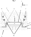
- this shows an example embodiment of a disposable set 19 and a counterpart assembly carrying at least one pressure transducer 2.
- the disposable set 19 comprises at least one fluid container 1 corresponding to the at least one pressure transducer 2, the former which is covered by the membrane 5
- the fluid container 1 is connected to a medical measurement device (not shown), which is equipped with the pressure transducer 2.
- the fluid container 1 comprises:
- the rigid cover plate 6 is an optional feature of the fluid container 1. As such it may well be omitted and/or replaced by other means.
- a planar measuring surface 10 of the medical device (illustrated only partially in the figure) is equipped with the pressure transducer 2.
- a housing of the pressure transducer 2 rests on O-rings 7.
- the O-rings 7 are elastic elements that allow the pressure transducer 2 to be moved and thus imply that the positioning of the pressure transducer 2 may be adapted relative to the fluid container 1's positioning firstly in a plane of the planar measuring surface 10 (herein the plane is defined by x-y axises, illustrated in figure 1 by a coordinate system, whereby the y-axis is perpendicular to the plane of the paper on which the figure is drawn) and secondly in an angle of inclination defined with respect to the planar measuring surface 10 (called ⁇ -angle in the following).
- the pressure transducer 2 comprises a vertical-along the z-axis-sealing protrusion 8 of annular shape.
- the vertical sealing protrusion 8 may be pressed during instrument coupling against a surface of a rigid part 14 of the membrane 5.
- the instrument coupling creates a fluid tight air chamber 9 between the planar measuring surface 10 of the pressure transducer 2, and the membrane 5.
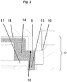
- the membrane 5 comprises a flexible measurement part 11 adapted to transmit pressure from the fluid container 1 to the pressure transducer 2, a second part 12 which is a ring and an attachment part 13 (only shown in figure 1 ) which may be in a plane parallel to the flexible measurement part 11.
- Said flexible measurement part 11 may be circular shape and may have a diameter comprised between 0 to 50 mm, advantageously between 8 to 17 mm.
- the second part 12 comprises the rigid part 14, a sealing surface 18 and a deformable part 15 which may be reversibly and elastically deformed.
- the sealing surface 18 is intended to enter in contact with the vertical sealing protrusion 8.
- the deformable part 15 may be at least partially aligned with the vertical sealing protrusion 8 and both may have the same direction (parallel to the Z-axis).
- the membrane 5 may be made of silicone or other soft material.
- the rigid part 14 may be made of silicone, other soft material or other material which is not or less soft.
- the rigid part 14 of the membrane 5 may be in the form of an L.
- the dimensions of different parts are named according the references “a” to “h”. Said references are examples and may vary.
- the reference “a” may be comprised between 0 to 5 mm, advantageously between 0.5 to 1 mm.
- the reference “b” may be comprised between 0 to 5 mm, advantageously between 0.5 to 1 mm.
- the reference “c” may be comprised between 0 to 10 mm, advantageously between 0.5 to 2 mm.
- the reference “d” may be comprised between 0 to 5 mm, advantageously between 0.1 to 0.5 mm.
- the reference “e” may be comprised between 0 to 5 mm, advantageously between 0.5 to 1 mm.
- the reference “f” may be comprised between 0 to 10 mm, advantageously between 0.5 to 3 mm.
- the reference “g” may be comprised between 0 to 5 mm, advantageously between 0.5 to 1 mm.
- the reference “h” may be comprised between 0 to 10 mm, advantageously between 0.5 to 5 mm.
- the height of sealing protrusion 8 must be at least equal than the reference "a" shown in figure 6 . If said height is equal to "a”, then the fluid tight chamber 9 is equal to 0. In a preferred embodiment, the fluid tight chamber 9 is as small as possible, thus the height of sealing protrusion 8 must be a slightly greater than "a".
- the rigid part 14 is rigid compared to the more flexible measurement part 11, the attachment part 13 and deformable part 15 of the membrane 5.
- the rigidness of rigid part 14 may be achieved by varying the thickness of the material used to produce the rigid part 14, and make sure that the thickness is relatively larger than that of other constituents of the second part 12 and/or than the flexible measurement part 11.
- the rigidness of the rigid part 14 is required to maintain the overall inside volume of the fluid container 1.
- the rigidness and/or the design of the rigid part 14 allows the deformable part 15 to deform while the flexible measurement part 11 not to deform.
- only the pressure of the fluid deforms the flexible measurement part 11.
- a gap in the rigid body 3 has the reference 17 and may be realised as a space between the lower part of the rigid part 14 and the rigid body 3 that allows a movement of the rigid part 14 and the flexible measurement part 11 according to the z-axis, which is perpendicular to the earlier defined x-y-axis-plane (see figure 1 ).
- the movement of the rigid part 14 and the flexible measurement part 11 according to the z-axis is rendered possible also through the feature that the deformable part 15 is deformable in the z-axis direction.
- Said gap 17 may be inside of and/or is a part of the volume of the fluid container 1.
- a further gap exists in the rigid cover plate 6 region.
- the gap in the rigid cover plate 6 region has the reference 16 and may be realised as a bore that allows guiding the pressure transducer 2 during the coupling.
- the rigid cover plate 6 is an optional feature.
- the membrane 5 may well be fixed to the rigid body 3 by any other means, whereby such any other means could for example apply to the attachment part 13.
- Figure 3 contains a schematic representation of the membrane 5 and its second part 12.
- Figure 3 aims at providing a generic explanation that allows a person skilled in the art to reproduce the invention without being tied to the specific preferred embodiment shown in figures 1 and 2 .
- the membrane 5 comprises the flexible measurement part 11. While in figure 2 the property of flexible measurement part 11 to be flexible, i.e., to allow to deform in order to transmit pressure from the fluid container to the pressure transducer, may be achieved by choosing the thickness of the flexible measurement part 11 sufficiently thin to remain elastic to this purpose, in figure 3 , the flexibility is represented by a first spring 30.
- the latter first spring 30 allows the flexible measurement part 11 to remain movable with respect to the rigid part 14, to an extent allowed by the first spring's mechanical properties.
- the membrane 5 further comprises the deformable part 15. While in figure 2 the property of the deformable part 15 to be deformable, i.e., to allow deforming in order to position the planar measuring surface 10 relative to the fluid container, may be achieved by choosing the thickness of the deformable part 15 sufficiently thin to remain elastic to this purpose, in figure 3 , the deformability is represented by a second spring 31.
- the latter second spring 31 allows the deformable part 15 to remain movable with respect to the rigid part 14, to an extent allowed by the second spring's mechanical properties.
- Figure 4 contains a schematic representation of the membrane 5 and its second part 12, wherein the planar measuring surface 10 comprises the vertical sealing protrusion 8, which has a similar function as in figures 1 and 2 . While the assembly in figure 4 may mostly be described in a similar manner as for figure 3 , it is shown in addition that the second part 12 comprises the sealing surface 18 which is intended to enter in contact with the vertical sealing protrusion 8, when the planar measuring surface 10 is positioned in proximity of the fluid container.
- the fluid container 1 is disposed face to face with the pressure transducer 2 of the medical device (not shown in the figures).
- the fluid container 1 is displaced according to the z-axis.
- the pressure transducer 2 is guided by the gap in the rigid cover plate region 16 in order to ensure that a surface of the vertical sealing protrusion 8 enters in contact with the sealing surface 18 of the rigid part 14 in the second part 12.
- the deformable part 15 of the second part 12 is compressed and deformed according to the z-axis. This deformable part 15 of the second part 12 exerts a back-moving force which ensures the fluid tight sealing.
- the rigid part 14 of the second part 12 does not lose its shape under the force applied by the vertical sealing protrusion 8 and simply follows it. The rigid part and/or the flexible measurement part 11 move to the fluid which is contained in the fluid container 1.
- the assembly allows ensuring the reliability of the coupling between the pressure transducer 2 and the membrane 5 for an important range of transducer positions and this without compressing the volume of the air trapped in the fluid tight chamber 9.
- the design of the membrane 5 will adapt to the transducer's geometry, for example, if the transducer has a flange or not, if the transducer membrane is plane, rounded or with corrugations.
Landscapes
- Health & Medical Sciences (AREA)
- Physics & Mathematics (AREA)
- General Physics & Mathematics (AREA)
- Hematology (AREA)
- Animal Behavior & Ethology (AREA)
- Anesthesiology (AREA)
- Biomedical Technology (AREA)
- Heart & Thoracic Surgery (AREA)
- Vascular Medicine (AREA)
- Life Sciences & Earth Sciences (AREA)
- Engineering & Computer Science (AREA)
- General Health & Medical Sciences (AREA)
- Public Health (AREA)
- Veterinary Medicine (AREA)
- Measuring Fluid Pressure (AREA)
- Infusion, Injection, And Reservoir Apparatuses (AREA)
- Medical Preparation Storing Or Oral Administration Devices (AREA)
- External Artificial Organs (AREA)
- Closures For Containers (AREA)
Claims (6)
- Fluidbehälter (1) für eine Vorrichtung zur Ausgabe eines medizinischen Fluids, umfassend:einen starren Körper (3), um zusammen mit dem inneren Teil seiner Wand ein Volumen des medizinischen Fluids zu begrenzen,eine Membran (5), die mindestens eine Öffnung des starren Körpers bedeckt, wodurch ein fluiddichter Deckel entsteht, wobei die Öffnung einem Messbereich entspricht, und wobei die Membran ferner einen Abschnitt eines äußeren Teils der Wand des starren Körpers bedeckt,wobei die Membraneinen flexiblen Messteil (11), der der Öffnung des starren Körpers entspricht,einen Anbringteil (13), der am starren Körper befestigt ist, umfasst,gekennzeichnet durch
einen zweiten Teil (12), der den flexiblen Messteil mit dem Anbringteil verbindet und der einen starren Teil (14), der einen oberen Teil und
einen unteren Teil umfasst, wobei der obere Teil mit dem flexiblen Messteil verbunden ist, und wobei der starre Teil ferner eine Dichtfläche (18) umfasst, sowie
einen verformbaren Teil (15) umfasst, der den unteren Teil des starren Teils mit dem Anbringteil verbindet,
wobei der Fluidbehälter ferner Folgendes umfasst:einen ersten Spalt (17), der zwischen dem unteren Teil des starren Teils und dem starren Körper angeordnet ist und dazu bemessen ist, mindestens einen Teil des starren Teils aufzunehmen, in einem Fall, wenn eine Kraft auf die Dichtfläche ausgeübt wird, und veranlasst, dass sich der verformbare Teil in einer senkrecht zu der Membran verlaufenden Achsenrichtung verformt. - Fluiddruckmesseinheit zum Messen von positivem oder negativem Fluiddruck eines medizinischen Fluids in einem Fluidbehälter (1), wobei die Einheit
den Fluidbehälter nach Anspruch 1,
einen Druckwandler (2) umfasst, der eine planare Messfläche (10) umfasst,
wobei
die planare Messfläche gegen die Dichtfläche (18) des starren Teils (14) positioniert ist, wodurch eine fluiddichte Kammer (9) definiert wird, die die Membran (5) von der planaren Messfläche (10) trennt, und
der flexible Messteil (11) dazu geeignet ist, Druck vom medizinischen Fluid zu dem Druckwandler (2) zu übertragen. - Fluiddruckmesseinheit nach Anspruch 2, wobei der starre Teil (14) L-förmig ist, wobei der obere Teil des L mit dem flexiblen Messteil (11) verbunden ist und der untere Basisteil des L die Dichtfläche (18) bietet.
- Fluiddruckmesseinheit nach einem der Ansprüche 2 und 3, wobei der verformbare Teil (15) in einer senkrecht zum flexiblen Messteil (11) verlaufenden Ebene ist.
- Fluiddruckmesseinheit nach einem der Ansprüche 2 bis 4, wobei der Druckwandler ferner einen Dichtvorsprung (8) umfasst, der die planare Messfläche umgibt,
wodurch
der Dichtvorsprung gegen die Dichtfläche (18) des starren Teils (14) positioniert ist, wodurch die fluiddichte Kammer (9) definiert wird, die die Membran (5) von der planaren Messfläche (10) trennt. - Fluiddruckmesseinheit nach Anspruch 5, wobei der Dichtvorsprung (8) ringförmig ist und sich vertikal erstreckt.
Priority Applications (1)
| Application Number | Priority Date | Filing Date | Title |
|---|---|---|---|
| EP13759020.4A EP2879734B1 (de) | 2012-08-02 | 2013-07-25 | Druckmesseinheit zur bestimmung des flüssigkeitsdrucks innerhalb einer flüssigkeitsspendervorrichtung |
Applications Claiming Priority (3)
| Application Number | Priority Date | Filing Date | Title |
|---|---|---|---|
| EP12178990.3A EP2692373A1 (de) | 2012-08-02 | 2012-08-02 | Druckmesseinheit zur Bestimmung des Flüssigkeitsdrucks innerhalb einer Flüssigkeitsspendervorrichtung |
| PCT/IB2013/056108 WO2014020501A1 (en) | 2012-08-02 | 2013-07-25 | Pressure measurement unit for determining fluid pressure within a medical fluid dispensing device |
| EP13759020.4A EP2879734B1 (de) | 2012-08-02 | 2013-07-25 | Druckmesseinheit zur bestimmung des flüssigkeitsdrucks innerhalb einer flüssigkeitsspendervorrichtung |
Publications (2)
| Publication Number | Publication Date |
|---|---|
| EP2879734A1 EP2879734A1 (de) | 2015-06-10 |
| EP2879734B1 true EP2879734B1 (de) | 2017-08-30 |
Family
ID=46934380
Family Applications (2)
| Application Number | Title | Priority Date | Filing Date |
|---|---|---|---|
| EP12178990.3A Withdrawn EP2692373A1 (de) | 2012-08-02 | 2012-08-02 | Druckmesseinheit zur Bestimmung des Flüssigkeitsdrucks innerhalb einer Flüssigkeitsspendervorrichtung |
| EP13759020.4A Active EP2879734B1 (de) | 2012-08-02 | 2013-07-25 | Druckmesseinheit zur bestimmung des flüssigkeitsdrucks innerhalb einer flüssigkeitsspendervorrichtung |
Family Applications Before (1)
| Application Number | Title | Priority Date | Filing Date |
|---|---|---|---|
| EP12178990.3A Withdrawn EP2692373A1 (de) | 2012-08-02 | 2012-08-02 | Druckmesseinheit zur Bestimmung des Flüssigkeitsdrucks innerhalb einer Flüssigkeitsspendervorrichtung |
Country Status (13)
| Country | Link |
|---|---|
| US (1) | US9227008B2 (de) |
| EP (2) | EP2692373A1 (de) |
| JP (1) | JP6265987B2 (de) |
| KR (1) | KR102126750B1 (de) |
| CN (1) | CN104619364B (de) |
| AU (1) | AU2013298167B2 (de) |
| BR (1) | BR112015001962B1 (de) |
| CA (1) | CA2880771C (de) |
| ES (1) | ES2642391T3 (de) |
| IN (1) | IN2015DN01265A (de) |
| MX (1) | MX353130B (de) |
| RU (1) | RU2644273C2 (de) |
| WO (1) | WO2014020501A1 (de) |
Families Citing this family (17)
| Publication number | Priority date | Publication date | Assignee | Title |
|---|---|---|---|---|
| KR102431008B1 (ko) * | 2013-05-23 | 2022-08-09 | 뉴아이브이 메디컬 코퍼레이션 | 공압적으로 결합된 직접 구동 유체 제어 시스템 및 방법 |
| JP2018519887A (ja) | 2015-06-03 | 2018-07-26 | デビオテック ソシエテ アノニム | 腹膜透析治療システム及び動作の方法 |
| EP3302614B1 (de) | 2015-06-05 | 2020-08-05 | Debiotech S.A. | Prüfung einer behandlung eines medizinischen fluids |
| CN107923807B (zh) * | 2015-07-20 | 2021-05-25 | 美国血液技术公司 | 用于测量流体流动的压力的系统和方法 |
| CN105890830B (zh) * | 2016-04-29 | 2019-03-05 | 宸盛光电有限公司 | 一种压力感测装置 |
| US10466130B2 (en) * | 2017-02-27 | 2019-11-05 | Multitest Elektronische Systeme Gmbh | Test device, a test system and a method for testing a mechanical pressure sensor |
| FR3075369B1 (fr) * | 2017-12-18 | 2021-03-05 | Air Liquide | Capteur de pression |
| WO2019155453A1 (en) | 2018-02-11 | 2019-08-15 | Avoset Health Ltd. | Flex-stroke infusion pump |
| JP6564914B1 (ja) * | 2018-06-22 | 2019-08-21 | 日機装株式会社 | 医療器具及びその製造方法 |
| EP3705148B1 (de) | 2019-03-04 | 2024-06-19 | Eitan Medical Ltd. | Druckmessung in einem kreislauf |
| WO2020178827A1 (en) | 2019-03-05 | 2020-09-10 | Avoset Health Ltd. | Anti-free-flow valve |
| US12318576B2 (en) | 2019-03-05 | 2025-06-03 | Eitan Medical Ltd. | Infusion pump with toggling capability |
| EP3934715B1 (de) | 2019-03-05 | 2024-08-14 | Eitan Medical Ltd. | Verriegelung für eine infusionspumpenkassete |
| US12214162B2 (en) | 2019-03-05 | 2025-02-04 | Eitan Medical Ltd. | Infusion pump with valve compensation |
| WO2021108421A1 (en) | 2019-11-25 | 2021-06-03 | Aita Bio Inc. | Micropump and method of fabricating the same |
| US20250102387A1 (en) * | 2023-09-25 | 2025-03-27 | Debiotech S.A. | Pressure measuring device |
| CN117571194B (zh) * | 2024-01-16 | 2024-03-22 | 山东中煤电器有限公司 | 一种管道中流体压力测试用传感设备 |
Family Cites Families (16)
| Publication number | Priority date | Publication date | Assignee | Title |
|---|---|---|---|---|
| US4398542A (en) * | 1980-12-15 | 1983-08-16 | Ivac Corporation | Pressure diaphragm |
| JPS6081560A (ja) * | 1983-10-11 | 1985-05-09 | Nissan Motor Co Ltd | 無段変速機の制御装置 |
| US5006110A (en) * | 1987-12-01 | 1991-04-09 | Pacesetter Infusion, Ltd. | Air-in-line detector infusion system |
| US5334162A (en) * | 1993-03-15 | 1994-08-02 | Eli Lilly And Company | Cartridge assembly for a lyophilized compound forming a disposable portion of an injector pen and method for same |
| US5868678A (en) * | 1993-06-30 | 1999-02-09 | Medex, Inc. | Two-part medical pressure transducer with diaphragm stand-offs |
| DE4419593A1 (de) * | 1994-06-03 | 1995-12-07 | Fresenius Ag | Vorrichtung zum Messen des Drucks eines Mediums |
| CA2478952C (en) * | 1995-06-28 | 2008-03-11 | Medex, Inc. | Medical pressure transducer with sliding components |
| US5551300A (en) * | 1995-12-18 | 1996-09-03 | Abbott Laboratories | User-restricted passage in reusable portion of device for monitoring a physiological pressure |
| US6117086A (en) * | 1996-04-18 | 2000-09-12 | Sunscope International, Inc. | Pressure transducer apparatus with disposable dome |
| WO2003034014A2 (en) * | 2001-10-16 | 2003-04-24 | Innovent, Llc. | Systems and methods for measuring pressure |
| US7021148B2 (en) * | 2002-04-30 | 2006-04-04 | Baxter International Inc. | Apparatus and method for sealing pressure sensor membranes |
| US20050209563A1 (en) * | 2004-03-19 | 2005-09-22 | Peter Hopping | Cassette-based dialysis medical fluid therapy systems, apparatuses and methods |
| EP1658869A1 (de) * | 2004-11-17 | 2006-05-24 | Fresenius Medical Care Deutschland GmbH | Membraneinheit, Gehäuse einer Druckmesseinheit und Druckmesseinheit |
| US20060226087A1 (en) * | 2005-04-08 | 2006-10-12 | Mission Medical, Inc. | Method and apparatus for blood separations |
| EP1813300A1 (de) * | 2006-01-26 | 2007-08-01 | Debiotech S.A. | Druckmesseinrichtung zur Bestimmung von Flüssigkeitsdruck in medizinische Einmalartikel |
| CN201133856Y (zh) * | 2007-12-28 | 2008-10-15 | 北京谊安医疗系统股份有限公司 | 压力检测装置 |
-
2012
- 2012-08-02 EP EP12178990.3A patent/EP2692373A1/de not_active Withdrawn
-
2013
- 2013-07-25 US US14/419,049 patent/US9227008B2/en active Active
- 2013-07-25 KR KR1020157005384A patent/KR102126750B1/ko not_active Expired - Fee Related
- 2013-07-25 BR BR112015001962-5A patent/BR112015001962B1/pt not_active IP Right Cessation
- 2013-07-25 CA CA2880771A patent/CA2880771C/en active Active
- 2013-07-25 WO PCT/IB2013/056108 patent/WO2014020501A1/en not_active Ceased
- 2013-07-25 CN CN201380040632.4A patent/CN104619364B/zh not_active Expired - Fee Related
- 2013-07-25 ES ES13759020.4T patent/ES2642391T3/es active Active
- 2013-07-25 AU AU2013298167A patent/AU2013298167B2/en not_active Ceased
- 2013-07-25 IN IN1265DEN2015 patent/IN2015DN01265A/en unknown
- 2013-07-25 RU RU2015105565A patent/RU2644273C2/ru active
- 2013-07-25 MX MX2015001412A patent/MX353130B/es active IP Right Grant
- 2013-07-25 EP EP13759020.4A patent/EP2879734B1/de active Active
- 2013-07-25 JP JP2015524883A patent/JP6265987B2/ja active Active
Also Published As
| Publication number | Publication date |
|---|---|
| BR112015001962B1 (pt) | 2021-04-27 |
| MX353130B (es) | 2017-12-19 |
| ES2642391T3 (es) | 2017-11-16 |
| US20150217043A1 (en) | 2015-08-06 |
| BR112015001962A2 (pt) | 2017-07-04 |
| KR20150081246A (ko) | 2015-07-13 |
| AU2013298167B2 (en) | 2017-06-22 |
| IN2015DN01265A (de) | 2015-07-03 |
| RU2015105565A (ru) | 2016-09-20 |
| US9227008B2 (en) | 2016-01-05 |
| CA2880771C (en) | 2020-04-21 |
| CA2880771A1 (en) | 2014-02-06 |
| CN104619364A (zh) | 2015-05-13 |
| RU2644273C2 (ru) | 2018-02-08 |
| CN104619364B (zh) | 2017-05-03 |
| HK1204589A1 (en) | 2015-11-27 |
| EP2692373A1 (de) | 2014-02-05 |
| JP2015529810A (ja) | 2015-10-08 |
| WO2014020501A1 (en) | 2014-02-06 |
| JP6265987B2 (ja) | 2018-01-24 |
| AU2013298167A1 (en) | 2015-03-12 |
| MX2015001412A (es) | 2015-05-08 |
| EP2879734A1 (de) | 2015-06-10 |
| KR102126750B1 (ko) | 2020-06-26 |
Similar Documents
| Publication | Publication Date | Title |
|---|---|---|
| EP2879734B1 (de) | Druckmesseinheit zur bestimmung des flüssigkeitsdrucks innerhalb einer flüssigkeitsspendervorrichtung | |
| EP1981566B1 (de) | Druckmessgerät zur bestimmung des flüssigkeitsdrucks in medizinischen einwegprodukten | |
| US8806964B2 (en) | Force sensor | |
| CA2199632C (en) | Pressure sensing vessel adapted to be preloaded against a sensor | |
| US6649046B2 (en) | Device for measuring negative pressures in an extracorporeal blood circuit | |
| US20120152037A1 (en) | Force sensor | |
| CA2812768A1 (en) | Pressure monitoring system for infusion pumps | |
| US20160273977A1 (en) | Force sensor with gap-controlled over-force protection | |
| US20150128729A1 (en) | Force sensor using integral force biasing for improved linearity | |
| WO2011017756A1 (en) | Pressure indicator | |
| US8684964B2 (en) | Inflation sensor mount and method of assembly | |
| JPH0141330B2 (de) | ||
| EP3869172B1 (de) | Drucksensor mit konturierter gegenfläche | |
| HK1204589B (en) | Pressure measurement unit for determining fluid pressure within a medical fluid dispensing device | |
| CA3100225C (en) | Baby bottle with milk pump | |
| CN209967253U (zh) | 无针输液接头 | |
| CN203297686U (zh) | 医疗器械用的单向气阀 |
Legal Events
| Date | Code | Title | Description |
|---|---|---|---|
| PUAI | Public reference made under article 153(3) epc to a published international application that has entered the european phase |
Free format text: ORIGINAL CODE: 0009012 |
|
| 17P | Request for examination filed |
Effective date: 20150225 |
|
| AK | Designated contracting states |
Kind code of ref document: A1 Designated state(s): AL AT BE BG CH CY CZ DE DK EE ES FI FR GB GR HR HU IE IS IT LI LT LU LV MC MK MT NL NO PL PT RO RS SE SI SK SM TR |
|
| AX | Request for extension of the european patent |
Extension state: BA ME |
|
| RIN1 | Information on inventor provided before grant (corrected) |
Inventor name: CUENI, RETO Inventor name: MAGNENAT, OLIVIER |
|
| DAX | Request for extension of the european patent (deleted) | ||
| 17Q | First examination report despatched |
Effective date: 20160622 |
|
| GRAP | Despatch of communication of intention to grant a patent |
Free format text: ORIGINAL CODE: EPIDOSNIGR1 |
|
| STAA | Information on the status of an ep patent application or granted ep patent |
Free format text: STATUS: GRANT OF PATENT IS INTENDED |
|
| INTG | Intention to grant announced |
Effective date: 20170210 |
|
| GRAS | Grant fee paid |
Free format text: ORIGINAL CODE: EPIDOSNIGR3 |
|
| GRAA | (expected) grant |
Free format text: ORIGINAL CODE: 0009210 |
|
| STAA | Information on the status of an ep patent application or granted ep patent |
Free format text: STATUS: THE PATENT HAS BEEN GRANTED |
|
| AK | Designated contracting states |
Kind code of ref document: B1 Designated state(s): AL AT BE BG CH CY CZ DE DK EE ES FI FR GB GR HR HU IE IS IT LI LT LU LV MC MK MT NL NO PL PT RO RS SE SI SK SM TR |
|
| REG | Reference to a national code |
Ref country code: GB Ref legal event code: FG4D |
|
| REG | Reference to a national code |
Ref country code: CH Ref legal event code: EP |
|
| REG | Reference to a national code |
Ref country code: CH Ref legal event code: NV Representative=s name: ANDRE ROLAND S.A., CH Ref country code: AT Ref legal event code: REF Ref document number: 922941 Country of ref document: AT Kind code of ref document: T Effective date: 20170915 |
|
| REG | Reference to a national code |
Ref country code: IE Ref legal event code: FG4D |
|
| REG | Reference to a national code |
Ref country code: DE Ref legal event code: R096 Ref document number: 602013025827 Country of ref document: DE |
|
| REG | Reference to a national code |
Ref country code: ES Ref legal event code: FG2A Ref document number: 2642391 Country of ref document: ES Kind code of ref document: T3 Effective date: 20171116 |
|
| REG | Reference to a national code |
Ref country code: NL Ref legal event code: MP Effective date: 20170830 |
|
| REG | Reference to a national code |
Ref country code: LT Ref legal event code: MG4D |
|
| REG | Reference to a national code |
Ref country code: AT Ref legal event code: MK05 Ref document number: 922941 Country of ref document: AT Kind code of ref document: T Effective date: 20170830 |
|
| PG25 | Lapsed in a contracting state [announced via postgrant information from national office to epo] |
Ref country code: AT Free format text: LAPSE BECAUSE OF FAILURE TO SUBMIT A TRANSLATION OF THE DESCRIPTION OR TO PAY THE FEE WITHIN THE PRESCRIBED TIME-LIMIT Effective date: 20170830 Ref country code: HR Free format text: LAPSE BECAUSE OF FAILURE TO SUBMIT A TRANSLATION OF THE DESCRIPTION OR TO PAY THE FEE WITHIN THE PRESCRIBED TIME-LIMIT Effective date: 20170830 Ref country code: LT Free format text: LAPSE BECAUSE OF FAILURE TO SUBMIT A TRANSLATION OF THE DESCRIPTION OR TO PAY THE FEE WITHIN THE PRESCRIBED TIME-LIMIT Effective date: 20170830 Ref country code: FI Free format text: LAPSE BECAUSE OF FAILURE TO SUBMIT A TRANSLATION OF THE DESCRIPTION OR TO PAY THE FEE WITHIN THE PRESCRIBED TIME-LIMIT Effective date: 20170830 Ref country code: SE Free format text: LAPSE BECAUSE OF FAILURE TO SUBMIT A TRANSLATION OF THE DESCRIPTION OR TO PAY THE FEE WITHIN THE PRESCRIBED TIME-LIMIT Effective date: 20170830 Ref country code: NO Free format text: LAPSE BECAUSE OF FAILURE TO SUBMIT A TRANSLATION OF THE DESCRIPTION OR TO PAY THE FEE WITHIN THE PRESCRIBED TIME-LIMIT Effective date: 20171130 |
|
| PG25 | Lapsed in a contracting state [announced via postgrant information from national office to epo] |
Ref country code: GR Free format text: LAPSE BECAUSE OF FAILURE TO SUBMIT A TRANSLATION OF THE DESCRIPTION OR TO PAY THE FEE WITHIN THE PRESCRIBED TIME-LIMIT Effective date: 20171201 Ref country code: LV Free format text: LAPSE BECAUSE OF FAILURE TO SUBMIT A TRANSLATION OF THE DESCRIPTION OR TO PAY THE FEE WITHIN THE PRESCRIBED TIME-LIMIT Effective date: 20170830 Ref country code: IS Free format text: LAPSE BECAUSE OF FAILURE TO SUBMIT A TRANSLATION OF THE DESCRIPTION OR TO PAY THE FEE WITHIN THE PRESCRIBED TIME-LIMIT Effective date: 20171230 Ref country code: BG Free format text: LAPSE BECAUSE OF FAILURE TO SUBMIT A TRANSLATION OF THE DESCRIPTION OR TO PAY THE FEE WITHIN THE PRESCRIBED TIME-LIMIT Effective date: 20171130 Ref country code: RS Free format text: LAPSE BECAUSE OF FAILURE TO SUBMIT A TRANSLATION OF THE DESCRIPTION OR TO PAY THE FEE WITHIN THE PRESCRIBED TIME-LIMIT Effective date: 20170830 |
|
| PG25 | Lapsed in a contracting state [announced via postgrant information from national office to epo] |
Ref country code: NL Free format text: LAPSE BECAUSE OF FAILURE TO SUBMIT A TRANSLATION OF THE DESCRIPTION OR TO PAY THE FEE WITHIN THE PRESCRIBED TIME-LIMIT Effective date: 20170830 |
|
| PG25 | Lapsed in a contracting state [announced via postgrant information from national office to epo] |
Ref country code: DK Free format text: LAPSE BECAUSE OF FAILURE TO SUBMIT A TRANSLATION OF THE DESCRIPTION OR TO PAY THE FEE WITHIN THE PRESCRIBED TIME-LIMIT Effective date: 20170830 Ref country code: PL Free format text: LAPSE BECAUSE OF FAILURE TO SUBMIT A TRANSLATION OF THE DESCRIPTION OR TO PAY THE FEE WITHIN THE PRESCRIBED TIME-LIMIT Effective date: 20170830 Ref country code: RO Free format text: LAPSE BECAUSE OF FAILURE TO SUBMIT A TRANSLATION OF THE DESCRIPTION OR TO PAY THE FEE WITHIN THE PRESCRIBED TIME-LIMIT Effective date: 20170830 Ref country code: CZ Free format text: LAPSE BECAUSE OF FAILURE TO SUBMIT A TRANSLATION OF THE DESCRIPTION OR TO PAY THE FEE WITHIN THE PRESCRIBED TIME-LIMIT Effective date: 20170830 |
|
| PG25 | Lapsed in a contracting state [announced via postgrant information from national office to epo] |
Ref country code: SM Free format text: LAPSE BECAUSE OF FAILURE TO SUBMIT A TRANSLATION OF THE DESCRIPTION OR TO PAY THE FEE WITHIN THE PRESCRIBED TIME-LIMIT Effective date: 20170830 Ref country code: SK Free format text: LAPSE BECAUSE OF FAILURE TO SUBMIT A TRANSLATION OF THE DESCRIPTION OR TO PAY THE FEE WITHIN THE PRESCRIBED TIME-LIMIT Effective date: 20170830 Ref country code: EE Free format text: LAPSE BECAUSE OF FAILURE TO SUBMIT A TRANSLATION OF THE DESCRIPTION OR TO PAY THE FEE WITHIN THE PRESCRIBED TIME-LIMIT Effective date: 20170830 |
|
| REG | Reference to a national code |
Ref country code: DE Ref legal event code: R097 Ref document number: 602013025827 Country of ref document: DE |
|
| PLBE | No opposition filed within time limit |
Free format text: ORIGINAL CODE: 0009261 |
|
| STAA | Information on the status of an ep patent application or granted ep patent |
Free format text: STATUS: NO OPPOSITION FILED WITHIN TIME LIMIT |
|
| REG | Reference to a national code |
Ref country code: FR Ref legal event code: PLFP Year of fee payment: 6 |
|
| 26N | No opposition filed |
Effective date: 20180531 |
|
| PG25 | Lapsed in a contracting state [announced via postgrant information from national office to epo] |
Ref country code: SI Free format text: LAPSE BECAUSE OF FAILURE TO SUBMIT A TRANSLATION OF THE DESCRIPTION OR TO PAY THE FEE WITHIN THE PRESCRIBED TIME-LIMIT Effective date: 20170830 |
|
| PG25 | Lapsed in a contracting state [announced via postgrant information from national office to epo] |
Ref country code: MC Free format text: LAPSE BECAUSE OF FAILURE TO SUBMIT A TRANSLATION OF THE DESCRIPTION OR TO PAY THE FEE WITHIN THE PRESCRIBED TIME-LIMIT Effective date: 20170830 |
|
| REG | Reference to a national code |
Ref country code: BE Ref legal event code: MM Effective date: 20180731 |
|
| REG | Reference to a national code |
Ref country code: IE Ref legal event code: MM4A |
|
| PG25 | Lapsed in a contracting state [announced via postgrant information from national office to epo] |
Ref country code: IE Free format text: LAPSE BECAUSE OF NON-PAYMENT OF DUE FEES Effective date: 20180725 |
|
| PG25 | Lapsed in a contracting state [announced via postgrant information from national office to epo] |
Ref country code: BE Free format text: LAPSE BECAUSE OF NON-PAYMENT OF DUE FEES Effective date: 20180731 |
|
| PG25 | Lapsed in a contracting state [announced via postgrant information from national office to epo] |
Ref country code: MT Free format text: LAPSE BECAUSE OF NON-PAYMENT OF DUE FEES Effective date: 20180725 |
|
| PG25 | Lapsed in a contracting state [announced via postgrant information from national office to epo] |
Ref country code: TR Free format text: LAPSE BECAUSE OF FAILURE TO SUBMIT A TRANSLATION OF THE DESCRIPTION OR TO PAY THE FEE WITHIN THE PRESCRIBED TIME-LIMIT Effective date: 20170830 |
|
| PG25 | Lapsed in a contracting state [announced via postgrant information from national office to epo] |
Ref country code: PT Free format text: LAPSE BECAUSE OF FAILURE TO SUBMIT A TRANSLATION OF THE DESCRIPTION OR TO PAY THE FEE WITHIN THE PRESCRIBED TIME-LIMIT Effective date: 20170830 Ref country code: HU Free format text: LAPSE BECAUSE OF FAILURE TO SUBMIT A TRANSLATION OF THE DESCRIPTION OR TO PAY THE FEE WITHIN THE PRESCRIBED TIME-LIMIT; INVALID AB INITIO Effective date: 20130725 |
|
| PG25 | Lapsed in a contracting state [announced via postgrant information from national office to epo] |
Ref country code: CY Free format text: LAPSE BECAUSE OF FAILURE TO SUBMIT A TRANSLATION OF THE DESCRIPTION OR TO PAY THE FEE WITHIN THE PRESCRIBED TIME-LIMIT Effective date: 20170830 Ref country code: MK Free format text: LAPSE BECAUSE OF NON-PAYMENT OF DUE FEES Effective date: 20170830 |
|
| PG25 | Lapsed in a contracting state [announced via postgrant information from national office to epo] |
Ref country code: AL Free format text: LAPSE BECAUSE OF FAILURE TO SUBMIT A TRANSLATION OF THE DESCRIPTION OR TO PAY THE FEE WITHIN THE PRESCRIBED TIME-LIMIT Effective date: 20170830 |
|
| PGFP | Annual fee paid to national office [announced via postgrant information from national office to epo] |
Ref country code: LU Payment date: 20230728 Year of fee payment: 11 |
|
| PGFP | Annual fee paid to national office [announced via postgrant information from national office to epo] |
Ref country code: IT Payment date: 20230728 Year of fee payment: 11 Ref country code: GB Payment date: 20230728 Year of fee payment: 11 Ref country code: ES Payment date: 20230926 Year of fee payment: 11 Ref country code: CH Payment date: 20230804 Year of fee payment: 11 |
|
| PGFP | Annual fee paid to national office [announced via postgrant information from national office to epo] |
Ref country code: FR Payment date: 20230727 Year of fee payment: 11 Ref country code: DE Payment date: 20230728 Year of fee payment: 11 |
|
| REG | Reference to a national code |
Ref country code: DE Ref legal event code: R119 Ref document number: 602013025827 Country of ref document: DE |
|
| REG | Reference to a national code |
Ref country code: CH Ref legal event code: PL |
|
| PG25 | Lapsed in a contracting state [announced via postgrant information from national office to epo] |
Ref country code: LU Free format text: LAPSE BECAUSE OF NON-PAYMENT OF DUE FEES Effective date: 20240725 |
|
| GBPC | Gb: european patent ceased through non-payment of renewal fee |
Effective date: 20240725 |
|
| PG25 | Lapsed in a contracting state [announced via postgrant information from national office to epo] |
Ref country code: LU Free format text: LAPSE BECAUSE OF NON-PAYMENT OF DUE FEES Effective date: 20240725 |
|
| PG25 | Lapsed in a contracting state [announced via postgrant information from national office to epo] |
Ref country code: DE Free format text: LAPSE BECAUSE OF NON-PAYMENT OF DUE FEES Effective date: 20250201 |
|
| PG25 | Lapsed in a contracting state [announced via postgrant information from national office to epo] |
Ref country code: CH Free format text: LAPSE BECAUSE OF NON-PAYMENT OF DUE FEES Effective date: 20240731 |
|
| PG25 | Lapsed in a contracting state [announced via postgrant information from national office to epo] |
Ref country code: FR Free format text: LAPSE BECAUSE OF NON-PAYMENT OF DUE FEES Effective date: 20240731 |
|
| PG25 | Lapsed in a contracting state [announced via postgrant information from national office to epo] |
Ref country code: GB Free format text: LAPSE BECAUSE OF NON-PAYMENT OF DUE FEES Effective date: 20240725 |
|
| PG25 | Lapsed in a contracting state [announced via postgrant information from national office to epo] |
Ref country code: IT Free format text: LAPSE BECAUSE OF NON-PAYMENT OF DUE FEES Effective date: 20240725 |
|
| REG | Reference to a national code |
Ref country code: ES Ref legal event code: FD2A Effective date: 20250903 |
|
| PG25 | Lapsed in a contracting state [announced via postgrant information from national office to epo] |
Ref country code: ES Free format text: LAPSE BECAUSE OF NON-PAYMENT OF DUE FEES Effective date: 20240726 |