EP2879472B1 - Housing for a control device - Google Patents
Housing for a control device Download PDFInfo
- Publication number
- EP2879472B1 EP2879472B1 EP14003597.3A EP14003597A EP2879472B1 EP 2879472 B1 EP2879472 B1 EP 2879472B1 EP 14003597 A EP14003597 A EP 14003597A EP 2879472 B1 EP2879472 B1 EP 2879472B1
- Authority
- EP
- European Patent Office
- Prior art keywords
- cover
- housing base
- housing
- front wall
- latching
- Prior art date
- Legal status (The legal status is an assumption and is not a legal conclusion. Google has not performed a legal analysis and makes no representation as to the accuracy of the status listed.)
- Active
Links
- XLYOFNOQVPJJNP-UHFFFAOYSA-N water Substances O XLYOFNOQVPJJNP-UHFFFAOYSA-N 0.000 claims description 8
- 230000000712 assembly Effects 0.000 claims description 3
- 238000000429 assembly Methods 0.000 claims description 3
- 238000007599 discharging Methods 0.000 claims description 3
- 239000011324 bead Substances 0.000 claims 1
- 238000006073 displacement reaction Methods 0.000 description 8
- 239000007921 spray Substances 0.000 description 5
- 239000000428 dust Substances 0.000 description 2
- 230000007613 environmental effect Effects 0.000 description 2
- 230000035515 penetration Effects 0.000 description 2
- 230000015572 biosynthetic process Effects 0.000 description 1
- 230000000295 complement effect Effects 0.000 description 1
- 238000010276 construction Methods 0.000 description 1
- 238000011161 development Methods 0.000 description 1
- 230000018109 developmental process Effects 0.000 description 1
- 230000002349 favourable effect Effects 0.000 description 1
- 210000004907 gland Anatomy 0.000 description 1
- 238000009434 installation Methods 0.000 description 1
- 238000012423 maintenance Methods 0.000 description 1
- 230000000284 resting effect Effects 0.000 description 1
Images


Classifications
-
- H—ELECTRICITY
- H05—ELECTRIC TECHNIQUES NOT OTHERWISE PROVIDED FOR
- H05K—PRINTED CIRCUITS; CASINGS OR CONSTRUCTIONAL DETAILS OF ELECTRIC APPARATUS; MANUFACTURE OF ASSEMBLAGES OF ELECTRICAL COMPONENTS
- H05K5/00—Casings, cabinets or drawers for electric apparatus
- H05K5/0004—Casings, cabinets or drawers for electric apparatus comprising several parts forming a closed casing
- H05K5/0013—Casings, cabinets or drawers for electric apparatus comprising several parts forming a closed casing assembled by resilient members
-
- B—PERFORMING OPERATIONS; TRANSPORTING
- B60—VEHICLES IN GENERAL
- B60T—VEHICLE BRAKE CONTROL SYSTEMS OR PARTS THEREOF; BRAKE CONTROL SYSTEMS OR PARTS THEREOF, IN GENERAL; ARRANGEMENT OF BRAKING ELEMENTS ON VEHICLES IN GENERAL; PORTABLE DEVICES FOR PREVENTING UNWANTED MOVEMENT OF VEHICLES; VEHICLE MODIFICATIONS TO FACILITATE COOLING OF BRAKES
- B60T8/00—Arrangements for adjusting wheel-braking force to meet varying vehicular or ground-surface conditions, e.g. limiting or varying distribution of braking force
- B60T8/32—Arrangements for adjusting wheel-braking force to meet varying vehicular or ground-surface conditions, e.g. limiting or varying distribution of braking force responsive to a speed condition, e.g. acceleration or deceleration
- B60T8/34—Arrangements for adjusting wheel-braking force to meet varying vehicular or ground-surface conditions, e.g. limiting or varying distribution of braking force responsive to a speed condition, e.g. acceleration or deceleration having a fluid pressure regulator responsive to a speed condition
- B60T8/36—Arrangements for adjusting wheel-braking force to meet varying vehicular or ground-surface conditions, e.g. limiting or varying distribution of braking force responsive to a speed condition, e.g. acceleration or deceleration having a fluid pressure regulator responsive to a speed condition including a pilot valve responding to an electromagnetic force
- B60T8/3615—Electromagnetic valves specially adapted for anti-lock brake and traction control systems
- B60T8/3675—Electromagnetic valves specially adapted for anti-lock brake and traction control systems integrated in modulator units
Definitions
- the invention relates to a housing for a control unit, comprising a housing base, are mounted on the cable via external assemblies connectable control components, a hood-like cover with an upper top wall, a rear wall, two side walls and a front wall, at the lower edge of which cable penetrations forming recesses are formed , And with on the housing base on the one hand and the cover on the other hand arranged latching means which engage in the sliding of the cover on the housing base.
- Electrical or electronic control devices usually contain sensitive electrical, mechanical or pressure medium control components that must be protected from environmental influences.
- control units are often located at locations where they are exposed to pollution, moisture and mechanical stress.
- the housings for such control devices must therefore be such that they ensure adequate protection against such environmental influences. Because of the generally limited installation space, it is also important that for maintenance and repair purposes, the control components are made as easy as possible, so that a cover of the controller is easy and removable with a small release stroke.
- a hood-like cover is pushed for mounting on a housing block consisting of a housing block and a housing cover housing base, wherein the sliding of the cover on the housing base on the one hand and the cover on the other arranged locking means interlock.
- a folded edge strip snaps elastically behind a housing cover edge.
- the folded edge strip In order to disassemble the cover, the folded edge strip must be moved elastically from its securing position and then the cover to be moved in the dismounting direction.
- the cover is therefore relatively light and flexible, so that it at least does not provide sufficient protection against mechanical stress, in particular, for example, no tread resistance.
- the invention has the object to provide a housing for a control device referred to in the preamble of claims 1 and 5, which provides a sufficient protection against sprayed and sprayed water, dust and dirt and mechanical loads when installed, wherein the cover should be removable with the lowest possible Lietyhub.
- the invention relates to a control unit comprising a housing base on which control components connectable via cables to external units are mounted, a hood-like cover having an upper cover wall, a rear wall, two side walls and a front wall, at the lower edge of which cable penetrations forming recesses are formed, and with on the housing base on the one hand and the cover on the other hand arranged latching means which engage in the sliding of the cover on the housing base.
- top, bottom, rear and front refer to a normal position of the control unit, in which the cover is pushed in a horizontal plane from back to front on the housing base becomes.
- the cover For mounting the cover on the housing base, the cover is thus pushed over the housing base, that the tab extension of the cover engages in the channel of the housing base, wherein the cover is pressed in its rear region due to the described configuration of the channel down to the housing base.
- the lug extension of the cover can be made bead-like thickened toward its end edge, thus forming a kind of pivoting joint with the channel, which is rounded at the bottom of the channel. which allows lifting only the front portion of the cover upwards.
- a related embodiment of the invention provides that against a displacement of the cover back locking locking means have at least one arranged on a side wall, downwardly projecting projection, which in the assembled state, ie at lowered front end of the cover, in an associated recess the housing base engages.
- the relevant latching means have at least one locking tab arranged on the front wall of the cover, which can be latched in the assembled state of the cover with a detent formed on the housing base, or vice versa, that is Latching tab may be disposed on the housing base and the latching lug on the cover.
- a second embodiment of the present invention relates to the same housing for a control unit, comprising a housing base on which control components connectable via cables to external units, a hood-like cover having an upper top wall, a rear wall, two side walls and a front wall at the lower edge thereof Cable recesses forming recesses are formed, and arranged on the housing base on the one hand and the cover on the other hand latching means which engage in the sliding of the cover on the housing base.
- the cover is pressed down against the housing base with the Aufschiebezi because of the described configuration of the locking slots, so that the lower edges of the rear wall and the side walls rest on associated surfaces of the housing base sealingly.
- the arranged in the front region of the cover and the housing base locking means are locked and thus prevent a displacement of the cover to the rear.
- the securing against a displacement to the rear latching means comprise according to a further embodiment of the invention at least one arranged on a side wall of the cover latching tab which is latched in the assembled state of the cover with a formed on the housing base locking lug, or vice versa, that is, the at least one Latching tab and the at least one locking lug can also be arranged reversed.
- the front wall of the cover each extends down to the level of standing on the housing base front wall, wherein at the upper edge of the front wall of the housing base approximately part-circular recesses are formed, which with part-circular recesses on the lower edge of the front wall Add cover to substantially circular cable glands.
- the cable feedthrough openings have a slightly smaller diameter than the cable passing therethrough, so that the cables are clamped in the assembly of the cover in the sense of a strain relief something.
- the latching lugs or latching tabs described above, formed on the housing base are each formed or arranged according to a further embodiment of the invention on the above-described front wall of the housing base, as will be explained with reference to embodiments.
- extending grooves for collecting and discharging water running off the cover are formed on the upper side of the housing base along the side walls of the mounted cover.
- a guide nose is arranged, which engages when closing the cover in an associated, formed on the front wall of the housing base recess.
- FIG. 1 illustrated control unit 2 has a housing base 4, are mounted on the not shown here in detail control components and sockets, and a hood-like cover 6, which can be placed on the housing base 4 and removed from this.
- the housing base 4 has fastening eyes 8, which can receive fastening screws for fastening the control unit to a machine to be controlled, for example in a motor vehicle.
- a vertical front wall 10 is arranged on the upper edge of which four part-circular recesses 12 are used for guiding and holding cables, not shown, which are connectable with arranged on the housing base sockets.
- the cover 6 consists essentially of a top wall 14, one in Fig.1 1 invisible, because the viewer facing away from the rear wall 16, two side walls 18, of which in the perspective view again only one can be seen, and a front side of the cover 6 only partially final front wall 20.
- This front wall 20 is aligned in the mounted and closed position of Cover 6 substantially with the front wall 10 of the housing base 4.
- part-circular recesses 22 are formed, which complement with the recesses 12 on the front wall 10 of the housing base 4 to substantially circular cable passage openings.
- FIGS. 2 and 3 let recognize when accessing the cover 6 from the in Fig. 1 shown position on the lower edge of the rear wall 16th arranged Laschenfortsatz 28 in a formed on the housing base 4 channel 30, which has a forward substantially wedge-shaped tapered cross-section.
- the trailing edge of the cover 6 is pressed down when pushed in the direction of the arrow 26 down to the housing base 4.
- latchable and releasable locking means are provided in the front region of the cover 6 on the one hand and the housing base 4 on the other hand, which secure the cover against lifting and sliding backwards, as will be described below.
- Fig. 3 shows, at least on a side wall 18 of the cover 6, a downwardly projecting projection 34 is formed, which engages in the assembled, ie downwardly pivoted state of the cover 6 in an associated recess 36 on the housing base 4. In this way, a displacement of the cover 6 is prevented to the rear.
- the Fig. 3 also shows one opposite Fig. 2 slightly modified embodiment of a tab extension 38, which is bead-like thickened toward its end edge and forms a kind of pivot joint with the approximately joint cup-like rounded bottom of the associated channel 40.
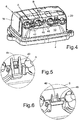
- FIG. 4 To secure the cover 6 against being lifted out of the closed position, as shown in FIG Fig. 4 is shown, on the front wall 20 of the cover 6 elastic locking tabs 42 which are latched with formed on the front wall 10 of the housing base 4, each associated locking lugs 44.
- Fig. 5 shows this detail in section A in an enlarged view. The locking tabs 42 can be easily removed manually, so without tools to remove the cover.
- Fig. 6 shows this detail in a section B in an enlarged view.
- the rear lower edge of the cover 6 formed by the respective tab extension 28, 38 forms a chamfer and thus serves as a drip edge for running spray water.
- the housing base 4 and the cover 6 are preferably designed so that the cover 6 remains when moving within the base surface of the housing base 4.
- FIGS. 7 and 8 show a controller 50 with a housing base 52 and a cover 54.
- the cover 54 is similar in construction as the cover 6 in the FIGS. 1 and 4 that is, it has a top wall 56, a rear wall 58 and two side walls 60 and an oblique front wall 62 in the present case, which rests against a front wall 64 of the housing base 52 in the closed state of the cover.
- each circular cable bushing openings 66th again on the lower edge of the front wall 62 of the cover 54 on the one hand and on the upper edge of the front wall 64 of the housing base 52 on the other hand formed recesses each circular cable bushing openings 66th
- two locking cams 68, 69 are formed in each case at a distance, when the cover 54 is pushed into associated side walls 70 of the housing base 52, which are open towards the rear, inclined obliquely downwards and forwards and narrowing Locking slots 72, 73 engage. Because of the oblique configuration of the latching slots 72, 73, the cover 56 is pushed down on the housing base 52 when advancing in the direction of the arrow 74.
- the rear lower edge 78 of the cover 54 is in turn bevelled and forms a drip edge for spray water.
- grooves 80 are formed for collecting and discharging water spray.
Description
Die Erfindung betrifft ein Gehäuse für ein Steuergerät, aufweisend eine Gehäusebasis, auf der über Kabel mit externen Aggregaten verbindbare Steuerungskomponenten montiert sind, eine haubenartige Abdeckung mit einer oberen Deckwand, einer Rückwand, zwei Seitenwänden und einer Vorderwand, an deren Unterkante Kabeldurchführungen bildende Ausnehmungen ausgebildet sind, und mit an der Gehäusebasis einerseits und der Abdeckung andererseits angeordneten Rastmitteln, die beim Aufschieben der Abdeckung auf die Gehäusebasis ineinander greifen.The invention relates to a housing for a control unit, comprising a housing base, are mounted on the cable via external assemblies connectable control components, a hood-like cover with an upper top wall, a rear wall, two side walls and a front wall, at the lower edge of which cable penetrations forming recesses are formed , And with on the housing base on the one hand and the cover on the other hand arranged latching means which engage in the sliding of the cover on the housing base.
Elektrische oder elektronische Steuergeräte enthalten in der Regel empfindliche elektrische, mechanische oder Druckmittel-Steuerungskomponenten, die vor Umgebungseinflüssen geschützt werden müssen. Insbesondere in Nutzfahrzeugen und Personenwagen sind Steuergeräte häufig an Stellen angeordnet, wo sie einer Verschmutzung, Feuchtigkeit und mechanischen Belastungen ausgesetzt sind. Die Gehäuse für derartige Steuergeräte müssen deshalb so beschaffen sein, dass sie einen ausreichenden Schutz gegen derartige Umgebungseinflüsse gewährleisten. Wegen des im Allgemeinen begrenzten Einbauraumes ist es zudem wichtig, dass zu Wartungs- und Reparaturzwecken die Steuerungskomponenten möglichst leicht zugänglich gemacht werden, so dass ein Deckel des Steuergeräts leicht und mit geringem Lösehub abnehmbar ist.Electrical or electronic control devices usually contain sensitive electrical, mechanical or pressure medium control components that must be protected from environmental influences. In particular, in commercial vehicles and passenger cars control units are often located at locations where they are exposed to pollution, moisture and mechanical stress. The housings for such control devices must therefore be such that they ensure adequate protection against such environmental influences. Because of the generally limited installation space, it is also important that for maintenance and repair purposes, the control components are made as easy as possible, so that a cover of the controller is easy and removable with a small release stroke.
Bei vielen derzeit eingesetzten Steuergeräten sind die oben genannten Anforderungen nur unvollkommen erfüllt, denn sie bieten im eingebauten Zustand nicht selten nur einen unzureichenden Schutz gegen Sprüh- und Spritzwasser, gegen Staub und Schmutz sowie gegen mechanische Belastungen, und für deren Montage beziehungsweise Demontage insbesondere der des Deckels beziehungsweise der Abdeckung des Steuergeräts ist ein großer Freiraum erforderlich.In many currently used control devices, the above requirements are met only imperfectly, because they often offer in the installed state only inadequate protection against spray and spray water, against dust and dirt and against mechanical stress, and for their assembly or disassembly in particular the Lid or the cover of the controller is a large space required.
Aus der
Vor diesem Hintergrund liegt der Erfindung die Aufgabe zugrunde, ein Gehäuse für ein Steuergerät der im Oberbegriff der Ansprüche 1 und 5 genannten Art zu schaffen, welches im eingebauten Zustand einen ausreichenden Schutz gegen Sprüh- und Spritzwasser, Staub und Schmutz sowie mechanische Belastungen bietet, wobei die Abdeckung mit einem möglichst geringen Lösehub demontierbar sein soll.Against this background, the invention has the object to provide a housing for a control device referred to in the preamble of claims 1 and 5, which provides a sufficient protection against sprayed and sprayed water, dust and dirt and mechanical loads when installed, wherein the cover should be removable with the lowest possible Lösehub.
Die Lösung der oben genannten Aufgabe ergibt sich aus den Merkmalen des Anspruchs 1 sowie des Anspruchs 5, während vorteilhafte Ausgestaltungen und Weiterbildungen der Erfindung den jeweiligen Unteransprüchen entnehmbar sind.The solution of the above-mentioned object results from the features of claim 1 and of claim 5, while advantageous embodiments and further developments of the invention the respective subclaims can be removed.
Die Erfindung betrifft demnach Steuergerät, aufweisend eine Gehäusebasis, auf der über Kabel mit externen Aggregaten verbindbare Steuerungskomponenten montiert sind, eine haubenartige Abdeckung mit einer oberen Deckwand, einer Rückwand, zwei Seitenwänden und einer Vorderwand, an deren Unterkante Kabeldurchführungen bildende Ausnehmungen ausgebildet sind, und mit an der Gehäusebasis einerseits und der Abdeckung andererseits angeordneten Rastmitteln, die beim Aufschieben der Abdeckung auf die Gehäusebasis ineinander greifen.Accordingly, the invention relates to a control unit comprising a housing base on which control components connectable via cables to external units are mounted, a hood-like cover having an upper cover wall, a rear wall, two side walls and a front wall, at the lower edge of which cable penetrations forming recesses are formed, and with on the housing base on the one hand and the cover on the other hand arranged latching means which engage in the sliding of the cover on the housing base.
Es sei an dieser Stelle bemerkt, dass die Begriffe "oben", "unten", "hinten" und "vorne" auf eine normale Lage des Steuergerätes bezogen sind, bei der die Abdeckung in einer horizontalen Ebene von hinten nach vorne auf die Gehäusebasis aufgeschoben wird.It should be noted at this point that the terms "top", "bottom", "rear" and "front" refer to a normal position of the control unit, in which the cover is pushed in a horizontal plane from back to front on the housing base becomes.
Zur Lösung der oben genannten Aufgabe ist gemäß einer ersten Ausführungsform vorgesehen, dass an der Unterkante der Rückwand der Abdeckung über deren gesamte Breite ein schräg nach unten und vorne gerichteter Laschenfortsatz angeordnet ist, der beim Aufschieben der Abdeckung auf die Gehäusebasis von hinten nach vorne in eine zugeordnete, an der Gehäusebasis ausgebildete Rinne mit einem nach vorne keilförmig zugespitzten Querschnitt eingreift, und dass im vorderen Bereich der Abdeckung und der Gehäusebasis verrastbare sowie lösbare Rastmittel vorgesehen sind, welche die Abdeckung gegen ein Abheben sowie ein Verschieben nach hinten sichern.To achieve the above object is provided according to a first embodiment, that at the lower edge of the rear wall of the cover over its entire width an obliquely downward and forward directed lug extension is arranged, the sliding of the cover on the housing base from back to front in a assigned, formed on the housing base groove engages with a wedge-shaped tapered to the front cross-section, and that in the front region of the cover and the housing base latchable and releasable locking means are provided which secure the cover against lifting and sliding backwards.
Zur Montage der Abdeckung auf der Gehäusebasis wird die Abdeckung demnach so über die Gehäusebasis geschoben, dass der Laschenfortsatz der Abdeckung in die Rinne der Gehäusebasis eingreift, wobei die Abdeckung in ihrem hinteren Bereich aufgrund der beschriebenen Ausgestaltung der Rinne nach unten an die Gehäusebasis angedrückt wird.For mounting the cover on the housing base, the cover is thus pushed over the housing base, that the tab extension of the cover engages in the channel of the housing base, wherein the cover is pressed in its rear region due to the described configuration of the channel down to the housing base.
Dass die hintere untere Kante der Abdeckung abgeschrägt ausgebildet ist, bietet den zusätzlichen Vorteil, dass sie eine Tropfkante für ablaufendes Spritzwasser bildet.The fact that the rear lower edge of the cover is beveled, has the additional advantage that it forms a drip edge for running water splashing.
Der Laschenfortsatz der Abdeckung kann gemäß einer günstigen Ausgestaltung der Erfindung zu seiner Endkante hin wulstartig verdickt ausgebildet sein und bildet so mit der am Rinnenboden gelenkpfannenartig ausgerundeten Rinne eine Art Schwenkgelenk, welches ein Abheben nur des vorderen Bereiches der Abdeckung nach oben erlaubt.According to a favorable embodiment of the invention, the lug extension of the cover can be made bead-like thickened toward its end edge, thus forming a kind of pivoting joint with the channel, which is rounded at the bottom of the channel. which allows lifting only the front portion of the cover upwards.
Bei der Montage wird die Abdeckung mit leicht nach oben abgehobenem vorderen Ende nach vorne über die Gehäusebasis geschoben, bis der Laschenfortsatz in die Rinne eingreift. Sodann wird die Abdeckung nach unten geschwenkt, wobei an der Abdeckung angeordnete Rastmittel in Rastausnehmungen eingreifen, wie nachfolgend näher beschrieben wird.When assembling, push the cover over the base of the housing with the front end slightly raised upwards until the tab extension engages the channel. Then, the cover is pivoted downward, wherein arranged on the cover locking means engage in recesses, as will be described in more detail below.
Eine diesbezügliche Ausgestaltung der Erfindung sieht vor, dass die gegen ein Verschieben der Abdeckung nach hinten sichernden Rastmittel wenigstens einen an einer Seitenwand angeordneten, nach unten ragenden Vorsprung aufweisen, welcher im montierten Zustand, also bei abgesenktem vorderen Ende der Abdeckung, in eine zugeordnete Ausnehmung an der Gehäusebasis eingreift.A related embodiment of the invention provides that against a displacement of the cover back locking locking means have at least one arranged on a side wall, downwardly projecting projection, which in the assembled state, ie at lowered front end of the cover, in an associated recess the housing base engages.
Um die Abdeckung gegen ein Abheben ihres vorderen Bereiches zu sichern, weisen die diesbezüglichen Rastmittel wenigstens eine an der Vorderwand der Abdeckung angeordnete Rastlasche auf, die im montierten Zustand der Abdeckung mit einer an der Gehäusebasis ausgebildeten Rastnase verrastbar ist, beziehungsweise umgekehrt, das heißt, die Rastlasche kann an der Gehäusebasis und die Rastnase an der Abdeckung angeordnet sein.In order to secure the cover against lifting of its front region, the relevant latching means have at least one locking tab arranged on the front wall of the cover, which can be latched in the assembled state of the cover with a detent formed on the housing base, or vice versa, that is Latching tab may be disposed on the housing base and the latching lug on the cover.
Eine zweite Ausführungsform der vorliegenden Erfindung betrifft das gleiche Gehäuse für ein Steuergerät, aufweisend eine Gehäusebasis, auf der über Kabel mit externen Aggregaten verbindbare Steuerungskomponenten montiert sind, eine haubenartige Abdeckung mit einer oberen Deckwand, einer Rückwand, zwei Seitenwänden und einer Vorderwand, an deren Unterkante Kabeldurchführungen bildende Ausnehmungen ausgebildet sind, und mit an der Gehäusebasis einerseits und der Abdeckung andererseits angeordneten Rastmitteln, die beim Aufschieben der Abdeckung auf die Gehäusebasis ineinander greifen. Zur Lösung der gleichen Aufgabe ist mit Abweichung zu der ersten Ausführungsform vorgesehen, dass an der Außenseite der Seitenwände jeweils mit Abstand hintereinander zwei Rastnocken ausgebildet sind, welche beim Aufschieben der Abdeckung auf die Gehäusebasis in zugeordnete, an Seitenstegen der Gehäusebasis ausgebildete, nach hinten offene und im Wesentlichen schräg nach unten und vorne geneigte Rastschlitze eingreifen, und dass im vorderen Bereich der Abdeckung und der Gehäusebasis verrastbare sowie lösbare Rastmittel vorgesehen sind, welche die Abdeckung gegen ein Verschieben nach hinten sichern.A second embodiment of the present invention relates to the same housing for a control unit, comprising a housing base on which control components connectable via cables to external units, a hood-like cover having an upper top wall, a rear wall, two side walls and a front wall at the lower edge thereof Cable recesses forming recesses are formed, and arranged on the housing base on the one hand and the cover on the other hand latching means which engage in the sliding of the cover on the housing base. To solve the same problem is provided with deviation from the first embodiment that on the outer side of the side walls in each case at a distance two locking cams are formed, which when pushing the cover on the housing base in associated, formed on side webs of the housing base, backward open and essentially obliquely down and Engage front inclined locking slots, and that in the front region of the cover and the housing base latchable and releasable locking means are provided, which secure the cover against displacement to the rear.
Bei dieser zweiten Ausführungsform des Steuergerätgehäuses wird mit der Aufschiebebewegung die Abdeckung wegen der beschriebenen Ausgestaltung der Rastschlitze nach unten gegen die Gehäusebasis gedrückt, so dass die Unterkanten der Rückwand und der Seitenwände auf zugeordneten Flächen der Gehäusebasis abdichtend aufliegen. Die im vorderen Bereich der Abdeckung und der Gehäusebasis angeordneten Rastmittel werden verrastet und verhindern so ein Verschieben der Abdeckung nach hinten.In this second embodiment of the control unit housing, the cover is pressed down against the housing base with the Aufschiebebewegung because of the described configuration of the locking slots, so that the lower edges of the rear wall and the side walls rest on associated surfaces of the housing base sealingly. The arranged in the front region of the cover and the housing base locking means are locked and thus prevent a displacement of the cover to the rear.
Die gegen ein Verschieben nach hinten sichernden Rastmittel umfassen gemäß einer weiteren Ausgestaltung der Erfindung wenigstens eine an einer Seitenwand der Abdeckung angeordnete Rastlasche, die im montierten Zustand der Abdeckung mit einer an der Gehäusebasis ausgebildeten Rastnase verrastbar ist, beziehungsweise umgekehrt, das heißt, die wenigstens eine Rastlasche und die wenigstens eine Rastnase können auch vertauscht angeordnet sein.The securing against a displacement to the rear latching means comprise according to a further embodiment of the invention at least one arranged on a side wall of the cover latching tab which is latched in the assembled state of the cover with a formed on the housing base locking lug, or vice versa, that is, the at least one Latching tab and the at least one locking lug can also be arranged reversed.
Gemäß einer bevorzugten Ausgestaltung der Erfindung erstreckt sich die Vorderwand der Abdeckung jeweils nach unten bis zur Höhe einer auf der Gehäusebasis stehenden Vorderwand, wobei an der Oberkante der Vorderwand der Gehäusebasis etwa teilkreisförmige Ausnehmungen ausgebildet sind, die sich mit teilkreisförmigen Ausnehmungen an der Unterkante der Vorderwand der Abdeckung zu im Wesentlichen kreisförmigen Kabeldurchführungsöffnungen ergänzen. Wie an sich bekannt ist, haben die Kabeldurchführungsöffnungen einen etwas geringeren Durchmesser als die durch diese hindurchführenden Kabel, so dass die Kabel bei der Montage der Abdeckung im Sinne einer Zugentlastung etwas eingeklemmt werden.According to a preferred embodiment of the invention, the front wall of the cover each extends down to the level of standing on the housing base front wall, wherein at the upper edge of the front wall of the housing base approximately part-circular recesses are formed, which with part-circular recesses on the lower edge of the front wall Add cover to substantially circular cable glands. As is known per se, the cable feedthrough openings have a slightly smaller diameter than the cable passing therethrough, so that the cables are clamped in the assembly of the cover in the sense of a strain relief something.
Die weiter vorne beschriebenen, an der Gehäusebasis ausgebildeten Rastnasen beziehungsweise Rastlaschen sind gemäß einer weiteren Ausgestaltung der Erfindung jeweils an der oben beschriebenen Vorderwand der Gehäusebasis ausgebildet oder angeordnet, wie anhand von Ausführungsbeispielen noch dargelegt wird.The latching lugs or latching tabs described above, formed on the housing base are each formed or arranged according to a further embodiment of the invention on the above-described front wall of the housing base, as will be explained with reference to embodiments.
Gemäß einer weiteren Ausgestaltung der Erfindung sind auf der Oberseite der Gehäusebasis jeweils entlang der Seitenwände der montierten Abdeckung sich erstreckende Rinnen zum Sammeln und Abführen von von der Abdeckung ablaufendem Spritzwasser ausgebildet.According to a further embodiment of the invention, extending grooves for collecting and discharging water running off the cover are formed on the upper side of the housing base along the side walls of the mounted cover.
Schließlich kann gemäß einer vorteilhaften Ausführungsform vorgesehen sein, dass an der Vorderwand der Abdeckung eine Führungsnase angeordnet ist, die beim Schließen der Abdeckung in eine zugeordnete, an der Vorderwand der Gehäusebasis ausgebildete Ausnehmung eingreift.Finally, it can be provided according to an advantageous embodiment, that on the front wall of the cover, a guide nose is arranged, which engages when closing the cover in an associated, formed on the front wall of the housing base recess.
Die Erfindung wird nachfolgend anhand mehrerer Ausführungsbeispiele weiter erläutert. Dazu ist der Beschreibung eine Zeichnung beigefügt. In dieser zeigt
-
Fig. 1 in einer perspektivischen Ansicht ein elektrisches Steuergerät mit einer an eine Gehäusebasis angesetzten, jedoch noch nicht geschlossenen Abdeckung, -
Fig. 2 eine Seitenansicht des elektrischen Steuergeräts gemäßFig. 1 mit geschlossener Abdeckung sowie etwa in der Mitte teilweise geschnitten zur Darstellung einer Ablaufrinne, -
Fig. 3 eine Seitenansicht des elektrischen Steuergeräts gemäßFig. 1 mit geschlossener Abdeckung sowie an einer Seite geschnitten zur Darstellung von Befestigungsmittel, -
Fig. 4 eine Ansicht ähnlich derFig. 1 , jedoch mit geschlossener Abdeckung, -
Fig. 5 und Fig. 6 jeweils Einzelheiten aus derFig. 4 , -
Fig. 7 schematisch eine Seitenansicht einer zweiten Ausführungsform eines Steuergeräts mit geschlossener Abdeckung, und -
Fig. 8 eine perspektivische Ansicht des Steuergeräts gemäßFig. 7 .
-
Fig. 1 in a perspective view of an electrical control device with a attached to a housing base, but not yet closed cover, -
Fig. 2 a side view of the electrical control device according toFig. 1 with closed cover as well as partially cut in the middle to show a gutter, -
Fig. 3 a side view of the electrical control device according toFig. 1 with closed cover and cut on one side to show fasteners, -
Fig. 4 a view similar to the oneFig. 1 , but with closed cover, -
Fig. 5 and Fig. 6 Details from eachFig. 4 . -
Fig. 7 schematically a side view of a second embodiment of a control device with closed cover, and -
Fig. 8 a perspective view of the controller according toFig. 7 ,
Das in
Die Abdeckung 6 besteht im Wesentlichen aus einer Deckwand 14, einer in
Um die Abdeckung 6 auf der Gehäusebasis 4 zu montieren, wird diese, wie in
Wie die
Wie insbesondere
Um die Abdeckung 6 gegen ein Abheben aus der geschlossenen Stellung zu sichern, sind, wie in
Um die Abdeckung 6 beim Schließen zu führen und im geschlossenen Zustand zusätzlich zu fixieren, ist an der Vorderwand 20 der Abdeckung 6 eine mit ihrem freien Ende nach unten weisende Führungsnase 46 angeordnet, die beim Schließen der Abdeckung 6 in eine zugeordnete, an der Vorderwand 10 der Gehäusebasis 4 ausgebildete Ausnehmung 48 eingreift.
Die von dem jeweiligen Laschenfortsatz 28, 38 gebildete hintere Unterkante der Abdeckung 6 bildet eine Abschrägung und dient damit als Tropfkante für ablaufendes Spritzwasser.The rear lower edge of the
Es ist erkennbar, dass der für eine Montage oder Demontage jeweils erforderliche Lösehub und auch die Verschiebestrecke äußerst gering sind, wobei die Gehäusebasis 4 und die Abdeckung 6 vorzugsweise so ausgelegt sind, dass die Abdeckung 6 beim Verschieben innerhalb der Grundfläche der Gehäusebasis 4 bleibt.It can be seen that the respectively required for a mounting or dismounting Lösehub and the displacement distance are extremely low, wherein the
Die
An der Außenseite der Seitenwände 60 sind jeweils mit Abstand hintereinander zwei Rastnocken 68, 69 ausgebildet, die beim Aufschieben der Abdeckung 54 in zugeordnete, an Seitenstegen 70 der Gehäusebasis 52 ausgebildete, nach hinten offene, im Wesentlichen schräg nach unten und vorne geneigte sowie sich verengende Rastschlitze 72, 73 eingreifen. Wegen der schrägen Ausgestaltung der Rastschlitze 72, 73 wird die Abdeckung 56 beim Vorschieben in Richtung des Pfeils 74 nach unten auf die Gehäusebasis 52 gedrückt.On the outside of the
Um eine Verschiebung der Abdeckung 56 nach hinten zu verhindern, sind an den Seitenwänden 60 der Abdeckung 56 elastische Rastlaschen 76, 77 angeordnet, welche mit an den Seitenkanten der Vorderwand 62 der Gehäusebasis 52 ausgebildeten, in der
Die hintere Unterkante 78 der Abdeckung 54 ist wiederum abgeschrägt und bildet eine Tropfkante für Spritzwasser. Auf der Oberseite der Gehäusebasis 52 entlang der Seitenwände 60 sind Rinnen 80 zum Sammeln und Abführen von Spritzwasser ausgebildet.The rear
- 22
- Steuergerätcontrol unit
- 44
- Gehäusebasishousing base
- 66
- Abdeckungcover
- 88th
- Befestigungsaugefastening eye
- 1010
-
Vorderwand der Gehäusebasis 4Front wall of the
housing base 4 - 1212
- Ausnehmung an der Vorderwand 10Recess on the front wall 10th
- 1414
-
Deckwand der Abdeckung 6Top wall of the
cover 6 - 1616
-
Rückwand der Abdeckung 6Rear wall of the
cover 6 - 1818
-
Seitenwand der Abdeckung 6Side wall of the
cover 6 - 2020
-
Vorderwand der Abdeckung 6Front wall of the
cover 6 - 2222
- Ausnehmung an der Vorderwand 20Recess on the front wall 20th
- 2424
-
Hinterkante der Abdeckung 6Trailing edge of the
cover 6 - 2626
- Pfeil, VerschieberichtungArrow, direction of shift
- 2828
-
Laschenfortsatz an der Abdeckung 6Laschenfortsatz on the
cover 6 - 3030
- Rinnegutter
- 3232
- Pfeil, VerschieberichtungArrow, direction of shift
- 3434
-
Vorsprung an der Abdeckung 6Projection on the
cover 6 - 3636
- Ausnehmung in der Gehäusebasis 4Recess in the housing base 4th
- 3838
-
Laschenfortsatz an der Abdeckung 6Laschenfortsatz on the
cover 6 - 4040
- Rinnegutter
- 4242
- Rastlaschesnap tab
- 4444
- Rastnasenlocking lugs
- 4646
- Führungsnaseguide nose
- 4848
- Ausnehmungrecess
- 5050
- Steuergerätcontrol unit
- 5252
- Gehäusebasishousing base
- 5454
- Abdeckungcover
- 5656
-
Deckwand der Abdeckung 54Top wall of the
cover 54 - 5858
-
Rückwand der Abdeckung 54Rear wall of the
cover 54 - 6060
-
Seitenwände der Abdeckung 54Side walls of the
cover 54 - 6262
-
Vorderwand der Abdeckung 54Front wall of the
cover 54 - 6464
-
Vorderwand der Gehäusebasis 52Front wall of the
housing base 52 - 6666
- KabeldurchführungsöffnungCable passage
- 6868
- Erster RastnockenFirst resting cam
- 6969
- Zweiter RastnockenSecond locking cam
- 7070
- Seitenstegside web
- 7272
- Erster RastschlitzFirst detent slot
- 7373
- Zweiter RastschlitzSecond detent slot
- 7474
- Pfeil, VerschieberichtungArrow, direction of shift
- 7676
- Erste RastlascheFirst stop tab
- 7777
- Zweite RastlascheSecond stop tab
- 7878
-
Unterkante der Abdeckung 54Lower edge of the
cover 54 - 8080
- Rinnegutter
- 8282
- Rastnaselocking lug
Claims (10)
- Housing for a control device (2), having a housing base (4) on which control components, which can be connected to external assemblies by means of cables, are mounted, a hood-like cover (6) with an upper top wall (14), a rear wall (16), two side walls (18) and a front wall (20), recesses (22) which form cable bushings (66) being formed at the lower edge of the said front wall, and having latching means which are arranged on the housing base (4) on the one hand and on the cover (6) on the other hand and interengage when the cover (6) is pushed onto the housing base (4), wherein the latchable and releasable latching means are provided in the front region of the cover (6) and of the housing base (4) and prevent the cover (6) from lifting off and moving to the rear, characterized in that a tab extension (28) which is directed obliquely downwards and forwards is arranged at the lower edge of the rear wall (16) of the cover (6) over the entire width thereof and, when the cover (6) is pushed onto the housing base (4), engages from the rear to the front into an associated channel (30) which is formed on the housing base (4) and has a cross section which is tapered in the manner of a wedge towards the front.
- Housing according to Claim 1, characterized in that the tab extension (38) of the cover (6) is thickened in the manner of a bead in the direction of its end edge and the channel (40) is rounded in the manner of a socket at the channel base.
- Housing according to Claim 1 or 2, characterized in that the latching means which prevent movement of the cover (6) to the rear have at least one downwardly protruding projection (34) which is arranged on a side wall (18) and, in the mounted state of the cover (6), engages into an associated recess (36) on the housing base (4).
- Housing according to one of Claims 1 to 3, characterized in that the latching means which prevent the cover (6) from lifting off have at least one latching tab (42) which is arranged on the front wall (10) of the cover (6) and, in the mounted state of the cover (6), can latch with a latching lug (44) which is formed on the housing base (4), or vice versa.
- Housing for a control device (2) having a housing base (4) on which control components, which can be connected to external assemblies by means of cables, are mounted, a hood-like cover (6) with an upper top wall (14), a rear wall (16), two side walls (18) and a front wall (20), recesses (22) which form cable bushings (66) being formed at the lower edge of the said front wall, and having latching means which are arranged on the housing base (4) on the one hand and on the cover (6) on the other hand and interengage when the cover (6) is pushed onto the housing base (4), wherein the latchable and releasable latching means are provided in the front region of the cover (6) and of the housing base (4) and prevent the cover (6) from lifting off and moving to the rear, characterized in that two latching cams (68, 69) are formed in each case at a distance one behind the other on the outer face of the side walls (60) and, when the cover (54) is pushed onto the housing base (52), engage into associated latching slots (72, 73) which are formed on side webs (70) of the housing base (52), are open to the rear and are inclined substantially obliquely downwards and forwards.
- Housing according to Claim 5, characterized in that the latching means which prevent movement to the rear comprise at least one latching tab (76, 77) which is arranged on a side wall (60) of the cover (54) and, in the mounted state of the cover (54), can be latched to a latching lug which is formed on the housing base (52), and vice versa.
- Housing according to one of Claims 1 to 6, characterized in that the front wall (20) of the cover (6) extends downwards down to a height of a front wall (10) standing on the housing base (4), and in that approximately semicircular recesses (12) are formed on the upper edge of the front wall (10) of the housing base (4) and are complemented by approximately semicircular recesses (22) on the lower edge of the front wall (20) of the cover (6) to form substantially circular cable bushing openings.
- Housing according to Claim 4 or 5 in conjunction with Claim 7, characterized in that the latching lug (44) or latching tab (42) which is formed on the housing base (4) is formed or arranged on the front wall (10) of the housing base (4) in each case.
- Housing according to one of Claims 1 to 8, characterized in that channels (80), which each extend along the side walls (60) of the mounted cover (54), for collecting and discharging splashing water running off from the cover are formed on the top side of the housing base (52).
- Housing according to one of Claims 1 to 9, characterized in that a guide lug (46) is arranged on the front wall (20) of the cover (6) and, when the cover (6) is closed, engages into an associated recess (48) which is formed on the front wall (10) of the housing base (4).
Applications Claiming Priority (1)
| Application Number | Priority Date | Filing Date | Title |
|---|---|---|---|
| DE102013020255.8A DE102013020255A1 (en) | 2013-11-29 | 2013-11-29 | Housing for a control unit |
Publications (2)
| Publication Number | Publication Date |
|---|---|
| EP2879472A1 EP2879472A1 (en) | 2015-06-03 |
| EP2879472B1 true EP2879472B1 (en) | 2018-01-17 |
Family
ID=51795478
Family Applications (1)
| Application Number | Title | Priority Date | Filing Date |
|---|---|---|---|
| EP14003597.3A Active EP2879472B1 (en) | 2013-11-29 | 2014-10-22 | Housing for a control device |
Country Status (2)
| Country | Link |
|---|---|
| EP (1) | EP2879472B1 (en) |
| DE (1) | DE102013020255A1 (en) |
Families Citing this family (2)
| Publication number | Priority date | Publication date | Assignee | Title |
|---|---|---|---|---|
| JP6137737B2 (en) * | 2015-09-11 | 2017-05-31 | 株式会社安川電機 | Electrical equipment casing and power converter |
| CN114727897B (en) * | 2019-11-15 | 2023-12-26 | 利纳克有限公司 | control unit |
Family Cites Families (6)
| Publication number | Priority date | Publication date | Assignee | Title |
|---|---|---|---|---|
| US4126224A (en) * | 1977-11-03 | 1978-11-21 | Laauwe Robert H | Moisture-proof and child-resistant pill box |
| CH659164A5 (en) * | 1983-05-16 | 1986-12-31 | Gfeller Ag | Housing to receive an electronic device |
| US5497036A (en) * | 1994-10-21 | 1996-03-05 | Harley-Davidson | Motorcycle terminal box assembly |
| WO1996028355A1 (en) * | 1995-03-10 | 1996-09-19 | Ericsson Raynet | Environmental enclosure and method of sealing same |
| DE19528252B4 (en) | 1995-08-01 | 2009-06-25 | Knorr-Bremse Systeme für Nutzfahrzeuge GmbH | Aggregate for a vehicle brake system |
| DE19545011A1 (en) * | 1995-10-05 | 1997-04-10 | Teves Gmbh Alfred | Valve block for motor vehicle pneumatic or hydraulic brake system control device |
-
2013
- 2013-11-29 DE DE102013020255.8A patent/DE102013020255A1/en not_active Withdrawn
-
2014
- 2014-10-22 EP EP14003597.3A patent/EP2879472B1/en active Active
Non-Patent Citations (1)
| Title |
|---|
| None * |
Also Published As
| Publication number | Publication date |
|---|---|
| DE102013020255A1 (en) | 2015-06-03 |
| EP2879472A1 (en) | 2015-06-03 |
Similar Documents
| Publication | Publication Date | Title |
|---|---|---|
| EP2084339B1 (en) | Grating | |
| EP2339701B1 (en) | Circuit board connector with locking device | |
| DE102014101405A1 (en) | Floor assembly for the frame of a cabinet | |
| DE202012104530U1 (en) | Set of panels with clip | |
| EP3378129A1 (en) | Holding frame for holding plug connector modules | |
| WO2002071566A2 (en) | Cable link | |
| DE102018128042A1 (en) | Set of connector and retaining element and connector and retaining element for this purpose | |
| EP2879472B1 (en) | Housing for a control device | |
| DE202010010424U1 (en) | Wall feed-through terminal for electrical conductors | |
| DE102008034113A1 (en) | Electric connecting device i.e. plug-type connecting device, for transmitting electric power for controlling and operating servomotor, has latching device comprising latching unit arranged inclined to base surface of shielding plate | |
| DE102010017424A1 (en) | Device for locking a cover | |
| EP2114200B1 (en) | Control desk | |
| EP2872712B1 (en) | Construction kit for producing coverings | |
| DE202008006250U1 (en) | connection | |
| DE102004013010B3 (en) | Device for holding elongated objects | |
| EP2418746A2 (en) | Device socket for installation devices | |
| DE3206526A1 (en) | Attachment device for a mirror | |
| DE202013100083U1 (en) | One-piece plastic molded part with a flap that snaps into a closed position without play | |
| DE102012217815A1 (en) | Duct for installation of electrical lines, has manhole cover whose base portion is provided with locking unit for attaching to metallic base portion in latched state, while cover panel does not attaches to metallic base portion | |
| DE69738519T2 (en) | Fixing device for household electrical appliances, for fastening of an electrical component | |
| DE102019104723B4 (en) | Control cabinet arrangement with a control cabinet and at least one power strip | |
| DE3441377A1 (en) | Cable duct for holding installation lines | |
| EP0606850A2 (en) | Battery with detachable cover plate covering the terminals | |
| EP3558058B1 (en) | Piece of furniture comprising a cable feedthrough and method for forming a cable feedthrough | |
| DE102014217557A1 (en) | Adapter for a windshield wiper, wiper element and wiper system |
Legal Events
| Date | Code | Title | Description |
|---|---|---|---|
| PUAI | Public reference made under article 153(3) epc to a published international application that has entered the european phase |
Free format text: ORIGINAL CODE: 0009012 |
|
| 17P | Request for examination filed |
Effective date: 20141022 |
|
| AK | Designated contracting states |
Kind code of ref document: A1 Designated state(s): AL AT BE BG CH CY CZ DE DK EE ES FI FR GB GR HR HU IE IS IT LI LT LU LV MC MK MT NL NO PL PT RO RS SE SI SK SM TR |
|
| AX | Request for extension of the european patent |
Extension state: BA ME |
|
| R17P | Request for examination filed (corrected) |
Effective date: 20151203 |
|
| RBV | Designated contracting states (corrected) |
Designated state(s): AL AT BE BG CH CY CZ DE DK EE ES FI FR GB GR HR HU IE IS IT LI LT LU LV MC MK MT NL NO PL PT RO RS SE SI SK SM TR |
|
| GRAP | Despatch of communication of intention to grant a patent |
Free format text: ORIGINAL CODE: EPIDOSNIGR1 |
|
| INTG | Intention to grant announced |
Effective date: 20170925 |
|
| GRAS | Grant fee paid |
Free format text: ORIGINAL CODE: EPIDOSNIGR3 |
|
| GRAA | (expected) grant |
Free format text: ORIGINAL CODE: 0009210 |
|
| AK | Designated contracting states |
Kind code of ref document: B1 Designated state(s): AL AT BE BG CH CY CZ DE DK EE ES FI FR GB GR HR HU IE IS IT LI LT LU LV MC MK MT NL NO PL PT RO RS SE SI SK SM TR |
|
| REG | Reference to a national code |
Ref country code: GB Ref legal event code: FG4D Free format text: NOT ENGLISH |
|
| REG | Reference to a national code |
Ref country code: CH Ref legal event code: EP |
|
| REG | Reference to a national code |
Ref country code: IE Ref legal event code: FG4D Free format text: LANGUAGE OF EP DOCUMENT: GERMAN |
|
| REG | Reference to a national code |
Ref country code: AT Ref legal event code: REF Ref document number: 965238 Country of ref document: AT Kind code of ref document: T Effective date: 20180215 |
|
| REG | Reference to a national code |
Ref country code: DE Ref legal event code: R096 Ref document number: 502014006967 Country of ref document: DE |
|
| REG | Reference to a national code |
Ref country code: SE Ref legal event code: TRGR |
|
| REG | Reference to a national code |
Ref country code: NL Ref legal event code: MP Effective date: 20180117 |
|
| REG | Reference to a national code |
Ref country code: LT Ref legal event code: MG4D |
|
| PG25 | Lapsed in a contracting state [announced via postgrant information from national office to epo] |
Ref country code: NL Free format text: LAPSE BECAUSE OF FAILURE TO SUBMIT A TRANSLATION OF THE DESCRIPTION OR TO PAY THE FEE WITHIN THE PRESCRIBED TIME-LIMIT Effective date: 20180117 |
|
| PG25 | Lapsed in a contracting state [announced via postgrant information from national office to epo] |
Ref country code: LT Free format text: LAPSE BECAUSE OF FAILURE TO SUBMIT A TRANSLATION OF THE DESCRIPTION OR TO PAY THE FEE WITHIN THE PRESCRIBED TIME-LIMIT Effective date: 20180117 Ref country code: CY Free format text: LAPSE BECAUSE OF FAILURE TO SUBMIT A TRANSLATION OF THE DESCRIPTION OR TO PAY THE FEE WITHIN THE PRESCRIBED TIME-LIMIT Effective date: 20180117 Ref country code: FI Free format text: LAPSE BECAUSE OF FAILURE TO SUBMIT A TRANSLATION OF THE DESCRIPTION OR TO PAY THE FEE WITHIN THE PRESCRIBED TIME-LIMIT Effective date: 20180117 Ref country code: NO Free format text: LAPSE BECAUSE OF FAILURE TO SUBMIT A TRANSLATION OF THE DESCRIPTION OR TO PAY THE FEE WITHIN THE PRESCRIBED TIME-LIMIT Effective date: 20180417 Ref country code: ES Free format text: LAPSE BECAUSE OF FAILURE TO SUBMIT A TRANSLATION OF THE DESCRIPTION OR TO PAY THE FEE WITHIN THE PRESCRIBED TIME-LIMIT Effective date: 20180117 Ref country code: HR Free format text: LAPSE BECAUSE OF FAILURE TO SUBMIT A TRANSLATION OF THE DESCRIPTION OR TO PAY THE FEE WITHIN THE PRESCRIBED TIME-LIMIT Effective date: 20180117 |
|
| PG25 | Lapsed in a contracting state [announced via postgrant information from national office to epo] |
Ref country code: RS Free format text: LAPSE BECAUSE OF FAILURE TO SUBMIT A TRANSLATION OF THE DESCRIPTION OR TO PAY THE FEE WITHIN THE PRESCRIBED TIME-LIMIT Effective date: 20180117 Ref country code: LV Free format text: LAPSE BECAUSE OF FAILURE TO SUBMIT A TRANSLATION OF THE DESCRIPTION OR TO PAY THE FEE WITHIN THE PRESCRIBED TIME-LIMIT Effective date: 20180117 Ref country code: GR Free format text: LAPSE BECAUSE OF FAILURE TO SUBMIT A TRANSLATION OF THE DESCRIPTION OR TO PAY THE FEE WITHIN THE PRESCRIBED TIME-LIMIT Effective date: 20180418 Ref country code: PL Free format text: LAPSE BECAUSE OF FAILURE TO SUBMIT A TRANSLATION OF THE DESCRIPTION OR TO PAY THE FEE WITHIN THE PRESCRIBED TIME-LIMIT Effective date: 20180117 Ref country code: IS Free format text: LAPSE BECAUSE OF FAILURE TO SUBMIT A TRANSLATION OF THE DESCRIPTION OR TO PAY THE FEE WITHIN THE PRESCRIBED TIME-LIMIT Effective date: 20180517 Ref country code: BG Free format text: LAPSE BECAUSE OF FAILURE TO SUBMIT A TRANSLATION OF THE DESCRIPTION OR TO PAY THE FEE WITHIN THE PRESCRIBED TIME-LIMIT Effective date: 20180417 |
|
| PG25 | Lapsed in a contracting state [announced via postgrant information from national office to epo] |
Ref country code: MT Free format text: LAPSE BECAUSE OF FAILURE TO SUBMIT A TRANSLATION OF THE DESCRIPTION OR TO PAY THE FEE WITHIN THE PRESCRIBED TIME-LIMIT Effective date: 20180117 |
|
| REG | Reference to a national code |
Ref country code: DE Ref legal event code: R097 Ref document number: 502014006967 Country of ref document: DE |
|
| PG25 | Lapsed in a contracting state [announced via postgrant information from national office to epo] |
Ref country code: AL Free format text: LAPSE BECAUSE OF FAILURE TO SUBMIT A TRANSLATION OF THE DESCRIPTION OR TO PAY THE FEE WITHIN THE PRESCRIBED TIME-LIMIT Effective date: 20180117 Ref country code: IT Free format text: LAPSE BECAUSE OF FAILURE TO SUBMIT A TRANSLATION OF THE DESCRIPTION OR TO PAY THE FEE WITHIN THE PRESCRIBED TIME-LIMIT Effective date: 20180117 Ref country code: EE Free format text: LAPSE BECAUSE OF FAILURE TO SUBMIT A TRANSLATION OF THE DESCRIPTION OR TO PAY THE FEE WITHIN THE PRESCRIBED TIME-LIMIT Effective date: 20180117 Ref country code: RO Free format text: LAPSE BECAUSE OF FAILURE TO SUBMIT A TRANSLATION OF THE DESCRIPTION OR TO PAY THE FEE WITHIN THE PRESCRIBED TIME-LIMIT Effective date: 20180117 |
|
| PLBE | No opposition filed within time limit |
Free format text: ORIGINAL CODE: 0009261 |
|
| STAA | Information on the status of an ep patent application or granted ep patent |
Free format text: STATUS: NO OPPOSITION FILED WITHIN TIME LIMIT |
|
| PG25 | Lapsed in a contracting state [announced via postgrant information from national office to epo] |
Ref country code: SK Free format text: LAPSE BECAUSE OF FAILURE TO SUBMIT A TRANSLATION OF THE DESCRIPTION OR TO PAY THE FEE WITHIN THE PRESCRIBED TIME-LIMIT Effective date: 20180117 Ref country code: CZ Free format text: LAPSE BECAUSE OF FAILURE TO SUBMIT A TRANSLATION OF THE DESCRIPTION OR TO PAY THE FEE WITHIN THE PRESCRIBED TIME-LIMIT Effective date: 20180117 Ref country code: DK Free format text: LAPSE BECAUSE OF FAILURE TO SUBMIT A TRANSLATION OF THE DESCRIPTION OR TO PAY THE FEE WITHIN THE PRESCRIBED TIME-LIMIT Effective date: 20180117 Ref country code: SM Free format text: LAPSE BECAUSE OF FAILURE TO SUBMIT A TRANSLATION OF THE DESCRIPTION OR TO PAY THE FEE WITHIN THE PRESCRIBED TIME-LIMIT Effective date: 20180117 |
|
| 26N | No opposition filed |
Effective date: 20181018 |
|
| PG25 | Lapsed in a contracting state [announced via postgrant information from national office to epo] |
Ref country code: SI Free format text: LAPSE BECAUSE OF FAILURE TO SUBMIT A TRANSLATION OF THE DESCRIPTION OR TO PAY THE FEE WITHIN THE PRESCRIBED TIME-LIMIT Effective date: 20180117 |
|
| REG | Reference to a national code |
Ref country code: CH Ref legal event code: PL |
|
| GBPC | Gb: european patent ceased through non-payment of renewal fee |
Effective date: 20181022 |
|
| REG | Reference to a national code |
Ref country code: BE Ref legal event code: MM Effective date: 20181031 |
|
| PG25 | Lapsed in a contracting state [announced via postgrant information from national office to epo] |
Ref country code: MC Free format text: LAPSE BECAUSE OF FAILURE TO SUBMIT A TRANSLATION OF THE DESCRIPTION OR TO PAY THE FEE WITHIN THE PRESCRIBED TIME-LIMIT Effective date: 20180117 Ref country code: LU Free format text: LAPSE BECAUSE OF NON-PAYMENT OF DUE FEES Effective date: 20181022 |
|
| REG | Reference to a national code |
Ref country code: IE Ref legal event code: MM4A |
|
| PG25 | Lapsed in a contracting state [announced via postgrant information from national office to epo] |
Ref country code: FR Free format text: LAPSE BECAUSE OF NON-PAYMENT OF DUE FEES Effective date: 20181031 Ref country code: CH Free format text: LAPSE BECAUSE OF NON-PAYMENT OF DUE FEES Effective date: 20181031 Ref country code: LI Free format text: LAPSE BECAUSE OF NON-PAYMENT OF DUE FEES Effective date: 20181031 Ref country code: BE Free format text: LAPSE BECAUSE OF NON-PAYMENT OF DUE FEES Effective date: 20181031 |
|
| PG25 | Lapsed in a contracting state [announced via postgrant information from national office to epo] |
Ref country code: IE Free format text: LAPSE BECAUSE OF NON-PAYMENT OF DUE FEES Effective date: 20181022 Ref country code: GB Free format text: LAPSE BECAUSE OF NON-PAYMENT OF DUE FEES Effective date: 20181022 |
|
| PG25 | Lapsed in a contracting state [announced via postgrant information from national office to epo] |
Ref country code: PT Free format text: LAPSE BECAUSE OF FAILURE TO SUBMIT A TRANSLATION OF THE DESCRIPTION OR TO PAY THE FEE WITHIN THE PRESCRIBED TIME-LIMIT Effective date: 20180117 |
|
| PG25 | Lapsed in a contracting state [announced via postgrant information from national office to epo] |
Ref country code: MK Free format text: LAPSE BECAUSE OF NON-PAYMENT OF DUE FEES Effective date: 20180117 Ref country code: HU Free format text: LAPSE BECAUSE OF FAILURE TO SUBMIT A TRANSLATION OF THE DESCRIPTION OR TO PAY THE FEE WITHIN THE PRESCRIBED TIME-LIMIT; INVALID AB INITIO Effective date: 20141022 |
|
| REG | Reference to a national code |
Ref country code: AT Ref legal event code: MM01 Ref document number: 965238 Country of ref document: AT Kind code of ref document: T Effective date: 20191022 |
|
| PG25 | Lapsed in a contracting state [announced via postgrant information from national office to epo] |
Ref country code: AT Free format text: LAPSE BECAUSE OF NON-PAYMENT OF DUE FEES Effective date: 20191022 |
|
| REG | Reference to a national code |
Ref country code: DE Ref legal event code: R081 Ref document number: 502014006967 Country of ref document: DE Owner name: ZF CV SYSTEMS EUROPE BV, BE Free format text: FORMER OWNER: WABCO GMBH, 30453 HANNOVER, DE Ref country code: DE Ref legal event code: R081 Ref document number: 502014006967 Country of ref document: DE Owner name: ZF CV SYSTEMS HANNOVER GMBH, DE Free format text: FORMER OWNER: WABCO GMBH, 30453 HANNOVER, DE |
|
| REG | Reference to a national code |
Ref country code: DE Ref legal event code: R081 Ref document number: 502014006967 Country of ref document: DE Owner name: ZF CV SYSTEMS EUROPE BV, BE Free format text: FORMER OWNER: ZF CV SYSTEMS HANNOVER GMBH, 30453 HANNOVER, DE |
|
| P01 | Opt-out of the competence of the unified patent court (upc) registered |
Effective date: 20230528 |
|
| PGFP | Annual fee paid to national office [announced via postgrant information from national office to epo] |
Ref country code: SE Payment date: 20230912 Year of fee payment: 10 |
|
| PGFP | Annual fee paid to national office [announced via postgrant information from national office to epo] |
Ref country code: TR Payment date: 20231019 Year of fee payment: 10 Ref country code: DE Payment date: 20230830 Year of fee payment: 10 |