EP0606850A2 - Battery with detachable cover plate covering the terminals - Google Patents
Battery with detachable cover plate covering the terminals Download PDFInfo
- Publication number
- EP0606850A2 EP0606850A2 EP94100126A EP94100126A EP0606850A2 EP 0606850 A2 EP0606850 A2 EP 0606850A2 EP 94100126 A EP94100126 A EP 94100126A EP 94100126 A EP94100126 A EP 94100126A EP 0606850 A2 EP0606850 A2 EP 0606850A2
- Authority
- EP
- European Patent Office
- Prior art keywords
- cover
- recess
- accumulator according
- cover plate
- projection
- Prior art date
- Legal status (The legal status is an assumption and is not a legal conclusion. Google has not performed a legal analysis and makes no representation as to the accuracy of the status listed.)
- Granted
Links
Images


Classifications
-
- H—ELECTRICITY
- H01—ELECTRIC ELEMENTS
- H01R—ELECTRICALLY-CONDUCTIVE CONNECTIONS; STRUCTURAL ASSOCIATIONS OF A PLURALITY OF MUTUALLY-INSULATED ELECTRICAL CONNECTING ELEMENTS; COUPLING DEVICES; CURRENT COLLECTORS
- H01R11/00—Individual connecting elements providing two or more spaced connecting locations for conductive members which are, or may be, thereby interconnected, e.g. end pieces for wires or cables supported by the wire or cable and having means for facilitating electrical connection to some other wire, terminal, or conductive member, blocks of binding posts
- H01R11/11—End pieces or tapping pieces for wires, supported by the wire and for facilitating electrical connection to some other wire, terminal or conductive member
- H01R11/28—End pieces consisting of a ferrule or sleeve
- H01R11/281—End pieces consisting of a ferrule or sleeve for connections to batteries
- H01R11/284—End pieces consisting of a ferrule or sleeve for connections to batteries comprising means for preventing corrosion, e.g. covers, enclosures filled with gel
-
- Y—GENERAL TAGGING OF NEW TECHNOLOGICAL DEVELOPMENTS; GENERAL TAGGING OF CROSS-SECTIONAL TECHNOLOGIES SPANNING OVER SEVERAL SECTIONS OF THE IPC; TECHNICAL SUBJECTS COVERED BY FORMER USPC CROSS-REFERENCE ART COLLECTIONS [XRACs] AND DIGESTS
- Y02—TECHNOLOGIES OR APPLICATIONS FOR MITIGATION OR ADAPTATION AGAINST CLIMATE CHANGE
- Y02E—REDUCTION OF GREENHOUSE GAS [GHG] EMISSIONS, RELATED TO ENERGY GENERATION, TRANSMISSION OR DISTRIBUTION
- Y02E60/00—Enabling technologies; Technologies with a potential or indirect contribution to GHG emissions mitigation
- Y02E60/10—Energy storage using batteries
Definitions
- the invention relates to an accumulator with at least one metal pole arranged in a corner region of the cover according to the preamble of patent claim 1.
- End pole covers of conventional design are fastened by means of a snap hook which engages under the lower edge of a circumferential cover apron provided on the cover. If the undercut between the cover apron and the battery housing underneath is too small, the end pole cap is not adequately held.
- Another disadvantage of the known accumulator is that the external dimensions of the battery are changed by the gripping of the snap hook over the outer circumference of the cover apron, which makes it difficult to release the snap hook in narrow installation conditions, such as the combination of several individual batteries to form battery blocks.
- a further disadvantage of the known end pole caps is that the snap hook stands in the way of frequently changing installation situations of the cable connector. For the same reason, the feeding of several of the generally very thick cables to a pole covered with the known cover cap is problematic, if not impossible.
- the aim of the invention is to provide an accumulator of the type mentioned, the pole cover of which neither changes the lateral external dimensions of the accumulator and in particular enables the universal connection of cables without the quality of the holder of the cover cap on the cover of the accumulator and its manipulability be affected.
- the latching means are located above the bottom surface of the depression, so that the part of the cover underneath, in particular the cover apron, is not required for fastening the cover plate. It is particularly advantageous that the lateral dimensions of the battery are not affected by the cover cap.
- the cover plates are held according to claim 3 in the lateral direction.
- the arrangement of the latching projection causing the holder upwards is advantageous.
- a first practical embodiment is characterized by claims 8, 9.
- a further advantageous embodiment is characterized in claims 12 to 15.
- the invention is used with particular advantage in the case of an accumulator according to claim 16, because the measures according to the invention mean that the distance between the lid surface and the lower edge of the lid apron is no longer critical.
- Preferred embodiments of the cover plate can be found in claim 20.
- the invention thus creates an end pole cover cap attachment which is only arranged above the circumferential cover apron, as a result of which the prescribed dimensions of the battery are not impaired and the cover plate can be released even in confined spaces.
- cables can also be routed to the pole from both sides of the corner and from the corner itself. It can also be easily brought several cables to the pole without this being hindered by the cover plate.
- a battery housing 24 which is only partially shown has a cover 13 which is provided on its underside with a cover apron 33 which runs all around and projects laterally beyond the housing 24. Above the cover apron 33, the cover 13 jumps back a little at 38 and then forms vertical side walls, of which only the end parts 31, 32 extending up to corners 35, 39 are shown in FIG. 1.
- the cover In the region of a corner 19 of the cover apron 33 or 40 of the housing 24, the cover has a depression 12 of rectangular or square horizontal cross section, the bottom surface 14 of which corresponds to the upper surface 38 of the Lid apron 33 is flush.
- the recess 12 is open to the outside and bounded inwards by side walls 16, 17 arranged at right angles to one another and vertically, and closed at the bottom by a bottom surface 14.
- retaining pins 20 are provided in a dashed edge strip 22 of the cover plate 18, which comes into contact with the cover surface 15 after the cover plate 18 has been placed on the cover 13 according to FIG. 1.
- An edge strip 23 of the cover plate 18 provided at right angles to the edge strip 22 comes to rest when it is placed on the cover 13 on a narrow strip of the cover surface 15 immediately next to the upper end of the side wall 16.
- a projection 34 designed as a spring web extends from the lower surface of the cover plate and is designed in the manner of a leaf spring, the plane of which is parallel to the plane of the side wall 16 runs.
- a latching projection 29 which extends towards the side wall 16 and which, when the cover plate 18 is placed on the cover 13 according to FIG. 1, can snap into a complementary latching recess 30 provided in the side wall 16.
- the cover plate 18 is divided by a hinge 42 into two parts 18 ', 18' ', one 18' of which carries the projection 34 and the other 18 '' of the holding pins 20.
- the corner 18 ′′ ′′ of the cover plate 18 lying above the corners 19, 40 of the cover or housing is rounded.
- the cover plate 18 is assembled as follows: After the cable connectors (not shown) are attached to the pole 11, the retaining pins 20 are first inserted into the associated holes 21, and the part 18 'of the cover plate 18 which bears the projection 34 can be folded up a little around the hinge 42. As soon as the part 18 ′′ with the edge strip 22 completely rests on the lid surface 15, the part 18 ′ of the cover plate 18 that bears the projection 34 is folded down, the projection 34 initially sliding somewhat away from the side wall 16 when the latching projection 29 slides along Side wall 16 is resiliently bent away until finally the locking projection 29 snaps into the locking recess 30, whereupon the cover plate 18 is finally fixed.
- the ball-shaped design of the locking projection 29 and the locking recess 30 ensure that a disengagement by lifting the cover plate 18 is possible.
- connection between the cable and the pole 11 can be made with the cover plate 18 removed or with the part 18 'only folded up.
- the projection 34 'designed as a spring bar is in the corner region 18' 'facing away from the edge strip 22 and facing the side wall end part 31. 'arranged the cover plate 18.
- the projection 34 ' is again designed in the manner of a leaf spring, but the plane of the projection 34' runs parallel to the side wall end part 31 or perpendicular to the side wall 16, so that the locking projection 25, which cooperates with a locking recess 26 provided in the region of the corner 35 , is resiliently bendable away from the side wall 31.
- the latching projection 29 and the projection 34 ' are completely accommodated in the region of the depression 12, in the embodiment according to FIGS. 3 and 4 the projection 34' stands over the side wall 31 by its relatively small thickness in front.
- the thickness of the projection 34 ' is, however, so small that lateral protrusion beyond the cover apron 33 is avoided.
- the locking projection 25 and the locking recess 26 can easily be formed so deep that a secure locking connection is created.
- the locking recess 28 can also be realized in that the side wall part 31 in the upper region into the recess 12 is extended, whereby there is a latching web 36, below which the latching recess 28 is formed. 6 with a cover plate 18 attached according to FIG. 6, a locking projection 27 is provided, which is provided on a leaf spring-like projection 34 ', which is similar to that in FIG. 4, that is to say springy away from the side wall end part 31.
- the locking web 36 could also be undercut by a projection which is formed on a spring web 34, as shown in FIG. 2.
- the projection 34 'and the locking projection 27 are so narrow in FIG. 6 that there is a correspondence with the width of the locking recess 28.
- the projection 34 'and the latching projection 27 are offset somewhat to the corner 18' ''. In this way, on the one hand the edge strip 23 can rest securely on the cover surface 15 and at the same time the spring bar 34 'with the locking projection 27 can work properly with the locking recess 28.
- the step formed by the offset of the projection 34 'with respect to the edge strip 23 is designated 43.
Abstract
Description
Die Erfindung betrifft einen Akkumulator mit wenigstens einem in einem Eckbereich des Deckels angeordneten Metallpol nach dem Oberbegriff des Patentanspruchs 1.The invention relates to an accumulator with at least one metal pole arranged in a corner region of the cover according to the preamble of patent claim 1.
Endpolabdeckungen herkömmlicher Bauweise (DIN 72.311 - Teil 17, September 1976, Seiten 1, 2) sind mittels eines Schnapphakens befestigt, der unter den unteren Rand einer am Deckel vorgesehenen umlaufenden Deckelschürze greift. Bei zu geringem Hinterschnitt zwischen Deckelschürze und dem darunter befindlichen Akkumulatorgehäuse ist die Halterung der Endpolkappe unzureichend. Nachteilig an dem bekannten Akkumulator ist weiter, daß durch das Übergreifen des Schnapphakens über den Außenumfang der Deckelschürze die Außenabmessungen der Batterie verändert werden, was bei engen Einbauverhältnissen, wie dem Zusammenschluß mehrerer Einzelakkumulatoren zu Batterieblöcken das Lösen des Schnapphakens erschwert. Weiter erweist sich bei den bekannten Endpolkappen als nachteilig, daß bei häufig wechselnden Einbausituationen des Kabelverbinders der Schnapphaken im Wege steht. Aus dem gleichen Grund ist auch die Zuführung mehrerer der im allgemeinen sehr dicken Kabel zu einem mit der bekannten Abdeckkappe abgedeckten Pol problematisch, wenn nicht gar unmöglich.End pole covers of conventional design (DIN 72.311 -
Das Ziel der Erfindung besteht darin, einen Akkumulator der eingangs genannten Gattung zu schaffen, dessen Polabdeckkappe weder die seitlichen Außenabmessungen des Akkumulators nicht verändert und insbesondere den universellen Anschluß von Kabeln ermöglicht, ohne daß die Güte der Halterung der Abdeckkappe am Deckel des Akkumulators und seine Manipulierbarkeit beeinträchtigt werden.The aim of the invention is to provide an accumulator of the type mentioned, the pole cover of which neither changes the lateral external dimensions of the accumulator and in particular enables the universal connection of cables without the quality of the holder of the cover cap on the cover of the accumulator and its manipulability be affected.
Zur Lösung dieser Aufgabe sind die Merkmale des kennzeichnenden Teils des Anspruches 1 vorgesehen.To achieve this object, the features of the characterizing part of claim 1 are provided.
Der Erfindungsgedanke ist also darin zu sehen, daß sich die Rastmittel oberhalb der Bodenfläche der Vertiefung befinden, so daß der darunter befindliche Teil des Deckels, insbesondere die Deckelschürze für die Befestigung der Deckplatte nicht benötigt wird. Besonders vorteilhaft ist dabei, daß die seitlichen Abmessungen des Akkumulators durch die Abdeckkappe nicht beeinflußt werden.The idea of the invention is therefore to be seen in the fact that the latching means are located above the bottom surface of the depression, so that the part of the cover underneath, in particular the cover apron, is not required for fastening the cover plate. It is particularly advantageous that the lateral dimensions of the battery are not affected by the cover cap.
Vorteilhafte Weiterbildungen der Erfindung sind durch die Ansprüche 2 bis 5 gekennzeichnet.Advantageous developments of the invention are characterized by claims 2 to 5.
Im allgemeinen werden die Abdeckplatten gemäß Anspruch 3 in seitlicher Richtung festgehalten. In diesem Fall ist die Anordnung des die Halterung nach oben bewirkenden Rastvorsprunges nach Anspruch 7 vorteilhaft.In general, the cover plates are held according to claim 3 in the lateral direction. In this case, the arrangement of the latching projection causing the holder upwards is advantageous.
Eine erste praktische Ausführungsform ist durch die Ansprüche 8, 9 gekennzeichnet.A first practical embodiment is characterized by claims 8, 9.
Eine besonders gute Halterung der Abdeckkappe wird auch durch die Ausführungsform nach den Ansprüchen 10, 11 erzielt.A particularly good retention of the cover cap is also achieved by the embodiment according to
Eine weitere vorteilhafte Ausführungsform ist in den Ansprüchen 12 bis 15 gekennzeichnet.A further advantageous embodiment is characterized in
Mit besonderem Vorteil wird die Erfindung bei einem Akkumulator nach Anspruch 16 angewendet, weil durch die erfindungsgemäßen Maßnahmen der Abstand der Deckeloberfläche von dem unteren Rand der Deckelschürze nicht mehr kritisch ist.The invention is used with particular advantage in the case of an accumulator according to
Besonders zweckmäßig ist die zweiteilige Ausbildung der Abdeckplatte nach den Ansprüchen 17 bis 19, weil hierdurch ihre Montage und Demontage erleichtert ist.The two-part design of the cover plate according to
Bevorzugte Ausbildungen der Abdeckplatte entnimmt man Anspruch 20.Preferred embodiments of the cover plate can be found in
Die Erfindung schafft somit eine Endpolabdeckkappenbefestigung, die lediglich oberhalb der umlaufenden Deckelschürze angeordnet ist, wodurch die vorgeschriebenen Abmessungen des Akkumulators nicht beeinträchtigt werden und ein Lösen der Abdeckplatte auch bei engen Raumverhältnissen möglich ist. Erfindungsgemäß können außerdem Kabel von beiden Seiten der Ecke sowie von der Ecke selbst her problemlos zum Pol geführt werden. Es können auch ohne weiteres mehrere Kabel an den Pol herangeführt werden, ohne daß dies durch die Abdeckplatte behindert wird.The invention thus creates an end pole cover cap attachment which is only arranged above the circumferential cover apron, as a result of which the prescribed dimensions of the battery are not impaired and the cover plate can be released even in confined spaces. According to the invention, cables can also be routed to the pole from both sides of the corner and from the corner itself. It can also be easily brought several cables to the pole without this being hindered by the cover plate.
Hierdurch wird es nämlich ermöglicht, daß zunächst der die Haltestifte tragende Teil der Abdeckplatte mit dem Deckel in festen Eingriff gebracht wird und daß anschließend der zunächst etwas um das Scharnier hochgeklappte und den Rastvorsprung tragende Deckelteil zwecks Eingriffs des Rastvorsprunges in die Rastvertiefung nach unten geklappt wird. Beim Lösung der Abdeckplatte kann dann in umgekehrter Richtung zunächst der Rastvorsprung mit der Rastvertiefung durch Nach-Oben-Klappen außer Eingriff gebracht werden, worauf dann in einem zweiten Arbeitsschritt die Haltestifte aus den zugeordneten Löchern herausgezogen werden. Das Montieren und Demontieren der Kabelverbinder am Pol kann bei hochgeklapptem Teil der Abdeckplatte erfolgen.This makes it possible that the part of the cover plate carrying the retaining pins is first brought into firm engagement with the cover and that the cover part which is initially folded up somewhat around the hinge and carries the latching projection is then folded down for the engagement of the latching projection in the latching recess. When the cover plate is loosened, the latching projection can then first be disengaged from the latching recess by flipping upwards, in which case the retaining pins are then pulled out of the assigned holes in a second step. The assembly and disassembly of the cable connector on the pole can be done with the part of the cover plate folded up.
Die Erfindung wird im folgenden beispielsweise anhand der Zeichnung beschrieben; in dieser zeigt
- Fig. 1
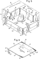
- eine perspektivische Schrägdraufsicht auf einen erfindungsgemäß ausgebildeten Eckbereich eines Akkumulators bei abgenommener Abdeckplatte,
- Fig. 1
- eine entsprechende perspektivische Ansicht der für die Ausführungsform nach Fig. 1 bestimmten Abdeckplatte,
- Fig. 3
- eine zu Fig. 1 analoge perspektivische Schrägdraufsicht einer weiteren Ausführungsform bei abgenommener Abdeckplatte,
- Fig. 4
- eine entsprechende perspektivische Schrägdraufsicht der Abdeckplatte für die Ausführungsform nach Fig.3,
- Fig. 5
- eine zu den Fig. 1 und 3 analoge perspektivische Schrägdraufsicht einer weiteren Ausführungsform bei abgenommener Abdeckplatte und
- Fig. 6
- eine perspektivische Schrägdraufsicht der Abdeckplatte für die Ausführungsform nach Fig. 5.
- Fig. 1
- 2 shows a perspective oblique top view of a corner region of an accumulator designed according to the invention with the cover plate removed,
- Fig. 1
- 3 shows a corresponding perspective view of the cover plate intended for the embodiment according to FIG. 1,
- Fig. 3
- 1 is a perspective oblique top view analogous to FIG. 1 of a further embodiment with the cover plate removed,
- Fig. 4
- a corresponding perspective oblique top view of the cover plate for the embodiment of Figure 3,
- Fig. 5
- an analog to FIGS. 1 and 3 perspective oblique plan view of a further embodiment with the cover plate and
- Fig. 6
- 5 shows a perspective oblique top view of the cover plate for the embodiment according to FIG. 5.
Nach Fig. 1 weist ein nur teilweise dargestelltes Akkumulatorgehäuse 24 einen Deckel 13 auf, der an seiner Unterseite mit einer rundumlaufenden und seitlich über das Gehäuse 24 vorspringenden Deckelschürze 33 versehen ist. Oberhalb der Deckelschürze 33 springt der Deckel 13 bei 38 wieder etwas zurück und bildet anschließend vertikale Seitenwände, von denen in Fig. 1 nur die bis zu Ecken 35, 39 verlaufenden Endteile 31, 32 dargestellt sind.According to FIG. 1, a
Im Bereich einer Ecke 19 der Deckelschürze 33 bzw. 40 des Gehäuses 24 weist der Deckel eine Vertiefung 12 von rechteckigem oder quadratischem Horizontalquerschnitt auf, deren Bodenfläche 14 mit der oberen Fläche 38 der Deckelschürze 33 bündig ist.In the region of a
Die Vertiefung 12 ist nach außen offen und nach innen durch rechtwinklig zueinander und vertikal angeordnete Seitenwände 16, 17 begrenzt sowie unten durch eine Bodenfläche 14 abgeschlossen.The
Von der Bodenfläche 14 erstreckt sich in deutlichem Abstand von den Seitenwänden 16, 17 und der Deckelschürze 33 ein vorzugsweise aus Blei bestehender Metallpol 11 senkrecht nach oben. In vertikaler Richtung ist seine Länge etwas geringer als die Höhe der Vertiefung 12.A
In der Deckeloberfläche 15 sind in gleichem Abstand hinter der Seitenwand 17 zwei voneinander beabstandete Löcher 21 vorgesehen, in welche an der Unterseite einer in Fig. 2 dargestellten Abdeckplatte 18 mitangespritzte, zu ihnen komplementäre Haltestifte 20 klemmend eingreifen können. Die Haltestifte 20 sind in einem gestrichelt angedeuteten Randstreifen 22 der Abdeckplatte 18 vorgesehen, welcher nach dem Aufsetzen der Abdeckplatte 18 auf den Deckel 13 nach Fig. 1 auf der Deckeloberfläche 15 zur Anlage kommt.Provided in the
Ein im rechten Winkel zu dem Randstreifen 22 vorgesehener Randstreifen 23 der Abdeckplatte 18 kommt beim Aufsetzen derselben auf den Deckel 13 auf einem schmalen Streifen der Deckeloberfläche 15 unmittelbar neben dem oberen Ende der Seitenwand 16 zur Auflage.An
Nahe dem von dem Randstreifen 22 abgewandten Rand 41 der Abdeckplatte 18 und unmittelbar neben dem anderen Randstreifen 23 erstreckt sich von der unteren Fläche der Abdeckplatte 18 ein als Federsteg ausgebildeter Vorsprung 34, der nach Art einer Blattfeder ausgebildet ist, deren Ebene parallel zur Ebene der Seitenwand 16 verläuft. Im unteren Bereich des Vorsprunges 34 ist ein sich zur Seitenwand 16 hin erstreckender Rastvorsprung 29 vorgesehen, der beim Aufsetzen der Abdeckplatte 18 auf den Deckel 13 nach Fig. 1 in eine in der Seitenwand 16 vorgesehene komplementäre Rastvertiefung 30 einschnappen kann.Near the
Parallel zum Randstreifen 22 bzw. zur Verbindungslinie der beiden Haltestifte 20 ist die Abdeckplatte 18 durch ein Scharnier 42 in zwei Teile 18', 18'' unterteilt, von denen einer 18' den Vorsprung 34 und der andere 18'' die Haltestifte 20 trägt. Die über den Ecken 19, 40 des Deckels bzw. Gehäuses liegende Ecke 18''' der Abdeckplatte 18 ist abgerundet.Parallel to the
Der Deckel 13 nach Fig. 1 ist aus durch eine horizontale Schweißebene 37 voneinander getrennten Deckelteilen 13', 13'' zusammengeschweißt.1 is welded together from
Die Montage der erfindungsgemäßen Abdeckplatte 18 geht wie folgt vor sich:
Nachdem die nicht dargestellten Kabelverbinder am Pol 11 angebracht sind, werden zunächst die Haltestifte 20 in die zugeordneten Löcher 21 eingesteckt, wobei der den Vorsprung 34 tragende Teil 18' der Abdeckplatte 18 um das Scharnier 42 etwas hochgeklappt sein kann. Sobald der Teil 18'' mit dem Randstreifen 22 vollständig auf der Deckeloberfläche 15 aufliegt, wird der den Vorsprung 34 tragende Teil 18' der Abdeckplatte 18 nach unten geklappt, wobei der Vorsprung 34 beim Entlanggleiten des Rastvorsprunges 29 an der Seitenwand 16 zunächst etwas von der Seitenwand 16 federnd weggebogen wird, bis schließlich der Rastvorsprung 29 in die Rastvertiefung 30 einschnappt, worauf die Abdeckplatte 18 endgültig festgelegt ist. Die kugelkuppenartige Ausbildung des Rastvorsprunges 29 und der Rastvertiefung 30 sorgen dafür, daß auch ein Ausrasten durch Hochheben der Abdeckplatte 18 möglich ist.The
After the cable connectors (not shown) are attached to the
Aufgrund der erfindungsgemäßen Ausbildung ist der gesamte Raum beidseits der Ecke 19 zwischen der Bodenfläche 14 und der aufgesetzten Abdeckplatte 18 frei für den Durchgang von Kabeln, die mit dem Pol 11 in Verbindung stehen.Due to the design according to the invention, the entire space on both sides of the
Die Verbindung zwischen dem Kabel und dem Pol 11 kann bei abgenommener Abdeckplatte 18 oder auch bei nur hochgeklapptem Teil 18' vorgenommen werden.The connection between the cable and the
Beim Ausführungsbeispiel nach den Fig. 3 und 4, in denen gleiche Teile mit gleichen Bezugszahlen wie in Fig. 1, 2 bezeichnet sind, ist der als Federsteg ausgebildete Vorsprung 34' in dem vom Randstreifen 22 abgewandten und dem Seitenwandendteil 31 zugewandten Eckbereich 18''' der Abdeckplatte 18 angeordnet. Der Vorsprung 34' ist wieder nach Art einer Blattfeder ausgebildet, wobei jedoch die Ebene des Vorsprunges 34' parallel zum Seitenwandendteil 31 bzw. senkrecht zur Seitenwand 16 verläuft, so daß der Rastvorsprung 25, der mit einer im Bereich der Ecke 35 vorgesehenen Rastvertiefung 26 zusammenarbeitet, von der Seitenwand 31 weg federnd verbiegbar ist.In the exemplary embodiment according to FIGS. 3 and 4, in which the same parts have the same reference numbers as in FIGS. 1, 2, the projection 34 'designed as a spring bar is in the corner region 18' 'facing away from the
Während beim Ausführungsbeispiel nach den Fig. 1 und 2 der Rastvorsprung 29 und der Vorsprung 34' vollständig im Bereich der Vertiefung 12 untergebracht sind, steht beim Ausführungsbeispiel nach den Fig. 3 und 4 der Vorsprung 34' um seine relativ geringe Dicke über die Seitenwand 31 vor. Die Dicke des Vorsprunges 34' ist jedoch so gering ausgebildet, daß ein seitliches Vorstehen über die Deckelschürze 33 vermieden ist. Andererseits können der Rastvorsprung 25 und die Rastvertiefung 26 problemlos so tief ausgebildet werden, daß eine sichere Rastverbindung geschaffen wird.1 and 2, the latching projection 29 and the projection 34 'are completely accommodated in the region of the
In dem Ausführungsbeispiel nach den Fig. 5 und 6, in denen wieder gleiche Bezugszahlen entsprechende Teile wie in den vorangehenden Figuren bezeichnen, ist gezeigt, daß die Rastvertiefung 28 auch dadurch verwirklicht werden kann, daß das Seitenwandteil 31 im oberen Bereich in die Vertiefung 12 hinein verlängert ist, wodurch ein Raststeg 36 vorliegt, unterhalb dessen die Rastvertiefung 28 ausgebildet ist. Unter den Raststeg 36 greift bei aufgesetzter Abdeckplatte 18 nach Fig. 6 ein Rastvorsprung 27, der an einem blattfederartig ausgebildeten Vorsprung 34' vorgesehen ist, welcher ähnlich wie in Fig. 4, also vom Seitenwandendteil 31 weg federnd ausgebildet ist. Grundsätzlich könnte der Raststeg 36 aber auch von einem Vorsprung untergriffen werden, der an einem Federsteg 34, wie er in Fig. 2 dargestellt ist, ausgebildet ist.5 and 6, in which again the same reference numerals designate corresponding parts as in the previous figures, it is shown that the locking recess 28 can also be realized in that the
Der Vorsprung 34' und der Rastvorsprung 27 sind nach Fig. 6 so schmal ausgebildet, daß eine Korrespondenz mit der Breite der Rastvertiefung 28 gegeben ist. Gegenüber dem auf der Deckeloberfläche 15 aufliegenden Randstreifen 23 sind der Vorsprung 34' und der Rastvorsprung 27 etwas zur Ecke 18''' hin versetzt. Auf diese Weise kann einerseits der Randstreifen 23 sicher auf der Deckeloberfläche 15 aufliegen und gleichzeitig der Federsteg 34' mit dem Rastvorsprung 27 einwandfrei mit der Rastvertiefung 28 zusammenarbeiten. Die durch die Versetzung des Vorsprunges 34' gegenüber dem Randstreifen 23 gebildete Stufe ist mit 43 bezeichnet.The projection 34 'and the locking projection 27 are so narrow in FIG. 6 that there is a correspondence with the width of the locking recess 28. In relation to the
Claims (20)
dadurch gekennzeichnet,
daß die Abdeckplatte (18) keine sich über die Außenkontur des Gehäuses (40) und/oder des Deckels (13) einschließlich einer etwaigen rundumlaufenden Deckelschürze (33) erstreckenden Teile aufweist und die Rastmittel (25, 26; 27, 28; 29, 30) im Bereich zwischen der Bodenfläche (14) und der Deckeloberfläche (15) vorgesehen sind.Accumulator with at least one metal pole (11) provided in a corner region of its cover (13), which has a preferably rectangular, in particular square, recess (12) that delimits inwards through walls (16, 17) that are perpendicular to the cover surface (15) and is open to the outside and from its preferably flat bottom surface (14) the metal pole (11) protrudes up to at most the lid surface (15), the depression (12) at the top by an edge strip (22, 23) merging into one another The cover surface (15) is covered with an essentially preferably rectangular or square cover plate (18), which has side holding means (20, 21) which fix it against movements parallel to the bottom surface (14), preferably by means of a pin (20) hole (21). -Connections between the lower surface of at least one of the edge strips (22, 23) and the cover (13) and preferably at least one downwardly extending projection g (34, 34 ') on the cover plate (18) comprising detent means (25, 26; 27, 28; 29, 30) is detachably held on the cover (13) and at least on one side of the corner (19) and in the area of the corner (19) between its lower surface and the bottom surface (14) there is a passage opening for a connection to the pole (11) leaves the cable to be connected,
characterized by
that the cover plate (18) does not extend over the outer contour of the housing (40) and / or the cover (13) including any circumferential cover apron (33) extending parts and the locking means (25, 26; 27, 28; 29, 30) are provided in the area between the bottom surface (14) and the cover surface (15).
dadurch gekennzeichnet,
daß die Rastmittel (25, 26; 27, 28; 29, 30) nur im Bereich der Seitenwände (16, 17) der Vertiefung (12) vorgesehen sind.Accumulator according to claim 1,
characterized by
that the locking means (25, 26; 27, 28; 29, 30) are provided only in the region of the side walls (16, 17) of the recess (12).
dadurch gekennzeichnet,
daß die Rastmittel (25, 26; 27, 28; 29, 30) oberhalb der Bodenfläche (14) zwischen dem sich von der Abdeckplatte (18) nach unten erstreckenden Vorsprung (34, 34') und den Seitenwänden (16, 17) der Vertiefung (12) vorgesehen sind.Accumulator according to claim 1 or 2,
characterized by
that the locking means (25, 26; 27, 28; 29, 30) above the bottom surface (14) between the projection (34, 34 ') extending downward from the cover plate (18) and the side walls (16, 17) of the Recess (12) are provided.
dadurch gekennzeichnet,
daß die Rastmittel eine Rastvertiefung (26, 28, 30) aufweisen, die oberhalb der Bodenfläche (14) in den Seitenwänden (16, 17) der Vertiefung (12) und/oder den in gleicher Höhe liegenden, diesen unmittelbar benachbarten Teilen (31, 32) der Seitenwände des Deckels (13) ausgebildet sind, und der Vorsprung (34, 34') der Abdeckplatte (18) einen mit der Rastvertiefung (26, 28, 30) zusammenarbeitenden Rastvorsprung (27, 29, 30) trägt und sich nach unten höchstens bis zur Bodenfläche 14 der Vertiefung (12) erstreckt.Accumulator according to one of the preceding claims,
characterized by
that the latching means have a latching recess (26, 28, 30) which above the bottom surface (14) in the side walls (16, 17) of the recess (12) and / or the parts (31, 32) of the side walls of the cover (13) are formed, and the projection (34, 34 ') of the cover plate (18) carries a locking projection (27, 29, 30) which cooperates with the locking recess (26, 28, 30) extends below at most to the bottom surface 14 of the depression (12).
dadurch gekennzeichnet,
daß sich die Rastvorsprünge (25, 27, 29) seitlich nicht über die Außenkontur des Deckels (13), insbesondere einer nach unten an ihm vorgesehenen Deckelschürze (33) und des Gehäuses (40) hinauserstrecken.Accumulator according to claim 4,
characterized by
that the locking projections (25, 27, 29) do not extend laterally beyond the outer contour of the cover (13), in particular a cover apron (33) and the housing (40) provided on it downwards.
dadurch gekennzeichnet,
daß die Abdeckplatte (18) an ihrem einen auf der Deckeloberfläche aufliegenden Randstreifen (22) wenigstens einen und vorzugsweise zwei sich nach unten in dazu komplementäre Bohrungen (21) des Deckels (25) erstreckende Haltestifte (20) trägt.Accumulator according to one of the preceding claims,
characterized by
that the cover plate (18) carries at its one edge strip resting on the cover surface (22) at least one and preferably two downward into complementary bores (21) of the cover (25) extending retaining pins (20).
dadurch gekennzeichnet,
daß der die Rastvorsprünge (25, 27, 29) tragende Vorsprung (34, 34') an oder nahe dem anderen Rand (23) angeordnet ist.Accumulator according to claim 6,
characterized by
that the locking projections (25, 27, 29) carrying projection (34, 34 ') is arranged on or near the other edge (23).
dadurch gekennzeichnet,
daß in einer (16) der Seitenwände (16, 17) der Vertiefung (12) eine Rastvertiefung (30) vorgesehen ist, in die ein an dem sich von einem randnahen Bereich der Abdeckplatte (18) nach unten erstreckenden, als senkrecht von der Seitenwand (16) federnd wegbiegbarer Federsteg ausgebildeten Vorsprung (34) vorgesehener Rastvorsprung (29) lösbar eingreift.Accumulator according to one of the preceding claims,
characterized by
that in one (16) of the side walls (16, 17) of the recess (12) there is provided a latching recess (30) into which one extends downwards from the region of the cover plate (18) near the edge, as perpendicular to the side wall (16) spring-bendable spring bar formed projection (34) detent projection (29) releasably engages.
dadurch gekennzeichnet,
daß die Rastvertiefung (30) nahe der Ecke (35) angeordnet ist, wo die Seitenwand (16) der Vertiefung (12) in die Seitenwand (31) des Deckels (15) übergeht.Accumulator according to claim 8,
characterized by
that the locking recess (30) is arranged near the corner (35) where the side wall (16) of the recess (12) merges into the side wall (31) of the cover (15).
dadurch gekennzeichnet,
daß im Bereich der Ecke (35) zwischen einer der Seitenwände (16) der Vertiefung (12) und der angrenzenden Seitenwand (31) des Deckels (15) eine Rastvertiefung (26) vorgesehen ist, in die ein an dem sich von der Abdeckplatte (18) nach unten erstreckenden, als Federsteg ausgebildeten Vorsprung (34') vorgesehener Rastvorsprung (25) eingreift.Accumulator according to one of claims 1 to 7,
characterized by
that in the area of the corner (35) between one of the side walls (16) of the recess (12) and the adjoining side wall (31) of the cover (15) there is a latching recess (26) into which a cover plate ( 18) engages downward, provided as a spring bar projection (34 ') provided locking projection (25).
dadurch gekennzeichnet,
daß der Vorsprung (34') in Richtung von einer der Seitenwände (16, 31) oder der Ecke (35) weg federnd biegbar ist, um den Rastvorsprung (25) und die Rastvertiefung (26) außer Eingriff bringen zu können.Accumulator according to claim 10,
characterized by
that the projection (34 ') in the direction of one of the side walls (16, 31) or the corner (35) is resiliently bendable in order to be able to disengage the latching projection (25) and the latching recess (26).
dadurch gekennzeichnet,
daß zur Bildung einer Rastvertiefung (28) von einer der Seitenwände (16, 17) der Vertiefung (12) ein Raststeg (36) in solchem Abstand von der Bodenfläche (14) der Vertiefung (12) vorspringt, daß darunter die Rastvertiefung (28) ausgebildet ist.Accumulator according to one of claims 1 to 7,
characterized by
that to form a locking recess (28) from one of the side walls (16, 17) of the recess (12), a locking web (36) projects from the bottom surface (14) of the recess (12) to such an extent that the locking recess (28) is trained.
dadurch gekennzeichnet,
daß der Raststeg (36) sich im oberen Bereich der zugeordneten Seitenwand (16, 17) befindet.Accumulator according to claim 12,
characterized by
that the locking web (36) is in the upper region of the associated side wall (16, 17).
dadurch gekennzeichnet,
daß der Raststeg (36) an der Ecke (35) zum benachbarten Teil (31) der Seitenwand des Deckels (13) vorgesehen ist.Accumulator according to claim 12 or 13,
characterized by
that the locking web (36) is provided at the corner (35) to the adjacent part (31) of the side wall of the cover (13).
dadurch gekennzeichnet,
daß der Raststeg (36) als Verlängerung des oberen Teils der benachbarten Seitenwand (31) des Deckels (15) ausgebildet ist.Accumulator according to claim 14,
characterized by
that the locking web (36) is designed as an extension of the upper part of the adjacent side wall (31) of the cover (15).
dadurch gekennzeichnet,
daß der Deckel (13) aus zwei durch eine horizontale Schweißebene (37) voneinander getrennten Deckelteilen (13', 13'') besteht.Accumulator according to one of the preceding claims,
characterized by
that the cover (13) consists of two cover parts (13 ', 13'') separated from one another by a horizontal welding plane (37).
dadurch gekennzeichnet,
daß parallel zu dem durch die Seitenhaltemittel (21, 22), insbesondere die Haltestifte (20) und Bohrungen (21) am Deckel (13) gehaltenen Randstreifen (22) die Abdeckplatte (18) ein Scharnier (42) aufweist, um das der den Rastvorsprung (25, 27, 29) tragende Teil (18') der Abdeckplatte (18) nach oben bzw. unten klappbar ist, wobei die Rastmittel (25, 26; 27, 28; 29, 30) so ausgebildet sind, daß sie durch Herumklappen des sie tragenden Teils (18') um das Scharnier (42) in und außer Eingriff miteinander bringbar sind.Accumulator according to one of the preceding claims,
characterized by
that parallel to the edge strip (22) held by the side holding means (21, 22), in particular the holding pins (20) and bores (21) on the cover (13), the cover plate (18) has a hinge (42) around which the Locking projection (25, 27, 29) supporting part (18 ') of the cover plate (18) can be folded up or down, the locking means (25, 26; 27, 28; 29, 30) being designed such that they are by Folding the part (18 ') carrying it around the hinge (42) can be brought into and out of engagement with one another.
dadurch gekennzeichnet,
daß das Scharnier (42) sich im Bereich des oberen Randes der zugeordneten Seitenwand (17) befindet.Accumulator according to claim 17,
characterized by
that the hinge (42) is located in the area of the upper edge of the associated side wall (17).
dadurch gekennzeichnet,
daß das Scharnier (42) durch eine vorzugsweise in der unteren Fläche der Abdeckplatte (18) vorgesehene Rille realisiert ist.Accumulator according to claim 17 or 18,
characterized by
that the hinge (42) through a groove provided preferably in the lower surface of the cover plate (18) is realized.
dadurch gekennzeichnet,
daß die Ränder der Abdeckplatte (18) mit den oberen Rändern der Seitenwände (31, 32) des Deckels (15) fluchten und/oder ihre mit der Ecke (19, 40) des Deckels (13) bzw. des Gehäuses (24) fluchtende Ecke (18''') abgerundet ist.Accumulator according to one of the preceding claims,
characterized by
that the edges of the cover plate (18) are flush with the upper edges of the side walls (31, 32) of the cover (15) and / or are flush with the corner (19, 40) of the cover (13) or the housing (24) Corner (18 ''') is rounded.
Applications Claiming Priority (2)
| Application Number | Priority Date | Filing Date | Title |
|---|---|---|---|
| DE4300567 | 1993-01-12 | ||
| DE4300567A DE4300567A1 (en) | 1993-01-12 | 1993-01-12 | Accumulator with removable cover plate covering the poles |
Publications (3)
| Publication Number | Publication Date |
|---|---|
| EP0606850A2 true EP0606850A2 (en) | 1994-07-20 |
| EP0606850A3 EP0606850A3 (en) | 1997-01-29 |
| EP0606850B1 EP0606850B1 (en) | 2000-09-20 |
Family
ID=6478018
Family Applications (1)
| Application Number | Title | Priority Date | Filing Date |
|---|---|---|---|
| EP94100126A Expired - Lifetime EP0606850B1 (en) | 1993-01-12 | 1994-01-05 | Battery with detachable cover plate covering the terminals |
Country Status (4)
| Country | Link |
|---|---|
| EP (1) | EP0606850B1 (en) |
| AT (1) | ATE196563T1 (en) |
| DE (2) | DE4300567A1 (en) |
| ES (1) | ES2149826T3 (en) |
Cited By (3)
| Publication number | Priority date | Publication date | Assignee | Title |
|---|---|---|---|---|
| CN105934839A (en) * | 2014-01-21 | 2016-09-07 | 株式会社Lg化学 | Battery pack |
| CN107615517A (en) * | 2015-12-23 | 2018-01-19 | 株式会社Lg化学 | Secondary battery |
| US20180175342A1 (en) * | 2015-12-18 | 2018-06-21 | Lg Chem, Ltd. | Secondary battery pack |
Families Citing this family (1)
| Publication number | Priority date | Publication date | Assignee | Title |
|---|---|---|---|---|
| WO2020163712A1 (en) * | 2019-02-08 | 2020-08-13 | Cps Technology Holdings Llc | Terminal cover |
Citations (3)
| Publication number | Priority date | Publication date | Assignee | Title |
|---|---|---|---|---|
| GB1548129A (en) * | 1978-02-17 | 1979-07-04 | Chloride Group Ltd | Electric storage battery lids |
| DE3333308A1 (en) * | 1983-09-15 | 1985-03-28 | Ford-Werke AG, 5000 Köln | LADDER CONNECTION FOR STARTER BATTERIES, IN PARTICULAR OF MOTOR VEHICLES |
| EP0306746A1 (en) * | 1987-09-03 | 1989-03-15 | VARTA Batterie Aktiengesellschaft | Storage battery |
Family Cites Families (2)
| Publication number | Priority date | Publication date | Assignee | Title |
|---|---|---|---|---|
| US3937636A (en) * | 1975-06-12 | 1976-02-10 | Eltra Corporation | Battery with recessed terminals and fuse |
| DE7826754U1 (en) * | 1978-09-08 | 1980-05-08 | Accumulatorenfabrik Sonnenschein Gmbh, 6470 Buedingen | DEVICE FOR COVERING THE CONNECTING POLES PROJECTING UP FROM THE LID OF A ACCUMULATOR |
-
1993
- 1993-01-12 DE DE4300567A patent/DE4300567A1/en not_active Withdrawn
-
1994
- 1994-01-05 EP EP94100126A patent/EP0606850B1/en not_active Expired - Lifetime
- 1994-01-05 AT AT94100126T patent/ATE196563T1/en not_active IP Right Cessation
- 1994-01-05 ES ES94100126T patent/ES2149826T3/en not_active Expired - Lifetime
- 1994-01-05 DE DE59409524T patent/DE59409524D1/en not_active Expired - Fee Related
Patent Citations (3)
| Publication number | Priority date | Publication date | Assignee | Title |
|---|---|---|---|---|
| GB1548129A (en) * | 1978-02-17 | 1979-07-04 | Chloride Group Ltd | Electric storage battery lids |
| DE3333308A1 (en) * | 1983-09-15 | 1985-03-28 | Ford-Werke AG, 5000 Köln | LADDER CONNECTION FOR STARTER BATTERIES, IN PARTICULAR OF MOTOR VEHICLES |
| EP0306746A1 (en) * | 1987-09-03 | 1989-03-15 | VARTA Batterie Aktiengesellschaft | Storage battery |
Cited By (9)
| Publication number | Priority date | Publication date | Assignee | Title |
|---|---|---|---|---|
| CN105934839A (en) * | 2014-01-21 | 2016-09-07 | 株式会社Lg化学 | Battery pack |
| EP3093908A4 (en) * | 2014-01-21 | 2017-07-12 | LG Chem, Ltd. | Battery pack |
| US10020486B2 (en) | 2014-01-21 | 2018-07-10 | Lg Chem, Ltd. | Battery pack |
| CN105934839B (en) * | 2014-01-21 | 2018-09-18 | 株式会社Lg 化学 | Battery pack |
| US20180175342A1 (en) * | 2015-12-18 | 2018-06-21 | Lg Chem, Ltd. | Secondary battery pack |
| US11374277B2 (en) * | 2015-12-18 | 2022-06-28 | Lg Energy Solution, Ltd. | Secondary battery pack |
| CN107615517A (en) * | 2015-12-23 | 2018-01-19 | 株式会社Lg化学 | Secondary battery |
| US20180145289A1 (en) * | 2015-12-23 | 2018-05-24 | Lg Chem, Ltd. | Secondary battery pack |
| US10581035B2 (en) * | 2015-12-23 | 2020-03-03 | Lg Chem, Ltd. | Secondary battery pack |
Also Published As
| Publication number | Publication date |
|---|---|
| EP0606850B1 (en) | 2000-09-20 |
| ATE196563T1 (en) | 2000-10-15 |
| DE4300567A1 (en) | 1994-07-14 |
| EP0606850A3 (en) | 1997-01-29 |
| DE59409524D1 (en) | 2000-10-26 |
| ES2149826T3 (en) | 2000-11-16 |
Similar Documents
| Publication | Publication Date | Title |
|---|---|---|
| DE69923051T2 (en) | Lockable electrical connector | |
| DE2656178C2 (en) | Device for connecting pontoons | |
| DE3042116A1 (en) | PORTABLE DISPLAY SYSTEM | |
| DE2054201B2 (en) | Electrical contact element intended for use in an electrical connector | |
| DE2205011B2 (en) | Covering device for the front surface of an electrical socket | |
| DE3309665A1 (en) | CABLE GLANDS | |
| DE60110954T2 (en) | Cassettes and drawer for drawer cabinets | |
| EP3865716B1 (en) | Clamp for a detachable connection of construction elements | |
| DE3303764A1 (en) | ELECTRICAL INSTALLATION DEVICE | |
| EP0606850B1 (en) | Battery with detachable cover plate covering the terminals | |
| DE3035669A1 (en) | Retaining mechanism with hooked arms on front plate - has arms snapping into holes in box and disengaged from holes by sliding laterally along ramps | |
| DE19540112B4 (en) | Housings for the installation, insulation and encapsulation of electrical, electronic and pneumatic devices and devices | |
| WO1994022183A1 (en) | Plug connector with cable passage | |
| DE2557697C3 (en) | Covering device with a pivotable cover for the housing of a device | |
| DE7833886U1 (en) | Installation housing made of plastic | |
| DE8521953U1 (en) | Electrical plug | |
| DE2846155C2 (en) | switch cabinet | |
| DE69821614T2 (en) | SAFETY DEVICE FOR ELECTRICAL CONNECTORS WITH POWER RAILS, INSTALLATION CHANNELS AND SIMILAR. | |
| DE3842205C2 (en) | Housing for the connection of communication systems | |
| DE2719841B2 (en) | Multipole connector for low-voltage systems, in particular telephone systems | |
| DE2928118C2 (en) | Control panel element, in particular automatic circuit breaker or disconnector, designed for side-by-side fastening on a mounting rail | |
| DE3145203A1 (en) | Cassette for receiving elongate articles | |
| DE2714885C3 (en) | Wiring duct | |
| EP0378065A2 (en) | Part of a case with a plug mounted thereon | |
| DE3604548A1 (en) | Mating and un mating camming system for PCB connector assembly |
Legal Events
| Date | Code | Title | Description |
|---|---|---|---|
| PUAI | Public reference made under article 153(3) epc to a published international application that has entered the european phase |
Free format text: ORIGINAL CODE: 0009012 |
|
| AK | Designated contracting states |
Kind code of ref document: A2 Designated state(s): AT CH DE DK ES FR GB IT LI LU PT SE |
|
| PUAL | Search report despatched |
Free format text: ORIGINAL CODE: 0009013 |
|
| AK | Designated contracting states |
Kind code of ref document: A3 Designated state(s): AT CH DE DK ES FR GB IT LI LU PT SE |
|
| 17P | Request for examination filed |
Effective date: 19970716 |
|
| 17Q | First examination report despatched |
Effective date: 19980218 |
|
| GRAG | Despatch of communication of intention to grant |
Free format text: ORIGINAL CODE: EPIDOS AGRA |
|
| 17Q | First examination report despatched |
Effective date: 19980218 |
|
| GRAG | Despatch of communication of intention to grant |
Free format text: ORIGINAL CODE: EPIDOS AGRA |
|
| GRAH | Despatch of communication of intention to grant a patent |
Free format text: ORIGINAL CODE: EPIDOS IGRA |
|
| GRAH | Despatch of communication of intention to grant a patent |
Free format text: ORIGINAL CODE: EPIDOS IGRA |
|
| GRAA | (expected) grant |
Free format text: ORIGINAL CODE: 0009210 |
|
| ITF | It: translation for a ep patent filed |
Owner name: BARZANO' E ZANARDO MILANO S.P.A. |
|
| AK | Designated contracting states |
Kind code of ref document: B1 Designated state(s): AT CH DE DK ES FR GB IT LI LU PT SE |
|
| REF | Corresponds to: |
Ref document number: 196563 Country of ref document: AT Date of ref document: 20001015 Kind code of ref document: T |
|
| REG | Reference to a national code |
Ref country code: CH Ref legal event code: EP |
|
| GBT | Gb: translation of ep patent filed (gb section 77(6)(a)/1977) |
Effective date: 20000920 |
|
| REF | Corresponds to: |
Ref document number: 59409524 Country of ref document: DE Date of ref document: 20001026 |
|
| ET | Fr: translation filed | ||
| REG | Reference to a national code |
Ref country code: ES Ref legal event code: FG2A Ref document number: 2149826 Country of ref document: ES Kind code of ref document: T3 |
|
| PGFP | Annual fee paid to national office [announced via postgrant information from national office to epo] |
Ref country code: FR Payment date: 20001120 Year of fee payment: 8 |
|
| PGFP | Annual fee paid to national office [announced via postgrant information from national office to epo] |
Ref country code: GB Payment date: 20001127 Year of fee payment: 8 |
|
| PG25 | Lapsed in a contracting state [announced via postgrant information from national office to epo] |
Ref country code: PT Free format text: LAPSE BECAUSE OF FAILURE TO SUBMIT A TRANSLATION OF THE DESCRIPTION OR TO PAY THE FEE WITHIN THE PRESCRIBED TIME-LIMIT Effective date: 20001220 Ref country code: DK Free format text: LAPSE BECAUSE OF FAILURE TO SUBMIT A TRANSLATION OF THE DESCRIPTION OR TO PAY THE FEE WITHIN THE PRESCRIBED TIME-LIMIT Effective date: 20001220 |
|
| PG25 | Lapsed in a contracting state [announced via postgrant information from national office to epo] |
Ref country code: LU Free format text: LAPSE BECAUSE OF NON-PAYMENT OF DUE FEES Effective date: 20010105 Ref country code: AT Free format text: LAPSE BECAUSE OF NON-PAYMENT OF DUE FEES Effective date: 20010105 |
|
| PGFP | Annual fee paid to national office [announced via postgrant information from national office to epo] |
Ref country code: ES Payment date: 20010123 Year of fee payment: 8 |
|
| PGFP | Annual fee paid to national office [announced via postgrant information from national office to epo] |
Ref country code: SE Payment date: 20010130 Year of fee payment: 8 |
|
| PG25 | Lapsed in a contracting state [announced via postgrant information from national office to epo] |
Ref country code: LI Free format text: LAPSE BECAUSE OF NON-PAYMENT OF DUE FEES Effective date: 20010131 Ref country code: CH Free format text: LAPSE BECAUSE OF NON-PAYMENT OF DUE FEES Effective date: 20010131 |
|
| PGFP | Annual fee paid to national office [announced via postgrant information from national office to epo] |
Ref country code: DE Payment date: 20010228 Year of fee payment: 8 |
|
| PLBE | No opposition filed within time limit |
Free format text: ORIGINAL CODE: 0009261 |
|
| STAA | Information on the status of an ep patent application or granted ep patent |
Free format text: STATUS: NO OPPOSITION FILED WITHIN TIME LIMIT |
|
| 26N | No opposition filed | ||
| REG | Reference to a national code |
Ref country code: CH Ref legal event code: PL |
|
| REG | Reference to a national code |
Ref country code: GB Ref legal event code: IF02 |
|
| PG25 | Lapsed in a contracting state [announced via postgrant information from national office to epo] |
Ref country code: GB Free format text: LAPSE BECAUSE OF NON-PAYMENT OF DUE FEES Effective date: 20020105 |
|
| PG25 | Lapsed in a contracting state [announced via postgrant information from national office to epo] |
Ref country code: SE Free format text: LAPSE BECAUSE OF NON-PAYMENT OF DUE FEES Effective date: 20020106 |
|
| PG25 | Lapsed in a contracting state [announced via postgrant information from national office to epo] |
Ref country code: ES Free format text: LAPSE BECAUSE OF NON-PAYMENT OF DUE FEES Effective date: 20020108 |
|
| PG25 | Lapsed in a contracting state [announced via postgrant information from national office to epo] |
Ref country code: DE Free format text: LAPSE BECAUSE OF NON-PAYMENT OF DUE FEES Effective date: 20020801 |
|
| EUG | Se: european patent has lapsed |
Ref document number: 94100126.5 |
|
| GBPC | Gb: european patent ceased through non-payment of renewal fee |
Effective date: 20020105 |
|
| PG25 | Lapsed in a contracting state [announced via postgrant information from national office to epo] |
Ref country code: FR Free format text: LAPSE BECAUSE OF NON-PAYMENT OF DUE FEES Effective date: 20020930 |
|
| REG | Reference to a national code |
Ref country code: FR Ref legal event code: ST |
|
| REG | Reference to a national code |
Ref country code: ES Ref legal event code: FD2A Effective date: 20030922 |
|
| PG25 | Lapsed in a contracting state [announced via postgrant information from national office to epo] |
Ref country code: IT Free format text: LAPSE BECAUSE OF NON-PAYMENT OF DUE FEES;WARNING: LAPSES OF ITALIAN PATENTS WITH EFFECTIVE DATE BEFORE 2007 MAY HAVE OCCURRED AT ANY TIME BEFORE 2007. THE CORRECT EFFECTIVE DATE MAY BE DIFFERENT FROM THE ONE RECORDED. Effective date: 20050105 |