EP3865716B1 - Clamp for a detachable connection of construction elements - Google Patents
Clamp for a detachable connection of construction elements Download PDFInfo
- Publication number
- EP3865716B1 EP3865716B1 EP21155221.1A EP21155221A EP3865716B1 EP 3865716 B1 EP3865716 B1 EP 3865716B1 EP 21155221 A EP21155221 A EP 21155221A EP 3865716 B1 EP3865716 B1 EP 3865716B1
- Authority
- EP
- European Patent Office
- Prior art keywords
- closure element
- longitudinal
- component
- height
- longitudinal elements
- Prior art date
- Legal status (The legal status is an assumption and is not a legal conclusion. Google has not performed a legal analysis and makes no representation as to the accuracy of the status listed.)
- Active
Links
- 238000010276 construction Methods 0.000 title description 5
- 238000000034 method Methods 0.000 claims description 5
- 238000004806 packaging method and process Methods 0.000 claims description 4
- 230000008520 organization Effects 0.000 claims description 3
- 230000000149 penetrating effect Effects 0.000 claims description 3
- 238000007373 indentation Methods 0.000 description 36
- 238000004519 manufacturing process Methods 0.000 description 7
- 230000004308 accommodation Effects 0.000 description 2
- 230000009471 action Effects 0.000 description 2
- 230000007423 decrease Effects 0.000 description 2
- 230000000694 effects Effects 0.000 description 2
- 239000000463 material Substances 0.000 description 2
- 238000012986 modification Methods 0.000 description 2
- 230000004048 modification Effects 0.000 description 2
- 238000006748 scratching Methods 0.000 description 2
- 230000002393 scratching effect Effects 0.000 description 2
- 241000826860 Trapezium Species 0.000 description 1
- 230000008901 benefit Effects 0.000 description 1
- 239000003086 colorant Substances 0.000 description 1
- 230000001419 dependent effect Effects 0.000 description 1
- 238000005516 engineering process Methods 0.000 description 1
- 210000004905 finger nail Anatomy 0.000 description 1
- 238000001746 injection moulding Methods 0.000 description 1
- 239000004033 plastic Substances 0.000 description 1
- 229920003023 plastic Polymers 0.000 description 1
- 230000009467 reduction Effects 0.000 description 1
- 230000000717 retained effect Effects 0.000 description 1
- 230000035939 shock Effects 0.000 description 1
Images


Classifications
-
- F—MECHANICAL ENGINEERING; LIGHTING; HEATING; WEAPONS; BLASTING
- F16—ENGINEERING ELEMENTS AND UNITS; GENERAL MEASURES FOR PRODUCING AND MAINTAINING EFFECTIVE FUNCTIONING OF MACHINES OR INSTALLATIONS; THERMAL INSULATION IN GENERAL
- F16B—DEVICES FOR FASTENING OR SECURING CONSTRUCTIONAL ELEMENTS OR MACHINE PARTS TOGETHER, e.g. NAILS, BOLTS, CIRCLIPS, CLAMPS, CLIPS OR WEDGES; JOINTS OR JOINTING
- F16B45/00—Hooks; Eyes
- F16B45/06—Hooks with two symmetrically-pivoting hook parts within the same locking cavity
-
- F—MECHANICAL ENGINEERING; LIGHTING; HEATING; WEAPONS; BLASTING
- F16—ENGINEERING ELEMENTS AND UNITS; GENERAL MEASURES FOR PRODUCING AND MAINTAINING EFFECTIVE FUNCTIONING OF MACHINES OR INSTALLATIONS; THERMAL INSULATION IN GENERAL
- F16B—DEVICES FOR FASTENING OR SECURING CONSTRUCTIONAL ELEMENTS OR MACHINE PARTS TOGETHER, e.g. NAILS, BOLTS, CIRCLIPS, CLAMPS, CLIPS OR WEDGES; JOINTS OR JOINTING
- F16B2/00—Friction-grip releasable fastenings
- F16B2/02—Clamps, i.e. with gripping action effected by positive means other than the inherent resistance to deformation of the material of the fastening
- F16B2/06—Clamps, i.e. with gripping action effected by positive means other than the inherent resistance to deformation of the material of the fastening external, i.e. with contracting action
- F16B2/10—Clamps, i.e. with gripping action effected by positive means other than the inherent resistance to deformation of the material of the fastening external, i.e. with contracting action using pivoting jaws
-
- A—HUMAN NECESSITIES
- A47—FURNITURE; DOMESTIC ARTICLES OR APPLIANCES; COFFEE MILLS; SPICE MILLS; SUCTION CLEANERS IN GENERAL
- A47B—TABLES; DESKS; OFFICE FURNITURE; CABINETS; DRAWERS; GENERAL DETAILS OF FURNITURE
- A47B47/00—Cabinets, racks or shelf units, characterised by features related to dismountability or building-up from elements
- A47B47/0075—Flat or flat-like panels connected without frames
-
- F—MECHANICAL ENGINEERING; LIGHTING; HEATING; WEAPONS; BLASTING
- F16—ENGINEERING ELEMENTS AND UNITS; GENERAL MEASURES FOR PRODUCING AND MAINTAINING EFFECTIVE FUNCTIONING OF MACHINES OR INSTALLATIONS; THERMAL INSULATION IN GENERAL
- F16B—DEVICES FOR FASTENING OR SECURING CONSTRUCTIONAL ELEMENTS OR MACHINE PARTS TOGETHER, e.g. NAILS, BOLTS, CIRCLIPS, CLAMPS, CLIPS OR WEDGES; JOINTS OR JOINTING
- F16B12/00—Jointing of furniture or the like, e.g. hidden from exterior
- F16B12/10—Jointing of furniture or the like, e.g. hidden from exterior using pegs, bolts, tenons, clamps, clips, or the like
- F16B12/12—Jointing of furniture or the like, e.g. hidden from exterior using pegs, bolts, tenons, clamps, clips, or the like for non-metal furniture parts, e.g. made of wood, of plastics
- F16B12/20—Jointing of furniture or the like, e.g. hidden from exterior using pegs, bolts, tenons, clamps, clips, or the like for non-metal furniture parts, e.g. made of wood, of plastics using clamps, clips, wedges, sliding bolts, or the like
-
- F—MECHANICAL ENGINEERING; LIGHTING; HEATING; WEAPONS; BLASTING
- F16—ENGINEERING ELEMENTS AND UNITS; GENERAL MEASURES FOR PRODUCING AND MAINTAINING EFFECTIVE FUNCTIONING OF MACHINES OR INSTALLATIONS; THERMAL INSULATION IN GENERAL
- F16B—DEVICES FOR FASTENING OR SECURING CONSTRUCTIONAL ELEMENTS OR MACHINE PARTS TOGETHER, e.g. NAILS, BOLTS, CIRCLIPS, CLAMPS, CLIPS OR WEDGES; JOINTS OR JOINTING
- F16B12/00—Jointing of furniture or the like, e.g. hidden from exterior
- F16B12/10—Jointing of furniture or the like, e.g. hidden from exterior using pegs, bolts, tenons, clamps, clips, or the like
- F16B12/12—Jointing of furniture or the like, e.g. hidden from exterior using pegs, bolts, tenons, clamps, clips, or the like for non-metal furniture parts, e.g. made of wood, of plastics
- F16B12/26—Jointing of furniture or the like, e.g. hidden from exterior using pegs, bolts, tenons, clamps, clips, or the like for non-metal furniture parts, e.g. made of wood, of plastics using snap-action elements
-
- F—MECHANICAL ENGINEERING; LIGHTING; HEATING; WEAPONS; BLASTING
- F16—ENGINEERING ELEMENTS AND UNITS; GENERAL MEASURES FOR PRODUCING AND MAINTAINING EFFECTIVE FUNCTIONING OF MACHINES OR INSTALLATIONS; THERMAL INSULATION IN GENERAL
- F16B—DEVICES FOR FASTENING OR SECURING CONSTRUCTIONAL ELEMENTS OR MACHINE PARTS TOGETHER, e.g. NAILS, BOLTS, CIRCLIPS, CLAMPS, CLIPS OR WEDGES; JOINTS OR JOINTING
- F16B17/00—Connecting constructional elements or machine parts by a part of or on one member entering a hole in the other and involving plastic deformation
- F16B17/008—Connecting constructional elements or machine parts by a part of or on one member entering a hole in the other and involving plastic deformation of sheets or plates mutually
-
- F—MECHANICAL ENGINEERING; LIGHTING; HEATING; WEAPONS; BLASTING
- F16—ENGINEERING ELEMENTS AND UNITS; GENERAL MEASURES FOR PRODUCING AND MAINTAINING EFFECTIVE FUNCTIONING OF MACHINES OR INSTALLATIONS; THERMAL INSULATION IN GENERAL
- F16B—DEVICES FOR FASTENING OR SECURING CONSTRUCTIONAL ELEMENTS OR MACHINE PARTS TOGETHER, e.g. NAILS, BOLTS, CIRCLIPS, CLAMPS, CLIPS OR WEDGES; JOINTS OR JOINTING
- F16B5/00—Joining sheets or plates, e.g. panels, to one another or to strips or bars parallel to them
- F16B5/0004—Joining sheets, plates or panels in abutting relationship
- F16B5/0008—Joining sheets, plates or panels in abutting relationship by moving the sheets, plates or panels substantially in their own plane, perpendicular to the abutting edge
- F16B5/0012—Joining sheets, plates or panels in abutting relationship by moving the sheets, plates or panels substantially in their own plane, perpendicular to the abutting edge a tongue on the edge of one sheet, plate or panel co-operating with a groove in the edge of another sheet, plate or panel
-
- F—MECHANICAL ENGINEERING; LIGHTING; HEATING; WEAPONS; BLASTING
- F16—ENGINEERING ELEMENTS AND UNITS; GENERAL MEASURES FOR PRODUCING AND MAINTAINING EFFECTIVE FUNCTIONING OF MACHINES OR INSTALLATIONS; THERMAL INSULATION IN GENERAL
- F16B—DEVICES FOR FASTENING OR SECURING CONSTRUCTIONAL ELEMENTS OR MACHINE PARTS TOGETHER, e.g. NAILS, BOLTS, CIRCLIPS, CLAMPS, CLIPS OR WEDGES; JOINTS OR JOINTING
- F16B5/00—Joining sheets or plates, e.g. panels, to one another or to strips or bars parallel to them
- F16B5/06—Joining sheets or plates, e.g. panels, to one another or to strips or bars parallel to them by means of clamps or clips
- F16B5/0607—Joining sheets or plates, e.g. panels, to one another or to strips or bars parallel to them by means of clamps or clips joining sheets or plates to each other
- F16B5/0614—Joining sheets or plates, e.g. panels, to one another or to strips or bars parallel to them by means of clamps or clips joining sheets or plates to each other in angled relationship
-
- F—MECHANICAL ENGINEERING; LIGHTING; HEATING; WEAPONS; BLASTING
- F16—ENGINEERING ELEMENTS AND UNITS; GENERAL MEASURES FOR PRODUCING AND MAINTAINING EFFECTIVE FUNCTIONING OF MACHINES OR INSTALLATIONS; THERMAL INSULATION IN GENERAL
- F16B—DEVICES FOR FASTENING OR SECURING CONSTRUCTIONAL ELEMENTS OR MACHINE PARTS TOGETHER, e.g. NAILS, BOLTS, CIRCLIPS, CLAMPS, CLIPS OR WEDGES; JOINTS OR JOINTING
- F16B5/00—Joining sheets or plates, e.g. panels, to one another or to strips or bars parallel to them
- F16B5/06—Joining sheets or plates, e.g. panels, to one another or to strips or bars parallel to them by means of clamps or clips
- F16B5/0607—Joining sheets or plates, e.g. panels, to one another or to strips or bars parallel to them by means of clamps or clips joining sheets or plates to each other
- F16B2005/0678—Joining sheets or plates, e.g. panels, to one another or to strips or bars parallel to them by means of clamps or clips joining sheets or plates to each other in abutting relationship
-
- F—MECHANICAL ENGINEERING; LIGHTING; HEATING; WEAPONS; BLASTING
- F16—ENGINEERING ELEMENTS AND UNITS; GENERAL MEASURES FOR PRODUCING AND MAINTAINING EFFECTIVE FUNCTIONING OF MACHINES OR INSTALLATIONS; THERMAL INSULATION IN GENERAL
- F16B—DEVICES FOR FASTENING OR SECURING CONSTRUCTIONAL ELEMENTS OR MACHINE PARTS TOGETHER, e.g. NAILS, BOLTS, CIRCLIPS, CLAMPS, CLIPS OR WEDGES; JOINTS OR JOINTING
- F16B21/00—Means for preventing relative axial movement of a pin, spigot, shaft or the like and a member surrounding it; Stud-and-socket releasable fastenings
- F16B21/10—Means for preventing relative axial movement of a pin, spigot, shaft or the like and a member surrounding it; Stud-and-socket releasable fastenings by separate parts
- F16B21/16—Means for preventing relative axial movement of a pin, spigot, shaft or the like and a member surrounding it; Stud-and-socket releasable fastenings by separate parts with grooves or notches in the pin or shaft
-
- F—MECHANICAL ENGINEERING; LIGHTING; HEATING; WEAPONS; BLASTING
- F16—ENGINEERING ELEMENTS AND UNITS; GENERAL MEASURES FOR PRODUCING AND MAINTAINING EFFECTIVE FUNCTIONING OF MACHINES OR INSTALLATIONS; THERMAL INSULATION IN GENERAL
- F16B—DEVICES FOR FASTENING OR SECURING CONSTRUCTIONAL ELEMENTS OR MACHINE PARTS TOGETHER, e.g. NAILS, BOLTS, CIRCLIPS, CLAMPS, CLIPS OR WEDGES; JOINTS OR JOINTING
- F16B2200/00—Constructional details of connections not covered for in other groups of this subclass
- F16B2200/40—Clamping arrangements where clamping parts are received in recesses of elements to be connected
Definitions
- the present invention relates to a system for the detachable connection of components, in particular for the detachable connection of components, e.g transport packaging.
- Kits e.g. for furniture systems, are known from the prior art, which use elastic rubber bands or rubber rings to detachably connect the various elements.
- the DE 20 2014 103 445 U1 to a stacking shelf member and a cover panel member intended for use in a modular stacking shelf comprising at least one such stacking shelf member.
- the various plate elements are connected to one another using O-rings (rubber rings).
- the plate elements have projecting edge portions with an indentation at opposite end regions. The edge sections of a first plate element are pushed through elongated holes in a second plate element and then fixed with an O-ring that engages in the indentations.
- the DE 20 2014 103 446 U1 on a piece of standing furniture for loading an object and for storing and removing an object, with the various plate elements also being connected to one another here with O-rings (rubber rings).
- the present invention is based on the object of providing systems and methods that enable a stable, simple and durable detachable connection of components.
- a system is provided with at least one first component, in particular a first panel element, and at least one second component, in particular a second panel element.
- the first component has at least one protruding edge section, the edge section having an indentation in each of its opposite end regions and the second component has at least one slot, the edge section penetrating the slot in an assembled state and protruding at least so far out of the slot that the indentations protrude at least partially out of the slot.
- the system also includes at least one clip to releasably connect the components together.
- the clip comprises two longitudinal members each having a first end and a second end, the two longitudinal members being movably connected to each other at the respective first end; a fastener provided at the second end of at least one longitudinal member, the fastener being configured to releasably connect the second ends of the longitudinal members; and at least two retaining segments provided in opposite end portions of the longitudinal members and configured to be respectively engaged with the indentations of the edge portion of the first structural member and releasably connect the structural members together.
- first and second ends are formed in the longitudinal direction of the longitudinal members.
- the aforementioned end portions of the longitudinal members are also formed in the longitudinal direction of the longitudinal members.
- the longitudinal elements can have a horizontal curvature (protrusion) in the longitudinal direction.
- the curvature is preferably 0.6 mm.
- the longevity of the components can be increased.
- the protrusion "cushions” shocks and thus protects the indentations from wear.
- the at least two holding segments are preferably brought into engagement with the indentations of the edge section of the first component when the edge section penetrates the elongated hole.
- the at least two retaining segments can have a maximum first height and the first and/or second longitudinal element can have a minimum second height, the first height being less than the second height.
- the respective height of the at least two holding segments and the longitudinal elements can denote an extension of the elements perpendicular to the direction from the first to the second end of the longitudinal elements and perpendicular to a direction from the first end of the first longitudinal element to the first end of the second longitudinal element connected thereto.
- the direction of the respective heights can be perpendicular to the plane in which the two longitudinal elements lie.
- the at least two holding segments preferably have a lower height than the first and/or second longitudinal element.
- This configuration makes it possible for the first and/or second longitudinal element to protrude at least partially beyond the holding segments, which engage in the indentations, in order to protect the edge section from external influences and improve the stability of the construction due to greater rigidity of the form-fitting connection to increase.
- the first height can correspond to a height (or length) by which the indentations protrude from the elongated hole.
- the height of the holding segments can correspond to a height by which the indentations protrude from the slot.
- the clip may further include: an end portion configured to movably, preferably hingedly, connect the two longitudinal members.
- the end section and/or the closure element can have a minimum third height, the first height being less than the third height.
- the at least two holding segments preferably have a lower height than the end section and/or the closure element.
- the third height may denote an extension of the elements perpendicular to the direction from the first to the second end of the longitudinal elements and perpendicular to a direction from the first end of the first longitudinal element to the first end of the second longitudinal element connected thereto.
- This configuration makes it possible for the end section and/or the closure element to protrude at least partially beyond the retaining segments that engage in the indentations, in order to protect the edge section from external influences and improve the stability of the construction due to the higher rigidity of the form-fitting connection to increase.
- the second height may be substantially equal to the third height.
- the height of the first and/or second longitudinal element can be equal to the height of the end portion and/or the closure element.
- the second and/or third height can correspond at least to the length by which the edge section protrudes from the elongated hole.
- the edge portion can be protected by the corresponding elements from external influences and at the same time Stability of the connected components, due to a higher rigidity of the form-fitting connection, can be increased.
- the second and third heights correspond at least to the length by which the edge section protrudes from the elongated hole.
- the longitudinal elements, the end section and the closure element correspond at least to the length by which the edge section protrudes from the slot. This creates increased protection of the edge section and increased stability of the construction, due to a higher rigidity of the form-fitting connection.
- a certain protection and/or a certain stability is already achieved by a corresponding height (at least the length by which the edge section protrudes from the elongated hole) of at least one of the aforementioned elements (longitudinal element, end section and closure element).
- a corresponding height at least the length by which the edge section protrudes from the elongated hole
- the aforementioned elements longitudinal element, end section and closure element.
- one side of the edge portion that is particularly exposed to external influences may be protected only on that side by a raised element, for example a longitudinal element, the other elements being of reduced height.
- the end section and/or the closure element and/or the two longitudinal elements can/can be flush with the edge section that protrudes through the slot (in the assembled state), with preferably the end section, the closure element and the two longitudinal elements with the edge section that protrudes through the long hole, finish flush.
- the edge section can have differently designed end sections.
- the end portion of the rim portion may be planar, i.e. the end portion is at right angles to the side faces of the rim portion and is substantially planar.
- the above-mentioned elements of the clip end section, closure element and longitudinal element
- the above-mentioned elements of the clip are flush with the planar end section of the edge section.
- the edge section can have a trapezoidal end section.
- the end portion comprises first faces attached at an angle to the side faces of the rim portion and a second face which is substantially at right angles to the side faces of the rim portion and connects the first faces.
- the above-mentioned elements of the clip can preferably end flush at the connection point of the first surfaces and the side surfaces of the edge section.
- the aforementioned elements of the clip may be flush at the junction of the second surface and the first surfaces.
- the edge section can have a rounded end section.
- the above-mentioned elements of the clip end section, closure element and longitudinal element
- the above-mentioned elements of the clip can be flush at a predetermined point of the rounded end portion.
- the flush termination of the aforementioned elements of the clamp (end section, closure element and longitudinal element) and the edge section offers a high level of protection against external influences of the edge section and at the same time a high level of protection of the corresponding elements of the clamp, since they do not protrude beyond the edge section and thus against, for example Break off or unintentional opening or loosening are protected.
- At least one retaining segment can be connected to the end section and at least one retaining segment can be connected to the closure element.
- the holding segments can be connected to the longitudinal elements.
- the at least two holding segments can have four holding segments, which are preferably arranged opposite one another in the respective end regions of the longitudinal elements.
- the opposing holding segments can be of the same length or of different lengths and preferably come into contact in a closed state of the clamp or have a small distance.
- a small distance between the holding segments particularly preferably 0.3 mm, allows increased stability and advantageous consideration of manufacturing tolerances to be achieved.
- the closure element can have a plurality of grooves, preferably parallel grooves, on an upper side.
- the grooves can be formed by bulges on the upper side of the closure element.
- the surface can be formed with indentations.
- the grooves increase the grip of the clip, making it easier to open and close the clip.
- the closure element can have a first closure element and a second closure element, which can interact in a form-fitting manner.
- the first closure element can have a U-shaped bracket and the second closure element can have a bulge which can interact in a lockable manner with the U-shaped bracket.
- the U-shaped bracket can have an overhang and a recess.
- closure elements enables a closure that is not visible in the installed state. Furthermore, the same force is required for opening as for closing, regardless of manufacturing tolerances in the area of the edge section, particularly in the area of the bulges.
- the clip can be opened easily and conveniently by sliding the locking element open.
- the clip in particular the closure element of the clip, can also be configured such that the clip only remains closed when the clip is in engagement with the edge section, in particular the indentations of the edge section.
- the clip in particular the closure element of the clip, can be configured such that a force acts on the closure element through the edge section, in particular the indentations of the edge section, which force causes a permanent closure of the clamp.
- This closure can preferably only be opened by a user with a certain application of force.
- the edge section in particular the indentations of the edge section, exerts a certain force on the holding segment(s). / hold segments exercised. This action of force presses the indentation of the first closure element onto the bulge of the second closure element and thus holds the clip in a closed state.
- the first closure element can have a recess on its underside.
- the second closure element can have a bulge on its upper side, which can interact with the depression in a closable manner.
- the bottom of the first closure member may be a surface facing the top of the second closure member.
- This type of configuration of the closure elements also enables a closure that is not visible in the installed state.
- the force required to open and close the clip can be adjusted by suitably selecting the aforementioned manufacturing tolerances for the bulges.
- the clip is preferably formed in one piece.
- the end section preferably has a T-shaped recess.
- the T-shaped recess can reduce the stress when closing and opening at the closed side (end portion) of the clip. Furthermore, manufacturing tolerances of the edge section (in relation to the length) can be compensated for, since the elements of the T-shaped recess that border on the inside can be displaced outwards.
- the moveable connection of the two longitudinal elements can have a pretension, so that the closure element is in an open state without the action of an external force. As a result, the handling of the clip can be increased.
- the longitudinal elements and/or the end section and/or the closure element can have a cross section corresponding to a rectangle, preferably a trapezoid and particularly preferably 1/4 of an ellipse.
- the cross-section of the longitudinal elements and/or the end section and/or the closure element preferably corresponds to the shape of the end section of the edge section described above. In this way, the clamp can close as positively as possible with the edge section and achieve increased protection against external influences on the edge section and the clamp.
- the indentations at the opposite end areas of the edge section can be of the same size. Thus, the same forces act on both sides. This increases the strength and safety of the connected components.
- the longitudinal members may define a longitudinal plane and the clip may be open in both directions perpendicular to the plane. This enables the clip to be easily and conveniently attached, even in hard-to-reach/accessible positions.
- the clip is preferably made of a plastics material and is manufactured by injection molding technology.
- the clip can be manufactured inexpensively, easily, individually, e.g. in different colors, with a matt and glossy surface, and in different shapes.
- the clip can have a width between 7 mm and 40 mm, preferably between 7 mm and 24 mm and particularly preferably between 8 mm and 22 mm.
- the clip can preferably have a width of 8 mm, 10 mm, 12 mm or 22 mm.
- the width of the clip corresponds to the extension of the clip from one longitudinal element to the other longitudinal element in the closed state of the clip.
- the opening between the longitudinal elements of the clip can be between 3 mm and 30 mm.
- the opening can extend in the longitudinal direction of the longitudinal elements between 20 mm and 100 mm.
- the distance between the longitudinal elements can preferably be 4 mm and the distance between the end section and the closure element, i.e. the extent of the opening in the longitudinal direction of the longitudinal elements, can be 40 mm.
- the length of the clamp can be between 28 mm and 116 mm.
- the length of the clip can preferably be 48 mm.
- the length of the clip extends in the longitudinal direction of the longitudinal elements.
- the height of the clip i.e. the longitudinal elements and/or the end section and/or the closure element, can preferably be between 4.5 mm and 9.0 mm.
- the height of the clip can preferably be 4.8 mm.
- a method for detachably connecting a first component, in particular a first panel element, to a second component, in particular a second panel element is provided.
- the first component has at least one protruding edge section, with the at least one edge section having an indentation in each of its opposite end regions, and the second component having at least one slot.
- the method includes passing the edge section through the slot, preferably from a first side of the second component to a second side of the second component, so that at least part of the edge section protrudes so far out of the slot that the indentations at least partially protrude from the slot (on the second side of the second component) protrude; and releasably connecting the first structural member to the second structural member using a clip, the clip comprising: two longitudinal members each having a first end and a second end, the two longitudinal members being movably connected to each other at the respective first end; a fastener provided at the second end of at least one longitudinal member, the fastener being configured to releasably connect the second ends of the longitudinal members; and at least two retaining segments that are in opposite end portions of the longitudinal members and are configured to be respectively engaged with the indentations of the edge portion of the first structural member and to releasably connect the structural members together.
- a further aspect of the present invention relates to the use of the system described above for assembling a furniture system, an organization or storage system, a point-of-sale display, a furniture system or accommodation for pets, a picture frame or transport packaging.
- Furniture systems or accommodation for pets include various commodities used in connection with pets inside or outside apartments and houses, such as sleeping places, play equipment and scratching posts, etc.
- the clips of the present invention are not damaged by acting shear forces and thus have a longer service life than the prior art. Furthermore, increased stability can be achieved due to a higher rigidity of the form-fitting connection of the pieces of furniture in the assembled state.
- the edge portions are advantageously protected from external forces such as impacts or the like by the clips of the present invention.
- the handling of the clips of the present invention is also comfortable and does not require great effort to position or close and open the clips on the edge portions.
- the clip can be used without the aid of tools, ie the clip can be closed and opened again, in particular by hand.
- the present invention can achieve, among other things, increased protection against external influences and increased strength of the connected components. Furthermore, the present invention is characterized by easy handling, inexpensive production and aesthetic value. Further advantageous effects and effects of the present invention can be found by the person skilled in the art, inter alia, in the following detailed description of the invention.
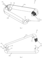
- the bracket 101 has a first longitudinal member 110a and a second longitudinal member 110b.
- the longitudinal elements 110a, 110b are connected to one another at a respective first end by an end section 140 in a movable (articulated) manner.
- the longitudinal elements 110a, 110b have a cross section which corresponds to 1/4 of an ellipse, the inner sides of the longitudinal elements 110a, 110b being flat and aligned with one another.
- the end section 140 is prestressed so that the clamp 101 is in an open state without the application of external force.
- the bias of the end portion 140 provides an angle between the first longitudinal member 110a and the second longitudinal member 110b.
- the angle between the first and second longitudinal members 110a, 110b is preferably between 6° and 30° and more preferably between 12° and 15°.
- the two longitudinal elements 110a, 110b are essentially parallel to one another when the clamp 101 is in a closed state.
- the longitudinal members are provided with an inward vertical protrusion of about 0.3 mm to better fit the longitudinal members to the edge portion.
- the end section 140 also has a T-shaped recess 150 for stress reduction and for compensating for production tolerances.
- the T-shaped recess 150 is centered in the end section 140 .
- the T-shaped recess 150 divides the end portion 140 into two equal parts by a first recess which is in a closed state of the Clamp 101 extends parallel to the longitudinal elements 110a, 110b.
- the T-shaped cavity 150 further includes a second cavity disposed substantially perpendicular to the first cavity, with the first cavity being disposed substantially centrally of the second cavity.
- the second recess has a curvature in the direction of the first recess (in the direction of the longitudinal elements 110a, 110b).
- the clip 101 also has four retaining segments 131-134.
- the first holding segment 131 and the second holding segment 132 are arranged on an inside of the end section 140 and an inside of the respective longitudinal elements 110a, 110b.
- the first holding segment 131 and the second holding segment 132 protrude into the clamp opening.
- the first holding segment 131 and the second holding segment 132 are preferably of the same length and preferably have a lower height than the longitudinal elements 110a, 110b and the end section.
- the height of the first holding segment 131 and the second holding segment 132 gradually increases in the direction of the end section 140 and gradually decreases in the direction of the interior of the clip 101, respectively.
- the third holding segment 133 and the fourth holding segment 134 are arranged at the opposite end of the longitudinal elements 110a, 110b.
- the height of the third holding segment 133 and the fourth holding segment 134 increases towards the closure element 120 and gradually decreases towards the interior of the clip 101 (not shown in the figures).
- the third holding segment 133 protrudes further into the interior of the clamp 101 than the fourth holding segment 134.
- the clamp 101 also has a closure element 120 at the end of the longitudinal elements 110a, 110b opposite the end section 140.
- the closure element 120 has a first closure element 121 and a second closure element 122 .
- the first closure element 121 has a U-shaped bracket 123 .
- the second closure element 122 has a corresponding bulge 124 .
- the U-shaped bracket 123 is arranged on the first longitudinal member 110a and opens to the inside of the first longitudinal member 110a.
- the bulge 124 is formed to be received in the opening of the U-shaped bracket 123 .
- the U-shaped bracket 123 has an inward projection at one end of one of its legs.
- the second closure element 122 also has a recess into which the projection of the U-shaped bracket 123 can engage in order to hold the clip 101 in a closed state.
- the first closure element 121 can also have a grip element on its upper side.
- the grip element can have a plurality of grooves (a groove structure) arranged in parallel.
- the third and fourth holding segment 133, 134 is arranged both on the longitudinal elements 110a, 110b and on the closure elements 121, 122.
- the longitudinal elements 110a, 110b, the end section 140 and the closure element 120 have an essentially uniform height and are rounded upwards, whereby according to one embodiment a horizontal protrusion of the longitudinal elements in the longitudinal direction by approx. 0.6 mm can be provided.
- the clamp 101 in the closed state has a through opening which is formed by the longitudinal elements 110a, 110b, the end section 140 and the closure element 120.
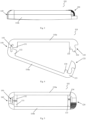
- the second embodiment differs from the first embodiment in the shape of the longitudinal elements 110a, 110b, the end section 140 and the closure element 120.
- the longitudinal elements 110a, 110b, the end section 140 and the closure element 120 according to the second embodiment have a rectangular shape.
- the longitudinal elements 110a, 110b, the end section 140 and the closure element 120 according to the second embodiment are not rounded upwards as in the first embodiment but are formed with surfaces perpendicular to one another.
- the third embodiment differs from the first embodiment in the shape of the longitudinal elements 110a, 110b, the end section 140 and the closure element 120.
- the longitudinal elements 110a, 110b, the end section 140 and the closure element 120 according to the third embodiment have a trapezoidal shape.
- the longitudinal elements 110a, 110b, the end section 140 and the closure element 120 according to the third embodiment are not rounded upwards as in the first embodiment but are formed with straight surfaces which are each formed at an angle ( ⁇ 90°) to one another .
- the longitudinal elements 110a, 110b have two vertical side surfaces, a horizontal lower surface and a horizontal upper surface.
- the horizontal lower surface connects the side surfaces at an angle of 90°.
- the side face lying outward is shorter towards the top than the side face lying inward.
- the horizontal upper surface is connected directly to the inner side surface at an angle of 90°.
- a sloping surface connects the shorter side surface with the horizontal top.
- a corresponding longitudinal element thus forms a trapezium in cross section.
- the fourth embodiment is shown in accordance with the shape of the first embodiment, i.e. the longitudinal elements 110a, 110b, the end section 140 and the closure element 120 are rounded upwards, the configurations described with reference to the second and third embodiments (rectangular and trapezoidal) are also applicable to the fourth embodiment transferrable.
- the fourth embodiment differs from the first embodiment essentially in the design or alignment of the closure element 120 .
- the fourth embodiment also has a first closure element 121 and a second closure element 122 .
- the first closure element 121 has a U-shaped bracket 125 and the second closure element 122 has a corresponding bulge 126 .
- the U-shaped bracket 125 of the fourth embodiment is arranged on the first longitudinal member 110a.
- the U-shaped bracket 125 of the fourth embodiment is open to the inside of the bracket 104 .
- the opening of the U-shaped bracket 125 of the fourth embodiment is formed parallel to the longitudinal direction of the first longitudinal member 110a.
- the opening of the U-shaped bracket 123 is formed perpendicular to the longitudinal direction of the first longitudinal member 110a.
- the bulge 126 is formed to be received in the opening of the U-shaped bracket 125 .
- the U-shaped bracket 125 has an inward projection at one end of one of its legs.
- the second closure element 122 also has a recess into which the projection of the U-shaped bracket 125 can engage in order to hold the clip 104 in a closed state.
- the fourth embodiment differs from the first embodiment in the orientation of the first and second closure element 121, 122. Furthermore, the closure of the fourth embodiment is visible in the installed state.
- the fourth embodiment has an additional element that makes it possible to pull or push the tear over the bulge.
- This additional element can be a recess for fingernails, for example.
- the opening thus includes the further step of pulling or pushing the tear over the bulge.
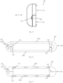
- a fifth embodiment of a clamp 105 according to the invention is explained in more detail below.
- the above statements on the first embodiment essentially also apply to the fifth embodiment. Only the differences from the first embodiment are described below in order to avoid unnecessary repetition.
- the fifth embodiment is shown in accordance with the shape of the first embodiment, ie the longitudinal elements 110a, 110b, the end portion 140 and the closure element 120 are rounded upwards, the configurations described with reference to the second and third embodiments (rectangular and trapezoidal) are also applicable to the fifth embodiment transferrable.
- the fifth embodiment differs from the first embodiment essentially in the design of the closure element 120.
- the closure element has a first closure element 121 and a second closure element 122 .
- the first closure element 121 has a recess 127 on an underside.
- the second closure element 122 has a corresponding bulge 128 on an upper side.
- the recess 127 and the bulge 128 are formed on the face of the clip 105 and the face of the closure member 120, respectively, and are configured to interlock to hold the clip 105 in a closed condition.
- the bulge 128 has a first gradient in the direction of the second longitudinal element 110b and a second gradient in the direction of the first longitudinal element 110a, the first gradient being greater (steeper) than the second gradient.
- the recess 127 is formed in correspondence.
- This configuration facilitates the closure of the clip 105 with little resistance from the bulge 128 when the first closure member 121 is moved over the second closure member 122 for closure.
- the closing force is increased due to the steeper incline on the other side of the bulge 128 , since greater effort is required to move the first closure element 121 over the second closure element 122 to open the clamp 105 .
- the sixth embodiment is shown in accordance with the shape of the first embodiment, i.e. the longitudinal elements 110a, 110b, the end section 140 and the closure element 120 are rounded upwards, the configurations (rectangular and trapezoidal) described with reference to the second and third embodiments are also applicable to the sixth embodiment transferrable.
- the sixth embodiment differs from the first embodiment essentially in the design of the closure element 120.
- the closure member 120 of the sixth embodiment has a recess (not shown) on the underside of the first Closure element 121 and a bulge 128a on top of the second closure element 122.
- the recess on the bottom of the first locking member 121 is formed such that the bulge 128a can also receive the top of the second locking member 122 to hold the clip 106 in a closed state.
- the recess and the bulge 128a are each at a distance from the edges of the first and second closure elements 121, 122.
- the bulge 128a has a first slope in the direction of the second longitudinal element 110b and a second slope in the direction of the first longitudinal element 110a, the first slope being equal to the second slope.
- the recess on the underside of the first closure element 121 is formed in correspondence.
- This configuration provides a uniform resistance when closing and when opening.
- the edge section 11 has an indentation 12a, 12b on opposite end regions.
- the first component 10 is preferably a plate element which extends over a surface area and has a thickness D.
- the first component 10 extends areally in two spatial directions by a first length L 1 and a first width B 1 .
- the component also has a thickness D in a third spatial direction, the length L 1 and the width B 1 >> than the thickness D.
- the spatial directions mentioned above are each perpendicular to one another.
- the edge portion 11 extends from an end portion of the first structural element 10 and has a second length L 2 and a second width B 2 , where preferably L 1 > L 2 and B 1 > B 2 .
- the thickness of the edge section 11 is preferably equal to the thickness D of the first component 10.
- the lengths L 1 , L 2 mentioned above are not necessarily provided in this ratio. Rather, the second length can be L 2 ⁇ L 1 . Furthermore, the thickness of the edge section 11 can be different from the thickness D of the first component 10 .
- the dents 12a, 12b are provided at the end portions of the skirt portion 11 in the width direction and are preferably rounded, that is, the dents 12a, 12b are preferably provided in a round shape.
- the indentations 12a, 12b can, as in 21 shown, may be provided at a certain distance up and down (in the lengthwise direction L 2 ) from the edge portion 11 .
- the indentations 12a, 12b can be provided at the lower end (in the longitudinal direction L 2 ), ie the indentations 12a, 12b can extend directly from the end area of the first component 10.
- Both the rounded shape of the indentations 12a, 12b and the rounded shape of the holding segments 131-134 described above ensure that the holding segments 131-134 can be easily introduced into the indentations 12a, 12b.
- the indentations 12a, 12b also extend so far in the longitudinal direction of the edge section 11 that the indentations 12a, 12b protrude at least partially through a slot, described in more detail below, of a second component.
- the 22 shows a second component 20 with a slot 21.
- the component 20 has a length L 3 and a width B 3 on.
- the slot 21 has a length L 4 and a width B 4 , where L 3 >L 4 and B 3 >B 4 .
- the length L 4 of the elongated hole 21 is greater than the width B 2 of the edge portion 11 and the width B 4 of the elongated hole 21 is greater than the thickness of the edge portion 11 (see description of the edge portion according to 21 ), so that the edge section 11 can be passed through the elongated hole 21.
- the length L 4 of the slot 21 is less than the width B 1 of the first component 10 so that only the edge section 11 can protrude through the slot 21 .
- the first component 10 can also have an elongated hole next to the edge section 11 and the second component 20 can also have an edge section next to the elongated hole 21 . Furthermore, the first component 10 and/or the second component 20 can have a plurality of edge sections and/or slots.
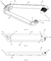
- FIG. 24 shows a state according to 23 from another perspective, that is, a state in which the edge portion 11 has been inserted through the elongated hole 21.
- FIG. Additionally shows 24 a clip 101 attached to the edge portion in an opened state.
- the clip 101 is placed on the edge portion 11 of the first structural element 10 and the holding segments 131, 132 and 133 are placed in the indentations 12a, 12b.
- the clip 101 is then closed by guiding the first closure element 121 over the second closure element 122 and thus also bringing the holding segment 134 into engagement with the corresponding indentation.
- a force is exerted on the retaining segments 131-134 by the indentations 12a, 12b and the clip 101 is retained in position.
- the closed state of clamp 101 is in 25 shown.
- the clamp 101 can be opened again by an external force, in that the first closure element 121 is pushed away from the second closure element 122 .
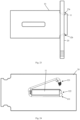
- FIG. 26 shows an exemplary modular shelving system 201 consisting of a plurality of panel elements which are designed with one or more edge sections 11 or elongated holes 21 as described above.
- the brackets (not shown) described above are used to secure the various panel members.
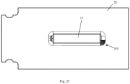
- FIG. 27 shows an exemplary roll box 202 consisting of several plate elements, which are designed with one or more edge sections 11 or elongated holes 21 as described above.
- the brackets (not shown) described above are used to secure the various panel members. Additional wheels are attached to the underside of the roll box.
- the application systems Figures 26 and 27 are merely exemplary and can be provided in various configurations using the invention. Further exemplary application systems relate to furniture systems, organization or storage systems, point-of-sale displays, furniture systems or housing for pets, picture frames or transport packaging.
- Furniture systems or shelters for pets include various commodities used in connection with pets inside or outside apartments and houses, such as sleeping places, play equipment and scratching posts, etc.
- the bracket 101 is only an example in the Figures 24-25 shown. It should be clear that all of the clips 101-106 described above can be used for fastening the first panel member 10 and the second panel member 20 in the same way.
Landscapes
- Engineering & Computer Science (AREA)
- General Engineering & Computer Science (AREA)
- Mechanical Engineering (AREA)
- Clamps And Clips (AREA)
Description
Die vorliegende Erfindung bezieht sich auf ein System zum lösbaren Verbinden von Bauelementen insbesondere zum lösbaren Verbinden von Bauelementen z.B. eines Möbelsystems, eines Ordnungs- oder Aufbewahrungssystems, eines Point-of-Sale-Displays, eines Möbelsystems oder einer Unterkunft für Haustiere, eines Bilderrahmens oder einer Transportverpackung.The present invention relates to a system for the detachable connection of components, in particular for the detachable connection of components, e.g transport packaging.
Aus dem Stand der Technik sind Bausätze z.B. für Möbelsysteme bekannt, die zum lösbaren Verbinden der verschiedenen Elemente elastische Gummibänder bzw. Gummiringe verwenden.Kits, e.g. for furniture systems, are known from the prior art, which use elastic rubber bands or rubber rings to detachably connect the various elements.
Beispielsweise bezieht sich die
Ferner bezieht sich die
Aus der
Der vorliegenden Erfindung liegt die Aufgabe zugrunde, Systeme und Verfahren bereitzustellen, die eine stabile, einfache und langlebige lösbare Verbindung von Bauelementen ermöglicht.The present invention is based on the object of providing systems and methods that enable a stable, simple and durable detachable connection of components.
Diese Aufgabe wird mit den Merkmalen der unabhängigen Patentansprüche gelöst. Die abhängigen Patentansprüche beziehen sich auf weitere Aspekte der Erfindung.This object is achieved with the features of the independent patent claims. The dependent claims relate to further aspects of the invention.
Gemäß einem Aspekt der vorliegenden Erfindung wird ein System mit mindestens einem ersten Bauelement, insbesondere einem ersten Plattenelement, und mindestens einem zweiten Bauelement, insbesondere einem zweiten Plattenelement, bereitgestellt. Das erste Bauelement weist mindestens einen vorstehenden Randabschnitt auf, wobei der Randabschnitt an seinen entgegengesetzten Endbereichen jeweils eine Einbuchtung aufweist und das zweite Bauelement mindestens ein Langloch aufweist, wobei der Randabschnitt das Langloch in einem zusammengebauten Zustand durchdringt und mindestens so weit aus dem Langloch herausragt, dass die Einbuchtungen zumindest teilweise aus dem Langloch herausragen. Das System weist ferner mindestens eine Klammer auf, um die Bauelemente lösbar miteinander zu verbinden. Die Klammer weist auf zwei Längselemente mit jeweils einem ersten und einem zweiten Ende, wobei die zwei Längselemente an dem jeweiligen ersten Ende beweglich miteinander verbunden sind; ein Verschlusselement, das an dem zweiten Ende mindestens eines Längselements vorgesehen ist, wobei das Verschlusselement konfiguriert ist, die zweiten Enden der Längselemente lösbar zu verbinden; und mindestens zwei Haltesegmente, die in gegenüberliegenden Endbereichen der Längselemente vorgesehen sind und konfiguriert sind, jeweils mit den Einbuchtungen des Randabschnitts des ersten Bauelements in Eingriff gebracht zu werden und die Bauelemente lösbar miteinander zu verbinden.According to one aspect of the present invention, a system is provided with at least one first component, in particular a first panel element, and at least one second component, in particular a second panel element. The first component has at least one protruding edge section, the edge section having an indentation in each of its opposite end regions and the second component has at least one slot, the edge section penetrating the slot in an assembled state and protruding at least so far out of the slot that the indentations protrude at least partially out of the slot. The system also includes at least one clip to releasably connect the components together. The clip comprises two longitudinal members each having a first end and a second end, the two longitudinal members being movably connected to each other at the respective first end; a fastener provided at the second end of at least one longitudinal member, the fastener being configured to releasably connect the second ends of the longitudinal members; and at least two retaining segments provided in opposite end portions of the longitudinal members and configured to be respectively engaged with the indentations of the edge portion of the first structural member and releasably connect the structural members together.
Die vorstehend genannten Enden (erstes und zweites Ende) der Längselemente sind in Längsrichtung der Längselemente ausgebildet.The above ends (first and second ends) of the longitudinal members are formed in the longitudinal direction of the longitudinal members.
Die vorstehend genannten Endbereiche der Längselemente sind ebenfalls in Längsrichtung der Längselemente ausgebildet.The aforementioned end portions of the longitudinal members are also formed in the longitudinal direction of the longitudinal members.
Die Längselemente können eine horizontale Wölbung (Vorwölbung) in Längsrichtung aufweisen. Die Wölbung beträgt vorzugsweise 0,6 mm.The longitudinal elements can have a horizontal curvature (protrusion) in the longitudinal direction. The curvature is preferably 0.6 mm.
Dadurch können Produktionstoleranzen, speziell im Bereich des Randabschnitts und insbesondere im Bereich der Einbuchtungen, überbrückt werden.As a result, production tolerances, especially in the area of the edge section and in particular in the area of the indentations, can be bridged.
Ferner kann die Langlebigkeit der Bauelemente, speziell im Bereich des Randabschnitts und insbesondere im Bereich der Einbuchtungen, erhöht werden. Insbesondere indem die Vorwölbung Stöße "abfedert" und somit die Einbuchtungen vor Abnutzung schützt.Furthermore, the longevity of the components, especially in the area of the edge section and in particular in the area of the indentations, can be increased. In particular, the protrusion "cushions" shocks and thus protects the indentations from wear.
Die mindestens zwei Haltesegmente werden vorzugsweise mit den Einbuchtungen des Randabschnitts des ersten Bauelements in Eingriff gebracht, wenn der Randabschnitt das Langloch durchdringt.The at least two holding segments are preferably brought into engagement with the indentations of the edge section of the first component when the edge section penetrates the elongated hole.
Die mindestens zwei Haltesegmente können eine maximale erste Höhe und das erste und/oder zweite Längselement eine minimale zweite Höhe aufweisen, wobei die erste Höhe geringer als die zweite Höhe ist.The at least two retaining segments can have a maximum first height and the first and/or second longitudinal element can have a minimum second height, the first height being less than the second height.
Die jeweilige Höhe der mindestens zwei Haltesegmente und der Längselemente kann eine Ausdehnung der Elemente senkrecht zur Richtung vom ersten zum zweiten Ende der Längselemente und senkrecht zu einer Richtung von dem ersten Ende des ersten Längselements zu dem mit diesem verbundenen ersten Ende des zweiten Längselements bezeichnen.The respective height of the at least two holding segments and the longitudinal elements can denote an extension of the elements perpendicular to the direction from the first to the second end of the longitudinal elements and perpendicular to a direction from the first end of the first longitudinal element to the first end of the second longitudinal element connected thereto.
Mit anderen Worten, die Richtung der jeweiligen Höhen kann senkrecht zu der Ebene stehen, in der die beiden Längselemente liegen.In other words, the direction of the respective heights can be perpendicular to the plane in which the two longitudinal elements lie.
Mit anderen Worten, die mindestens zwei Haltesegmente weisen vorzugsweise eine geringere Höhe als das erste und/oder zweite Längselement auf.In other words, the at least two holding segments preferably have a lower height than the first and/or second longitudinal element.
Durch diese Konfiguration kann erreicht werden, dass das erste und/oder zweite Längselement zumindest teilweise über die Haltesegmente, die in die Einbuchtungen eingreifen, hinausragen, um den Randabschnitt vor äußeren Einflüssen zu schützen und die Stabilität der Konstruktion, bedingt durch eine höhere Steifigkeit der formschlüssigen Verbindung, zu erhöhen.This configuration makes it possible for the first and/or second longitudinal element to protrude at least partially beyond the holding segments, which engage in the indentations, in order to protect the edge section from external influences and improve the stability of the construction due to greater rigidity of the form-fitting connection to increase.
Die erste Höhe kann einer Höhe (bzw. Länge) entsprechen, um die die Einbuchtungen aus dem Langloch herausragen. Mit anderen Worten, die Höhe der Haltesegmente kann einer Höhe entsprechen, um die die Einbuchtungen aus dem Langloch herausragen. Somit kann ein formschlüssiger Eingriff der Haltesegmente in die Einbuchtungen erreicht werden und die Stabilität der Konstruktion, bedingt durch eine höhere Steifigkeit der formschlüssigen Verbindung, erhöht werden.The first height can correspond to a height (or length) by which the indentations protrude from the elongated hole. In other words, the height of the holding segments can correspond to a height by which the indentations protrude from the slot. In this way, a form-fitting engagement of the holding segments in the indentations can be achieved and the stability of the construction can be increased due to the greater rigidity of the form-fitting connection.
Die Klammer kann ferner aufweisen: einen Endabschnitt, der konfiguriert ist, die beiden Längselemente beweglich, vorzugsweise gelenkig, zu verbinden.The clip may further include: an end portion configured to movably, preferably hingedly, connect the two longitudinal members.
Der Endabschnitt und/oder das Verschlusselement kann eine minimale dritte Höhe aufweisen, wobei die erste Höhe geringer als die dritte Höhe ist. Mit anderen Worten, die mindestens zwei Haltesegmente weisen vorzugsweise eine geringere Höhe als der Endabschnitt und/oder das Verschlusselement auf.The end section and/or the closure element can have a minimum third height, the first height being less than the third height. In other words, the at least two holding segments preferably have a lower height than the end section and/or the closure element.
Die dritte Höhe kann eine Ausdehnung der Elemente senkrecht zur Richtung vom ersten zum zweiten Ende der Längselemente und senkrecht zu einer Richtung von dem ersten Ende des ersten Längselements zu dem mit diesem verbundenen ersten Ende des zweiten Längselements bezeichnen.The third height may denote an extension of the elements perpendicular to the direction from the first to the second end of the longitudinal elements and perpendicular to a direction from the first end of the first longitudinal element to the first end of the second longitudinal element connected thereto.
Durch diese Konfiguration kann erreicht werden, dass der Endabschnitt und/oder das Verschlusselement zumindest teilweise über die Haltesegmente, die in die Einbuchtungen eingreifen, hinausragen, um den Randabschnitt vor äußeren Einflüssen zu schützen und die Stabilität der Konstruktion, bedingt durch eine höhere Steifigkeit der formschlüssigen Verbindung, zu erhöhen.This configuration makes it possible for the end section and/or the closure element to protrude at least partially beyond the retaining segments that engage in the indentations, in order to protect the edge section from external influences and improve the stability of the construction due to the higher rigidity of the form-fitting connection to increase.
Die zweite Höhe kann im Wesentlichen gleich der dritten Höhe sein. Mit anderen Worten, die Höhe des ersten und/oder zweiten Längselements kann gleich der Höhe des Endabschnitts und/oder des Verschlusselements sein.The second height may be substantially equal to the third height. In other words, the height of the first and/or second longitudinal element can be equal to the height of the end portion and/or the closure element.
Die zweite und/oder dritte Höhe kann mindestens der Länge entsprechen, die der Randabschnitt aus dem Langloch herausragt. Somit kann der Randabschnitt von den entsprechenden Elementen vor äußeren Einflüssen geschützt werden und gleichzeitig die Stabilität der verbundenen Bauelemente, bedingt durch eine höhere Steifigkeit der formschlüssigen Verbindung, erhöht werden.The second and/or third height can correspond at least to the length by which the edge section protrudes from the elongated hole. Thus, the edge portion can be protected by the corresponding elements from external influences and at the same time Stability of the connected components, due to a higher rigidity of the form-fitting connection, can be increased.
Es ist vorteilhaft, dass die zweite und dritte Höhe mindestens der Länge entsprechen, die der Randabschnitt aus dem Langloch herausragt. Mit anderen Worten, es ist besonders vorteilhaft, wenn die Längselemente, der Endabschnitt und das Verschlusselement mindestens der Länge entsprechen, die der Randabschnitt aus dem Langloch herausragt. Dies erzeugt einen erhöhten Schutz des Randabschnitts und eine erhöhte Stabilität der Konstruktion, bedingt durch eine höhere Steifigkeit der formschlüssigen Verbindung.It is advantageous for the second and third heights to correspond at least to the length by which the edge section protrudes from the elongated hole. In other words, it is particularly advantageous if the longitudinal elements, the end section and the closure element correspond at least to the length by which the edge section protrudes from the slot. This creates increased protection of the edge section and increased stability of the construction, due to a higher rigidity of the form-fitting connection.
Allerdings wird ein gewisser Schutz und/oder eine gewisse Stabilität bereits durch eine entsprechende Höhe (mindestens der Länge, die der Randabschnitt aus dem Langloch herausragt) mindestens eines der vorstehend genannten Elementen (Längselement, Endabschnitt und Verschlusselement) erzielt. Beispielsweise kann eine Seite des Randabschnitts, der besonders äußeren Einflüssen ausgesetzt ist, nur an dieser Seite durch ein erhöhtes Element, z.B. ein Längselement, geschützt sein, wobei die anderen Elemente eine geringere Höhe aufweisen. Somit kann bei erhöhtem Schutz vor äußeren Einflüssen, der Materialbedarf gesenkt werden.However, a certain protection and/or a certain stability is already achieved by a corresponding height (at least the length by which the edge section protrudes from the elongated hole) of at least one of the aforementioned elements (longitudinal element, end section and closure element). For example, one side of the edge portion that is particularly exposed to external influences may be protected only on that side by a raised element, for example a longitudinal element, the other elements being of reduced height. Thus, with increased protection against external influences, the material requirements can be reduced.
Der Endabschnitt und/oder das Verschlusselement und/oder die zwei Längselemente kann/können mit dem Randabschnitt, der durch das Langloch ragt, (im zusammengebauten Zustand) bündig abschließen, wobei vorzugsweise der Endabschnitt, das Verschlusselement und die zwei Längselemente mit dem Randabschnitt, der durch das Langloch ragt, bündig abschließen.The end section and/or the closure element and/or the two longitudinal elements can/can be flush with the edge section that protrudes through the slot (in the assembled state), with preferably the end section, the closure element and the two longitudinal elements with the edge section that protrudes through the long hole, finish flush.
Der Randabschnitt kann dabei verschieden ausgebildete Endabschnitte aufweisen. Beispielsweise kann der Endabschnitt des Randabschnitts eben ausgebildet sein, d.h. der Endabschnitt steht in einem rechten Winkel auf den Seitenflächen des Randabschnitts und ist im Wesentlichen eben ausgebildet. In diesem Fall, ist es bevorzugt, dass die vorstehend genannten Elemente der Klammer (Endabschnitt, Verschlusselement und Längselement) mit dem eben ausgebildeten Endabschnitt des Randabschnitts bündig abschließen.The edge section can have differently designed end sections. For example, the end portion of the rim portion may be planar, i.e. the end portion is at right angles to the side faces of the rim portion and is substantially planar. In this case, it is preferred that the above-mentioned elements of the clip (end section, closure element and longitudinal element) are flush with the planar end section of the edge section.
Alternativ kann der Randabschnitt einen trapezförmig ausgebildeten Endabschnitt aufweisen. In diesem Fall umfasst der Endabschnitt erste Flächen, die unter einem Winkel an den Seitenflächen des Randabschnitts angebracht sind, und eine zweite Fläche, die im Wesentlichen einen rechten Winkel zu den Seitenflächen des Randabschnitts aufweist und die ersten Flächen verbindet. In dieser Ausführungsform können die vorstehend genannten Elemente der Klammer (Endabschnitt, Verschlusselement und Längselement) vorzugsweise an der Anschlussstelle der ersten Flächen und der Seitenflächen des Randabschnitts bündig abschließen.Alternatively, the edge section can have a trapezoidal end section. In this case, the end portion comprises first faces attached at an angle to the side faces of the rim portion and a second face which is substantially at right angles to the side faces of the rim portion and connects the first faces. In this embodiment, the above-mentioned elements of the clip (end section, closure element and longitudinal element) can preferably end flush at the connection point of the first surfaces and the side surfaces of the edge section.
Alternativ können die vorstehend genannten Elemente der Klammer (Endabschnitt, Verschlusselement und Längselement) in dieser Ausführungsform an der Anschlussstelle der zweiten Fläche und der ersten Flächen bündig abschließen.Alternatively, in this embodiment, the aforementioned elements of the clip (end portion, closure element, and longitudinal element) may be flush at the junction of the second surface and the first surfaces.
In einer bevorzugten Ausführungsform kann der Randabschnitt einen abgerundet ausgebildeten Endabschnitt aufweisen. In dieser Ausführungsform können die vorstehend genannten Elemente der Klammer (Endabschnitt, Verschlusselement und Längselement) vorzugsweise an der Anschlussstelle des abgerundeten Endabschnitts und der Seitenflächen des Randabschnitts bündig abschließen.In a preferred embodiment, the edge section can have a rounded end section. In this embodiment, the above-mentioned elements of the clip (end section, closure element and longitudinal element) can preferably end flush at the connection point of the rounded end section and the side surfaces of the edge section.
Alternativ können die vorstehend genannten Elemente der Klammer (Endabschnitt, Verschlusselement und Längselement) in dieser Ausführungsform an einer vorbestimmten Stelle des abgerundeten Endabschnitts bündig abschließen.Alternatively, in this embodiment, the above-mentioned elements of the clip (end portion, closure element and longitudinal element) can be flush at a predetermined point of the rounded end portion.
Das bündige Abschließen der vorstehend genannten Elemente der Klammer (Endabschnitt, Verschlusselement und Längselement) und dem Randabschnitt bietet einen hohen Schutz vor äußeren Einflüssen des Randabschnitts und einen gleichzeitig hohen Schutz der entsprechenden Elemente der Klammer, da diese nicht über den Randabschnitt hinausragen und somit vor beispielsweise Abbrechen oder ungewolltem Öffnen bzw. Lösen geschützt sind.The flush termination of the aforementioned elements of the clamp (end section, closure element and longitudinal element) and the edge section offers a high level of protection against external influences of the edge section and at the same time a high level of protection of the corresponding elements of the clamp, since they do not protrude beyond the edge section and thus against, for example Break off or unintentional opening or loosening are protected.
Mindestens ein Haltesegment kann mit dem Endabschnitt und mindestens ein Haltesegment kann mit dem Verschlusselement verbunden sein.At least one retaining segment can be connected to the end section and at least one retaining segment can be connected to the closure element.
Alternativ oder zusätzlich können die Haltesegmente mit den Längselementen verbunden sein.Alternatively or additionally, the holding segments can be connected to the longitudinal elements.
Die mindestens zwei Haltesegmente können vier Haltesegmente aufweisen, die vorzugsweise gegenüberliegend in den jeweiligen Endbereichen der Längselemente angeordnet sind.The at least two holding segments can have four holding segments, which are preferably arranged opposite one another in the respective end regions of the longitudinal elements.
Die gegenüberliegenden Haltesegmente können gleich lang oder unterschiedlich lang ausgebildet sein und vorzugsweise in einem geschlossenen Zustand der Klammer in Berührung kommen oder einen geringen Abstand aufweisen.The opposing holding segments can be of the same length or of different lengths and preferably come into contact in a closed state of the clamp or have a small distance.
Durch einen geringen Abstand der Haltesegmente, besonders bevorzugt 0,3 mm, kann eine erhöhte Stabilität sowie eine vorteilhafte Berücksichtigung von Fertigungstoleranzen erreicht werden.A small distance between the holding segments, particularly preferably 0.3 mm, allows increased stability and advantageous consideration of manufacturing tolerances to be achieved.
Das Verschlusselement kann auf einer Oberseite eine Mehrzahl an Rillen, vorzugsweise parallel angeordnete Rillen, aufweisen.The closure element can have a plurality of grooves, preferably parallel grooves, on an upper side.
Die Rillen können durch Ausbuchtungen auf der Oberseite des Verschlusselements ausgebildet werden. Alternativ kann die Oberfläche mit Vertiefungen ausgebildet werden.The grooves can be formed by bulges on the upper side of the closure element. Alternatively, the surface can be formed with indentations.
Die Rillen erhöhen die Griffigkeit der Klammer und erleichtern so das Öffnen und Schließen der Klammer.The grooves increase the grip of the clip, making it easier to open and close the clip.
Das Verschlusselement kann ein erstes Verschlusselement und ein zweites Verschlusselement aufweisen, die formschlüssig zusammenwirken können.The closure element can have a first closure element and a second closure element, which can interact in a form-fitting manner.
Das erste Verschlusselement kann einen U-förmigen Bügel aufweisen und das zweite Verschlusselement kann eine Ausbuchtung aufweisen, die mit dem U-förmigen Bügel verschließbar zusammenwirken kann.The first closure element can have a U-shaped bracket and the second closure element can have a bulge which can interact in a lockable manner with the U-shaped bracket.
Der U-förmige Bügel kann einen Überriss und eine Ausnehmung aufweisen.The U-shaped bracket can have an overhang and a recess.
Diese Art von Ausgestaltung der Verschlusselemente ermöglicht einen Verschluss, der im verbauten Zustand nicht sichtbar ist. Ferner wird die gleiche Kraft für das Öffnen wie für das Schließen benötigt, unabhängig von Fertigungstoleranzen im Bereich des Randabschnittes, insbesondere im Bereich der Ausbuchtungen. Durch Aufschieben des Verschlusselements kann die Klammer einfach und komfortabel geöffnet werden.This type of configuration of the closure elements enables a closure that is not visible in the installed state. Furthermore, the same force is required for opening as for closing, regardless of manufacturing tolerances in the area of the edge section, particularly in the area of the bulges. The clip can be opened easily and conveniently by sliding the locking element open.
Die Klammer, insbesondere das Verschlusselement der Klammer, kann ferner konfiguriert sein, dass die Klammer nur geschlossen bleibt, wenn die Klammer mit dem Randabschnitt, insbesondere den Einbuchtungen des Randabschnitts, in Eingriff steht.The clip, in particular the closure element of the clip, can also be configured such that the clip only remains closed when the clip is in engagement with the edge section, in particular the indentations of the edge section.
Mit anderen Worten, die Klammer, insbesondere das Verschlusselement der Klammer, kann konfiguriert sein, dass durch den Randabschnitt, insbesondere die Einbuchtungen des Randabschnitts, eine Kraft auf das Verschlusselement wirkt, die einen dauerhaften Verschluss der Klammer bewirkt. Dieser Verschluss kann vorzugsweise nur mit einer gewissen Kraftaufwendung durch einen Nutzer geöffnet werden.In other words, the clip, in particular the closure element of the clip, can be configured such that a force acts on the closure element through the edge section, in particular the indentations of the edge section, which force causes a permanent closure of the clamp. This closure can preferably only be opened by a user with a certain application of force.
Weist das erste Verschlusselement beispielsweise eine Vertiefung auf seiner Unterseite auf und das zweite Verschlusselement eine entsprechende Ausbuchtung auf seiner Oberseite auf, die mit der Vertiefung verschließbar zusammenwirken kann, wird durch den Randabschnitt, insbesondere die Einbuchtungen des Randabschnitts, eine bestimmte Kraft auf das/die Haltesegment/Haltesegmente ausgeübt. Diese Krafteinwirkung drückt die Vertiefung des ersten Verschlusselements auf die Ausbuchtung des zweiten Verschlusselements und hält die Klammer somit in einem geschlossenen Zustand.If the first closure element has, for example, a recess on its underside and the second closure element has a corresponding bulge on its upper side, which can interact in a closable manner with the recess, the edge section, in particular the indentations of the edge section, exerts a certain force on the holding segment(s). / hold segments exercised. This action of force presses the indentation of the first closure element onto the bulge of the second closure element and thus holds the clip in a closed state.
Mit anderen Worten, das erste Verschlusselement kann eine Vertiefung auf seiner Unterseite aufweisen. Das zweite Verschlusselement kann eine Ausbuchtung auf seiner Oberseite aufweisen, die mit der Vertiefung verschließbar zusammenwirken kann.In other words, the first closure element can have a recess on its underside. The second closure element can have a bulge on its upper side, which can interact with the depression in a closable manner.
Die Unterseite des ersten Verschlusselements kann eine der Oberseite des zweiten Verschlusselements zugewandte Fläche sein.
Auch diese Art der Ausgestaltung der Verschlusselemente ermöglicht einen Verschluss, der im verbauten Zustand nicht sichtbar ist. Durch eine geeignete Auswahl der vorstehend genannten Fertigungstoleranzen der Ausbuchtungen ist die zum Öffnen und Schließen der Klammer benötigte Kraft einstellbar.The bottom of the first closure member may be a surface facing the top of the second closure member.
This type of configuration of the closure elements also enables a closure that is not visible in the installed state. The force required to open and close the clip can be adjusted by suitably selecting the aforementioned manufacturing tolerances for the bulges.
Die Klammer ist vorzugsweise einstückig ausgebildet.The clip is preferably formed in one piece.
Der Endabschnitt weist vorzugsweise eine T-förmige Ausnehmung auf. Die T-förmige Ausnehmung kann die Spannung beim Schließen und Öffnen an der geschlossenen Seite (Endabschnitt) der Klammer reduzieren. Ferner können Fertigungstoleranzen des Randabschnitts (bezogen auf die Länge) ausgeglichen werden, da sich die innen angrenzenden Elemente der T-förmigen Ausnehmung nach außen verdrängen lassen.The end section preferably has a T-shaped recess. The T-shaped recess can reduce the stress when closing and opening at the closed side (end portion) of the clip. Furthermore, manufacturing tolerances of the edge section (in relation to the length) can be compensated for, since the elements of the T-shaped recess that border on the inside can be displaced outwards.
Die bewegliche Verbindung der zwei Längselemente kann eine Vorspannung aufweisen, so dass sich das Verschlusselement ohne äußere Krafteinwirkung in einem geöffneten Zustand befindet. Hierdurch kann die Handhabbarkeit der Klammer erhöht werden.The moveable connection of the two longitudinal elements can have a pretension, so that the closure element is in an open state without the action of an external force. As a result, the handling of the clip can be increased.
Die Längselemente und/oder der Endabschnitt und/oder das Verschlusselement können einen Querschnitt entsprechend eines Rechtecks, vorzugsweise eines Trapez und besonders bevorzugt 1/4 einer Ellipse aufweisen.The longitudinal elements and/or the end section and/or the closure element can have a cross section corresponding to a rectangle, preferably a trapezoid and particularly preferably 1/4 of an ellipse.
Vorzugsweise entsprechen der Querschnitt der Längselemente und/oder des Endabschnitts und/oder des Verschlusselements der Form des vorstehend beschriebenen Endabschnitts des Randabschnitts. Somit kann die Klammer möglichst formschlüssig mit dem Randabschnitt abschließen und einen erhöhten Schutz vor äußeren Einflüssen auf den Randabschnitt und die Klammer erzielen.The cross-section of the longitudinal elements and/or the end section and/or the closure element preferably corresponds to the shape of the end section of the edge section described above. In this way, the clamp can close as positively as possible with the edge section and achieve increased protection against external influences on the edge section and the clamp.
Die Einbuchtungen an den entgegengesetzten Endbereichen des Randabschnitts können gleich groß sein. Somit wirken auf beiden Seiten die gleichen Kräfte. Dies erhöht die Festigkeit und die Sicherheit der verbundenen Bauelemente.The indentations at the opposite end areas of the edge section can be of the same size. Thus, the same forces act on both sides. This increases the strength and safety of the connected components.
Die Längselemente können eine Ebene in Längsrichtung definieren und die Klammer kann in beiden Richtungen senkrecht zu der Ebene offen sein. Dies ermöglicht ein leichtes und komfortables Anbringen der Klammer auch an schwer erreichbaren/zugänglichen Positionen.The longitudinal members may define a longitudinal plane and the clip may be open in both directions perpendicular to the plane. This enables the clip to be easily and conveniently attached, even in hard-to-reach/accessible positions.
Die Klammer besteht vorzugsweise aus einem Kunststoffmaterial und wird durch Spritzgusstechnik hergestellt.The clip is preferably made of a plastics material and is manufactured by injection molding technology.
Dies hat den Vorteil, dass die Klammer kostengünstig, einfach, individuell, z.B. in unterschiedlichen Farben, mit einer matten und glänzenden Oberfläche, und in verschiedenen Formen hergestellt werden kann.This has the advantage that the clip can be manufactured inexpensively, easily, individually, e.g. in different colors, with a matt and glossy surface, and in different shapes.
Die Klammer kann eine Breite zwischen 7 mm und 40 mm, vorzugsweise zwischen 7 mm und 24 mm und besonders bevorzugt zwischen 8 mm und 22 mm.The clip can have a width between 7 mm and 40 mm, preferably between 7 mm and 24 mm and particularly preferably between 8 mm and 22 mm.
Insbesondere kann die Klammer vorzugsweise eine Breite von 8 mm, 10 mm, 12 mm oder 22 mm aufweisen.In particular, the clip can preferably have a width of 8 mm, 10 mm, 12 mm or 22 mm.
Die Breite der Klammer entspricht der Ausdehnung der Klammer von einem Längselement zum anderen Längselement im geschlossenen Zustand der Klammer.The width of the clip corresponds to the extension of the clip from one longitudinal element to the other longitudinal element in the closed state of the clip.
Die Öffnung zwischen den Längselementen der Klammer kann zwischen 3 mm bis 30 mm betragen.The opening between the longitudinal elements of the clip can be between 3 mm and 30 mm.
Die Öffnung kann sich in Längsrichtung der Längselemente zwischen 20 mm und 100 mm erstrecken.The opening can extend in the longitudinal direction of the longitudinal elements between 20 mm and 100 mm.
Bei einer Breite von 8 mm kann der Abstand zwischen den Längselementen vorzugsweise 4 mm betragen und der Abstand zwischen dem Endabschnitt und dem Verschlusselement, d.h. die Erstreckung der Öffnung in Längsrichtung der Längselemente, kann 40 mm betragen.With a width of 8 mm, the distance between the longitudinal elements can preferably be 4 mm and the distance between the end section and the closure element, i.e. the extent of the opening in the longitudinal direction of the longitudinal elements, can be 40 mm.
Die Länge der Klammer kann zwischen 28 mm bis 116 mm betragen.The length of the clamp can be between 28 mm and 116 mm.
Bei einer Breite von 8 mm kann die Länge der Klammer vorzugsweise 48 mm betragen.With a width of 8 mm, the length of the clip can preferably be 48 mm.
Die Länge der Klammer erstreckt sich in Längsrichtung der Längselemente.The length of the clip extends in the longitudinal direction of the longitudinal elements.
Die Höhe der Klammer, d.h. der Längselemente und/oder des Endabschnitts und/oder des Verschlusselements kann vorzugsweise zwischen 4,5 mm bis 9,0 mm betragen.The height of the clip, i.e. the longitudinal elements and/or the end section and/or the closure element, can preferably be between 4.5 mm and 9.0 mm.
Bei einer Breite von 8 mm kann die Höhe der Klammer vorzugsweise 4,8 mm betragen.With a width of 8 mm, the height of the clip can preferably be 4.8 mm.
Gemäß eines weiteren Aspekts der vorliegenden Erfindung wird ein Verfahren zum lösbaren Verbinden eines ersten Bauelements, insbesondere eines ersten Plattenelements, mit einem zweiten Bauelement, insbesondere einem zweiten Plattenelement, bereitgestellt. Das erste Bauelement weist mindestens einen vorstehenden Randabschnitt auf, wobei der mindestens eine Randabschnitt an seinen entgegengesetzten Endbereichen jeweils eine Einbuchtung aufweist und das zweite Bauelement mindestens ein Langloch aufweist. Das Verfahren weist auf Durchführen des Randabschnitts durch das Langloch, vorzugsweise von einer ersten Seite des zweiten Bauelements zu einer zweiten Seite des zweiten Bauelements, so dass mindestens ein Teil des Randabschnitts soweit aus dem Langloch herausragt, dass die Einbuchtungen zumindest teilweise aus dem Langloch (auf der zweiten Seite des zweiten Bauelements) herausragen; und lösbares Verbinden des ersten Bauelements mit dem zweiten Bauelement unter Verwendung einer Klammer, wobei die Klammer aufweist: zwei Längselemente mit jeweils einem ersten und einem zweiten Ende, wobei die zwei Längselemente an dem jeweiligen ersten Ende beweglich miteinander verbunden sind; ein Verschlusselement, das an dem zweiten Ende mindestens eines Längselements vorgesehen ist, wobei das Verschlusselement konfiguriert ist die zweiten Enden der Längselemente lösbar zu verbinden; und mindestens zwei Haltesegmente, die in gegenüberliegenden Endbereichen der Längselemente vorgesehen sind und konfiguriert sind, jeweils mit den Einbuchtungen des Randabschnitts des ersten Bauelements in Eingriff gebracht zu werden und die Bauelemente lösbar miteinander zu verbinden.According to a further aspect of the present invention, a method for detachably connecting a first component, in particular a first panel element, to a second component, in particular a second panel element, is provided. The first component has at least one protruding edge section, with the at least one edge section having an indentation in each of its opposite end regions, and the second component having at least one slot. The method includes passing the edge section through the slot, preferably from a first side of the second component to a second side of the second component, so that at least part of the edge section protrudes so far out of the slot that the indentations at least partially protrude from the slot (on the second side of the second component) protrude; and releasably connecting the first structural member to the second structural member using a clip, the clip comprising: two longitudinal members each having a first end and a second end, the two longitudinal members being movably connected to each other at the respective first end; a fastener provided at the second end of at least one longitudinal member, the fastener being configured to releasably connect the second ends of the longitudinal members; and at least two retaining segments that are in opposite end portions of the longitudinal members and are configured to be respectively engaged with the indentations of the edge portion of the first structural member and to releasably connect the structural members together.
Ein weiterer Aspekt der vorliegenden Erfindung betrifft die Verwendung des vorstehend beschriebenen Systems zum Zusammenbau eines Möbelsystems, eines Ordnungs- oder Aufbewahrungssystems, eines Point-of-Sale-Displays, eines Möbelsystems oder einer Unterkunft für Haustiere, eines Bilderrahmens oder einer Transportverpackung.A further aspect of the present invention relates to the use of the system described above for assembling a furniture system, an organization or storage system, a point-of-sale display, a furniture system or accommodation for pets, a picture frame or transport packaging.
Möbelsysteme oder eine Unterkunft für Haustiere umfassen verschiedene Gebrauchsgegenstände, die im Zusammenhang mit Haustieren innerhalb oder außerhalb von Wohnungen und Häusern verwendet werden, wie z.B. Schlafplätze, Spielgeräte und Kratzbäume etc.Furniture systems or accommodation for pets include various commodities used in connection with pets inside or outside apartments and houses, such as sleeping places, play equipment and scratching posts, etc.
Die Klammern der vorliegenden Erfindung werden insbesondere nicht durch wirkende Scherkräfte beschädigt und weisen somit eine gegenüber dem Stand der Technik erhöhte Langlebigkeit aus. Ferner kann eine erhöhte Stabilität, bedingt durch eine höhere Steifigkeit der formschlüssigen Verbindung, der Möbelstücke im zusammengebauten Zustand erzielt werden. Die Randabschnitte werden durch die Klammern der vorliegenden Erfindung vorteilhaft vor äußeren Krafteinwirkungen wie Stößen o.ä. geschützt. Die Handhabung der Klammern der vorliegenden Erfindung ist zudem komfortabel und bedarf keines großen Kraftaufwands, um die Klammern auf den Randabschnitten zu positionieren bzw. zu schließen und zu öffnen.In particular, the clips of the present invention are not damaged by acting shear forces and thus have a longer service life than the prior art. Furthermore, increased stability can be achieved due to a higher rigidity of the form-fitting connection of the pieces of furniture in the assembled state. The edge portions are advantageously protected from external forces such as impacts or the like by the clips of the present invention. The handling of the clips of the present invention is also comfortable and does not require great effort to position or close and open the clips on the edge portions.
Die Klammer kann ohne Zuhilfenahme von Werkzeugen verwendet werden, d.h. die Klammer kann insbesondere von Hand geschlossen und wieder geöffnet werden.The clip can be used without the aid of tools, ie the clip can be closed and opened again, in particular by hand.
Mit anderen Worten kann durch die vorliegende Erfindung u.a. ein erhöhter Schutz gegen äußere Einflüsse und eine erhöhte Festigkeit der verbundenen Bauelemente erreicht werden. Ferner zeichnet sich die vorliegende Erfindung durch eine einfache Handhabung, günstige Herstellung und ästhetische Wertigkeit aus. Weitere vorteilhafte Effekte und Wirkungen der vorliegenden Erfindung kann der Fachmann u.a. der nachfolgenden näheren Beschreibung der Erfindung entnehmen.In other words, the present invention can achieve, among other things, increased protection against external influences and increased strength of the connected components. Furthermore, the present invention is characterized by easy handling, inexpensive production and aesthetic value. Further advantageous effects and effects of the present invention can be found by the person skilled in the art, inter alia, in the following detailed description of the invention.
Nachfolgend wird die vorliegende Erfindung anhand von Ausführungsbeispielen und der Figuren näher erläutert. Es zeigen:
-
Fig. 1 eine perspektivische Darstellung einer Klammer gemäß einer Ausführungsform der Erfindung, -
Fig. 2 eine Draufsicht der Klammer im geöffneten Zustand gemäßFig. 1 , -
Fig. 3 eine Seitenansicht der Klammer gemäßFig. 1 , -
Fig. 4 eine Ansicht von unten der Klammer im geöffneten Zustand gemäßFig. 1 , -
Fig. 5 eine Draufsicht der Klammer im geschlossenen Zustand gemäßFig. 1 , -
Fig. 6 eine Draufsicht einer Klammer im geöffneten Zustand gemäß einer Ausführungsform der Erfindung, -
Fig. 7 eine Seitenansicht der Klammer im geöffneten Zustand gemäßFig. 6 , -
Fig. 8 eine Ansicht von unten der Klammer im geöffneten Zustand gemäßFig. 6 , -
Fig. 9 eine Draufsicht einer Klammer im geöffneten Zustand gemäß einer Ausführungsform der Erfindung, -
Fig. 10 eine Seitenansicht der Klammer im geöffneten Zustand gemäßFig. 9 , -
Fig. 11 eine Ansicht von unten der Klammer im geöffneten Zustand gemäßFig. 9 , -
Fig. 12 eine Draufsicht einer Klammer im geöffneten Zustand gemäß einer Ausführungsform der Erfindung, -
Fig. 13 eine Ansicht von unten der Klammer im geöffneten Zustand gemäßFig. 12 , -
Fig. 14 eine Draufsicht der Klammer im geschlossenen Zustand gemäßFig. 12 , -
Fig. 15 eine Ansicht von vorne einer Klammer im geschlossenen Zustand gemäß einer Ausführungsform der Erfindung, -
Fig. 16 eine Draufsicht der Klammer im geschlossenen Zustand gemäßFig. 15 , -
Fig. 17 eine Ansicht von unten der Klammer im geschlossenen Zustand gemäßFig. 15 , -
Fig. 18 eine perspektivische Darstellung einer Klammer gemäß einer Ausführungsform der Erfindung, -
Fig. 19 eine Draufsicht der Klammer im geschlossenen Zustand gemäßFig. 18 , -
Fig. 20 eine Seitenansicht der Klammer im geschlossenen Zustand gemäßFig. 18 , -
Fig. 21 eine schematische Darstellung eines ersten Bauelements gemäß einer Ausführungsform der Erfindung, -
Fig. 22 eine schematische Darstellung eines zweiten Bauelements gemäß einer Ausführungsform der Erfindung, -
Fig. 23 eine schematische Darstellung eines ersten und zweiten Bauelements gemäß einer Ausführungsform der Erfindung, -
Fig. 24 eine schematische Darstellung der Verbindung eines ersten und zweiten Bauelements mit einer Klammer im geöffneten Zustand gemäß einer Ausführungsform der Erfindung, -
Fig. 25 eine schematische Darstellung der Verbindung eines ersten und zweiten Bauelements mit einer Klammer im geschlossenen Zustand gemäß einer Ausführungsform der Erfindung, -
Fig. 26 eine schematische Darstellung eines beispielhaften Systems gemäß einer Ausführungsform der Erfindung, und -
Fig. 27 eine schematische Darstellung eines weiteren beispielhaften Systems gemäß einer Ausführungsform der Erfindung.
-
1 a perspective view of a clip according to an embodiment of the invention, -
2 a plan view of the clamp in the open state according to FIG1 , -
3 a side view of the clamp according to FIG1 , -
4 a view from below of the clamp in the open state according to FIG1 , -
figure 5 a plan view of the clamp in the closed state according to FIG1 , -
6 a plan view of a clip in the open state according to an embodiment of the invention, -
7 a side view of the clamp in the open state according to FIG6 , -
8 a view from below of the clamp in the open state according to FIG6 , -
9 a plan view of a clip in the open state according to an embodiment of the invention, -
10 a side view of the clamp in the open state according to FIG9 , -
11 a view from below of the clamp in the open state according to FIG9 , -
12 a plan view of a clip in the open state according to an embodiment of the invention, -
13 a view from below of the clamp in the open state according to FIG12 , -
14 a plan view of the clamp in the closed state according to FIG12 , -
15 a front view of a clip in the closed state according to an embodiment of the invention, -
16 a plan view of the clamp in the closed state according to FIG15 , -
17 a view from below of the clamp in the closed state according to FIG15 , -
18 a perspective view of a clip according to an embodiment of the invention, -
19 a plan view of the clamp in the closed state according to FIG18 , -
20 a side view of the clamp in the closed state according to FIG18 , -
21 a schematic representation of a first component according to an embodiment of the invention, -
22 a schematic representation of a second component according to an embodiment of the invention, -
23 a schematic representation of a first and second component according to an embodiment of the invention, -
24 a schematic representation of the connection of a first and second component with a clamp in the open state according to an embodiment of the invention, -
25 a schematic representation of the connection of a first and second component with a clip in the closed state according to an embodiment of the invention, -
26 a schematic representation of an exemplary system according to an embodiment of the invention, and -
27 a schematic representation of another exemplary system according to an embodiment of the invention.
Mit Bezug auf die
Die Längselemente 110a, 110b weisen einen Querschnitt auf, der 1/4 einer Ellipse entspricht, wobei die Innenseiten der Längselemente 110a, 110b flach ausgebildet und zueinander ausgerichtet sind.The
Der Endabschnitt 140 weist eine Vorspannung auf, sodass die Klammer 101 ohne äußere Krafteinwirkung in einem geöffneten Zustand ist. Mit anderen Worten, die Vorspannung des Endabschnitts 140 sorgt für einen Winkel zwischen dem ersten Längselement 110a und dem zweiten Längselement 110b. Der Winkel zwischen dem ersten und zweiten Längselement 110a, 110b ist vorzugsweise zwischen 6° und 30° und besonders bevorzugt zwischen 12° und 15°.The
Wie in
Vorzugsweise werden die Längselemente mit einer nach innen gerichteten vertikalen Vorwölbung von ca. 0,3 mm bereitgestellt, damit die Längselemente besser am Randabschnitt anliegen.Preferably, the longitudinal members are provided with an inward vertical protrusion of about 0.3 mm to better fit the longitudinal members to the edge portion.
Der Endabschnitt 140 weist ferner eine T-förmige Ausnehmung 150 zur Spannungsreduzierung und zum Ausgleich von Produktionstoleranzen auf. Die T-förmige Ausnehmung 150 ist zentriert im Endabschnitt 140 angeordnet.The
Mit anderen Worten, die T-förmige Ausnehmung 150 teilt den Endabschnitt 140 in zwei gleich große Teile durch eine erste Ausnehmung, die sich in einem geschlossenen Zustand der Klammer 101 parallel zu den Längselementen 110a, 110b erstreckt. Die T-förmige Ausnehmung 150 weist ferner eine zweite Ausnehmung auf, die im Wesentlichen senkrecht auf der ersten Ausnehmung angeordnet ist, wobei die erste Ausnehmung im Wesentlichen mittig an der zweiten Ausnehmung angeordnet ist.In other words, the T-shaped
Wie in den
Die Klammer 101 weist ferner vier Haltesegmente 131-134 auf. Das erste Haltesegment 131 und das zweite Haltesegment 132 sind an einer Innenseite des Endabschnitts 140 und einer Innenseite der jeweiligen Längselemente 110a, 110b angeordnet.The
Das erste Haltesegment 131 und das zweite Haltesegment 132 ragen in die Klammeröffnung hinein. Das erste Haltesegment 131 und das zweite Haltesegment 132 sind vorzugsweise gleich lang und weisen vorzugsweise eine geringere Höhe als die Längselemente 110a, 110b und der Endabschnitt auf.The
Wie in
Am gegenüberliegenden Ende der Längselemente 110a, 110b sind das dritte Haltesegment 133 und das vierte Haltesegment 134 angeordnet.The
Die Höhe des dritten Haltesegments 133 und des vierten Haltesegments 134 nimmt in Richtung des Verschlusselements 120 zu bzw. in Richtung des Innenraums der Klammer 101 graduell ab (in den Figuren nicht gezeigt).The height of the
Das dritte Haltesegment 133 ragt weiter in den Innenraum der Klammer 101 als das vierte Haltesegment 134.The
Die Klammer 101 weist ferner ein Verschlusselement 120 an dem dem Endabschnitt 140 gegenüberliegenden Ende der Längselemente 110a, 110b auf.The
Das Verschlusselement 120 weist ein erstes Verschlusselement 121 und ein zweites Verschlusselement 122 auf.The
Das erste Verschlusselement 121 weist einen U-förmigen Bügel 123 auf. Das zweite Verschlusselement 122 weist eine entsprechende Ausbuchtung 124 auf.The
Der U-förmige Bügel 123 ist am ersten Längselement 110a angeordnet und zur Innenseite des ersten Längselements 110a geöffnet.The
Die Ausbuchtung 124 ist so ausgebildet, dass sie in der Öffnung des U-förmigen Bügels 123 aufgenommen werden kann.The
Der U-förmige Bügel 123 weist an einem Ende eines seiner Schenkel einen nach innen gerichteten Vorsprung auf.The
Das zweite Verschlusselement 122 weist ferner eine Ausnehmung aus, in die der Vorsprung des U-förmigen Bügels 123 eingreifen kann, um die Klammer 101 in einem geschlossenen Zustand zu halten.The
Das erste Verschlusselement 121 kann ferner auf seiner Oberseite ein Griffelement aufweisen. Das Griffelement kann mehrere parallel angeordnete Rillen (eine Rillenstruktur) aufweisen.The
Das dritte und vierte Haltesegment 133, 134 ist jeweils sowohl an den Längselementen 110a, 110b als auch an den Verschlusselementen 121, 122 angeordnet.The third and
Die Längselemente 110a, 110b, der Endabschnitt 140 und das Verschlusselement 120 weisen eine im Wesentlichen einheitliche Höhe auf und sind nach oben abgerundet, wobei gemäß einer Ausführungsform eine horizontale Vorwölbung der Längselemente in Längsrichtung um ca. 0,6 mm bereitgestellt werden kann.The
Wie in
Mit Bezug auf die
Die zweite Ausführungsform unterscheidet sich von der ersten Ausführungsform durch die Form der Längselemente 110a, 110b, des Endabschnitts 140 und des Verschlusselements 120. Insbesondere weisen die Längselemente 110a, 110b, der Endabschnitt 140 und das Verschlusselement 120 gemäß der zweiten Ausführungsform eine rechteckige Form auf.The second embodiment differs from the first embodiment in the shape of the
Mit anderen Worten, die Längselemente 110a, 110b, der Endabschnitt 140 und das Verschlusselement 120 gemäß der zweiten Ausführungsform sind nicht nach oben abgerundet wie bei der ersten Ausführungsform sondern mit senkrecht zueinander stehenden Flächen ausgebildet.In other words, the
Mit Bezug auf die
Die dritte Ausführungsform unterscheidet sich von der ersten Ausführungsform durch die Form der Längselemente 110a, 110b, des Endabschnitts 140 und des Verschlusselements 120. Insbesondere weisen die Längselemente 110a, 110b, der Endabschnitt 140 und das Verschlusselement 120 gemäß der dritten Ausführungsform eine Trapezform auf.The third embodiment differs from the first embodiment in the shape of the
Mit anderen Worten, die Längselemente 110a, 110b, der Endabschnitt 140 und das Verschlusselement 120 gemäß der dritten Ausführungsform sind nicht nach oben abgerundet wie bei der ersten Ausführungsform sondern mit geraden Flächen ausgebildet, die jeweils unter einem Winkel (≠90°) zueinander ausgebildet sind.In other words, the
Beispielsweise weisen die Längselemente 110a, 110b zwei senkrechte Seitenflächen, eine waagerechte untere Fläche und eine waagerechte obere Fläche auf. Die waagerechte untere Fläche verbindet die Seitenflächen jeweils unter einem Winkel von 90°. Die nach außen liegende Seitenfläche ist nach oben kürzer als die nach innen liegende Seitenfläche. Die waagerechte obere Fläche ist direkt mit der nach innen liegende Seitenfläche unter einem Winkel von 90° verbunden. Eine schräge Fläche verbindet die kürzere Seitenfläche mit der waagerechten Oberseite. Somit bildet ein entsprechendes Längselement im Querschnitt ein Trapez.For example, the
Mit Bezug auf die
Obwohl die vierte Ausführungsform entsprechend der Form der ersten Ausführungsform dargestellt ist, d.h. die Längselemente 110a, 110b, der Endabschnitt 140 und das Verschlusselement 120 sind nach oben abgerundet, sind die anhand der zweiten und dritten Ausführungsformen beschriebenen Ausgestaltungen (rechteckig und trapezförmig) auch auf die vierte Ausführungsform übertragbar.Although the fourth embodiment is shown in accordance with the shape of the first embodiment, i.e. the
Die vierte Ausführungsform unterscheidet sich von der ersten Ausführungsform im Wesentlichen in der Ausgestaltung bzw. Ausrichtung des Verschlusselements 120. Die vierte Ausführungsform weist ebenfalls ein erstes Verschlusselement 121 und ein zweites Verschlusselement 122 auf. Wie in der ersten Ausführungsform weist das erste Verschlusselement 121 einen U-förmigen Bügel 125 und das zweite Verschlusselement 122 weist eine entsprechende Ausbuchtung 126 auf.The fourth embodiment differs from the first embodiment essentially in the design or alignment of the
Wie in der ersten Ausführungsform ist der U-förmige Bügel 125 der vierten Ausführungsform am ersten Längselement 110a angeordnet.As in the first embodiment, the
Im Gegensatz zur ersten Ausführungsform ist der U-förmige Bügel 125 der vierten Ausführungsform zur Innenseite der Klammer 104 geöffnet. Mit anderen Worten, die Öffnung des U-förmigen Bügels 125 der vierten Ausführungsform ist parallel zur Längsrichtung des ersten Längselements 110a ausgebildet. Im Gegensatz zur ersten Ausführungsform, bei der die Öffnung des U-förmigen Bügels 123 senkrecht zur Längsrichtung des ersten Längselements 110a ausgebildet ist.In contrast to the first embodiment, the
Dementsprechend ist die Ausbuchtung 126 so ausgebildet, dass sie in der Öffnung des U-förmigen Bügels 125 aufgenommen werden kann.Accordingly, the
Der U-förmige Bügel 125 weist an einem Ende eines seiner Schenkel einen nach innen gerichteten Vorsprung auf.The
Das zweite Verschlusselement 122 weist ferner eine Ausnehmung aus, in die der Vorsprung des U-förmigen Bügels 125 eingreifen kann, um die Klammer 104 in einem geschlossenen Zustand zu halten.The
Zusammenfassend unterscheidet sich die vierte Ausführungsform von der ersten Ausführungsform in der Ausrichtung des ersten und zweiten Verschlusselements 121, 122. Ferner ist der Verschluss der vierten Ausführungsform im verbauten Zustand sichtbar.In summary, the fourth embodiment differs from the first embodiment in the orientation of the first and
Im Unterschied zur ersten Ausführungsform weist die vierte Ausführungsform ein zusätzliches Element auf, das es ermöglicht, den Überriss über die Auswölbung zu ziehen bzw. zu schieben. Dieses zusätzliche Element kann beispielsweise eine Ausnehmung für Fingernägel sein. Das Öffnen umfasst im Unterschied zur ersten Ausführungsform somit den weiteren Schritt des Ziehens bzw. Schiebens des Überrisses über die Auswölbung.In contrast to the first embodiment, the fourth embodiment has an additional element that makes it possible to pull or push the tear over the bulge. This additional element can be a recess for fingernails, for example. In contrast to the first embodiment, the opening thus includes the further step of pulling or pushing the tear over the bulge.
Mit Bezug auf die
Obwohl die fünfte Ausführungsform entsprechend der Form der ersten Ausführungsform dargestellt ist, d.h. die Längselemente 110a, 110b, der Endabschnitt 140 und das Verschlusselement 120 sind nach oben abgerundet, sind die anhand der zweiten und dritten Ausführungsformen beschriebenen Ausgestaltungen (rechteckig und trapezförmig) auch auf die fünfte Ausführungsform übertragbar.Although the fifth embodiment is shown in accordance with the shape of the first embodiment, ie the
Die fünfte Ausführungsform unterscheidet sich von der ersten Ausführungsform im Wesentlichen in der Ausgestaltung des Verschlusselements 120.The fifth embodiment differs from the first embodiment essentially in the design of the
Das Verschlusselement weist ein erstes Verschlusselement 121 und ein zweites Verschlusselement 122 auf. Das erste Verschlusselement 121 weist eine Ausnehmung 127 auf einer Unterseite auf. Das zweite Verschlusselement 122 weist eine entsprechende Ausbuchtung 128 auf einer Oberseite auf.The closure element has a
Die Ausnehmung 127 und die Ausbuchtung 128 sind an der Stirnseite der Klammer 105 bzw. der Stirnseite des Verschlusselements 120 ausgebildet und konfiguriert ineinander zu greifen, um die Klammer 105 in einem geschlossenen Zustand zu halten.The
Die Ausbuchtung 128 weist in der fünften Ausführungsform in Richtung des zweiten Längselements 110b eine erste Steigung auf und in Richtung des ersten Längselements 110a eine zweite Steigung auf, wobei die erste Steigung größer (steiler) als die zweite Steigung ist. Die Ausnehmung 127 ist in Entsprechung ausgebildet.In the fifth embodiment, the
Diese Ausgestaltung erleichtert das Verschließen der Klammer 105 durch einen geringen Widerstand durch die Ausbuchtung 128, wenn das erste Verschlusselement 121 über das zweite Verschlusselement 122 zum Verschließen bewegt wird. Gleichzeitig ist die Schließkraft durch die steilere Neigung auf der anderen Seite der Ausbuchtung 128 erhöht, da ein größerer Kraftaufwand nötig ist, um das erste Verschlusselement 121 über das zweite Verschlusselement 122 zum Öffnen der Klammer 105 zu bewegen.This configuration facilitates the closure of the
Mit Bezug auf die
Obwohl die sechste Ausführungsform entsprechend der Form der ersten Ausführungsform dargestellt ist, d.h. die Längselemente 110a, 110b, der Endabschnitt 140 und das Verschlusselement 120 sind nach oben abgerundet, sind die anhand der zweiten und dritten Ausführungsformen beschriebenen Ausgestaltungen (rechteckig und trapezförmig) auch auf die sechste Ausführungsform übertragbar.Although the sixth embodiment is shown in accordance with the shape of the first embodiment, i.e. the
Die sechste Ausführungsform unterscheidet sich von der ersten Ausführungsform im Wesentlichen in der Ausgestaltung des Verschlusselements 120.The sixth embodiment differs from the first embodiment essentially in the design of the
Ähnlich der fünften Ausführungsform weist das Verschlusselement 120 der sechsten Ausführungsform eine Ausnehmung (nicht gezeigt) auf der Unterseite des ersten Verschlusselements 121 und eine Ausbuchtung 128a auf der Oberseite des zweiten Verschlusselements 122 auf.Similar to the fifth embodiment, the
Die Ausnehmung auf der Unterseite des ersten Verschlusselements 121 ist so ausgebildet, dass die Ausbuchtung 128a auch die Oberseite des zweiten Verschlusselements 122 aufnehmen kann, um die Klammer 106 in einem geschlossenen Zustand zu halten.The recess on the bottom of the
Die Ausnehmung und die Ausbuchtung 128a weisen jeweils einen Abstand zu den Kanten des ersten und zweiten Verschlusselements 121, 122 auf.The recess and the
Die Ausbuchtung 128a weist in der sechsten Ausführungsform in Richtung des zweiten Längselements 110b eine erste Steigung auf und in Richtung des ersten Längselements 110a eine zweite Steigung auf, wobei die erste Steigung gleich der zweiten Steigung ist. Die Ausnehmung auf der Unterseite des ersten Verschlusselements 121 ist in Entsprechung ausgebildet.In the sixth embodiment, the
Durch diese Ausgestaltung wird ein gleichmäßiger Widerstand beim Verschließen und beim Öffnen bereitgestellt.This configuration provides a uniform resistance when closing and when opening.
Das erste Bauelement 10 ist vorzugsweise ein Plattenelement, das sich flächig erstreckt und eine Dicke D aufweist. Mit anderen Worten, das erste Bauelement 10 erstreckt sich flächig in zwei Raumrichtungen um eine erste Länge L1 und eine erste Breite B1. Das Bauelement weist zudem eine Dicke D in einer dritten Raumrichtung auf, wobei die Länge L1 und die Breite B1 >> als die Dicke D sind. Die vorstehend genannten Raumrichtungen stehen jeweils senkrecht aufeinander.The
Der Randabschnitt 11 erstreckt sich von einem Endabschnitt des ersten Bauelements 10 und weist eine zweite Länge L2 und eine zweite Breite B2 auf, wobei vorzugsweise L1 > L2 und B1 > B2. Die Dicke des Randabschnitts 11 ist vorzugsweise gleich der Dicke D des ersten Bauelements 10.The
Die vorstehend genannten Längen L1, L2 sind nicht zwingend in diesem Verhältnis vorgesehen. Vielmehr kann die zweite Länge L2 ≥ L1 sein. Ferner kann die Dicke des Randabschnitts 11 von der Dicke D des ersten Bauelements 10 verschieden sein.The lengths L 1 , L 2 mentioned above are not necessarily provided in this ratio. Rather, the second length can be L 2 ≧L 1 . Furthermore, the thickness of the
Die Einbuchtungen 12a, 12b sind an den Endbereichen des Randabschnitts 11 in Breitenrichtung vorgesehen und vorzugsweise abgerundet, d.h. die Einbuchtungen 12a, 12b sind bevorzugt in einer runden Form vorgesehen.The
Die Einbuchtungen 12a, 12b können, wie in
Sowohl die abgerundete Form der Einbuchtungen 12a, 12b als auch die abgerundete Form der vorstehend beschriebenen Haltesegmente 131-134 sorgen dafür, dass die Haltesegmente 131-134 leicht in die Einbuchtungen 12a, 12b eingebracht werden können.Both the rounded shape of the
Die Einbuchtungen 12a, 12b erstrecken sich ferner so weit in Längenrichtung des Randabschnitts 11, dass die Einbuchtungen 12a, 12b zumindest teilweise durch ein nachfolgend näher beschriebenes Langloch eines zweiten Bauelements ragen.The
Die Länge L4 des Langlochs 21 ist größer als die Breite B2 des Randabschnitts 11 und die Breite B4 des Langlochs 21 ist größer als die Dicke des Randabschnitts 11 (vgl. Beschreibung des Randabschnitts gemäß
Ferner ist die Länge L4 des Langlochs 21 geringer als die Breite B1 des ersten Bauelements 10, sodass lediglich der Randabschnitt 11 durch das Langloch 21 ragen kann.Furthermore, the length L 4 of the
Wie in
Die Haltesegmente 131, 133 und teilweise das Haltesegment 132 stehen in diesem Zustand bereits mit den Einbuchtungen 12a, 12b in Eingriff.In this state, the retaining
Mit anderen Worten, gemäß
Zum Schließen der Klammer 101 wird anschließend die Klammer 101 geschlossen, indem das erste Verschlusselement 121 über das zweite Verschlusselement 122 geführt wird und somit das Haltesegment 134 ebenfalls mit der entsprechenden Einbuchtung in Eingriff gebracht wird.To close the
Durch die Einbuchtungen 12a, 12b wird eine Kraft auf die Haltesegmente 131-134 ausgeübt und die Klammer 101 wird in Position gehalten. Der geschlossene Zustand der Klammer 101 ist in
Die Klammer 101 kann durch eine äußere Krafteinwirkung wieder geöffnet werden, indem das erste Verschlusselement 121 von dem zweiten Verschlusselement 122 weggedrückt wird.The
Die
Wie in den
Mit anderen Worten, es ist erfindungsgemäß ausreichend mindestens ein Plattenelement mit mindestens einem Randabschnitt und mindestens ein Plattenelement mit mindestens einem Langloch, wie vorstehend beschrieben, in einem entsprechenden Anwendungssystem bereitzustellen.In other words, it is sufficient according to the invention to provide at least one panel element with at least one edge section and at least one panel element with at least one slot, as described above, in a corresponding application system.
Die Anwendungssysteme der
Möbelsysteme oder Unterkünfte für Haustiere umfassen verschiedene Gebrauchsgegenstände, die im Zusammenhang mit Haustieren innerhalb oder außerhalb von Wohnungen und Häusern verwendet werden, wie z.B. Schlafplätze, Spielgeräte und Kratzbäume etc.Furniture systems or shelters for pets include various commodities used in connection with pets inside or outside apartments and houses, such as sleeping places, play equipment and scratching posts, etc.
Die Klammer 101 ist nur exemplarisch in den
Während die vorliegende Erfindung hier unter Bezug auf ihre bevorzugten Ausführungsformen beschrieben und dargestellt wurde, ist für Fachleute auf dem Gebiet offensichtlich, dass verschiedene Modifikationen und Änderungen daran vorgenommen werden können, ohne den Schutzbereich der Erfindung zu verlassen. Auf diese Weise ist beabsichtigt, dass die vorliegende Erfindung die Modifikationen und Änderungen dieser Erfindung abdeckt, sofern sie in den Schutzbereich der beigefügten Patentansprüche fallen Ferner sind Merkmale, die in Verbindung mit einer bestimmten Ausführungsform beschrieben wurden, nicht ausschließlich in Verbindung mit anderen Merkmalen dieser Ausführungsform zu verstehen. Es ist vielmehr klar, dass eine Kombination von Merkmalen aus verschiedenen Ausführungsformen ebenfalls möglich ist. Auch ein in Verbindung mit einem anderen Merkmal beschriebenes Merkmal kann in einer möglichen Ausführungsform gemäß der vorliegenden Erfindung ohne das andere Merkmal vorhanden sein.While the present invention has been described and illustrated herein with reference to preferred embodiments thereof, it will be apparent to those skilled in the art that various modifications and changes can be made therein without departing from the scope of the invention. Thus, it is intended that the present invention covers the modifications and variations of this invention provided they come within the scope of the appended claims. Furthermore, features described in connection with a particular embodiment are not limited to other features of that embodiment to understand. Rather, it is clear that a combination of features from different embodiments is also possible. Also, a feature described in connection with another feature may in a possible embodiment according to the present invention be present without the other feature.
Claims (14)
- A system comprising at least a first component (10), in particular a first plate element, and at least a second component (20), in particular a second plate element, wherein the first component (10) comprises at least one projecting edge portion (11), wherein the edge portion (11) comprises a respective recess (12a, 12b) at its opposite end regions, and the second component (20) comprises at least one elongated hole (21), wherein the edge portion (11) penetrates the elongated hole (21) in an assembled state and projects out of the elongated hole (21) at least so far that the recesses (12a, 12b) project at least partly out of the elongated hole (21),wherein the system further comprises at least one clip to releasably connect the components (10, 20) to each other,wherein the clip comprises:two longitudinal elements (110a, 110b) each having a first and a second end, wherein the two longitudinal elements (110a, 110b) are movably connected to each other at the respective first end;a closure element (120) provided at the second end of at least one longitudinal element (110a, 110b), wherein the closure element (120) is configured to releasably connect the second ends of the longitudinal elements (110a, 110b); andat least two holding segments (131, 132, 133, 134) which are provided in opposite end regions of the longitudinal elements (110a, 110b) and which are configured to be engaged with the respective recesses (12a, 12b) of the edge portion (11) of the first component (10) and releasably connect the components (10, 20) to each other.
- The system according to claim 1, wherein the at least two holding segments (131, 132, 133, 134) have a maximum first height and the first and/or the second longitudinal element (110a, 110b) has a minimum second height, wherein the first height is lower than the second height.
- The system according to claim 2, wherein the first height corresponds to a height by which the recesses (12a, 12b) project out of the elongated hole (21).
- The system according to any one of claims 1 to 3, further comprising an end portion (140) which is configured to connect the two longitudinal elements (110a, 110b) in a movable manner and/or wherein the end portion (140) and/or the closure element (120) has a minimum third height, wherein the first height is lower than the third height.
- The system according to claim 4, wherein the second height is essentially equal to the third height and/or wherein the second and/or the third height correspond(s) at least to the length by which the edge portion (11) projects out of the elongated hole (21).
- The system according to any one of claims 1 to 5, wherein the end portion (140) and/or the closure element (120) and/or the two longitudinal elements (110a, 110b) is/are flush with the edge portion (11) penetrating the elongated hole (21).
- The system according to claim 5, wherein the end portion (140), the closure element (120) and the two longitudinal elements (110a, 110b) are flush with the edge portion (11) penetrating the elongated hole (21).
- The system according to any one of claims 1 to 7, wherein at least one holding segment (131, 132) is connected to the end portion (140) and at least one holding segment (133, 134) is connected to the closure element (120) and/or wherein the at least two holding segments (130) comprise four holding segments (131, 132, 133, 134).
- The system according to claim 8, wherein the four holding segments are arranged opposite to one another in the respective end regions of the longitudinal elements (110a, 110b).
- The system according to any one of claims 1 to 9, wherein the closure element (120) comprises a first closure element (121) and a second closure element (122) which can cooperate in a positive manner.
- The system according to claim 10, wherein the first closure element (121) has a recess (127) on its lower side and the second closure element (122) has a bulge (128, 128a) on its upper side, which can cooperate with the recess (127) in a closable manner, or wherein the first closure element (121) comprises a U-shaped bracket (123, 125) and the second closure element (122) comprises a bulge (124, 126), which can cooperate with the U-shaped bracket (123, 125) in a closable manner.
- The system according to any one of claims 1 to 11, wherein the movable connection of the two longitudinal elements (110a, 110b) is prestressed so that without the application of an external force the closure element (120) is in an open state and/or wherein the recesses (12a, 12b) at the opposite end regions of the edge portion (11) can have the same size and/or wherein the longitudinal elements (110a, 110b) lie in one plane and the clip is open in both directions perpendicular with respect to the plane.
- A method for releasably connecting a first component (10), in particular a first plate element, to a second component (20), in particular a second plate element, wherein the first component (10) comprises at least one projecting edge portion (11), wherein the at least one edge portion (11) comprises a respective recess (12a, 12b) at its opposite end regions, and the second component (20) comprises at least one elongated hole (21), wherein the method comprises:passing the edge portion (11) through the elongated hole (21), so that at least a part of the edge portion (11) projects out of the elongated hole (21) so far that the recesses (12a, 12b) project at least partly out of the elongated hole (21); andreleasably connecting the first component (10) to the second component (20) by using a clip,wherein the clip comprises:two longitudinal elements (110a, 110b) each having a first and a second end, wherein the two longitudinal elements (110a, 110b) are movably connected to each other at the respective first end;a closure element (120) provided at the second end of at least one longitudinal element (110a, 110b), wherein the closure element (120) is configured to releasably connect the second ends of the longitudinal elements (110a, 110b); andat least two holding segments (131, 132, 133, 134) which are provided in opposite end regions of the longitudinal elements (110a, 110b) and which are configured to be engaged with the respective recesses (12a, 12b) of the edge portion (11) of the first component (10) and releasably connect the components (10, 20) to each other.
- Use of a system according to any one of claims 1 to 12 for assembling a furniture system, an organization or storage system, a point-of-sale display, a furniture system or housing for pets, a picture frame or a transport packaging.
Applications Claiming Priority (1)
| Application Number | Priority Date | Filing Date | Title |
|---|---|---|---|
| DE102020201853.7A DE102020201853B3 (en) | 2020-02-14 | 2020-02-14 | System with clamp for detachable connection of components |
Publications (4)
| Publication Number | Publication Date |
|---|---|
| EP3865716A1 EP3865716A1 (en) | 2021-08-18 |
| EP3865716B1 true EP3865716B1 (en) | 2023-07-12 |
| EP3865716C0 EP3865716C0 (en) | 2023-07-12 |
| EP3865716B8 EP3865716B8 (en) | 2023-08-16 |
Family
ID=74572632
Family Applications (1)
| Application Number | Title | Priority Date | Filing Date |
|---|---|---|---|
| EP21155221.1A Active EP3865716B8 (en) | 2020-02-14 | 2021-02-04 | Clamp for a detachable connection of construction elements |
Country Status (3)
| Country | Link |
|---|---|
| US (1) | US20210254655A1 (en) |
| EP (1) | EP3865716B8 (en) |
| DE (1) | DE102020201853B3 (en) |
Families Citing this family (2)
| Publication number | Priority date | Publication date | Assignee | Title |
|---|---|---|---|---|
| USD969599S1 (en) * | 2020-02-14 | 2022-11-15 | Mario Brosche | Fastening clip |
| USD1022685S1 (en) * | 2022-08-12 | 2024-04-16 | Jiangxi Senmu Technology Co., Ltd | Securing clip |
Family Cites Families (15)
| Publication number | Priority date | Publication date | Assignee | Title |
|---|---|---|---|---|
| FR2082576A5 (en) * | 1970-03-20 | 1971-12-10 | Lacombe Raymond | |
| GB8626170D0 (en) * | 1986-11-01 | 1986-12-03 | Stikits Ltd | Clip |
| US5960522A (en) * | 1997-05-21 | 1999-10-05 | Micron Electronics, Inc. | Ribbon cable alligator clamp |
| KR100956053B1 (en) * | 2001-09-28 | 2010-05-06 | 가부시끼가이샤 제이엠에스 | Clip |
| US7181806B2 (en) * | 2003-12-08 | 2007-02-27 | Jan Folkmar | Adjustable clips |
| FR2888166B1 (en) * | 2005-07-08 | 2007-10-12 | Allevard Rejna Autosuspensions | STOP RING INTENDED TO BE MOUNTED ON A STABILIZER BAR OF A SUSPENSION OF A MOTOR VEHICLE |
| US7805815B2 (en) * | 2007-08-22 | 2010-10-05 | Toyota Motor Engineering & Manufacturing North America, Inc. | Clip |
| DE202014103445U1 (en) * | 2014-07-25 | 2014-08-21 | Werkhaus Design + Produktion Gmbh | Stacking shelf element and cover plate element for a modular stacking shelf |
| DE202014103446U1 (en) * | 2014-07-25 | 2014-09-09 | Werkhaus Design + Produktion Gmbh | Floor furniture piece for loading with and for storing and removing objects |
| CN104389869A (en) * | 2014-11-28 | 2015-03-04 | 四川海瑞尔重型包装有限公司 | Mortise and tenon connecting plate |
| GB2536263A (en) * | 2015-03-11 | 2016-09-14 | Ims Euro Ltd | A collar for mounting around the neck of an animal |
| US9797422B2 (en) * | 2015-12-29 | 2017-10-24 | Winston Products, Llc | Sheet material clamp |
| GB201615169D0 (en) * | 2016-09-07 | 2016-10-19 | Farmer Automatic Gmbh & Co Kg | Poultry housing system connector |
| RU197410U1 (en) * | 2019-10-15 | 2020-04-23 | Общество с ограниченной ответственностью "МЭС" | UNIVERSAL FASTENING |
| US10993532B1 (en) * | 2020-08-21 | 2021-05-04 | Heather Goldstein | Art supply storage rack |
-
2020
- 2020-02-14 DE DE102020201853.7A patent/DE102020201853B3/en active Active
-
2021
- 2021-02-04 EP EP21155221.1A patent/EP3865716B8/en active Active
- 2021-02-12 US US17/174,636 patent/US20210254655A1/en not_active Abandoned
Also Published As
| Publication number | Publication date |
|---|---|
| US20210254655A1 (en) | 2021-08-19 |
| EP3865716A1 (en) | 2021-08-18 |
| EP3865716C0 (en) | 2023-07-12 |
| EP3865716B8 (en) | 2023-08-16 |
| DE102020201853B3 (en) | 2021-06-10 |
Similar Documents
| Publication | Publication Date | Title |
|---|---|---|
| DE60305364T2 (en) | Frame element for an electrical distribution cabinet | |
| DE20108895U1 (en) | Box module for objects | |
| AT389804B (en) | KEY HOLDER | |
| EP3865716B1 (en) | Clamp for a detachable connection of construction elements | |
| DE69623870T2 (en) | Easy to transport and assemble wall structure with sliding door | |
| EP3709856B1 (en) | Cleaning trolley and method of its assembly | |
| AT395133B (en) | CARRIER BAR FOR A VEHICLE LUGGAGE RACK | |
| DE8625516U1 (en) | Stackable container | |
| DE3908754C2 (en) | ||
| DE3905494A1 (en) | CONTAINER | |
| DE102004013010B3 (en) | Device for holding elongated objects | |
| EP0013999A1 (en) | Hinge | |
| DE3445234C2 (en) | ||
| DE102018001937A1 (en) | Transport container with attachable upper edge | |
| DE3038022C2 (en) | Suspendable grid ceiling | |
| DE4340404C2 (en) | Locking connection for a lattice-shaped rail system of a suspended ceiling | |
| DE19710625C2 (en) | Plastic chain link of an energy chain | |
| DE29712455U1 (en) | shelf | |
| DE9105237U1 (en) | Sheet metal drawer | |
| DE19607761A1 (en) | Shoe for all types of ladders | |
| DE19547443A1 (en) | Retaining bridge for holding cables in a cable duct | |
| DE2911088A1 (en) | SLIDE FRAME WITH A PROFILED EDGE SECTION | |
| DE8617604U1 (en) | Drawer | |
| DE202023101320U1 (en) | Container for detachable attachment to a holding device | |
| DE29711225U1 (en) | Stacking and transport device for pizza boxes |
Legal Events
| Date | Code | Title | Description |
|---|---|---|---|
| PUAI | Public reference made under article 153(3) epc to a published international application that has entered the european phase |
Free format text: ORIGINAL CODE: 0009012 |
|
| STAA | Information on the status of an ep patent application or granted ep patent |
Free format text: STATUS: THE APPLICATION HAS BEEN PUBLISHED |
|
| STAA | Information on the status of an ep patent application or granted ep patent |
Free format text: STATUS: REQUEST FOR EXAMINATION WAS MADE |
|
| AK | Designated contracting states |
Kind code of ref document: A1 Designated state(s): AL AT BE BG CH CY CZ DE DK EE ES FI FR GB GR HR HU IE IS IT LI LT LU LV MC MK MT NL NO PL PT RO RS SE SI SK SM TR |
|
| 17P | Request for examination filed |
Effective date: 20210811 |
|
| RBV | Designated contracting states (corrected) |
Designated state(s): AL AT BE BG CH CY CZ DE DK EE ES FI FR GB GR HR HU IE IS IT LI LT LU LV MC MK MT NL NO PL PT RO RS SE SI SK SM TR |
|
| GRAP | Despatch of communication of intention to grant a patent |
Free format text: ORIGINAL CODE: EPIDOSNIGR1 |
|
| STAA | Information on the status of an ep patent application or granted ep patent |
Free format text: STATUS: GRANT OF PATENT IS INTENDED |
|
| INTG | Intention to grant announced |
Effective date: 20230203 |
|
| RIC1 | Information provided on ipc code assigned before grant |
Ipc: F16B 21/16 20060101ALN20230123BHEP Ipc: A47B 47/00 20060101ALI20230123BHEP Ipc: F16B 5/06 20060101ALI20230123BHEP Ipc: F16B 2/10 20060101AFI20230123BHEP |
|
| GRAS | Grant fee paid |
Free format text: ORIGINAL CODE: EPIDOSNIGR3 |
|
| GRAA | (expected) grant |
Free format text: ORIGINAL CODE: 0009210 |
|
| STAA | Information on the status of an ep patent application or granted ep patent |
Free format text: STATUS: THE PATENT HAS BEEN GRANTED |
|
| GRAT | Correction requested after decision to grant or after decision to maintain patent in amended form |
Free format text: ORIGINAL CODE: EPIDOSNCDEC |
|
| AK | Designated contracting states |
Kind code of ref document: B1 Designated state(s): AL AT BE BG CH CY CZ DE DK EE ES FI FR GB GR HR HU IE IS IT LI LT LU LV MC MK MT NL NO PL PT RO RS SE SI SK SM TR |
|
| REG | Reference to a national code |
Ref country code: CH Ref legal event code: EP |
|
| REG | Reference to a national code |
Ref country code: DE Ref legal event code: R096 Ref document number: 502021000976 Country of ref document: DE |
|
| REG | Reference to a national code |
Ref country code: CH Ref legal event code: PK Free format text: BERICHTIGUNG B8 |
|
| RAP4 | Party data changed (patent owner data changed or rights of a patent transferred) |
Owner name: BROSCHE, MARIO |
|
| REG | Reference to a national code |
Ref country code: IE Ref legal event code: FG4D Free format text: LANGUAGE OF EP DOCUMENT: GERMAN |
|
| RIN2 | Information on inventor provided after grant (corrected) |
Inventor name: BROSCHE, MARIO |
|
| U01 | Request for unitary effect filed |
Effective date: 20230726 |
|
| U07 | Unitary effect registered |
Designated state(s): AT BE BG DE DK EE FI FR IT LT LU LV MT NL PT SE SI Effective date: 20230801 |
|
| REG | Reference to a national code |
Ref country code: LT Ref legal event code: MG9D |
|
| PG25 | Lapsed in a contracting state [announced via postgrant information from national office to epo] |
Ref country code: GR Free format text: LAPSE BECAUSE OF FAILURE TO SUBMIT A TRANSLATION OF THE DESCRIPTION OR TO PAY THE FEE WITHIN THE PRESCRIBED TIME-LIMIT Effective date: 20231013 |
|
| PG25 | Lapsed in a contracting state [announced via postgrant information from national office to epo] |
Ref country code: ES Free format text: LAPSE BECAUSE OF FAILURE TO SUBMIT A TRANSLATION OF THE DESCRIPTION OR TO PAY THE FEE WITHIN THE PRESCRIBED TIME-LIMIT Effective date: 20230712 |
|
| PG25 | Lapsed in a contracting state [announced via postgrant information from national office to epo] |
Ref country code: IS Free format text: LAPSE BECAUSE OF FAILURE TO SUBMIT A TRANSLATION OF THE DESCRIPTION OR TO PAY THE FEE WITHIN THE PRESCRIBED TIME-LIMIT Effective date: 20231112 |
|
| PG25 | Lapsed in a contracting state [announced via postgrant information from national office to epo] |
Ref country code: RS Free format text: LAPSE BECAUSE OF FAILURE TO SUBMIT A TRANSLATION OF THE DESCRIPTION OR TO PAY THE FEE WITHIN THE PRESCRIBED TIME-LIMIT Effective date: 20230712 Ref country code: NO Free format text: LAPSE BECAUSE OF FAILURE TO SUBMIT A TRANSLATION OF THE DESCRIPTION OR TO PAY THE FEE WITHIN THE PRESCRIBED TIME-LIMIT Effective date: 20231012 Ref country code: IS Free format text: LAPSE BECAUSE OF FAILURE TO SUBMIT A TRANSLATION OF THE DESCRIPTION OR TO PAY THE FEE WITHIN THE PRESCRIBED TIME-LIMIT Effective date: 20231112 Ref country code: HR Free format text: LAPSE BECAUSE OF FAILURE TO SUBMIT A TRANSLATION OF THE DESCRIPTION OR TO PAY THE FEE WITHIN THE PRESCRIBED TIME-LIMIT Effective date: 20230712 Ref country code: GR Free format text: LAPSE BECAUSE OF FAILURE TO SUBMIT A TRANSLATION OF THE DESCRIPTION OR TO PAY THE FEE WITHIN THE PRESCRIBED TIME-LIMIT Effective date: 20231013 Ref country code: ES Free format text: LAPSE BECAUSE OF FAILURE TO SUBMIT A TRANSLATION OF THE DESCRIPTION OR TO PAY THE FEE WITHIN THE PRESCRIBED TIME-LIMIT Effective date: 20230712 |
|
| PG25 | Lapsed in a contracting state [announced via postgrant information from national office to epo] |
Ref country code: PL Free format text: LAPSE BECAUSE OF FAILURE TO SUBMIT A TRANSLATION OF THE DESCRIPTION OR TO PAY THE FEE WITHIN THE PRESCRIBED TIME-LIMIT Effective date: 20230712 |
|
| U20 | Renewal fee paid [unitary effect] |
Year of fee payment: 4 Effective date: 20240223 |
|
| REG | Reference to a national code |
Ref country code: DE Ref legal event code: R097 Ref document number: 502021000976 Country of ref document: DE |
|
| PG25 | Lapsed in a contracting state [announced via postgrant information from national office to epo] |
Ref country code: SM Free format text: LAPSE BECAUSE OF FAILURE TO SUBMIT A TRANSLATION OF THE DESCRIPTION OR TO PAY THE FEE WITHIN THE PRESCRIBED TIME-LIMIT Effective date: 20230712 Ref country code: RO Free format text: LAPSE BECAUSE OF FAILURE TO SUBMIT A TRANSLATION OF THE DESCRIPTION OR TO PAY THE FEE WITHIN THE PRESCRIBED TIME-LIMIT Effective date: 20230712 Ref country code: CZ Free format text: LAPSE BECAUSE OF FAILURE TO SUBMIT A TRANSLATION OF THE DESCRIPTION OR TO PAY THE FEE WITHIN THE PRESCRIBED TIME-LIMIT Effective date: 20230712 Ref country code: SK Free format text: LAPSE BECAUSE OF FAILURE TO SUBMIT A TRANSLATION OF THE DESCRIPTION OR TO PAY THE FEE WITHIN THE PRESCRIBED TIME-LIMIT Effective date: 20230712 |
|
| PLBE | No opposition filed within time limit |
Free format text: ORIGINAL CODE: 0009261 |
|
| STAA | Information on the status of an ep patent application or granted ep patent |
Free format text: STATUS: NO OPPOSITION FILED WITHIN TIME LIMIT |
|
| 26N | No opposition filed |
Effective date: 20240415 |