RU197410U1 - UNIVERSAL FASTENING - Google Patents
UNIVERSAL FASTENING Download PDFInfo
- Publication number
- RU197410U1 RU197410U1 RU2019132682U RU2019132682U RU197410U1 RU 197410 U1 RU197410 U1 RU 197410U1 RU 2019132682 U RU2019132682 U RU 2019132682U RU 2019132682 U RU2019132682 U RU 2019132682U RU 197410 U1 RU197410 U1 RU 197410U1
- Authority
- RU
- Russia
- Prior art keywords
- protrusion
- rectangular
- parts
- joined
- universal
- Prior art date
Links
- 239000002023 wood Substances 0.000 claims description 2
- 102220538112 Modulator of macroautophagy TMEM150B_A63H_mutation Human genes 0.000 description 7
- 238000000034 method Methods 0.000 description 2
- 239000000463 material Substances 0.000 description 1
Images


Classifications
-
- F—MECHANICAL ENGINEERING; LIGHTING; HEATING; WEAPONS; BLASTING
- F16—ENGINEERING ELEMENTS AND UNITS; GENERAL MEASURES FOR PRODUCING AND MAINTAINING EFFECTIVE FUNCTIONING OF MACHINES OR INSTALLATIONS; THERMAL INSULATION IN GENERAL
- F16B—DEVICES FOR FASTENING OR SECURING CONSTRUCTIONAL ELEMENTS OR MACHINE PARTS TOGETHER, e.g. NAILS, BOLTS, CIRCLIPS, CLAMPS, CLIPS OR WEDGES; JOINTS OR JOINTING
- F16B12/00—Jointing of furniture or the like, e.g. hidden from exterior
- F16B12/10—Jointing of furniture or the like, e.g. hidden from exterior using pegs, bolts, tenons, clamps, clips, or the like
- F16B12/12—Jointing of furniture or the like, e.g. hidden from exterior using pegs, bolts, tenons, clamps, clips, or the like for non-metal furniture parts, e.g. made of wood, of plastics
- F16B12/20—Jointing of furniture or the like, e.g. hidden from exterior using pegs, bolts, tenons, clamps, clips, or the like for non-metal furniture parts, e.g. made of wood, of plastics using clamps, clips, wedges, sliding bolts, or the like
Abstract
Полезная модель относится к креплению плоских деталей и может быть использована в разъемных соединениях, например, в детских конструкторах.Универсальное крепление, состоит из прямоугольного выступа, расположенного на одной из соединяемых деталей, и прямоугольного паза, расположенного на другой. При этом прямоугольный выступ фиксируется в прямоугольном пазе с помощью планки, содержащей выступ, который имеет две фаски по краям и прорезь Y-образной формы и который вставляется в прямоугольное отверстие, выполненное в прямоугольном выступе соединяемой детали.Технический результат, на достижение которого направлена предлагаемая полезная модель, заключается в повышении прочности и надежности соединения универсального крепления деталей с обеспечением технологичности его сборки и разборки за счет конструктивного исполнения. 3 з.п. ф-лы, 5 ил.The utility model relates to the fastening of flat parts and can be used in detachable joints, for example, in children's designers. A universal fastener consists of a rectangular protrusion located on one of the joined parts and a rectangular groove located on the other. In this case, the rectangular protrusion is fixed in the rectangular groove with the help of a bar containing the protrusion, which has two chamfers at the edges and a Y-shaped slot and which is inserted into the rectangular hole made in the rectangular protrusion of the part to be joined. the model consists in increasing the strength and reliability of the universal fastening of parts to ensure the manufacturability of its assembly and disassembly due to the design. 3 s.p. f-ly, 5 ill.
Description
Полезная модель относится к креплению плоских деталей и может быть использована в разъемных соединениях, например, в детских конструкторах.The utility model relates to the fastening of flat parts and can be used in detachable joints, for example, in children's designers.
Известны детские конструкторы, в которых для соединения плоских деталей (панелей) используется соединение выступ-паз. Паз может быть открытым или закрытым. Выступ плотно вставляется в паз, обеспечивая закрепление. Например, способы осуществления такого решения описаны в патентах RU2613514 A63H 33/00, US1437867 A63H 33/08, US2600900 A63H 33/044, US3415007 A63H 33/10, US5215490 A63H 33/08.Children's designers are known in which a protrusion-groove connection is used to connect flat parts (panels). The groove may be open or closed. The protrusion fits snugly into the groove, securing it. For example, methods for implementing such a solution are described in patents RU2613514 A63H 33/00, US1437867 A63H 33/08, US2600900 A63H 33/044, US3415007 A63H 33/10, US5215490 A63H 33/08.
Недостатком такого решения является недостаточная прочность скрепления деталей.The disadvantage of this solution is the insufficient strength of the fastening parts.
Известен конструктор, включающий набор плоских элементов, в каждом из которых выполнено не менее одного отверстия для соединения элементов друг с другом, и соединительные элементы. Каждая боковая грань плоского элемента содержит чередующиеся выступы и пазы и при соединении смежных элементов выступы одного элемента соответствуют пазам другого, при этом отверстия для установки соединительного элемента выполнены на плоскости каждого выступа и в торце каждого паза, а соединительные элементы выполнены в виде штифтов из жесткого материала (по патенту RU94161, кл. A63H 33/04, опубл. 20.05.10).A known constructor comprising a set of flat elements, in each of which at least one hole is made for connecting the elements to each other, and connecting elements. Each side face of the flat element contains alternating protrusions and grooves and when connecting adjacent elements, the protrusions of one element correspond to the grooves of the other, while the holes for installing the connecting element are made on the plane of each protrusion and at the end of each groove, and the connecting elements are made in the form of pins made of rigid material (according to patent RU94161, class A63H 33/04, publ. 05.20.10).
Недостатком такого решения является сложность сборки, так как функцию скрепления выполняют штифты, а для их вставки требуется использование дополнительного инструмента. Также, штифты усложняют и разборку конструкции.The disadvantage of this solution is the complexity of the assembly, since the pins perform the fastening function, and the use of an additional tool is required to insert them. Also, the pins complicate the disassembly of the structure.
В качестве прототипа взято универсальное крепление, которое состоит из прямоугольного выступа, расположенного на одной из соединяемых деталей, и прямоугольного паза, расположенного на другой. Выступ имеет две фаски по краям и две прорези V-образной формы (по патенту RU191532, кл. A63H 33/08, опубл. 13.08.19).As a prototype taken universal mount, which consists of a rectangular protrusion located on one of the connected parts, and a rectangular groove located on the other. The protrusion has two chamfers at the edges and two V-shaped slots (according to patent RU191532, class A63H 33/08, publ. 13.08.19).
Недостатком такого решения, несмотря на простоту сборки, является недостаточная прочность и надежность соединения конструктивных элементов.The disadvantage of this solution, despite the ease of assembly, is the lack of strength and reliability of the connection of structural elements.
Технический результат, на достижение которого направлена предлагаемая полезная модель, заключается в повышении прочности и надежности соединения универсального крепления деталей с обеспечением технологичности его сборки и разборки за счет конструктивного исполнения. The technical result, the achievement of which is proposed by the proposed utility model, is to increase the strength and reliability of the connection of universal fastening of parts to ensure the manufacturability of its assembly and disassembly due to the design.
Указанный технический результат достигается тем, что универсальное крепление состоит из одного и более прямоугольных выступов, расположенных на одной из соединяемых деталей, и такого же количества прямоугольных пазов, расположенных на другой, и отличается тем, что прямоугольный выступ фиксируется в прямоугольном пазе с помощью планки, содержащей выступ, который имеет две фаски по краям и прорезь Y-образной формы и который вставляется в прямоугольное отверстие, выполненное в прямоугольном выступе соединяемой детали.The specified technical result is achieved in that the universal mount consists of one or more rectangular protrusions located on one of the parts to be joined, and the same number of rectangular grooves located on the other, and differs in that the rectangular protrusion is fixed in a rectangular groove using a strap, containing a protrusion, which has two chamfers at the edges and a slot of a Y-shape and which is inserted into a rectangular hole made in a rectangular protrusion of the connected part.
Кроме того, количество выступов на планке может быть равно количеству выступов и пазов на соединяемых деталях.In addition, the number of protrusions on the bar may be equal to the number of protrusions and grooves on the parts to be joined.
Кроме того, ширина выступа планки на конце может быть больше, чем у его основания, и больше ширины прямоугольного отверстия в прямоугольном выступе соединяемой детали.In addition, the width of the protrusion of the strap at the end may be greater than at its base, and greater than the width of the rectangular hole in the rectangular protrusion of the joined part.
Кроме того, соединяемые детали могут быть изготовлены из дерева.In addition, the parts to be joined can be made of wood.
Кроме того, соединяемые детали могут быть изготовлены из пластмассы.In addition, the parts to be joined can be made of plastic.
Предлагаемая полезная модель поясняется следующими чертежами, на которых изображен частный случай её реализации:The proposed utility model is illustrated by the following drawings, which depict a particular case of its implementation:
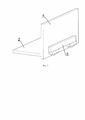
Фиг. 1 – универсальное крепление в разобранном состоянии;FIG. 1 - universal mount in disassembled condition;
Фиг. 2 – выступ планки универсального крепления;FIG. 2 - ledge strips universal mount;
Фиг. 3 – прямоугольный выступ с прямоугольным отверстием универсального крепления;FIG. 3 - a rectangular protrusion with a rectangular hole universal mount;
Фиг. 4 – универсальное крепление в собранном состоянии;FIG. 4 - universal mount in assembled condition;
Фиг. 5 – универсальное крепление с планкой с несколькими выступами в собранном состоянии.FIG. 5 - universal mount with a bracket with several protrusions in the assembled state.
Универсальное крепление (фиг. 1) состоит из прямоугольного выступа 1, расположенного на детали 2, прямоугольного паза 3, расположенного на детали 4 и планки 5 с выступом 6. В выступе 1 выполнено прямоугольное отверстие 7.The universal mount (Fig. 1) consists of a
Выступ 6 на планке 5 (фиг. 2) имеет две фаски 8 по краям и Y-образную прорезь 9. The
Ширина А конца выступа 6 больше, чем ширина В его основания. The width A of the end of the
Ширина А конца выступа 6 больше, чем ширина С (фиг. 3) прямоугольного отверстия 7 в прямоугольном выступе 1 соединяемой детали 2.The width A of the end of the
Пример использования крепления изображен на фиг. 4. Соединение деталей 2 и 4 происходит следующим образом. Выступ 1 плотно вставляется в паз 3 и закрепляется планкой 5, выступ 6 которой вставляется в отверстие 7 на выступе 1 соединяемой детали 2. Фиксация происходит за счет упругих сил возникающих в выступе 6. Наличие прорези 9 позволяет выступу сжиматься и обеспечивает прохождение конца выступа 6 и его надежную фиксацию в отверстии 7.An example of the use of the fastener is shown in FIG. 4. The connection of
На фиг. 5 изображен вариант универсального крепления с планкой 5, на которой выполнено несколько выступов 6.In FIG. 5 shows a variant of universal fastening with a
Наличие фасок 8 облегчает процесс сборки крепления, обеспечивая легкий заход выступа 6 в отверстие 7. The presence of
Y-образная форма прорези позволяет повысить контактную прочность крепления, исключив концентраторы напряжений в выступе 6, и обеспечивает надежность крепления.The Y-shape of the slot allows you to increase the contact strength of the mount, eliminating stress concentrators in the
Таким образом, предложенное в полезной модели техническое решение обеспечивает прочное и надежное соединение деталей, а также обеспечивает технологичность сборки и разборки и тем самым способствуют достижению технического результата.Thus, the technical solution proposed in the utility model provides a strong and reliable connection of parts, as well as ensures the manufacturability of assembly and disassembly, and thereby contribute to the achievement of the technical result.
Claims (4)
Priority Applications (1)
| Application Number | Priority Date | Filing Date | Title |
|---|---|---|---|
| RU2019132682U RU197410U1 (en) | 2019-10-15 | 2019-10-15 | UNIVERSAL FASTENING |
Applications Claiming Priority (1)
| Application Number | Priority Date | Filing Date | Title |
|---|---|---|---|
| RU2019132682U RU197410U1 (en) | 2019-10-15 | 2019-10-15 | UNIVERSAL FASTENING |
Publications (1)
| Publication Number | Publication Date |
|---|---|
| RU197410U1 true RU197410U1 (en) | 2020-04-23 |
Family
ID=70415809
Family Applications (1)
| Application Number | Title | Priority Date | Filing Date |
|---|---|---|---|
| RU2019132682U RU197410U1 (en) | 2019-10-15 | 2019-10-15 | UNIVERSAL FASTENING |
Country Status (1)
| Country | Link |
|---|---|
| RU (1) | RU197410U1 (en) |
Cited By (1)
| Publication number | Priority date | Publication date | Assignee | Title |
|---|---|---|---|---|
| US20210254655A1 (en) * | 2020-02-14 | 2021-08-19 | Mario Brosche | Clip for releasably connecting components |
Citations (3)
| Publication number | Priority date | Publication date | Assignee | Title |
|---|---|---|---|---|
| RU2686379C1 (en) * | 2018-05-21 | 2019-04-25 | Алексей Алексеевич Астахов | Construction toy |
| RU192423U1 (en) * | 2019-06-14 | 2019-09-16 | Общество с ограниченной ответственностью "МЭС" | UNIVERSAL FASTENING |
| RU192906U1 (en) * | 2019-06-14 | 2019-10-07 | Общество с ограниченной ответственностью "МЭС" | A part with a mounting protrusion for connecting to the groove of the counterpart |
-
2019
- 2019-10-15 RU RU2019132682U patent/RU197410U1/en active
Patent Citations (3)
| Publication number | Priority date | Publication date | Assignee | Title |
|---|---|---|---|---|
| RU2686379C1 (en) * | 2018-05-21 | 2019-04-25 | Алексей Алексеевич Астахов | Construction toy |
| RU192423U1 (en) * | 2019-06-14 | 2019-09-16 | Общество с ограниченной ответственностью "МЭС" | UNIVERSAL FASTENING |
| RU192906U1 (en) * | 2019-06-14 | 2019-10-07 | Общество с ограниченной ответственностью "МЭС" | A part with a mounting protrusion for connecting to the groove of the counterpart |
Cited By (1)
| Publication number | Priority date | Publication date | Assignee | Title |
|---|---|---|---|---|
| US20210254655A1 (en) * | 2020-02-14 | 2021-08-19 | Mario Brosche | Clip for releasably connecting components |
Similar Documents
| Publication | Publication Date | Title |
|---|---|---|
| RU192423U1 (en) | UNIVERSAL FASTENING | |
| RU191532U1 (en) | UNIVERSAL FASTENING | |
| RU192906U1 (en) | A part with a mounting protrusion for connecting to the groove of the counterpart | |
| RU186389U1 (en) | CLIPS | |
| RU188737U1 (en) | CLIPS | |
| RU189527U1 (en) | UNIVERSAL FASTENING | |
| RU196647U1 (en) | UNIVERSAL FASTENING | |
| RU196541U1 (en) | UNIVERSAL FASTENING | |
| RU200005U1 (en) | UNIVERSAL MOUNTING | |
| RU197410U1 (en) | UNIVERSAL FASTENING | |
| RU201101U1 (en) | CLIPS | |
| RU194205U1 (en) | UNIVERSAL FASTENING | |
| RU200430U1 (en) | UNIVERSAL MOUNTING | |
| RU202437U1 (en) | Detachable connection for constructor | |
| RU196539U1 (en) | CLIPS | |
| RU194240U1 (en) | FASTENING FLAT PARTS | |
| RU200373U1 (en) | CYLINDRICAL ELEMENT CLAMP | |
| RU192739U1 (en) | CLIPS | |
| RU202436U1 (en) | UNIVERSAL MOUNTING | |
| RU196994U1 (en) | MOBILE FASTENING | |
| RU198870U1 (en) | UNIVERSAL MOUNTING | |
| RU192255U1 (en) | CLIPS | |
| RU205120U1 (en) | UNIVERSAL MOUNTING | |
| RU205619U1 (en) | UNIVERSAL MOUNTING | |
| RU201188U1 (en) | FLAT DETAIL |