EP2877718B1 - Soupape de regulation d'huile pour système de distribution - Google Patents
Soupape de regulation d'huile pour système de distribution Download PDFInfo
- Publication number
- EP2877718B1 EP2877718B1 EP14714146.9A EP14714146A EP2877718B1 EP 2877718 B1 EP2877718 B1 EP 2877718B1 EP 14714146 A EP14714146 A EP 14714146A EP 2877718 B1 EP2877718 B1 EP 2877718B1
- Authority
- EP
- European Patent Office
- Prior art keywords
- control
- port
- adapter
- exhaust
- primary
- Prior art date
- Legal status (The legal status is an assumption and is not a legal conclusion. Google has not performed a legal analysis and makes no representation as to the accuracy of the status listed.)
- Not-in-force
Links
Images
Classifications
-
- F—MECHANICAL ENGINEERING; LIGHTING; HEATING; WEAPONS; BLASTING
- F16—ENGINEERING ELEMENTS AND UNITS; GENERAL MEASURES FOR PRODUCING AND MAINTAINING EFFECTIVE FUNCTIONING OF MACHINES OR INSTALLATIONS; THERMAL INSULATION IN GENERAL
- F16N—LUBRICATING
- F16N25/00—Distributing equipment with or without proportioning devices
- F16N25/02—Distributing equipment with or without proportioning devices with reciprocating distributing slide valve
-
- F—MECHANICAL ENGINEERING; LIGHTING; HEATING; WEAPONS; BLASTING
- F01—MACHINES OR ENGINES IN GENERAL; ENGINE PLANTS IN GENERAL; STEAM ENGINES
- F01L—CYCLICALLY OPERATING VALVES FOR MACHINES OR ENGINES
- F01L13/00—Modifications of valve-gear to facilitate reversing, braking, starting, changing compression ratio, or other specific operations
- F01L13/0005—Deactivating valves
-
- F—MECHANICAL ENGINEERING; LIGHTING; HEATING; WEAPONS; BLASTING
- F16—ENGINEERING ELEMENTS AND UNITS; GENERAL MEASURES FOR PRODUCING AND MAINTAINING EFFECTIVE FUNCTIONING OF MACHINES OR INSTALLATIONS; THERMAL INSULATION IN GENERAL
- F16K—VALVES; TAPS; COCKS; ACTUATING-FLOATS; DEVICES FOR VENTING OR AERATING
- F16K11/00—Multiple-way valves, e.g. mixing valves; Pipe fittings incorporating such valves
- F16K11/02—Multiple-way valves, e.g. mixing valves; Pipe fittings incorporating such valves with all movable sealing faces moving as one unit
- F16K11/06—Multiple-way valves, e.g. mixing valves; Pipe fittings incorporating such valves with all movable sealing faces moving as one unit comprising only sliding valves, i.e. sliding closure elements
- F16K11/065—Multiple-way valves, e.g. mixing valves; Pipe fittings incorporating such valves with all movable sealing faces moving as one unit comprising only sliding valves, i.e. sliding closure elements with linearly sliding closure members
- F16K11/07—Multiple-way valves, e.g. mixing valves; Pipe fittings incorporating such valves with all movable sealing faces moving as one unit comprising only sliding valves, i.e. sliding closure elements with linearly sliding closure members with cylindrical slides
- F16K11/0716—Multiple-way valves, e.g. mixing valves; Pipe fittings incorporating such valves with all movable sealing faces moving as one unit comprising only sliding valves, i.e. sliding closure elements with linearly sliding closure members with cylindrical slides with fluid passages through the valve member
-
- F—MECHANICAL ENGINEERING; LIGHTING; HEATING; WEAPONS; BLASTING
- F16—ENGINEERING ELEMENTS AND UNITS; GENERAL MEASURES FOR PRODUCING AND MAINTAINING EFFECTIVE FUNCTIONING OF MACHINES OR INSTALLATIONS; THERMAL INSULATION IN GENERAL
- F16K—VALVES; TAPS; COCKS; ACTUATING-FLOATS; DEVICES FOR VENTING OR AERATING
- F16K27/00—Construction of housing; Use of materials therefor
- F16K27/02—Construction of housing; Use of materials therefor of lift valves
- F16K27/029—Electromagnetically actuated valves
-
- F—MECHANICAL ENGINEERING; LIGHTING; HEATING; WEAPONS; BLASTING
- F16—ENGINEERING ELEMENTS AND UNITS; GENERAL MEASURES FOR PRODUCING AND MAINTAINING EFFECTIVE FUNCTIONING OF MACHINES OR INSTALLATIONS; THERMAL INSULATION IN GENERAL
- F16K—VALVES; TAPS; COCKS; ACTUATING-FLOATS; DEVICES FOR VENTING OR AERATING
- F16K31/00—Actuating devices; Operating means; Releasing devices
- F16K31/02—Actuating devices; Operating means; Releasing devices electric; magnetic
- F16K31/06—Actuating devices; Operating means; Releasing devices electric; magnetic using a magnet, e.g. diaphragm valves, cutting off by means of a liquid
- F16K31/0603—Multiple-way valves
- F16K31/061—Sliding valves
- F16K31/0613—Sliding valves with cylindrical slides
-
- F—MECHANICAL ENGINEERING; LIGHTING; HEATING; WEAPONS; BLASTING
- F16—ENGINEERING ELEMENTS AND UNITS; GENERAL MEASURES FOR PRODUCING AND MAINTAINING EFFECTIVE FUNCTIONING OF MACHINES OR INSTALLATIONS; THERMAL INSULATION IN GENERAL
- F16K—VALVES; TAPS; COCKS; ACTUATING-FLOATS; DEVICES FOR VENTING OR AERATING
- F16K31/00—Actuating devices; Operating means; Releasing devices
- F16K31/02—Actuating devices; Operating means; Releasing devices electric; magnetic
- F16K31/06—Actuating devices; Operating means; Releasing devices electric; magnetic using a magnet, e.g. diaphragm valves, cutting off by means of a liquid
- F16K31/0603—Multiple-way valves
- F16K31/0624—Lift valves
- F16K31/0634—Lift valves with fixed seats positioned between movable valve members
-
- F—MECHANICAL ENGINEERING; LIGHTING; HEATING; WEAPONS; BLASTING
- F16—ENGINEERING ELEMENTS AND UNITS; GENERAL MEASURES FOR PRODUCING AND MAINTAINING EFFECTIVE FUNCTIONING OF MACHINES OR INSTALLATIONS; THERMAL INSULATION IN GENERAL
- F16K—VALVES; TAPS; COCKS; ACTUATING-FLOATS; DEVICES FOR VENTING OR AERATING
- F16K31/00—Actuating devices; Operating means; Releasing devices
- F16K31/12—Actuating devices; Operating means; Releasing devices actuated by fluid
- F16K31/122—Actuating devices; Operating means; Releasing devices actuated by fluid the fluid acting on a piston
- F16K31/124—Actuating devices; Operating means; Releasing devices actuated by fluid the fluid acting on a piston servo actuated
- F16K31/1245—Actuating devices; Operating means; Releasing devices actuated by fluid the fluid acting on a piston servo actuated with more than one valve
-
- F—MECHANICAL ENGINEERING; LIGHTING; HEATING; WEAPONS; BLASTING
- F01—MACHINES OR ENGINES IN GENERAL; ENGINE PLANTS IN GENERAL; STEAM ENGINES
- F01L—CYCLICALLY OPERATING VALVES FOR MACHINES OR ENGINES
- F01L1/00—Valve-gear or valve arrangements, e.g. lift-valve gear
- F01L1/34—Valve-gear or valve arrangements, e.g. lift-valve gear characterised by the provision of means for changing the timing of the valves without changing the duration of opening and without affecting the magnitude of the valve lift
- F01L1/344—Valve-gear or valve arrangements, e.g. lift-valve gear characterised by the provision of means for changing the timing of the valves without changing the duration of opening and without affecting the magnitude of the valve lift changing the angular relationship between crankshaft and camshaft, e.g. using helicoidal gear
- F01L1/3442—Valve-gear or valve arrangements, e.g. lift-valve gear characterised by the provision of means for changing the timing of the valves without changing the duration of opening and without affecting the magnitude of the valve lift changing the angular relationship between crankshaft and camshaft, e.g. using helicoidal gear using hydraulic chambers with variable volume to transmit the rotating force
- F01L2001/34423—Details relating to the hydraulic feeding circuit
- F01L2001/34426—Oil control valves
- F01L2001/3443—Solenoid driven oil control valves
-
- F—MECHANICAL ENGINEERING; LIGHTING; HEATING; WEAPONS; BLASTING
- F16—ENGINEERING ELEMENTS AND UNITS; GENERAL MEASURES FOR PRODUCING AND MAINTAINING EFFECTIVE FUNCTIONING OF MACHINES OR INSTALLATIONS; THERMAL INSULATION IN GENERAL
- F16K—VALVES; TAPS; COCKS; ACTUATING-FLOATS; DEVICES FOR VENTING OR AERATING
- F16K11/00—Multiple-way valves, e.g. mixing valves; Pipe fittings incorporating such valves
- F16K11/02—Multiple-way valves, e.g. mixing valves; Pipe fittings incorporating such valves with all movable sealing faces moving as one unit
- F16K11/06—Multiple-way valves, e.g. mixing valves; Pipe fittings incorporating such valves with all movable sealing faces moving as one unit comprising only sliding valves, i.e. sliding closure elements
- F16K11/065—Multiple-way valves, e.g. mixing valves; Pipe fittings incorporating such valves with all movable sealing faces moving as one unit comprising only sliding valves, i.e. sliding closure elements with linearly sliding closure members
- F16K11/07—Multiple-way valves, e.g. mixing valves; Pipe fittings incorporating such valves with all movable sealing faces moving as one unit comprising only sliding valves, i.e. sliding closure elements with linearly sliding closure members with cylindrical slides
-
- F—MECHANICAL ENGINEERING; LIGHTING; HEATING; WEAPONS; BLASTING
- F16—ENGINEERING ELEMENTS AND UNITS; GENERAL MEASURES FOR PRODUCING AND MAINTAINING EFFECTIVE FUNCTIONING OF MACHINES OR INSTALLATIONS; THERMAL INSULATION IN GENERAL
- F16K—VALVES; TAPS; COCKS; ACTUATING-FLOATS; DEVICES FOR VENTING OR AERATING
- F16K31/00—Actuating devices; Operating means; Releasing devices
- F16K31/12—Actuating devices; Operating means; Releasing devices actuated by fluid
- F16K31/122—Actuating devices; Operating means; Releasing devices actuated by fluid the fluid acting on a piston
- F16K31/124—Actuating devices; Operating means; Releasing devices actuated by fluid the fluid acting on a piston servo actuated
-
- Y—GENERAL TAGGING OF NEW TECHNOLOGICAL DEVELOPMENTS; GENERAL TAGGING OF CROSS-SECTIONAL TECHNOLOGIES SPANNING OVER SEVERAL SECTIONS OF THE IPC; TECHNICAL SUBJECTS COVERED BY FORMER USPC CROSS-REFERENCE ART COLLECTIONS [XRACs] AND DIGESTS
- Y10—TECHNICAL SUBJECTS COVERED BY FORMER USPC
- Y10T—TECHNICAL SUBJECTS COVERED BY FORMER US CLASSIFICATION
- Y10T137/00—Fluid handling
- Y10T137/8593—Systems
- Y10T137/86493—Multi-way valve unit
- Y10T137/86574—Supply and exhaust
- Y10T137/86582—Pilot-actuated
- Y10T137/86614—Electric
-
- Y—GENERAL TAGGING OF NEW TECHNOLOGICAL DEVELOPMENTS; GENERAL TAGGING OF CROSS-SECTIONAL TECHNOLOGIES SPANNING OVER SEVERAL SECTIONS OF THE IPC; TECHNICAL SUBJECTS COVERED BY FORMER USPC CROSS-REFERENCE ART COLLECTIONS [XRACs] AND DIGESTS
- Y10—TECHNICAL SUBJECTS COVERED BY FORMER USPC
- Y10T—TECHNICAL SUBJECTS COVERED BY FORMER US CLASSIFICATION
- Y10T137/00—Fluid handling
- Y10T137/8593—Systems
- Y10T137/86493—Multi-way valve unit
- Y10T137/86574—Supply and exhaust
- Y10T137/8667—Reciprocating valve
- Y10T137/86694—Piston valve
- Y10T137/8671—With annular passage [e.g., spool]
Definitions
- the present teachings generally include an oil control valve for a valvetrain of an engine.
- Hydraulic control systems for engines include oil control valves that are used to control oil under pressure for various purposes, such as but not limited to switching latch pins in switching lifters, lash adjusters, and rocker arms for cam switching.
- the oil control valves all operate in the same manner to control oil flow, but because they are located at different locations on the engine, fluid ports of the different oil control valves may have to be positioned at different relative axial locations along a central axis of the oil control valve.
- An oil control valve assembly according to the preamble of claim 1 is disclosed in DE 41 11 064 A1 .
- the oil control valve assembly includes a valve body that extends along a longitudinal axis between an interior end and an exterior end.
- the valve body includes a supply land, a control land, and an exhaust land; and defines a secondary supply port, a secondary supply port, a primary control port, and a primary exhaust port.
- the secondary supply port is disposed at the interior rend of the valve body.
- the secondary supply port is disposed nearer the interior end of the valve body than the primary control port and the primary exhaust port.
- the secondary supply port is disposed radially nearer the longitudinal axis than the primary control port and the primary exhaust port.
- the primary control port is disposed nearer the interior end of the valve body than the primary exhaust port.
- the primary control port is disposed radially nearer the longitudinal axis than the primary exhaust port.
- the supply land is disposed between the secondary supply port and the primary control port.
- the control land is disposed between the primary control port and the primary exhaust port.
- the exhaust land is disposed between the primary exhaust port and the exterior end of the valve body.
- An adapter assembly is coupled to the valve body.
- the adapter assembly includes an adapter body that extends along the longitudinal axis.
- the adapter body defines an adapter supply port, an adapter control port, and an adapter exhaust port.
- a supply tube is attached to the adapter body and supported by the supply land.
- the supply tube includes an interior that defines a supply passage in fluid communication with the primary supply port, the secondary supply port, and the adapter supply port.
- a control tube is attached to the adapter body and supported by the control land.
- the control tube includes an interior that defines a control passage in fluid communication with the primary control port and the adapter supply port.
- An exhaust tube is attached to the adapter body and supported by the exhaust land.
- the exhaust tube includes an interior that defines an exhaust passage in fluid communication with the primary exhaust port and the adapter exhaust port.
- the oil control valve includes a valve body that extends along a longitudinal axis between an interior end and an exterior end.
- a controller is coupled to the exterior end of the valve body.
- the controller includes a solenoid housing that is attached to the exterior end of the valve body.
- the solenoid housing defines an interior region.
- An encapsulated coil assembly is supported by and disposed within the interior region of the solenoid housing.
- a housing seal is disposed within the interior region of the solenoid housing, in sealing engagement with the solenoid housing, the valve body, and the encapsulated coil assembly. The housing seal is operable to seal the interior region of the solenoid housing to prevent fluid communication between the solenoid housing and the valve body.
- the adapter assembly is attached to the valve body to effectively axially relocate the fluid ports of the oil control valve along the longitudinal axis so that the same oil control valve may be used at different locations on the engine.
- the oil control valve includes the housing seal to prevent any contamination that may enter into the solenoid housing from passing into the sealed chambers of the engine, thereby allowing the control valve to be used in different locations of the engine.
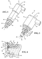
- an oil control valve assembly is generally shown at 20.
- the oil control valve assembly 20 includes an oil control valve 22 and an adapter assembly 24.
- the oil control valve 22 may be used independently of the adapter assembly 24, or may be combined with the adapter assembly 24 to form the oil control valve assembly 20.
- the oil control valve 22, with our without the adapter assembly 24, is used to control a flow of hydraulic fluid, e.g., oil, which is used to actuate various components of an engine.
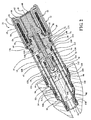
- the oil control valve 22 is shown in Figures 1 and 2 with the adapter assembly 24 attached thereto.
- the oil control valve 22 is shown in Figure 3 without the adapter assembly 24 attached thereto.
- the oil control valve 22 includes a valve body 26 that extends along a longitudinal axis 28, between an interior end 30 and an exterior end 32 of the valve body 26.
- the interior end 30 of the valve body 26 is configured for insertion into a bore 34, which defines fluid passageways in fluid communication with the component to be controlled.
- the valve body 26 includes a supply land 36, a control land 38, and an exhaust land 40, and defines a primary supply port 41, a secondary supply port 42, a primary control port 44, and a primary exhaust port 46.
- the primary supply port 41 is disposed at the interior end 30 of the valve body 26.
- the secondary supply port 42 is disposed nearer the interior end 30 of the valve body 26 than the primary control port 44 and the primary exhaust port 46.
- the secondary supply port 42 is disposed radially nearer the longitudinal axis 28 than the primary control port 44 and the primary exhaust port 46.
- the primary control port 44 is disposed nearer the interior end 30 of the valve body 26 than the primary exhaust port 46.
- the primary control port 44 is disposed radially nearer the longitudinal axis 28 than the primary exhaust port 46.
- the supply land 36 is disposed between the support port and the primary control port 44.
- the control land 38 is disposed between the primary control port 44 and the primary exhaust port 46.
- the exhaust land 40 is disposed between the primary exhaust port 46 and the exterior end 32 of the valve body 26.
- a controller 48 e.g., a solenoid
- the controller 48 shown in Figure 2 and described herein is a solenoid controller 48. However, it should be appreciated that the controller 48 may include some other device capable of controlling the flow of fluid through the valve body 26.
- the controller 48 includes a housing, hereinafter referred to as a solenoid housing 50, which is attached to the exterior end 32 of the valve body 26.
- An encapsulated coil assembly 52 is supported by and disposed within an interior region 54 of the solenoid housing 50.
- the encapsulated coil assembly 52 includes a bobbin 56 and a wire magnet 58.
- An armature 60 is concentrically disposed about the longitudinal axis 28 and responsive to move axially along the longitudinal axis 28.
- An armature cap 62 positions the armature 60 relative to the solenoid housing 50.
- the armature cap 62 includes a flange 64 disposed against the exterior end 32 of the valve body 26, and secured in position relative to the valve body 26 by the encapsulated coil assembly 52.
- An armature cap seal 66 is supported by and disposed between the valve body 26 and the armature cap 62.
- the armature cap seal 66 is operable to seal between the valve body 26 and the armature cap 62.
- a flux collector 68 also referred to as a flux bracket
- radially supports the armature cap 62 and is disposed between the armature cap 62 and the encapsulated coil assembly 52.
- the controller 48 is engaged and/or disengaged to move a push pin 70 axially along the longitudinal axis 28.
- the push pin 70 is disposed within a central bore 72 defined by the valve body 26, which extends along and is concentric about the longitudinal axis 28.
- the push pin 70 is coupled to the armature 60 for movement with the armature 60 along the longitudinal axis 28.
- An exhaust poppet 74 is disposed within the central bore 72 of the valve body 26, radially about an exterior of the push pin 70.
- the exhaust poppet 74 is moveable along the longitudinal axis 28 relative to the push pin 70 and the valve body 26.
- An exhaust spring 76 is disposed within the central bore 72 of the valve body 26, radially about the exhaust poppet 74. The exhaust spring 76 biases the exhaust poppet 74 away from the armature 60 and into a blocking position to seal the primary exhaust port 46.
- the armature 60 and the push pin 70 connected thereto are movable in the central bore 72 of the valve body 26 in response to electrically energizing the encapsulated coil assembly 52.
- the encapsulated coil assembly 52, the armature 60 and flux collector 68 form an electromagnet. Lines of flux are created in an air gap between the encapsulated coil assembly 52 and the armature 60 when the encapsulated coil assembly 52 is energized by an electric source, such as but not limited to a battery (not shown).
- the armature 60 moves along the longitudinal axis 28 in response to the flux.
- the encapsulated coil assembly 52 is energized under the control of an electronic controller 48 (not shown) in response to various engine operating conditions.
- the controller 48 may be engaged, i.e., an electric current applied to the controller 48, to move the push pin 70 along the longitudinal axis 28 to open fluid communication through the primary supply port 41.
- the controller 48 may be engaged, i.e., an electric current applied to the controller 48, to move the push pin 70 along the longitudinal axis 28 to close fluid communication through the primary supply port 41.
- the secondary supply port 42 is always open to fluid pressure to communicate fluid pressure therethrough into the central bore 72 of the valve body 26. This allows make-up oil to flow to the hydraulic system through the primary control port 44 and the primary exhaust port 46, depending on the hydraulic system backpressure.
- a much larger flow of the supply oil is allowed into the central bore 72 and through the oil control valve 22.
- a housing seal 78 is disposed within the interior region 54 of the solenoid housing 50.
- the housing seal 78 is disposed in sealing engagement with the solenoid housing 50, the valve body 26, and the encapsulated coil assembly 52.
- the housing seal 78 is operable to seal the interior region 54 of the solenoid housing 50 to prevent fluid communication between the solenoid housing 50 and the valve body 26, and to prevent contamination that may enter the controller 48 from exiting the solenoid housing 50, at a location identified in Figure 4 by reference numeral 144.
- the encapsulated coil assembly 52 includes an outer surface 80 that is disposed adjacent an interior surface 82 of the solenoid housing 50.
- the encapsulated coil assembly 52 includes an axial end surface 84 that is disposed adjacent the exterior end 32 of the valve body 26.
- the encapsulated coil assembly 52 includes an annular chamfered surface 86.
- the annular chamfered surface 86 interconnects the outer surface 80 of the encapsulated coil assembly 52 and the axial end surface 84 of the encapsulated coil assembly 52, and extends annularly around the longitudinal axis 28.
- the annular chamfered surface 86 forms a chamfered radially outer corner of the encapsulated coil assembly 52 to provide space within the interior region 54 of the solenoid housing 50 for the housing seal 78.
- the annular chamfered surface 86 is sized to accommodate the housing seal 78 along an annular interface 88 between the solenoid housing 50 and the valve body 26.
- the housing seal 78 is disposed adjacent and in sealing engagement with the annular chamfered surface 86, the interior surface 82 of the solenoid housing 50, and the exterior end 32 of the valve body 26.
- the adapter assembly 24 is shown in Figures 1 and 2 coupled to the valve body 26.
- the adapter assembly 24 is operable to reposition a discharge location of each of the secondary supply port 42, the primary control port 44, and the primary exhaust port 46 along the longitudinal axis 28 relative to the valve body 26 to effectively lengthen the valve body 26 along the longitudinal axis 28.
- the adapter assembly 24 includes an adapter body 90 that extends along the longitudinal axis 28.
- the adapter body 90 defines an adapter supply port 92, an adapter control port 94, and an adapter exhaust port 96.
- a supply tube 98 is attached to the adapter body 90, and is supported by the supply land 36.
- the supply tube 98 includes a supply interior 100 that defines a supply passage 102 in fluid communication with the secondary supply port 42 and the adapter supply port 92.
- a control tube 104 is attached to the adapter body 90 and supported by the control land 38.
- the control tube 104 includes a control interior 106 that defines a control passage 108 in fluid communication with the primary control port 44 and the adapter control port 94.
- An exhaust tube 110 is attached to the adapter body 90 and supported by the exhaust land 40.
- the exhaust tube 110 includes an exhaust interior 112 that defines an exhaust passage 114 in fluid communication with the primary exhaust port 46 and the adapter exhaust port 96.
- the supply tube 98, the control tube 104 and the exhaust tube 110 may be attached to the adapter body 90 in any suitable manner, including but not limited to injection molding the adapter body 90 over each of the supply tube 98, the control tube 104 and the exhaust tube 110.
- the supply interior 100 of the supply tube 98 defines a supply diameter 116
- the control interior 106 of the control tube 104 defines a control diameter 118
- the exhaust interior 112 of the exhaust tube 110 defines an exhaust diameter 120.
- the exhaust diameter 120 is larger than both of the control diameter 118 and the supply diameter 116.
- the control diameter 118 is larger than the supply diameter 116.
- the supply tube 98, the control tube 104, and the exhaust tube 110 each include a diametric center line that is coaxially disposed with each other along the longitudinal axis 28 of the valve body 26.
- the supply tube 98 is disposed within the control interior 106 of the control tube 104 and cooperates with the control tube 104 to define the control passage 108.
- the control passage 108 is defined between an exterior surface 122 of the supply tube 98 and an interior surface 124 of the control tube 104.
- the control tube 104 is disposed within the exhaust interior 112 of the exhaust tube 110 and cooperates with the exhaust tube 110 to define the exhaust passage 114.
- the exhaust passage 114 is defined between an exterior surface 126 of the control tube 104 and an interior surface 128 of the exhaust tube 110.
- a first primary seal 130 is supported by the supply land 36 of the valve body 26.
- the first primary seal 130 is operable to seal between the supply tube 98 and the valve body 26 to prevent fluid communication between the secondary supply port 42 and the primary control port 44.
- a second primary seal 132 is supported by the control land 38 of the valve body 26. The second primary seal 132 is operable to seal between the control tube 104 and the valve body 26 to prevent fluid communication between the primary control port 44 and the primary exhaust port 46.
- a third primary seal 134 is supported by the exhaust land 40 of the valve body 26. The third primary seal 134 is operable to seal between the exhaust tube 110 and the valve body 26 to prevent fluid communication between the primary exhaust port 46 and a distal end 136 of the exhaust tube 110.
- a first adapter seal 138 is supported by the adapter body 90 and axially disposed along the longitudinal axis 28 between the adapter supply port 92 and the adapter control port 94.
- the first adapter seal 138 is operable to seal against a wall of the bore 34 to prevent fluid communication between the adapter supply port 92 and the adapter control port 94.
- a second adapter seal 140 is supported by the adapter body 90 and axially disposed along the longitudinal axis 28 between the adapter control port 94 and the adapter exhaust port 96.
- the second adapter seal 140 is operable to seal against the wall of the bore 34 to prevent fluid communication between the adapter control port 94 and the adapter exhaust port 96.
- a third adapter seal 142 is supported by the adapter body 90 and axially disposed along the longitudinal axis 28 between the adapter exhaust port 96 and the distal end 136 of the exhaust tube 110.
- the third adapter seal 142 is operable to seal against the wall of the bore 34 to prevent fluid communication between the adapter exhaust port 96 and the distal end 136 of the exhaust tube 110.
- the valve body 26 defines an annular channel 146.
- the annular channel 146 extends around an outer circumference of the valve body, and extends radially inward into the valve body 26, toward the longitudinal axis 28.
- the exhaust tube 110 includes a radially compressed portion 148 disposed at the distal end 136 if the exhaust tube 110.
- the radially compressed portion 148 defines a diameter that is smaller than the exhaust diameter 120, and extends radially into the annular channel 146 in a snap fit engagement with the valve body 26 to secure the adapter assembly 24 to the oil control valve 22.
Claims (10)
- Ensemble de soupape de régulation d'huile (20) pour un véhicule, l'ensemble de soupape de régulation d'huile (20) comprenant :un corps de soupape (26) s'étendant le long d'un axe longitudinal (28) entre une extrémité intérieure (30) et une extrémité extérieure (32), comprenant une zone d'alimentation (36), une zone de commande (38) et une zone d'échappement (40) et définissant un orifice d'alimentation principal (41), un orifice d'alimentation secondaire (42), un orifice de commande principal (44) et un orifice d'échappement principal (46) ;dans lequel l'orifice d'alimentation principal (41) est disposé au niveau de l'extrémité intérieure (30) du corps de soupape (26) ;dans lequel l'orifice d'alimentation secondaire (42) est disposé plus près de l'extrémité intérieure (30) du corps de soupape (26) que l'orifice de commande principal (44) et l'orifice d'échappement principal (46), et l'orifice d'alimentation secondaire (42) est disposé radialement plus près de l'axe longitudinal (28) que l'orifice de commande principal (44) et l'orifice d'échappement principal (46) ;dans lequel l'orifice de commande principal (44) est disposé plus près de l'extrémité intérieure (30) du corps de soupape (26) que l'orifice d'échappement principal (46), et l'orifice de commande principal (44) est disposé radialement plus près de l'axe longitudinal (28) que l'orifice d'échappement principal (46) ;dans lequel la zone d'alimentation (36) est disposée entre l'orifice d'alimentation secondaire (42) et l'orifice de commande principal (44), la zone de commande (38) est disposée entre l'orifice de commande principal (44) et l'orifice d'échappement principal (46), et la zone d'échappement (40) est disposée entre l'orifice d'échappement principal (46) et l'extrémité extérieure (32) du corps de soupape (26) ; etun ensemble d'adaptateur (24) couplé au corps de soupape (26), l'ensemble d'adaptateur (24) comprenant :un corps d'adaptateur (90) s'étendant le long de l'axe longitudinal (28) et définissant un orifice d'alimentation d'adaptateur (92), un orifice de commande d'adaptateur (94) et un orifice d'échappement d'adaptateur (96) ;caractérisé par :l'ensemble de soupape de régulation d'huile (20) comprenant en outre :un tube d'alimentation (98) fixé au corps d'adaptateur (90) et supporté par la zone d'alimentation (36), avec le tube d'alimentation (98) qui comprend un intérieur d'alimentation (100) qui définit un passage d'alimentation (102) en communication de fluide avec l'orifice d'alimentation principal (41), l'orifice d'alimentation secondaire (42) et l'orifice d'alimentation d'adaptateur (92) ;un tube de commande (104) fixé au corps d'adaptateur (90) et supporté par la zone de commande (38), avec le tube de commande (104) qui comprend un intérieur de commande (106) qui définit un passage de commande (108) en communication de fluide avec l'orifice de commande principal (44) et l'orifice de commande d'adaptateur (94) ; etun tube d'échappement (110) fixé sur le corps d'adaptateur (90) et supporté par la zone d'échappement (40), avec le tube d'échappement (110) qui comprend un intérieur d'échappement (112) qui définit un passage d'échappement (114) en communication de fluide avec l'orifice d'alimentation principal (46) et l'orifice d'échappement d'adaptateur (96).
- Ensemble de soupape de régulation d'huile (20) selon la revendication 1, dans lequel l'intérieur d'alimentation (100) du tube d'alimentation (98) définit un diamètre d'alimentation (116), l'intérieur de commande (106) du tube de commande (104) définit un diamètre de commande (118) et l'intérieur d'échappement (112) du tube d'échappement (110) définit un diamètre d'échappement (120), avec le diamètre d'échappement (120) supérieur à la fois au diamètre de commande (118) et au diamètre d'alimentation (116), et avec le diamètre de commande (118) supérieur au diamètre d'alimentation (116).
- Ensemble de soupape de régulation d'huile (20) selon la revendication 2, dans lequel le tube d'alimentation (98), le tube de commande (104) et le tube d'échappement (110) comprennent une ligne centrale diamétrale qui est disposée de manière coaxiale par rapport à ces derniers le long de l'axe longitudinal (28) du corps de soupape (26).
- Ensemble de soupape de régulation d'huile (20) selon la revendication 3, dans lequel le tube d'alimentation (98) est disposé dans l'intérieur de commande (106) du tube de commande (104) et coopère avec le tube de commande (104) pour définir le passage de commande (108) entre une surface extérieure (122) du tube d'alimentation (98) et une surface intérieure (124) du tube de commande (104) .
- Ensemble de soupape de régulation d'huile (20) selon la revendication 3, dans lequel le tube de commande (104) est disposé dans l'intérieur d'échappement (112) du tube d'échappement (110) et coopère avec le tube d'échappement (110) pour définir le passage d'échappement (114) entre une surface extérieure (126) du tube de commande (104) et une surface intérieure (128) du tube d'échappement (110).
- Ensemble de soupape de régulation d'huile (20) selon la revendication 1, dans lequel l'ensemble d'adaptateur (24) comprend en outre :un premier joint d'étanchéité d'adaptateur (138) supporté par le corps d'adaptateur (90) et axialement disposé le long de l'axe longitudinal (28) entre l'orifice d'alimentation d'adaptateur (92) et l'orifice de commande d'adaptateur (94), dans lequel le premier joint d'étanchéité d'adaptateur (138) peut fonctionner pour se sceller contre une paroi d'alésage (34) pour empêcher la communication de fluide entre l'orifice d'alimentation d'adaptateur (92) et l'orifice de commande d'adaptateur (94) ;un deuxième joint d'étanchéité d'adaptateur (140) supporté par le corps d'adaptateur (90) et axialement disposé le long de l'axe longitudinal (28) entre l'orifice de commande d'adaptateur (94) et l'orifice d'échappement d'adaptateur (96), dans lequel le second joint d'étanchéité d'adaptateur (140) peut fonctionner afin de réaliser l'étanchéité contre la paroi d'alésage (34) pour empêcher la communication de fluide entre l'orifice de commande d'adaptateur (94) et l'orifice d'échappement d'adaptateur (96) ;un troisième joint d'étanchéité d'adaptateur (142) supporté par le corps d'adaptateur (90) et axialement disposé le long de l'axe longitudinal (28) entre l'orifice d'échappement d'adaptateur (96) et une extrémité distale (136) du tube d'échappement (110), dans lequel le troisième joint d'étanchéité d'adaptateur (142) peut fonctionner afin de réaliser l'étanchéité contre la paroi d'alésage (34) pour empêcher la communication de fluide entre l'orifice d'échappement d'adaptateur (96) et l'extrémité distale du tube d'échappement (110),un premier joint d'étanchéité principal (130) supporté par la zone d'alimentation (36) du corps de soupape (26) et pouvant fonctionner pour effectuer une étanchéité entre le tube d'alimentation (98) et le corps de soupape (26) pour empêcher la communication de fluide entre l'orifice d'alimentation secondaire (42) et l'orifice de commande principal (44) ;un deuxième joint d'étanchéité principal (132) supporté par la zone de commande (38) du corps de soupape (26) et pouvant fonctionner pour réaliser un scellement entre le tube de commande (104) et le corps de soupape (26) pour empêcher la communication de fluide entre l'orifice de commande principal (44) et l'orifice d'échappement principal (46) ; etun troisième joint d'étanchéité principal (134) supporté par la zone d'échappement (40) du corps de soupape (26) et pouvant fonctionner pour réaliser une étanchéité entre le tube d'échappement (110) et le corps de soupape (26) pour empêcher la communication de fluide entre l'orifice d'échappement principal (46) et l'extrémité distale (136) du tube d'échappement (110).
- Ensemble de soupape de régulation d'huile (20) selon la revendication 1, comprenant en outre un boîtier de solénoïde (50) fixé sur l'extrémité extérieure (32) du corps de soupape (26) et un ensemble de bobine encapsulé (52) supporté par et disposé à l'intérieur d'une région intérieure (54) du boîtier de solénoïde (50).
- Ensemble de soupape de régulation d'huile (20) selon la revendication 7, comprenant en outre un joint d'étanchéité de boîtier (78) disposé à l'intérieur de la région intérieure (54) du boîtier de solénoïde (50) et disposé en mise en prise d'étanchéité avec le boîtier de solénoïde (50), le corps de soupape (26) et l'ensemble de bobine encapsulé (52).
- Ensemble de soupape de régulation d'huile (20) selon la revendication 8, dans lequel l'ensemble de bobine encapsulé (52) comprend une surface externe (80) disposée de manière adjacente à une surface intérieure (82) du boîtier de solénoïde (50) et une surface d'extrémité axiale (84) disposée de manière adjacente à l'extrémité extérieure (32) du corps de soupape (26), et dans lequel l'ensemble de bobine encapsulé (52) comprend une surface chanfreinée annulaire (86) interconnectant la surface externe (80) et la surface d'extrémité axiale (84) de l'ensemble de bobine encapsulé (52), avec le joint d'étanchéité de boîtier (78) disposé de manière adjacente et en mise en prise d'étanchéité avec la surface chanfreinée annulaire (86), la surface intérieure (82) du boîtier de solénoïde (50) et l'extrémité extérieure (32) du corps de soupape (26).
- Ensemble de soupape de régulation d'huile (20) selon la revendication 1, dans lequel le corps de soupape (26) définit un canal annulaire (146) s'étendant radialement vers l'intérieur à partir d'une surface externe du corps de soupape (26) et dans lequel le tube d'échappement (110) comprend une extrémité radialement compressée (148) s'étendant radialement vers l'intérieur dans le canal annulaire (146) pour fixer l'ensemble d'adaptateur (24) sur la soupape de régulation d'huile.
Priority Applications (1)
| Application Number | Priority Date | Filing Date | Title |
|---|---|---|---|
| EP16193120.9A EP3150810A3 (fr) | 2013-03-14 | 2014-03-14 | Soupape de commande d'huile avec un solenoid |
Applications Claiming Priority (2)
| Application Number | Priority Date | Filing Date | Title |
|---|---|---|---|
| US201361781114P | 2013-03-14 | 2013-03-14 | |
| PCT/US2014/027513 WO2014152596A1 (fr) | 2013-03-14 | 2014-03-14 | By-pass de radiateur d'huile pour dispositif de commande des soupapes moteur |
Related Child Applications (2)
| Application Number | Title | Priority Date | Filing Date |
|---|---|---|---|
| EP16193120.9A Division-Into EP3150810A3 (fr) | 2013-03-14 | 2014-03-14 | Soupape de commande d'huile avec un solenoid |
| EP16193120.9A Division EP3150810A3 (fr) | 2013-03-14 | 2014-03-14 | Soupape de commande d'huile avec un solenoid |
Publications (2)
| Publication Number | Publication Date |
|---|---|
| EP2877718A1 EP2877718A1 (fr) | 2015-06-03 |
| EP2877718B1 true EP2877718B1 (fr) | 2016-11-16 |
Family
ID=50391553
Family Applications (2)
| Application Number | Title | Priority Date | Filing Date |
|---|---|---|---|
| EP14714146.9A Not-in-force EP2877718B1 (fr) | 2013-03-14 | 2014-03-14 | Soupape de regulation d'huile pour système de distribution |
| EP16193120.9A Withdrawn EP3150810A3 (fr) | 2013-03-14 | 2014-03-14 | Soupape de commande d'huile avec un solenoid |
Family Applications After (1)
| Application Number | Title | Priority Date | Filing Date |
|---|---|---|---|
| EP16193120.9A Withdrawn EP3150810A3 (fr) | 2013-03-14 | 2014-03-14 | Soupape de commande d'huile avec un solenoid |
Country Status (5)
| Country | Link |
|---|---|
| US (2) | US9587786B2 (fr) |
| EP (2) | EP2877718B1 (fr) |
| KR (1) | KR20150129645A (fr) |
| CN (2) | CN203868404U (fr) |
| WO (1) | WO2014152596A1 (fr) |
Families Citing this family (2)
| Publication number | Priority date | Publication date | Assignee | Title |
|---|---|---|---|---|
| CN109311388B (zh) | 2016-04-15 | 2022-05-31 | 伊顿智能动力有限公司 | 用于燃料蒸气环境的蒸气不可渗透电磁阀 |
| JP1616176S (fr) * | 2018-01-05 | 2018-10-22 |
Family Cites Families (36)
| Publication number | Priority date | Publication date | Assignee | Title |
|---|---|---|---|---|
| US4276960A (en) * | 1979-05-17 | 1981-07-07 | Ingersoll-Rand Company | Oil distributing means |
| US4741364A (en) * | 1987-06-12 | 1988-05-03 | Deere & Company | Pilot-operated valve with load pressure feedback |
| US4895192A (en) * | 1987-12-24 | 1990-01-23 | Sundstrand Corporation | Process and apparatus for filling a constant speed drive |
| US5042832A (en) * | 1988-01-29 | 1991-08-27 | Nissan Motor Company, Limited | Proportioning valve assembly and actively controlled suspension system utilizing the same |
| US5024459A (en) * | 1988-12-28 | 1991-06-18 | Toyota Jidosha Kabushiki Kaisha | Pressure control system for suspension |
| DE4111064A1 (de) * | 1991-04-05 | 1992-10-08 | Rexroth Mannesmann Gmbh | Wegeventil mit zwei beabstandeten ventilkoerpern |
| US5836335A (en) * | 1991-08-19 | 1998-11-17 | Fluid Power Industries, Inc. | Proportional pressure control valve |
| US5855228A (en) * | 1995-09-05 | 1999-01-05 | Perach; Asi | Control valve assembly |
| JP3633166B2 (ja) * | 1996-12-28 | 2005-03-30 | アイシン・エィ・ダブリュ株式会社 | リニアソレノイド |
| DE19983712T1 (de) * | 1999-09-14 | 2002-03-14 | Mitsubishi Electric Corp | Ölsteuerventil |
| US6701959B1 (en) * | 2002-08-06 | 2004-03-09 | Husco International, Inc. | High flow rate balanced poppet valve |
| EP1420321A3 (fr) * | 2002-11-15 | 2005-04-20 | HydraForce, Inc. | Vanne de réduction de pression proportionnelle agissant sur deux pressions |
| US6904937B2 (en) * | 2002-12-11 | 2005-06-14 | Delphi Technologies, Inc. | Switchable fluid control valve system |
| US6938873B2 (en) * | 2003-12-01 | 2005-09-06 | Delphi Technologies, Inc. | Compound valve assembly for controlling high and low oil flow and pressure |
| DE10359363A1 (de) * | 2003-12-18 | 2005-07-14 | Ina-Schaeffler Kg | Elektromagnetisches Hydraulikventil, inbesondere 3/2-Wegeschaltventil zur Steuerung eines variablen Ventiltriebes einer Brennkraftmaschine |
| DE10359364B4 (de) * | 2003-12-18 | 2012-10-11 | Schaeffler Technologies Gmbh & Co. Kg | Elektromagnetisches Hydraulikventil, insbesondere 3/2-Wegeschaltventil zur Steuerung eines varialblen Ventiltriebes einer Brennkraftmaschine |
| US7779853B2 (en) * | 2004-02-24 | 2010-08-24 | Parker-Hannifin Corporation | Proportional pressure control valve |
| US7331564B2 (en) * | 2005-04-22 | 2008-02-19 | Delphi Technologies, Inc. | Normally open high flow hydraulic pressure control actuator |
| US8167000B2 (en) * | 2007-04-05 | 2012-05-01 | Mac Valves, Inc. | Balanced solenoid valve |
| US8151824B2 (en) * | 2007-04-05 | 2012-04-10 | Mac Valves, Inc. | Balanced solenoid valve |
| DE102007036925A1 (de) * | 2007-08-04 | 2009-02-05 | Schaeffler Kg | Elektromagnetische Stelleinheit |
| US7921880B2 (en) * | 2007-08-20 | 2011-04-12 | Hydraforce, Inc. | Three-way poppet valve with intermediate pilot port |
| US7862471B2 (en) * | 2007-09-11 | 2011-01-04 | Gm Global Technology Operations, Inc. | Valve control system |
| US9157544B2 (en) * | 2008-05-29 | 2015-10-13 | Aisin Aw Co., Ltd. | Solenoid valve |
| US20100019186A1 (en) * | 2008-07-25 | 2010-01-28 | Eaton Corporation | Engine valve assembly with valve can mountable to an engine cover |
| US8042789B2 (en) * | 2008-10-06 | 2011-10-25 | Eaton Corporation | Valve for distributing fluids |
| US8684037B2 (en) * | 2009-08-05 | 2014-04-01 | Eaton Corportion | Proportional poppet valve with integral check valve |
| US8443839B2 (en) * | 2009-10-20 | 2013-05-21 | Eaton Corporation | Fluid-biased hydraulic control valve with armature piston |
| US8960233B2 (en) * | 2009-11-27 | 2015-02-24 | Eagle Industry Co., Ltd. | Solenoid valve |
| US8757208B2 (en) * | 2009-12-10 | 2014-06-24 | Hydraforce, Inc. | Proportional motion control valve |
| KR100948508B1 (ko) * | 2009-12-15 | 2010-03-23 | 주식회사 유니크 | 가변 밸브 리프트 시스템용 오일 제어 밸브 |
| US8607823B2 (en) * | 2010-07-13 | 2013-12-17 | Delphi Technologies, Inc. | Pressure control valve |
| DE102010055025A1 (de) * | 2010-12-17 | 2012-06-21 | Pierburg Gmbh | Elektromagnetventil |
| DE102010055026A1 (de) * | 2010-12-17 | 2012-06-21 | Pierburg Gmbh | Elektromagnetventil |
| KR101198809B1 (ko) * | 2011-05-16 | 2012-11-07 | 주식회사 유니크 | 오일 제어 밸브 및 이를 포함하는 가변 밸브 리프트 시스템 |
| US8459218B2 (en) * | 2011-05-19 | 2013-06-11 | Eaton Corporation | Adjustable-stroke solenoid valve |
-
2014
- 2014-03-14 CN CN201420115714.2U patent/CN203868404U/zh not_active Expired - Fee Related
- 2014-03-14 CN CN201410094082.0A patent/CN104295768A/zh active Pending
- 2014-03-14 WO PCT/US2014/027513 patent/WO2014152596A1/fr active Application Filing
- 2014-03-14 EP EP14714146.9A patent/EP2877718B1/fr not_active Not-in-force
- 2014-03-14 EP EP16193120.9A patent/EP3150810A3/fr not_active Withdrawn
- 2014-03-14 KR KR1020157013861A patent/KR20150129645A/ko not_active Application Discontinuation
- 2014-12-15 US US14/570,363 patent/US9587786B2/en not_active Expired - Fee Related
-
2017
- 2017-01-19 US US15/410,009 patent/US20170130897A1/en not_active Abandoned
Also Published As
| Publication number | Publication date |
|---|---|
| EP2877718A1 (fr) | 2015-06-03 |
| US20150096636A1 (en) | 2015-04-09 |
| CN203868404U (zh) | 2014-10-08 |
| US9587786B2 (en) | 2017-03-07 |
| US20170130897A1 (en) | 2017-05-11 |
| WO2014152596A1 (fr) | 2014-09-25 |
| EP3150810A3 (fr) | 2017-07-05 |
| EP3150810A2 (fr) | 2017-04-05 |
| CN104295768A (zh) | 2015-01-21 |
| KR20150129645A (ko) | 2015-11-20 |
Similar Documents
| Publication | Publication Date | Title |
|---|---|---|
| JP5984798B2 (ja) | マニホールド用加圧oリング磁極片 | |
| KR101301803B1 (ko) | 전자기식 액추에이팅 유닛 | |
| KR20170044753A (ko) | 내연기관의 컴프레서를 위한 오버런 에어 재순환 밸브 | |
| US8844900B2 (en) | Activation element of an electromagnetic actuating unit of a hydraulic valve | |
| EP2798248B1 (fr) | Ensemble électrovanne avec commande de pression pilote | |
| US20150192059A1 (en) | Thermostatic valve for controlling the temperature of the coolant in an internal combustion engine | |
| EP2877718B1 (fr) | Soupape de regulation d'huile pour système de distribution | |
| US9523438B2 (en) | Solenoid valve assembly with pilot pressure control | |
| US20150219222A1 (en) | Valve Assembly for an Injection Valve and Injection Valve | |
| US7367357B2 (en) | Solenoid ball valve with bypass orifice | |
| EP2021667B1 (fr) | Valve hydraulique a commande electrique | |
| US8746279B2 (en) | Pressure control valve | |
| US20100101517A1 (en) | Valve drive of an internal combustion engine | |
| KR101659801B1 (ko) | 통합된 솔레노이드 밸브를 갖춘 흡기장치 | |
| US10054245B2 (en) | Valve assembly with vent port between supply port and control port | |
| CN111306349A (zh) | 油控制阀 | |
| EP4283170A1 (fr) | Électrovanne | |
| WO2018089614A1 (fr) | Ensemble électrovanne avec commande de pression pilote | |
| US20180372237A1 (en) | Normally closed fast-acting solenoid valve | |
| US20160319751A1 (en) | Digital linear actuator large port side-gated control valve for electronic throttle control | |
| US10927719B2 (en) | Variable cam timing phaser having two central control valves | |
| JP2023046322A (ja) | 二段バルブアセンブリ |
Legal Events
| Date | Code | Title | Description |
|---|---|---|---|
| PUAI | Public reference made under article 153(3) epc to a published international application that has entered the european phase |
Free format text: ORIGINAL CODE: 0009012 |
|
| 17P | Request for examination filed |
Effective date: 20141215 |
|
| AK | Designated contracting states |
Kind code of ref document: A1 Designated state(s): AL AT BE BG CH CY CZ DE DK EE ES FI FR GB GR HR HU IE IS IT LI LT LU LV MC MK MT NL NO PL PT RO RS SE SI SK SM TR |
|
| AX | Request for extension of the european patent |
Extension state: BA ME |
|
| 17Q | First examination report despatched |
Effective date: 20160309 |
|
| GRAP | Despatch of communication of intention to grant a patent |
Free format text: ORIGINAL CODE: EPIDOSNIGR1 |
|
| DAX | Request for extension of the european patent (deleted) | ||
| INTG | Intention to grant announced |
Effective date: 20160610 |
|
| GRAS | Grant fee paid |
Free format text: ORIGINAL CODE: EPIDOSNIGR3 |
|
| GRAA | (expected) grant |
Free format text: ORIGINAL CODE: 0009210 |
|
| AK | Designated contracting states |
Kind code of ref document: B1 Designated state(s): AL AT BE BG CH CY CZ DE DK EE ES FI FR GB GR HR HU IE IS IT LI LT LU LV MC MK MT NL NO PL PT RO RS SE SI SK SM TR |
|
| REG | Reference to a national code |
Ref country code: GB Ref legal event code: FG4D |
|
| REG | Reference to a national code |
Ref country code: CH Ref legal event code: EP |
|
| REG | Reference to a national code |
Ref country code: IE Ref legal event code: FG4D |
|
| REG | Reference to a national code |
Ref country code: AT Ref legal event code: REF Ref document number: 846164 Country of ref document: AT Kind code of ref document: T Effective date: 20161215 |
|
| REG | Reference to a national code |
Ref country code: DE Ref legal event code: R096 Ref document number: 602014004924 Country of ref document: DE |
|
| PG25 | Lapsed in a contracting state [announced via postgrant information from national office to epo] |
Ref country code: LV Free format text: LAPSE BECAUSE OF FAILURE TO SUBMIT A TRANSLATION OF THE DESCRIPTION OR TO PAY THE FEE WITHIN THE PRESCRIBED TIME-LIMIT Effective date: 20161116 |
|
| REG | Reference to a national code |
Ref country code: NL Ref legal event code: MP Effective date: 20161116 Ref country code: FR Ref legal event code: PLFP Year of fee payment: 4 |
|
| REG | Reference to a national code |
Ref country code: LT Ref legal event code: MG4D |
|
| REG | Reference to a national code |
Ref country code: AT Ref legal event code: MK05 Ref document number: 846164 Country of ref document: AT Kind code of ref document: T Effective date: 20161116 |
|
| PG25 | Lapsed in a contracting state [announced via postgrant information from national office to epo] |
Ref country code: GR Free format text: LAPSE BECAUSE OF FAILURE TO SUBMIT A TRANSLATION OF THE DESCRIPTION OR TO PAY THE FEE WITHIN THE PRESCRIBED TIME-LIMIT Effective date: 20170217 Ref country code: NL Free format text: LAPSE BECAUSE OF FAILURE TO SUBMIT A TRANSLATION OF THE DESCRIPTION OR TO PAY THE FEE WITHIN THE PRESCRIBED TIME-LIMIT Effective date: 20161116 Ref country code: LT Free format text: LAPSE BECAUSE OF FAILURE TO SUBMIT A TRANSLATION OF THE DESCRIPTION OR TO PAY THE FEE WITHIN THE PRESCRIBED TIME-LIMIT Effective date: 20161116 Ref country code: NO Free format text: LAPSE BECAUSE OF FAILURE TO SUBMIT A TRANSLATION OF THE DESCRIPTION OR TO PAY THE FEE WITHIN THE PRESCRIBED TIME-LIMIT Effective date: 20170216 Ref country code: SE Free format text: LAPSE BECAUSE OF FAILURE TO SUBMIT A TRANSLATION OF THE DESCRIPTION OR TO PAY THE FEE WITHIN THE PRESCRIBED TIME-LIMIT Effective date: 20161116 |
|
| PG25 | Lapsed in a contracting state [announced via postgrant information from national office to epo] |
Ref country code: ES Free format text: LAPSE BECAUSE OF FAILURE TO SUBMIT A TRANSLATION OF THE DESCRIPTION OR TO PAY THE FEE WITHIN THE PRESCRIBED TIME-LIMIT Effective date: 20161116 Ref country code: PT Free format text: LAPSE BECAUSE OF FAILURE TO SUBMIT A TRANSLATION OF THE DESCRIPTION OR TO PAY THE FEE WITHIN THE PRESCRIBED TIME-LIMIT Effective date: 20170316 Ref country code: RS Free format text: LAPSE BECAUSE OF FAILURE TO SUBMIT A TRANSLATION OF THE DESCRIPTION OR TO PAY THE FEE WITHIN THE PRESCRIBED TIME-LIMIT Effective date: 20161116 Ref country code: AT Free format text: LAPSE BECAUSE OF FAILURE TO SUBMIT A TRANSLATION OF THE DESCRIPTION OR TO PAY THE FEE WITHIN THE PRESCRIBED TIME-LIMIT Effective date: 20161116 Ref country code: PL Free format text: LAPSE BECAUSE OF FAILURE TO SUBMIT A TRANSLATION OF THE DESCRIPTION OR TO PAY THE FEE WITHIN THE PRESCRIBED TIME-LIMIT Effective date: 20161116 Ref country code: FI Free format text: LAPSE BECAUSE OF FAILURE TO SUBMIT A TRANSLATION OF THE DESCRIPTION OR TO PAY THE FEE WITHIN THE PRESCRIBED TIME-LIMIT Effective date: 20161116 Ref country code: HR Free format text: LAPSE BECAUSE OF FAILURE TO SUBMIT A TRANSLATION OF THE DESCRIPTION OR TO PAY THE FEE WITHIN THE PRESCRIBED TIME-LIMIT Effective date: 20161116 |
|
| PG25 | Lapsed in a contracting state [announced via postgrant information from national office to epo] |
Ref country code: RO Free format text: LAPSE BECAUSE OF FAILURE TO SUBMIT A TRANSLATION OF THE DESCRIPTION OR TO PAY THE FEE WITHIN THE PRESCRIBED TIME-LIMIT Effective date: 20161116 Ref country code: SK Free format text: LAPSE BECAUSE OF FAILURE TO SUBMIT A TRANSLATION OF THE DESCRIPTION OR TO PAY THE FEE WITHIN THE PRESCRIBED TIME-LIMIT Effective date: 20161116 Ref country code: EE Free format text: LAPSE BECAUSE OF FAILURE TO SUBMIT A TRANSLATION OF THE DESCRIPTION OR TO PAY THE FEE WITHIN THE PRESCRIBED TIME-LIMIT Effective date: 20161116 Ref country code: DK Free format text: LAPSE BECAUSE OF FAILURE TO SUBMIT A TRANSLATION OF THE DESCRIPTION OR TO PAY THE FEE WITHIN THE PRESCRIBED TIME-LIMIT Effective date: 20161116 Ref country code: CZ Free format text: LAPSE BECAUSE OF FAILURE TO SUBMIT A TRANSLATION OF THE DESCRIPTION OR TO PAY THE FEE WITHIN THE PRESCRIBED TIME-LIMIT Effective date: 20161116 |
|
| REG | Reference to a national code |
Ref country code: DE Ref legal event code: R097 Ref document number: 602014004924 Country of ref document: DE |
|
| PG25 | Lapsed in a contracting state [announced via postgrant information from national office to epo] |
Ref country code: SM Free format text: LAPSE BECAUSE OF FAILURE TO SUBMIT A TRANSLATION OF THE DESCRIPTION OR TO PAY THE FEE WITHIN THE PRESCRIBED TIME-LIMIT Effective date: 20161116 Ref country code: IT Free format text: LAPSE BECAUSE OF FAILURE TO SUBMIT A TRANSLATION OF THE DESCRIPTION OR TO PAY THE FEE WITHIN THE PRESCRIBED TIME-LIMIT Effective date: 20161116 Ref country code: BE Free format text: LAPSE BECAUSE OF FAILURE TO SUBMIT A TRANSLATION OF THE DESCRIPTION OR TO PAY THE FEE WITHIN THE PRESCRIBED TIME-LIMIT Effective date: 20161116 Ref country code: BG Free format text: LAPSE BECAUSE OF FAILURE TO SUBMIT A TRANSLATION OF THE DESCRIPTION OR TO PAY THE FEE WITHIN THE PRESCRIBED TIME-LIMIT Effective date: 20170216 |
|
| PLBE | No opposition filed within time limit |
Free format text: ORIGINAL CODE: 0009261 |
|
| STAA | Information on the status of an ep patent application or granted ep patent |
Free format text: STATUS: NO OPPOSITION FILED WITHIN TIME LIMIT |
|
| 26N | No opposition filed |
Effective date: 20170817 |
|
| REG | Reference to a national code |
Ref country code: CH Ref legal event code: PL |
|
| PG25 | Lapsed in a contracting state [announced via postgrant information from national office to epo] |
Ref country code: MC Free format text: LAPSE BECAUSE OF FAILURE TO SUBMIT A TRANSLATION OF THE DESCRIPTION OR TO PAY THE FEE WITHIN THE PRESCRIBED TIME-LIMIT Effective date: 20161116 Ref country code: SI Free format text: LAPSE BECAUSE OF FAILURE TO SUBMIT A TRANSLATION OF THE DESCRIPTION OR TO PAY THE FEE WITHIN THE PRESCRIBED TIME-LIMIT Effective date: 20161116 |
|
| REG | Reference to a national code |
Ref country code: IE Ref legal event code: MM4A |
|
| PG25 | Lapsed in a contracting state [announced via postgrant information from national office to epo] |
Ref country code: LU Free format text: LAPSE BECAUSE OF NON-PAYMENT OF DUE FEES Effective date: 20170314 |
|
| REG | Reference to a national code |
Ref country code: FR Ref legal event code: PLFP Year of fee payment: 5 |
|
| PG25 | Lapsed in a contracting state [announced via postgrant information from national office to epo] |
Ref country code: LI Free format text: LAPSE BECAUSE OF NON-PAYMENT OF DUE FEES Effective date: 20170331 Ref country code: IE Free format text: LAPSE BECAUSE OF NON-PAYMENT OF DUE FEES Effective date: 20170314 Ref country code: CH Free format text: LAPSE BECAUSE OF NON-PAYMENT OF DUE FEES Effective date: 20170331 |
|
| PGFP | Annual fee paid to national office [announced via postgrant information from national office to epo] |
Ref country code: GB Payment date: 20180226 Year of fee payment: 5 Ref country code: DE Payment date: 20180219 Year of fee payment: 5 |
|
| PGFP | Annual fee paid to national office [announced via postgrant information from national office to epo] |
Ref country code: FR Payment date: 20180220 Year of fee payment: 5 |
|
| PG25 | Lapsed in a contracting state [announced via postgrant information from national office to epo] |
Ref country code: MT Free format text: LAPSE BECAUSE OF NON-PAYMENT OF DUE FEES Effective date: 20170314 |
|
| REG | Reference to a national code |
Ref country code: GB Ref legal event code: 732E Free format text: REGISTERED BETWEEN 20181115 AND 20181130 |
|
| REG | Reference to a national code |
Ref country code: DE Ref legal event code: R082 Ref document number: 602014004924 Country of ref document: DE Ref country code: DE Ref legal event code: R081 Ref document number: 602014004924 Country of ref document: DE Owner name: EATON INTELLIGENT POWER LIMITED, IE Free format text: FORMER OWNER: EATON CORPORATION, CLEVELAND, OHIO, US |
|
| PG25 | Lapsed in a contracting state [announced via postgrant information from national office to epo] |
Ref country code: HU Free format text: LAPSE BECAUSE OF FAILURE TO SUBMIT A TRANSLATION OF THE DESCRIPTION OR TO PAY THE FEE WITHIN THE PRESCRIBED TIME-LIMIT; INVALID AB INITIO Effective date: 20140314 |
|
| REG | Reference to a national code |
Ref country code: DE Ref legal event code: R119 Ref document number: 602014004924 Country of ref document: DE |
|
| PG25 | Lapsed in a contracting state [announced via postgrant information from national office to epo] |
Ref country code: CY Free format text: LAPSE BECAUSE OF FAILURE TO SUBMIT A TRANSLATION OF THE DESCRIPTION OR TO PAY THE FEE WITHIN THE PRESCRIBED TIME-LIMIT Effective date: 20161116 |
|
| GBPC | Gb: european patent ceased through non-payment of renewal fee |
Effective date: 20190314 |
|
| PG25 | Lapsed in a contracting state [announced via postgrant information from national office to epo] |
Ref country code: MK Free format text: LAPSE BECAUSE OF FAILURE TO SUBMIT A TRANSLATION OF THE DESCRIPTION OR TO PAY THE FEE WITHIN THE PRESCRIBED TIME-LIMIT Effective date: 20161116 |
|
| PG25 | Lapsed in a contracting state [announced via postgrant information from national office to epo] |
Ref country code: DE Free format text: LAPSE BECAUSE OF NON-PAYMENT OF DUE FEES Effective date: 20191001 Ref country code: GB Free format text: LAPSE BECAUSE OF NON-PAYMENT OF DUE FEES Effective date: 20190314 |
|
| PG25 | Lapsed in a contracting state [announced via postgrant information from national office to epo] |
Ref country code: FR Free format text: LAPSE BECAUSE OF NON-PAYMENT OF DUE FEES Effective date: 20190331 |
|
| PG25 | Lapsed in a contracting state [announced via postgrant information from national office to epo] |
Ref country code: TR Free format text: LAPSE BECAUSE OF FAILURE TO SUBMIT A TRANSLATION OF THE DESCRIPTION OR TO PAY THE FEE WITHIN THE PRESCRIBED TIME-LIMIT Effective date: 20161116 |
|
| PG25 | Lapsed in a contracting state [announced via postgrant information from national office to epo] |
Ref country code: AL Free format text: LAPSE BECAUSE OF FAILURE TO SUBMIT A TRANSLATION OF THE DESCRIPTION OR TO PAY THE FEE WITHIN THE PRESCRIBED TIME-LIMIT Effective date: 20161116 Ref country code: IS Free format text: LAPSE BECAUSE OF FAILURE TO SUBMIT A TRANSLATION OF THE DESCRIPTION OR TO PAY THE FEE WITHIN THE PRESCRIBED TIME-LIMIT Effective date: 20170316 |