EP2877718B1 - Engine valvetrain oil control valve - Google Patents
Engine valvetrain oil control valve Download PDFInfo
- Publication number
- EP2877718B1 EP2877718B1 EP14714146.9A EP14714146A EP2877718B1 EP 2877718 B1 EP2877718 B1 EP 2877718B1 EP 14714146 A EP14714146 A EP 14714146A EP 2877718 B1 EP2877718 B1 EP 2877718B1
- Authority
- EP
- European Patent Office
- Prior art keywords
- control
- port
- adapter
- exhaust
- primary
- Prior art date
- Legal status (The legal status is an assumption and is not a legal conclusion. Google has not performed a legal analysis and makes no representation as to the accuracy of the status listed.)
- Not-in-force
Links
Images
Classifications
-
- F—MECHANICAL ENGINEERING; LIGHTING; HEATING; WEAPONS; BLASTING
- F16—ENGINEERING ELEMENTS AND UNITS; GENERAL MEASURES FOR PRODUCING AND MAINTAINING EFFECTIVE FUNCTIONING OF MACHINES OR INSTALLATIONS; THERMAL INSULATION IN GENERAL
- F16N—LUBRICATING
- F16N25/00—Distributing equipment with or without proportioning devices
- F16N25/02—Distributing equipment with or without proportioning devices with reciprocating distributing slide valve
-
- F—MECHANICAL ENGINEERING; LIGHTING; HEATING; WEAPONS; BLASTING
- F01—MACHINES OR ENGINES IN GENERAL; ENGINE PLANTS IN GENERAL; STEAM ENGINES
- F01L—CYCLICALLY OPERATING VALVES FOR MACHINES OR ENGINES
- F01L13/00—Modifications of valve-gear to facilitate reversing, braking, starting, changing compression ratio, or other specific operations
- F01L13/0005—Deactivating valves
-
- F—MECHANICAL ENGINEERING; LIGHTING; HEATING; WEAPONS; BLASTING
- F16—ENGINEERING ELEMENTS AND UNITS; GENERAL MEASURES FOR PRODUCING AND MAINTAINING EFFECTIVE FUNCTIONING OF MACHINES OR INSTALLATIONS; THERMAL INSULATION IN GENERAL
- F16K—VALVES; TAPS; COCKS; ACTUATING-FLOATS; DEVICES FOR VENTING OR AERATING
- F16K11/00—Multiple-way valves, e.g. mixing valves; Pipe fittings incorporating such valves
- F16K11/02—Multiple-way valves, e.g. mixing valves; Pipe fittings incorporating such valves with all movable sealing faces moving as one unit
- F16K11/06—Multiple-way valves, e.g. mixing valves; Pipe fittings incorporating such valves with all movable sealing faces moving as one unit comprising only sliding valves, i.e. sliding closure elements
- F16K11/065—Multiple-way valves, e.g. mixing valves; Pipe fittings incorporating such valves with all movable sealing faces moving as one unit comprising only sliding valves, i.e. sliding closure elements with linearly sliding closure members
- F16K11/07—Multiple-way valves, e.g. mixing valves; Pipe fittings incorporating such valves with all movable sealing faces moving as one unit comprising only sliding valves, i.e. sliding closure elements with linearly sliding closure members with cylindrical slides
- F16K11/0716—Multiple-way valves, e.g. mixing valves; Pipe fittings incorporating such valves with all movable sealing faces moving as one unit comprising only sliding valves, i.e. sliding closure elements with linearly sliding closure members with cylindrical slides with fluid passages through the valve member
-
- F—MECHANICAL ENGINEERING; LIGHTING; HEATING; WEAPONS; BLASTING
- F16—ENGINEERING ELEMENTS AND UNITS; GENERAL MEASURES FOR PRODUCING AND MAINTAINING EFFECTIVE FUNCTIONING OF MACHINES OR INSTALLATIONS; THERMAL INSULATION IN GENERAL
- F16K—VALVES; TAPS; COCKS; ACTUATING-FLOATS; DEVICES FOR VENTING OR AERATING
- F16K27/00—Construction of housing; Use of materials therefor
- F16K27/02—Construction of housing; Use of materials therefor of lift valves
- F16K27/029—Electromagnetically actuated valves
-
- F—MECHANICAL ENGINEERING; LIGHTING; HEATING; WEAPONS; BLASTING
- F16—ENGINEERING ELEMENTS AND UNITS; GENERAL MEASURES FOR PRODUCING AND MAINTAINING EFFECTIVE FUNCTIONING OF MACHINES OR INSTALLATIONS; THERMAL INSULATION IN GENERAL
- F16K—VALVES; TAPS; COCKS; ACTUATING-FLOATS; DEVICES FOR VENTING OR AERATING
- F16K31/00—Actuating devices; Operating means; Releasing devices
- F16K31/02—Actuating devices; Operating means; Releasing devices electric; magnetic
- F16K31/06—Actuating devices; Operating means; Releasing devices electric; magnetic using a magnet, e.g. diaphragm valves, cutting off by means of a liquid
- F16K31/0603—Multiple-way valves
- F16K31/061—Sliding valves
- F16K31/0613—Sliding valves with cylindrical slides
-
- F—MECHANICAL ENGINEERING; LIGHTING; HEATING; WEAPONS; BLASTING
- F16—ENGINEERING ELEMENTS AND UNITS; GENERAL MEASURES FOR PRODUCING AND MAINTAINING EFFECTIVE FUNCTIONING OF MACHINES OR INSTALLATIONS; THERMAL INSULATION IN GENERAL
- F16K—VALVES; TAPS; COCKS; ACTUATING-FLOATS; DEVICES FOR VENTING OR AERATING
- F16K31/00—Actuating devices; Operating means; Releasing devices
- F16K31/02—Actuating devices; Operating means; Releasing devices electric; magnetic
- F16K31/06—Actuating devices; Operating means; Releasing devices electric; magnetic using a magnet, e.g. diaphragm valves, cutting off by means of a liquid
- F16K31/0603—Multiple-way valves
- F16K31/0624—Lift valves
- F16K31/0634—Lift valves with fixed seats positioned between movable valve members
-
- F—MECHANICAL ENGINEERING; LIGHTING; HEATING; WEAPONS; BLASTING
- F16—ENGINEERING ELEMENTS AND UNITS; GENERAL MEASURES FOR PRODUCING AND MAINTAINING EFFECTIVE FUNCTIONING OF MACHINES OR INSTALLATIONS; THERMAL INSULATION IN GENERAL
- F16K—VALVES; TAPS; COCKS; ACTUATING-FLOATS; DEVICES FOR VENTING OR AERATING
- F16K31/00—Actuating devices; Operating means; Releasing devices
- F16K31/12—Actuating devices; Operating means; Releasing devices actuated by fluid
- F16K31/122—Actuating devices; Operating means; Releasing devices actuated by fluid the fluid acting on a piston
- F16K31/124—Actuating devices; Operating means; Releasing devices actuated by fluid the fluid acting on a piston servo actuated
- F16K31/1245—Actuating devices; Operating means; Releasing devices actuated by fluid the fluid acting on a piston servo actuated with more than one valve
-
- F—MECHANICAL ENGINEERING; LIGHTING; HEATING; WEAPONS; BLASTING
- F01—MACHINES OR ENGINES IN GENERAL; ENGINE PLANTS IN GENERAL; STEAM ENGINES
- F01L—CYCLICALLY OPERATING VALVES FOR MACHINES OR ENGINES
- F01L1/00—Valve-gear or valve arrangements, e.g. lift-valve gear
- F01L1/34—Valve-gear or valve arrangements, e.g. lift-valve gear characterised by the provision of means for changing the timing of the valves without changing the duration of opening and without affecting the magnitude of the valve lift
- F01L1/344—Valve-gear or valve arrangements, e.g. lift-valve gear characterised by the provision of means for changing the timing of the valves without changing the duration of opening and without affecting the magnitude of the valve lift changing the angular relationship between crankshaft and camshaft, e.g. using helicoidal gear
- F01L1/3442—Valve-gear or valve arrangements, e.g. lift-valve gear characterised by the provision of means for changing the timing of the valves without changing the duration of opening and without affecting the magnitude of the valve lift changing the angular relationship between crankshaft and camshaft, e.g. using helicoidal gear using hydraulic chambers with variable volume to transmit the rotating force
- F01L2001/34423—Details relating to the hydraulic feeding circuit
- F01L2001/34426—Oil control valves
- F01L2001/3443—Solenoid driven oil control valves
-
- F—MECHANICAL ENGINEERING; LIGHTING; HEATING; WEAPONS; BLASTING
- F16—ENGINEERING ELEMENTS AND UNITS; GENERAL MEASURES FOR PRODUCING AND MAINTAINING EFFECTIVE FUNCTIONING OF MACHINES OR INSTALLATIONS; THERMAL INSULATION IN GENERAL
- F16K—VALVES; TAPS; COCKS; ACTUATING-FLOATS; DEVICES FOR VENTING OR AERATING
- F16K11/00—Multiple-way valves, e.g. mixing valves; Pipe fittings incorporating such valves
- F16K11/02—Multiple-way valves, e.g. mixing valves; Pipe fittings incorporating such valves with all movable sealing faces moving as one unit
- F16K11/06—Multiple-way valves, e.g. mixing valves; Pipe fittings incorporating such valves with all movable sealing faces moving as one unit comprising only sliding valves, i.e. sliding closure elements
- F16K11/065—Multiple-way valves, e.g. mixing valves; Pipe fittings incorporating such valves with all movable sealing faces moving as one unit comprising only sliding valves, i.e. sliding closure elements with linearly sliding closure members
- F16K11/07—Multiple-way valves, e.g. mixing valves; Pipe fittings incorporating such valves with all movable sealing faces moving as one unit comprising only sliding valves, i.e. sliding closure elements with linearly sliding closure members with cylindrical slides
-
- F—MECHANICAL ENGINEERING; LIGHTING; HEATING; WEAPONS; BLASTING
- F16—ENGINEERING ELEMENTS AND UNITS; GENERAL MEASURES FOR PRODUCING AND MAINTAINING EFFECTIVE FUNCTIONING OF MACHINES OR INSTALLATIONS; THERMAL INSULATION IN GENERAL
- F16K—VALVES; TAPS; COCKS; ACTUATING-FLOATS; DEVICES FOR VENTING OR AERATING
- F16K31/00—Actuating devices; Operating means; Releasing devices
- F16K31/12—Actuating devices; Operating means; Releasing devices actuated by fluid
- F16K31/122—Actuating devices; Operating means; Releasing devices actuated by fluid the fluid acting on a piston
- F16K31/124—Actuating devices; Operating means; Releasing devices actuated by fluid the fluid acting on a piston servo actuated
-
- Y—GENERAL TAGGING OF NEW TECHNOLOGICAL DEVELOPMENTS; GENERAL TAGGING OF CROSS-SECTIONAL TECHNOLOGIES SPANNING OVER SEVERAL SECTIONS OF THE IPC; TECHNICAL SUBJECTS COVERED BY FORMER USPC CROSS-REFERENCE ART COLLECTIONS [XRACs] AND DIGESTS
- Y10—TECHNICAL SUBJECTS COVERED BY FORMER USPC
- Y10T—TECHNICAL SUBJECTS COVERED BY FORMER US CLASSIFICATION
- Y10T137/00—Fluid handling
- Y10T137/8593—Systems
- Y10T137/86493—Multi-way valve unit
- Y10T137/86574—Supply and exhaust
- Y10T137/86582—Pilot-actuated
- Y10T137/86614—Electric
-
- Y—GENERAL TAGGING OF NEW TECHNOLOGICAL DEVELOPMENTS; GENERAL TAGGING OF CROSS-SECTIONAL TECHNOLOGIES SPANNING OVER SEVERAL SECTIONS OF THE IPC; TECHNICAL SUBJECTS COVERED BY FORMER USPC CROSS-REFERENCE ART COLLECTIONS [XRACs] AND DIGESTS
- Y10—TECHNICAL SUBJECTS COVERED BY FORMER USPC
- Y10T—TECHNICAL SUBJECTS COVERED BY FORMER US CLASSIFICATION
- Y10T137/00—Fluid handling
- Y10T137/8593—Systems
- Y10T137/86493—Multi-way valve unit
- Y10T137/86574—Supply and exhaust
- Y10T137/8667—Reciprocating valve
- Y10T137/86694—Piston valve
- Y10T137/8671—With annular passage [e.g., spool]
Landscapes
- Engineering & Computer Science (AREA)
- General Engineering & Computer Science (AREA)
- Mechanical Engineering (AREA)
- Physics & Mathematics (AREA)
- Electromagnetism (AREA)
- Magnetically Actuated Valves (AREA)
Description
- The present teachings generally include an oil control valve for a valvetrain of an engine.
- Hydraulic control systems for engines include oil control valves that are used to control oil under pressure for various purposes, such as but not limited to switching latch pins in switching lifters, lash adjusters, and rocker arms for cam switching. The oil control valves all operate in the same manner to control oil flow, but because they are located at different locations on the engine, fluid ports of the different oil control valves may have to be positioned at different relative axial locations along a central axis of the oil control valve. An oil control valve assembly according to the preamble of claim 1 is disclosed in
DE 41 11 064 A1 - An oil control valve assembly for a vehicle is provided. The oil control valve assembly includes a valve body that extends along a longitudinal axis between an interior end and an exterior end. The valve body includes a supply land, a control land, and an exhaust land; and defines a secondary supply port, a secondary supply port, a primary control port, and a primary exhaust port. The secondary supply port is disposed at the interior rend of the valve body. The secondary supply port is disposed nearer the interior end of the valve body than the primary control port and the primary exhaust port. The secondary supply port is disposed radially nearer the longitudinal axis than the primary control port and the primary exhaust port. The primary control port is disposed nearer the interior end of the valve body than the primary exhaust port. The primary control port is disposed radially nearer the longitudinal axis than the primary exhaust port. The supply land is disposed between the secondary supply port and the primary control port. The control land is disposed between the primary control port and the primary exhaust port. The exhaust land is disposed between the primary exhaust port and the exterior end of the valve body. An adapter assembly is coupled to the valve body. The adapter assembly includes an adapter body that extends along the longitudinal axis. The adapter body defines an adapter supply port, an adapter control port, and an adapter exhaust port. A supply tube is attached to the adapter body and supported by the supply land. The supply tube includes an interior that defines a supply passage in fluid communication with the primary supply port, the secondary supply port, and the adapter supply port. A control tube is attached to the adapter body and supported by the control land. The control tube includes an interior that defines a control passage in fluid communication with the primary control port and the adapter supply port. An exhaust tube is attached to the adapter body and supported by the exhaust land. The exhaust tube includes an interior that defines an exhaust passage in fluid communication with the primary exhaust port and the adapter exhaust port.
- An oil control valve is also provided. The oil control valve includes a valve body that extends along a longitudinal axis between an interior end and an exterior end. A controller is coupled to the exterior end of the valve body. The controller includes a solenoid housing that is attached to the exterior end of the valve body. The solenoid housing defines an interior region. An encapsulated coil assembly is supported by and disposed within the interior region of the solenoid housing. A housing seal is disposed within the interior region of the solenoid housing, in sealing engagement with the solenoid housing, the valve body, and the encapsulated coil assembly. The housing seal is operable to seal the interior region of the solenoid housing to prevent fluid communication between the solenoid housing and the valve body.
- Accordingly, the adapter assembly is attached to the valve body to effectively axially relocate the fluid ports of the oil control valve along the longitudinal axis so that the same oil control valve may be used at different locations on the engine. The oil control valve includes the housing seal to prevent any contamination that may enter into the solenoid housing from passing into the sealed chambers of the engine, thereby allowing the control valve to be used in different locations of the engine.
- The above features and advantages and other features and advantages of the present invention are readily apparent from the following detailed description of the best modes for carrying out the invention when taken in connection with the accompanying drawings.
-
-
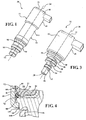
Figure 1 is a schematic perspective view of an oil control valve assembly. -
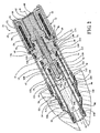
Figure 2 is a schematic cross sectional view of the oil control valve assembly. -
Figure 3 is a schematic perspective view of an oil control valve of the oil control valve assembly. -
Figure 4 is an enlarged schematic fragmentary perspective view of the oil control valve assembly showing a housing seal. - Those having ordinary skill in the art will recognize that terms such as "above," "below," "upward," "downward," "top," "bottom," etc., are used descriptively for the figures, and do not represent limitations on the scope of the invention, as defined by the appended claims. Furthermore, the invention may be described herein in terms of functional and/or logical block components and/or various processing steps. It should be realized that such block components may be realized by any number of hardware, software, and/or firmware components configured to perform the specified functions.
- Referring to the Figures, wherein like numerals indicate like parts throughout the several views, an oil control valve assembly is generally shown at 20. The oil
control valve assembly 20 includes anoil control valve 22 and anadapter assembly 24. Theoil control valve 22 may be used independently of theadapter assembly 24, or may be combined with theadapter assembly 24 to form the oilcontrol valve assembly 20. Theoil control valve 22, with our without theadapter assembly 24, is used to control a flow of hydraulic fluid, e.g., oil, which is used to actuate various components of an engine. Theoil control valve 22 is shown inFigures 1 and2 with theadapter assembly 24 attached thereto. Theoil control valve 22 is shown inFigure 3 without theadapter assembly 24 attached thereto. - Referring to
Figure 2 , theoil control valve 22 includes avalve body 26 that extends along alongitudinal axis 28, between aninterior end 30 and anexterior end 32 of thevalve body 26. Theinterior end 30 of thevalve body 26 is configured for insertion into abore 34, which defines fluid passageways in fluid communication with the component to be controlled. Thevalve body 26 includes asupply land 36, acontrol land 38, and anexhaust land 40, and defines aprimary supply port 41, asecondary supply port 42, aprimary control port 44, and aprimary exhaust port 46. Theprimary supply port 41 is disposed at theinterior end 30 of thevalve body 26. Thesecondary supply port 42 is disposed nearer theinterior end 30 of thevalve body 26 than theprimary control port 44 and theprimary exhaust port 46. Thesecondary supply port 42 is disposed radially nearer thelongitudinal axis 28 than theprimary control port 44 and theprimary exhaust port 46. Theprimary control port 44 is disposed nearer theinterior end 30 of thevalve body 26 than theprimary exhaust port 46. Theprimary control port 44 is disposed radially nearer thelongitudinal axis 28 than theprimary exhaust port 46. Thesupply land 36 is disposed between the support port and theprimary control port 44. Thecontrol land 38 is disposed between theprimary control port 44 and theprimary exhaust port 46. Theexhaust land 40 is disposed between theprimary exhaust port 46 and theexterior end 32 of thevalve body 26. - A
controller 48, e.g., a solenoid, is coupled to theexterior end 32 of thevalve body 26. Thecontroller 48 shown inFigure 2 and described herein is asolenoid controller 48. However, it should be appreciated that thecontroller 48 may include some other device capable of controlling the flow of fluid through thevalve body 26. Thecontroller 48 includes a housing, hereinafter referred to as asolenoid housing 50, which is attached to theexterior end 32 of thevalve body 26. An encapsulatedcoil assembly 52 is supported by and disposed within aninterior region 54 of thesolenoid housing 50. The encapsulatedcoil assembly 52 includes a bobbin 56 and awire magnet 58. Anarmature 60 is concentrically disposed about thelongitudinal axis 28 and responsive to move axially along thelongitudinal axis 28. Anarmature cap 62 positions thearmature 60 relative to thesolenoid housing 50. Thearmature cap 62 includes aflange 64 disposed against theexterior end 32 of thevalve body 26, and secured in position relative to thevalve body 26 by the encapsulatedcoil assembly 52. Anarmature cap seal 66 is supported by and disposed between thevalve body 26 and thearmature cap 62. Thearmature cap seal 66 is operable to seal between thevalve body 26 and thearmature cap 62. A flux collector 68 (also referred to as a flux bracket) radially supports thearmature cap 62, and is disposed between thearmature cap 62 and the encapsulatedcoil assembly 52. - The
controller 48 is engaged and/or disengaged to move apush pin 70 axially along thelongitudinal axis 28. Thepush pin 70 is disposed within acentral bore 72 defined by thevalve body 26, which extends along and is concentric about thelongitudinal axis 28. Thepush pin 70 is coupled to thearmature 60 for movement with thearmature 60 along thelongitudinal axis 28. Anexhaust poppet 74 is disposed within thecentral bore 72 of thevalve body 26, radially about an exterior of thepush pin 70. Theexhaust poppet 74 is moveable along thelongitudinal axis 28 relative to thepush pin 70 and thevalve body 26. Anexhaust spring 76 is disposed within thecentral bore 72 of thevalve body 26, radially about theexhaust poppet 74. Theexhaust spring 76 biases theexhaust poppet 74 away from thearmature 60 and into a blocking position to seal theprimary exhaust port 46. - The
armature 60 and thepush pin 70 connected thereto are movable in thecentral bore 72 of thevalve body 26 in response to electrically energizing the encapsulatedcoil assembly 52. The encapsulatedcoil assembly 52, thearmature 60 and flux collector 68 form an electromagnet. Lines of flux are created in an air gap between the encapsulatedcoil assembly 52 and thearmature 60 when the encapsulatedcoil assembly 52 is energized by an electric source, such as but not limited to a battery (not shown). Thearmature 60 moves along thelongitudinal axis 28 in response to the flux. The encapsulatedcoil assembly 52 is energized under the control of an electronic controller 48 (not shown) in response to various engine operating conditions. Thecontroller 48 may be engaged, i.e., an electric current applied to thecontroller 48, to move thepush pin 70 along thelongitudinal axis 28 to open fluid communication through theprimary supply port 41. Alternatively, thecontroller 48 may be engaged, i.e., an electric current applied to thecontroller 48, to move thepush pin 70 along thelongitudinal axis 28 to close fluid communication through theprimary supply port 41. Thesecondary supply port 42 is always open to fluid pressure to communicate fluid pressure therethrough into thecentral bore 72 of thevalve body 26. This allows make-up oil to flow to the hydraulic system through theprimary control port 44 and theprimary exhaust port 46, depending on the hydraulic system backpressure. When thepush pin 70 is moved to open fluid communication through theprimary supply port 41, a much larger flow of the supply oil is allowed into thecentral bore 72 and through theoil control valve 22. - Referring to
Figure 4 , ahousing seal 78 is disposed within theinterior region 54 of thesolenoid housing 50. Thehousing seal 78 is disposed in sealing engagement with thesolenoid housing 50, thevalve body 26, and the encapsulatedcoil assembly 52. Thehousing seal 78 is operable to seal theinterior region 54 of thesolenoid housing 50 to prevent fluid communication between thesolenoid housing 50 and thevalve body 26, and to prevent contamination that may enter thecontroller 48 from exiting thesolenoid housing 50, at a location identified inFigure 4 byreference numeral 144. - The encapsulated
coil assembly 52 includes anouter surface 80 that is disposed adjacent aninterior surface 82 of thesolenoid housing 50. The encapsulatedcoil assembly 52 includes anaxial end surface 84 that is disposed adjacent theexterior end 32 of thevalve body 26. The encapsulatedcoil assembly 52 includes an annular chamferedsurface 86. The annular chamferedsurface 86 interconnects theouter surface 80 of the encapsulatedcoil assembly 52 and theaxial end surface 84 of the encapsulatedcoil assembly 52, and extends annularly around thelongitudinal axis 28. As such, the annular chamferedsurface 86 forms a chamfered radially outer corner of the encapsulatedcoil assembly 52 to provide space within theinterior region 54 of thesolenoid housing 50 for thehousing seal 78. The annular chamferedsurface 86 is sized to accommodate thehousing seal 78 along anannular interface 88 between thesolenoid housing 50 and thevalve body 26. Thehousing seal 78 is disposed adjacent and in sealing engagement with the annular chamferedsurface 86, theinterior surface 82 of thesolenoid housing 50, and theexterior end 32 of thevalve body 26. - The
adapter assembly 24 is shown inFigures 1 and2 coupled to thevalve body 26. Theadapter assembly 24 is operable to reposition a discharge location of each of thesecondary supply port 42, theprimary control port 44, and theprimary exhaust port 46 along thelongitudinal axis 28 relative to thevalve body 26 to effectively lengthen thevalve body 26 along thelongitudinal axis 28. - Referring to
Figure 2 , theadapter assembly 24 includes anadapter body 90 that extends along thelongitudinal axis 28. Theadapter body 90 defines anadapter supply port 92, anadapter control port 94, and anadapter exhaust port 96. Asupply tube 98 is attached to theadapter body 90, and is supported by thesupply land 36. Thesupply tube 98 includes asupply interior 100 that defines asupply passage 102 in fluid communication with thesecondary supply port 42 and theadapter supply port 92. Acontrol tube 104 is attached to theadapter body 90 and supported by thecontrol land 38. Thecontrol tube 104 includes a control interior 106 that defines acontrol passage 108 in fluid communication with theprimary control port 44 and theadapter control port 94. Anexhaust tube 110 is attached to theadapter body 90 and supported by theexhaust land 40. Theexhaust tube 110 includes anexhaust interior 112 that defines anexhaust passage 114 in fluid communication with theprimary exhaust port 46 and theadapter exhaust port 96. Thesupply tube 98, thecontrol tube 104 and theexhaust tube 110 may be attached to theadapter body 90 in any suitable manner, including but not limited to injection molding theadapter body 90 over each of thesupply tube 98, thecontrol tube 104 and theexhaust tube 110. - The
supply interior 100 of thesupply tube 98 defines asupply diameter 116, thecontrol interior 106 of thecontrol tube 104 defines acontrol diameter 118, and theexhaust interior 112 of theexhaust tube 110 defines anexhaust diameter 120. Theexhaust diameter 120 is larger than both of thecontrol diameter 118 and thesupply diameter 116. Thecontrol diameter 118 is larger than thesupply diameter 116. Thesupply tube 98, thecontrol tube 104, and theexhaust tube 110 each include a diametric center line that is coaxially disposed with each other along thelongitudinal axis 28 of thevalve body 26. - The
supply tube 98 is disposed within thecontrol interior 106 of thecontrol tube 104 and cooperates with thecontrol tube 104 to define thecontrol passage 108. Thecontrol passage 108 is defined between anexterior surface 122 of thesupply tube 98 and aninterior surface 124 of thecontrol tube 104. Thecontrol tube 104 is disposed within theexhaust interior 112 of theexhaust tube 110 and cooperates with theexhaust tube 110 to define theexhaust passage 114. Theexhaust passage 114 is defined between anexterior surface 126 of thecontrol tube 104 and aninterior surface 128 of theexhaust tube 110. - A first
primary seal 130 is supported by thesupply land 36 of thevalve body 26. The firstprimary seal 130 is operable to seal between thesupply tube 98 and thevalve body 26 to prevent fluid communication between thesecondary supply port 42 and theprimary control port 44. A secondprimary seal 132 is supported by thecontrol land 38 of thevalve body 26. The secondprimary seal 132 is operable to seal between thecontrol tube 104 and thevalve body 26 to prevent fluid communication between theprimary control port 44 and theprimary exhaust port 46. A thirdprimary seal 134 is supported by theexhaust land 40 of thevalve body 26. The thirdprimary seal 134 is operable to seal between theexhaust tube 110 and thevalve body 26 to prevent fluid communication between theprimary exhaust port 46 and adistal end 136 of theexhaust tube 110. - A
first adapter seal 138 is supported by theadapter body 90 and axially disposed along thelongitudinal axis 28 between theadapter supply port 92 and theadapter control port 94. Thefirst adapter seal 138 is operable to seal against a wall of thebore 34 to prevent fluid communication between theadapter supply port 92 and theadapter control port 94. Asecond adapter seal 140 is supported by theadapter body 90 and axially disposed along thelongitudinal axis 28 between theadapter control port 94 and theadapter exhaust port 96. Thesecond adapter seal 140 is operable to seal against the wall of thebore 34 to prevent fluid communication between theadapter control port 94 and theadapter exhaust port 96. Athird adapter seal 142 is supported by theadapter body 90 and axially disposed along thelongitudinal axis 28 between theadapter exhaust port 96 and thedistal end 136 of theexhaust tube 110. Thethird adapter seal 142 is operable to seal against the wall of thebore 34 to prevent fluid communication between theadapter exhaust port 96 and thedistal end 136 of theexhaust tube 110. - Referring to
Figures 2 and4 , thevalve body 26 defines anannular channel 146. Theannular channel 146 extends around an outer circumference of the valve body, and extends radially inward into thevalve body 26, toward thelongitudinal axis 28. Theexhaust tube 110 includes a radially compressedportion 148 disposed at thedistal end 136 if theexhaust tube 110. The radially compressedportion 148 defines a diameter that is smaller than theexhaust diameter 120, and extends radially into theannular channel 146 in a snap fit engagement with thevalve body 26 to secure theadapter assembly 24 to theoil control valve 22. - The detailed description and the drawings or figures are supportive and descriptive of the invention, but the scope of the invention is defined solely by the claims. While some of the best modes and other embodiments for carrying out the claimed invention have been described in detail, various alternative designs and embodiments exist for practicing the invention defined in the appended claims.
- The following list presents the various features and associated reference numerals described above.
- 20
- oil control valve assembly
- 22
- oil control valve
- 24
- adapter assembly
- 26
- valve body
- 28
- longitudinal axis
- 30
- interior end(of valve body 26)
- 32
- exterior end(of valve body 26)
- 34
- bore
- 36
- supply land
- 38
- control land
- 40
- exhaust land
- 41
- primary supply port
- 42
- secondary supply port
- 44
- primary control port
- 46
- primary exhaust port
- 48
- controller
- 50
- solenoid housing
- 52
- encapsulated coil assembly
- 54
- interior region (of solenoid housing 50)
- 56
- bobbin
- 58
- wire magnet
- 60
- armature
- 62
- armature cap
- 64
- flange
- 66
- armature cap seal
- 68
- flux collector
- 70
- push pin
- 72
- central bore
- 74
- exhaust poppet
- 76
- exhaust spring
- 78
- housing seal
- 80
- outer surface (of encapsulated coil assembly 52)
- 82
- interior surface (of solenoid housing 50)
- 84
- axial end (of encapsulated coil assembly 52)
- 86
- annular chamfered surface (of encapsulate coil assembly)
- 88
- annular interface (between
interior surface 82 ofsolenoid housing 50 and valve body 26) - 90
- adapter body
- 92
- adapter supply port
- 94
- adapter control port
- 96
- adapter exhaust port
- 98
- supply tube
- 100
- supply interior (of supply tube 98)
- 102
- supply passage
- 104
- control tube
- 106
- control interior (of control tube 104)
- 108
- control passage
- 110
- exhaust tube
- 112
- exhaust interior (of exhaust tube 110)
- 114
- exhaust passage
- 116
- supply diameter
- 118
- control diameter
- 120
- exhaust diameter
- 122
- exterior surface (of supply tube 98)
- 124
- interior surface (of control tube 104)
- 126
- exterior surface (of control tube 104)
- 128
- interior surface (of exhaust tube 110)
- 130
- first primary seal
- 132
- second primary seal
- 134
- third primary seal
- 136
- distal end (of exhaust tube 110)
- 138
- first adapter seal
- 140
- second adapter seal
- 142
- third adapter seal
- 144
- location of contamination outflow from
solenoid housing 50 - 146
- annular channel
- 148
- radially compressed portion
Claims (10)
- An oil control valve assembly (20) for a vehicle, the oil control valve assembly (20) comprising:a valve body (26) extending along a longitudinal axis (28) between an interior end (30) and an exterior end (32), including a supply land (36), a control land (38), and an exhaust land (40), and defining a primary supply port (41), a secondary supply port (42), a primary control port (44), and a primary exhaust port (46);wherein the primary supply port (41) is disposed at the interior end (30) of the valve body (26);wherein the secondary supply port (42) is disposed nearer the interior end (30) of the valve body (26) than the primary control port (44) and the primary exhaust port (46), and the secondary supply port (42) is disposed radially nearer the longitudinal axis (28) than the primary control port (44) and the primary exhaust port (46);wherein the primary control port (44) is disposed nearer the interior end (30) of the valve body (26) than the primary exhaust port (46), and the primary control port (44) is disposed radially nearer the longitudinal axis (28) than the primary exhaust port (46);wherein the supply land (36) is disposed between the secondary supply port (42) and the primary control port (44), the control land (38) is disposed between the primary control port (44) and the primary exhaust port (46), and the exhaust land (40) is disposed between the primary exhaust port (46) and the exterior end (32) of the valve body (26); andan adapter assembly (24) coupled to the valve body (26), the adapter assembly (24) including:characterized byan adapter body (90) extending along the longitudinal axis (28) and defining an adapter supply port (92), an adapter control port (94), and an adapter exhaust port (96);
the oil control valve assembly (20) further comprising:a supply tube (98) attached to the adapter body (90) and supported by the supply land (36), with the supply tube (98) including an supply interior (100) that defines a supply passage (102) in fluid communication with the primary supply port (41), the secondary supply port (42), and the adapter supply port (92);a control tube (104) attached to the adapter body (90) and supported by the control land (38), with the control tube (104) including a control interior (106) that defines a control passage (108) in fluid communication with the primary control port (44) and the adapter control port (94); andan exhaust tube (110) attached to the adapter body (90) and supported by the exhaust land (40), with the exhaust tube (110) including an exhaust interior (112) that defines an exhaust passage (114) in fluid communication with the primary exhaust port (46) and the adapter exhaust port (96). - An oil control valve assembly (20) as set forth in claim 1 wherein the supply interior (100) of the supply tube (98) defines a supply diameter (116), the control interior (106) of the control tube (104) defines a control diameter (118), and the exhaust interior (112) of the exhaust tube (110) defines an exhaust diameter (120), with the exhaust diameter (120) larger than both of the control diameter (118) and the supply diameter (116), and with the control diameter (118) larger than the supply diameter (116).
- An oil control valve assembly (20) as set forth in claim 2 wherein the supply tube (98), the control tube (104), and the exhaust tube (110) each include a diametric center line that is coaxially disposed with each other along the longitudinal axis (28) of the valve body (26).
- An oil control valve assembly (20) as set forth in claim 3 wherein the supply tube (98) is disposed within the control interior (106) of the control tube (104) and cooperates with the control tube (104) to define the control passage (108) between an exterior surface (122) of the supply tube (98) and an interior surface (124) of the control tube (104).
- An oil control valve assembly (20) as set forth in claim 3 wherein the control tube (104) is disposed within the exhaust interior (112) of the exhaust tube (110) and cooperates with the exhaust tube (110) to define the exhaust passage (114) between an exterior surface (126) of the control tube (104) and an interior surface (128) of the exhaust tube (110).
- An oil control valve assembly (20) as set forth in claim 1 wherein the adapter assembly (24) further comprises:a first adapter seal (138) supported by the adapter body (90) and axially disposed along the longitudinal axis (28) between the adapter supply port (92) and the adapter control port (94), wherein the first adapter seal (138) is operable to seal against a bore (34) wall to prevent fluid communication between the adapter supply port (92) and the adapter control port (94);a second adapter seal (140) supported by the adapter body (90) and axially disposed along the longitudinal axis (28) between the adapter control port (94) and the adapter exhaust port (96), wherein the second adapter seal (140) is operable to seal against the bore (34) wall to prevent fluid communication between the adapter control port (94) and the adapter exhaust port (96);a third adapter seal (142) supported by the adapter body (90) and axially disposed along the longitudinal axis (28) between the adapter exhaust port (96) and a distal end (136) of the exhaust tube (110), wherein the third adapter seal (142) is operable to seal against the bore (34) wall to prevent fluid communication between the adapter exhaust port (96) and the distal end of the exhaust tube (110).a first primary seal (130) supported by the supply land (36) of the valve body (26) and operable to seal between the supply tube (98) and the valve body (26) to prevent fluid communication between the secondary supply port (42) and the primary control port (44);a second primary seal (132) supported by the control land (38) of the valve body (26) and operable to seal between the control tube (104) and the valve body (26) to prevent fluid communication between the primary control port (44) and the primary exhaust port (46); anda third primary seal (134) supported by the exhaust land (40) of the valve body (26) and operable to seal between the exhaust tube (110) and the valve body (26) to prevent fluid communication between the primary exhaust port (46) and the distal end (136) of the exhaust tube (110).
- An oil control valve assembly (20) as set forth in claim 1 further comprising a solenoid housing (50) attached to the exterior end (32) of the valve body (26), and an encapsulated coil assembly (52) supported by and disposed within an interior region (54) of the solenoid housing (50).
- An oil control valve assembly (20) as set forth in claim 7 further comprising a housing seal (78) disposed within the interior region (54) of the solenoid housing (50) and disposed in sealing engagement with the solenoid housing (50), the valve body (26), and the encapsulated coil assembly (52).
- An oil control valve assembly (20) as set forth in claim 8 wherein the encapsulated coil assembly (52) includes an outer surface (80) disposed adjacent an interior surface (82) of the solenoid housing (50), and an axial end (84) surface disposed adjacent the exterior end (32) of the valve body (26), and wherein the encapsulated coil assembly (52) includes an annular chamfered surface (86) interconnecting the outer surface (80) and the axial end (84) surface of the encapsulated coil assembly (52), with the housing seal (78) disposed adjacent and in sealing engagement with the annular chamfered surface (86), the interior surface (82) of the solenoid housing (50), and the exterior end (32) of the valve body (26).
- An oil control valve assembly (20) as set forth in claim 1 wherein the valve body (26) defines an annular channel (146) extending radially inward from an outer circumference of the valve body (26), and wherein the exhaust tube (110) includes a radially compressed end (148) extending radially inward into the annular channel (146) to secure the adapter assembly (24) to the oil control valve.
Priority Applications (1)
| Application Number | Priority Date | Filing Date | Title |
|---|---|---|---|
| EP16193120.9A EP3150810A3 (en) | 2013-03-14 | 2014-03-14 | Solenoid oil control valve |
Applications Claiming Priority (2)
| Application Number | Priority Date | Filing Date | Title |
|---|---|---|---|
| US201361781114P | 2013-03-14 | 2013-03-14 | |
| PCT/US2014/027513 WO2014152596A1 (en) | 2013-03-14 | 2014-03-14 | Engine valvetrain oil control valve |
Related Child Applications (2)
| Application Number | Title | Priority Date | Filing Date |
|---|---|---|---|
| EP16193120.9A Division EP3150810A3 (en) | 2013-03-14 | 2014-03-14 | Solenoid oil control valve |
| EP16193120.9A Division-Into EP3150810A3 (en) | 2013-03-14 | 2014-03-14 | Solenoid oil control valve |
Publications (2)
| Publication Number | Publication Date |
|---|---|
| EP2877718A1 EP2877718A1 (en) | 2015-06-03 |
| EP2877718B1 true EP2877718B1 (en) | 2016-11-16 |
Family
ID=50391553
Family Applications (2)
| Application Number | Title | Priority Date | Filing Date |
|---|---|---|---|
| EP14714146.9A Not-in-force EP2877718B1 (en) | 2013-03-14 | 2014-03-14 | Engine valvetrain oil control valve |
| EP16193120.9A Withdrawn EP3150810A3 (en) | 2013-03-14 | 2014-03-14 | Solenoid oil control valve |
Family Applications After (1)
| Application Number | Title | Priority Date | Filing Date |
|---|---|---|---|
| EP16193120.9A Withdrawn EP3150810A3 (en) | 2013-03-14 | 2014-03-14 | Solenoid oil control valve |
Country Status (5)
| Country | Link |
|---|---|
| US (2) | US9587786B2 (en) |
| EP (2) | EP2877718B1 (en) |
| KR (1) | KR20150129645A (en) |
| CN (2) | CN104295768A (en) |
| WO (1) | WO2014152596A1 (en) |
Families Citing this family (2)
| Publication number | Priority date | Publication date | Assignee | Title |
|---|---|---|---|---|
| EP3442819B1 (en) * | 2016-04-15 | 2024-02-28 | Eaton Intelligent Power Limited | Vapor impermeable solenoid for fuel vapor environment |
| JP1616176S (en) * | 2018-01-05 | 2018-10-22 |
Family Cites Families (36)
| Publication number | Priority date | Publication date | Assignee | Title |
|---|---|---|---|---|
| US4276960A (en) * | 1979-05-17 | 1981-07-07 | Ingersoll-Rand Company | Oil distributing means |
| US4741364A (en) * | 1987-06-12 | 1988-05-03 | Deere & Company | Pilot-operated valve with load pressure feedback |
| US4895192A (en) * | 1987-12-24 | 1990-01-23 | Sundstrand Corporation | Process and apparatus for filling a constant speed drive |
| US5042832A (en) * | 1988-01-29 | 1991-08-27 | Nissan Motor Company, Limited | Proportioning valve assembly and actively controlled suspension system utilizing the same |
| EP0377211B1 (en) * | 1988-12-28 | 1994-10-05 | Aisin Seiki Kabushiki Kaisha | Pressure control system for suspension |
| DE4111064A1 (en) * | 1991-04-05 | 1992-10-08 | Rexroth Mannesmann Gmbh | 3-2 Hydraulic directional control valve - has pair of spools in bore with angled connecting holes formed in each spool to provide interconnection across assembly for pressure balancing |
| US5836335A (en) * | 1991-08-19 | 1998-11-17 | Fluid Power Industries, Inc. | Proportional pressure control valve |
| US5855228A (en) * | 1995-09-05 | 1999-01-05 | Perach; Asi | Control valve assembly |
| JP3633166B2 (en) * | 1996-12-28 | 2005-03-30 | アイシン・エィ・ダブリュ株式会社 | Linear solenoid |
| WO2001020202A1 (en) * | 1999-09-14 | 2001-03-22 | Mitsubishi Denki Kabushiki Kaisha | Oil control valve |
| US6701959B1 (en) * | 2002-08-06 | 2004-03-09 | Husco International, Inc. | High flow rate balanced poppet valve |
| EP1420321A3 (en) * | 2002-11-15 | 2005-04-20 | HydraForce, Inc. | Dual proportional pressure reducing valve |
| US6904937B2 (en) * | 2002-12-11 | 2005-06-14 | Delphi Technologies, Inc. | Switchable fluid control valve system |
| US6938873B2 (en) * | 2003-12-01 | 2005-09-06 | Delphi Technologies, Inc. | Compound valve assembly for controlling high and low oil flow and pressure |
| DE10359364B4 (en) * | 2003-12-18 | 2012-10-11 | Schaeffler Technologies Gmbh & Co. Kg | Electromagnetic hydraulic valve, in particular 3/2-way switching valve for controlling a varialblen valve train of an internal combustion engine |
| DE10359363A1 (en) * | 2003-12-18 | 2005-07-14 | Ina-Schaeffler Kg | Electromagnetic hydraulic valve, in particular 3/2-way switching valve for controlling a variable valve train of an internal combustion engine |
| US7779853B2 (en) * | 2004-02-24 | 2010-08-24 | Parker-Hannifin Corporation | Proportional pressure control valve |
| US7331564B2 (en) * | 2005-04-22 | 2008-02-19 | Delphi Technologies, Inc. | Normally open high flow hydraulic pressure control actuator |
| US8151824B2 (en) * | 2007-04-05 | 2012-04-10 | Mac Valves, Inc. | Balanced solenoid valve |
| US8167000B2 (en) * | 2007-04-05 | 2012-05-01 | Mac Valves, Inc. | Balanced solenoid valve |
| DE102007036925A1 (en) * | 2007-08-04 | 2009-02-05 | Schaeffler Kg | Electromagnetic actuator |
| US7921880B2 (en) * | 2007-08-20 | 2011-04-12 | Hydraforce, Inc. | Three-way poppet valve with intermediate pilot port |
| US7862471B2 (en) * | 2007-09-11 | 2011-01-04 | Gm Global Technology Operations, Inc. | Valve control system |
| EP2213920B1 (en) * | 2008-05-29 | 2015-11-25 | Aisin AW Co., Ltd. | Solenoid valve device |
| US20100019186A1 (en) * | 2008-07-25 | 2010-01-28 | Eaton Corporation | Engine valve assembly with valve can mountable to an engine cover |
| US8042789B2 (en) * | 2008-10-06 | 2011-10-25 | Eaton Corporation | Valve for distributing fluids |
| US8684037B2 (en) * | 2009-08-05 | 2014-04-01 | Eaton Corportion | Proportional poppet valve with integral check valve |
| US8443839B2 (en) * | 2009-10-20 | 2013-05-21 | Eaton Corporation | Fluid-biased hydraulic control valve with armature piston |
| CN102449361B (en) * | 2009-11-27 | 2014-04-16 | 伊格尔工业股份有限公司 | Solenoid valve |
| EP2510268A2 (en) * | 2009-12-10 | 2012-10-17 | HydraForce, Inc. | Proportional motion control valve |
| KR100948508B1 (en) * | 2009-12-15 | 2010-03-23 | 주식회사 유니크 | Oil control valve for variable valve lift system |
| US8607823B2 (en) * | 2010-07-13 | 2013-12-17 | Delphi Technologies, Inc. | Pressure control valve |
| DE102010055026A1 (en) * | 2010-12-17 | 2012-06-21 | Pierburg Gmbh | Solenoid valve |
| DE102010055025A1 (en) * | 2010-12-17 | 2012-06-21 | Pierburg Gmbh | Solenoid valve |
| KR101198809B1 (en) * | 2011-05-16 | 2012-11-07 | 주식회사 유니크 | Oil control valve and variable valve lift system provided with the same |
| US8459218B2 (en) * | 2011-05-19 | 2013-06-11 | Eaton Corporation | Adjustable-stroke solenoid valve |
-
2014
- 2014-03-14 KR KR1020157013861A patent/KR20150129645A/en not_active Application Discontinuation
- 2014-03-14 WO PCT/US2014/027513 patent/WO2014152596A1/en active Application Filing
- 2014-03-14 CN CN201410094082.0A patent/CN104295768A/en active Pending
- 2014-03-14 CN CN201420115714.2U patent/CN203868404U/en not_active Expired - Fee Related
- 2014-03-14 EP EP14714146.9A patent/EP2877718B1/en not_active Not-in-force
- 2014-03-14 EP EP16193120.9A patent/EP3150810A3/en not_active Withdrawn
- 2014-12-15 US US14/570,363 patent/US9587786B2/en not_active Expired - Fee Related
-
2017
- 2017-01-19 US US15/410,009 patent/US20170130897A1/en not_active Abandoned
Also Published As
| Publication number | Publication date |
|---|---|
| EP3150810A3 (en) | 2017-07-05 |
| US9587786B2 (en) | 2017-03-07 |
| CN104295768A (en) | 2015-01-21 |
| WO2014152596A1 (en) | 2014-09-25 |
| EP3150810A2 (en) | 2017-04-05 |
| KR20150129645A (en) | 2015-11-20 |
| US20150096636A1 (en) | 2015-04-09 |
| CN203868404U (en) | 2014-10-08 |
| EP2877718A1 (en) | 2015-06-03 |
| US20170130897A1 (en) | 2017-05-11 |
Similar Documents
| Publication | Publication Date | Title |
|---|---|---|
| KR101913982B1 (en) | Overrun air recirculation valve for a compressor of an internal combustion engine | |
| KR101474629B1 (en) | Pressurized o-ring pole piece seal for a manifold | |
| JP2009503386A (en) | Electromagnetically operated unit | |
| US8844900B2 (en) | Activation element of an electromagnetic actuating unit of a hydraulic valve | |
| EP2798248B1 (en) | Solenoid valve assembly with pilot pressure control | |
| US20150192059A1 (en) | Thermostatic valve for controlling the temperature of the coolant in an internal combustion engine | |
| EP2877718B1 (en) | Engine valvetrain oil control valve | |
| US9523438B2 (en) | Solenoid valve assembly with pilot pressure control | |
| US20150219222A1 (en) | Valve Assembly for an Injection Valve and Injection Valve | |
| US7367357B2 (en) | Solenoid ball valve with bypass orifice | |
| EP2021667B1 (en) | Electrically operated hydraulic valve | |
| US20100101517A1 (en) | Valve drive of an internal combustion engine | |
| KR101659801B1 (en) | Intake apparatus having integrated solenoid valve | |
| US10054245B2 (en) | Valve assembly with vent port between supply port and control port | |
| CN111306349A (en) | Oil control valve | |
| EP4283170A1 (en) | Solenoid valve | |
| WO2018089614A1 (en) | Solenoid valve assembly with pilot pressure control | |
| US20180372237A1 (en) | Normally closed fast-acting solenoid valve | |
| US20160319751A1 (en) | Digital linear actuator large port side-gated control valve for electronic throttle control | |
| US10927719B2 (en) | Variable cam timing phaser having two central control valves | |
| JP2023046322A (en) | Two-stage valve assembly |
Legal Events
| Date | Code | Title | Description |
|---|---|---|---|
| PUAI | Public reference made under article 153(3) epc to a published international application that has entered the european phase |
Free format text: ORIGINAL CODE: 0009012 |
|
| 17P | Request for examination filed |
Effective date: 20141215 |
|
| AK | Designated contracting states |
Kind code of ref document: A1 Designated state(s): AL AT BE BG CH CY CZ DE DK EE ES FI FR GB GR HR HU IE IS IT LI LT LU LV MC MK MT NL NO PL PT RO RS SE SI SK SM TR |
|
| AX | Request for extension of the european patent |
Extension state: BA ME |
|
| 17Q | First examination report despatched |
Effective date: 20160309 |
|
| GRAP | Despatch of communication of intention to grant a patent |
Free format text: ORIGINAL CODE: EPIDOSNIGR1 |
|
| DAX | Request for extension of the european patent (deleted) | ||
| INTG | Intention to grant announced |
Effective date: 20160610 |
|
| GRAS | Grant fee paid |
Free format text: ORIGINAL CODE: EPIDOSNIGR3 |
|
| GRAA | (expected) grant |
Free format text: ORIGINAL CODE: 0009210 |
|
| AK | Designated contracting states |
Kind code of ref document: B1 Designated state(s): AL AT BE BG CH CY CZ DE DK EE ES FI FR GB GR HR HU IE IS IT LI LT LU LV MC MK MT NL NO PL PT RO RS SE SI SK SM TR |
|
| REG | Reference to a national code |
Ref country code: GB Ref legal event code: FG4D |
|
| REG | Reference to a national code |
Ref country code: CH Ref legal event code: EP |
|
| REG | Reference to a national code |
Ref country code: IE Ref legal event code: FG4D |
|
| REG | Reference to a national code |
Ref country code: AT Ref legal event code: REF Ref document number: 846164 Country of ref document: AT Kind code of ref document: T Effective date: 20161215 |
|
| REG | Reference to a national code |
Ref country code: DE Ref legal event code: R096 Ref document number: 602014004924 Country of ref document: DE |
|
| PG25 | Lapsed in a contracting state [announced via postgrant information from national office to epo] |
Ref country code: LV Free format text: LAPSE BECAUSE OF FAILURE TO SUBMIT A TRANSLATION OF THE DESCRIPTION OR TO PAY THE FEE WITHIN THE PRESCRIBED TIME-LIMIT Effective date: 20161116 |
|
| REG | Reference to a national code |
Ref country code: NL Ref legal event code: MP Effective date: 20161116 Ref country code: FR Ref legal event code: PLFP Year of fee payment: 4 |
|
| REG | Reference to a national code |
Ref country code: LT Ref legal event code: MG4D |
|
| REG | Reference to a national code |
Ref country code: AT Ref legal event code: MK05 Ref document number: 846164 Country of ref document: AT Kind code of ref document: T Effective date: 20161116 |
|
| PG25 | Lapsed in a contracting state [announced via postgrant information from national office to epo] |
Ref country code: GR Free format text: LAPSE BECAUSE OF FAILURE TO SUBMIT A TRANSLATION OF THE DESCRIPTION OR TO PAY THE FEE WITHIN THE PRESCRIBED TIME-LIMIT Effective date: 20170217 Ref country code: NL Free format text: LAPSE BECAUSE OF FAILURE TO SUBMIT A TRANSLATION OF THE DESCRIPTION OR TO PAY THE FEE WITHIN THE PRESCRIBED TIME-LIMIT Effective date: 20161116 Ref country code: LT Free format text: LAPSE BECAUSE OF FAILURE TO SUBMIT A TRANSLATION OF THE DESCRIPTION OR TO PAY THE FEE WITHIN THE PRESCRIBED TIME-LIMIT Effective date: 20161116 Ref country code: NO Free format text: LAPSE BECAUSE OF FAILURE TO SUBMIT A TRANSLATION OF THE DESCRIPTION OR TO PAY THE FEE WITHIN THE PRESCRIBED TIME-LIMIT Effective date: 20170216 Ref country code: SE Free format text: LAPSE BECAUSE OF FAILURE TO SUBMIT A TRANSLATION OF THE DESCRIPTION OR TO PAY THE FEE WITHIN THE PRESCRIBED TIME-LIMIT Effective date: 20161116 |
|
| PG25 | Lapsed in a contracting state [announced via postgrant information from national office to epo] |
Ref country code: ES Free format text: LAPSE BECAUSE OF FAILURE TO SUBMIT A TRANSLATION OF THE DESCRIPTION OR TO PAY THE FEE WITHIN THE PRESCRIBED TIME-LIMIT Effective date: 20161116 Ref country code: PT Free format text: LAPSE BECAUSE OF FAILURE TO SUBMIT A TRANSLATION OF THE DESCRIPTION OR TO PAY THE FEE WITHIN THE PRESCRIBED TIME-LIMIT Effective date: 20170316 Ref country code: RS Free format text: LAPSE BECAUSE OF FAILURE TO SUBMIT A TRANSLATION OF THE DESCRIPTION OR TO PAY THE FEE WITHIN THE PRESCRIBED TIME-LIMIT Effective date: 20161116 Ref country code: AT Free format text: LAPSE BECAUSE OF FAILURE TO SUBMIT A TRANSLATION OF THE DESCRIPTION OR TO PAY THE FEE WITHIN THE PRESCRIBED TIME-LIMIT Effective date: 20161116 Ref country code: PL Free format text: LAPSE BECAUSE OF FAILURE TO SUBMIT A TRANSLATION OF THE DESCRIPTION OR TO PAY THE FEE WITHIN THE PRESCRIBED TIME-LIMIT Effective date: 20161116 Ref country code: FI Free format text: LAPSE BECAUSE OF FAILURE TO SUBMIT A TRANSLATION OF THE DESCRIPTION OR TO PAY THE FEE WITHIN THE PRESCRIBED TIME-LIMIT Effective date: 20161116 Ref country code: HR Free format text: LAPSE BECAUSE OF FAILURE TO SUBMIT A TRANSLATION OF THE DESCRIPTION OR TO PAY THE FEE WITHIN THE PRESCRIBED TIME-LIMIT Effective date: 20161116 |
|
| PG25 | Lapsed in a contracting state [announced via postgrant information from national office to epo] |
Ref country code: RO Free format text: LAPSE BECAUSE OF FAILURE TO SUBMIT A TRANSLATION OF THE DESCRIPTION OR TO PAY THE FEE WITHIN THE PRESCRIBED TIME-LIMIT Effective date: 20161116 Ref country code: SK Free format text: LAPSE BECAUSE OF FAILURE TO SUBMIT A TRANSLATION OF THE DESCRIPTION OR TO PAY THE FEE WITHIN THE PRESCRIBED TIME-LIMIT Effective date: 20161116 Ref country code: EE Free format text: LAPSE BECAUSE OF FAILURE TO SUBMIT A TRANSLATION OF THE DESCRIPTION OR TO PAY THE FEE WITHIN THE PRESCRIBED TIME-LIMIT Effective date: 20161116 Ref country code: DK Free format text: LAPSE BECAUSE OF FAILURE TO SUBMIT A TRANSLATION OF THE DESCRIPTION OR TO PAY THE FEE WITHIN THE PRESCRIBED TIME-LIMIT Effective date: 20161116 Ref country code: CZ Free format text: LAPSE BECAUSE OF FAILURE TO SUBMIT A TRANSLATION OF THE DESCRIPTION OR TO PAY THE FEE WITHIN THE PRESCRIBED TIME-LIMIT Effective date: 20161116 |
|
| REG | Reference to a national code |
Ref country code: DE Ref legal event code: R097 Ref document number: 602014004924 Country of ref document: DE |
|
| PG25 | Lapsed in a contracting state [announced via postgrant information from national office to epo] |
Ref country code: SM Free format text: LAPSE BECAUSE OF FAILURE TO SUBMIT A TRANSLATION OF THE DESCRIPTION OR TO PAY THE FEE WITHIN THE PRESCRIBED TIME-LIMIT Effective date: 20161116 Ref country code: IT Free format text: LAPSE BECAUSE OF FAILURE TO SUBMIT A TRANSLATION OF THE DESCRIPTION OR TO PAY THE FEE WITHIN THE PRESCRIBED TIME-LIMIT Effective date: 20161116 Ref country code: BE Free format text: LAPSE BECAUSE OF FAILURE TO SUBMIT A TRANSLATION OF THE DESCRIPTION OR TO PAY THE FEE WITHIN THE PRESCRIBED TIME-LIMIT Effective date: 20161116 Ref country code: BG Free format text: LAPSE BECAUSE OF FAILURE TO SUBMIT A TRANSLATION OF THE DESCRIPTION OR TO PAY THE FEE WITHIN THE PRESCRIBED TIME-LIMIT Effective date: 20170216 |
|
| PLBE | No opposition filed within time limit |
Free format text: ORIGINAL CODE: 0009261 |
|
| STAA | Information on the status of an ep patent application or granted ep patent |
Free format text: STATUS: NO OPPOSITION FILED WITHIN TIME LIMIT |
|
| 26N | No opposition filed |
Effective date: 20170817 |
|
| REG | Reference to a national code |
Ref country code: CH Ref legal event code: PL |
|
| PG25 | Lapsed in a contracting state [announced via postgrant information from national office to epo] |
Ref country code: MC Free format text: LAPSE BECAUSE OF FAILURE TO SUBMIT A TRANSLATION OF THE DESCRIPTION OR TO PAY THE FEE WITHIN THE PRESCRIBED TIME-LIMIT Effective date: 20161116 Ref country code: SI Free format text: LAPSE BECAUSE OF FAILURE TO SUBMIT A TRANSLATION OF THE DESCRIPTION OR TO PAY THE FEE WITHIN THE PRESCRIBED TIME-LIMIT Effective date: 20161116 |
|
| REG | Reference to a national code |
Ref country code: IE Ref legal event code: MM4A |
|
| PG25 | Lapsed in a contracting state [announced via postgrant information from national office to epo] |
Ref country code: LU Free format text: LAPSE BECAUSE OF NON-PAYMENT OF DUE FEES Effective date: 20170314 |
|
| REG | Reference to a national code |
Ref country code: FR Ref legal event code: PLFP Year of fee payment: 5 |
|
| PG25 | Lapsed in a contracting state [announced via postgrant information from national office to epo] |
Ref country code: LI Free format text: LAPSE BECAUSE OF NON-PAYMENT OF DUE FEES Effective date: 20170331 Ref country code: IE Free format text: LAPSE BECAUSE OF NON-PAYMENT OF DUE FEES Effective date: 20170314 Ref country code: CH Free format text: LAPSE BECAUSE OF NON-PAYMENT OF DUE FEES Effective date: 20170331 |
|
| PGFP | Annual fee paid to national office [announced via postgrant information from national office to epo] |
Ref country code: GB Payment date: 20180226 Year of fee payment: 5 Ref country code: DE Payment date: 20180219 Year of fee payment: 5 |
|
| PGFP | Annual fee paid to national office [announced via postgrant information from national office to epo] |
Ref country code: FR Payment date: 20180220 Year of fee payment: 5 |
|
| PG25 | Lapsed in a contracting state [announced via postgrant information from national office to epo] |
Ref country code: MT Free format text: LAPSE BECAUSE OF NON-PAYMENT OF DUE FEES Effective date: 20170314 |
|
| REG | Reference to a national code |
Ref country code: GB Ref legal event code: 732E Free format text: REGISTERED BETWEEN 20181115 AND 20181130 |
|
| REG | Reference to a national code |
Ref country code: DE Ref legal event code: R082 Ref document number: 602014004924 Country of ref document: DE Ref country code: DE Ref legal event code: R081 Ref document number: 602014004924 Country of ref document: DE Owner name: EATON INTELLIGENT POWER LIMITED, IE Free format text: FORMER OWNER: EATON CORPORATION, CLEVELAND, OHIO, US |
|
| PG25 | Lapsed in a contracting state [announced via postgrant information from national office to epo] |
Ref country code: HU Free format text: LAPSE BECAUSE OF FAILURE TO SUBMIT A TRANSLATION OF THE DESCRIPTION OR TO PAY THE FEE WITHIN THE PRESCRIBED TIME-LIMIT; INVALID AB INITIO Effective date: 20140314 |
|
| REG | Reference to a national code |
Ref country code: DE Ref legal event code: R119 Ref document number: 602014004924 Country of ref document: DE |
|
| PG25 | Lapsed in a contracting state [announced via postgrant information from national office to epo] |
Ref country code: CY Free format text: LAPSE BECAUSE OF FAILURE TO SUBMIT A TRANSLATION OF THE DESCRIPTION OR TO PAY THE FEE WITHIN THE PRESCRIBED TIME-LIMIT Effective date: 20161116 |
|
| GBPC | Gb: european patent ceased through non-payment of renewal fee |
Effective date: 20190314 |
|
| PG25 | Lapsed in a contracting state [announced via postgrant information from national office to epo] |
Ref country code: MK Free format text: LAPSE BECAUSE OF FAILURE TO SUBMIT A TRANSLATION OF THE DESCRIPTION OR TO PAY THE FEE WITHIN THE PRESCRIBED TIME-LIMIT Effective date: 20161116 |
|
| PG25 | Lapsed in a contracting state [announced via postgrant information from national office to epo] |
Ref country code: DE Free format text: LAPSE BECAUSE OF NON-PAYMENT OF DUE FEES Effective date: 20191001 Ref country code: GB Free format text: LAPSE BECAUSE OF NON-PAYMENT OF DUE FEES Effective date: 20190314 |
|
| PG25 | Lapsed in a contracting state [announced via postgrant information from national office to epo] |
Ref country code: FR Free format text: LAPSE BECAUSE OF NON-PAYMENT OF DUE FEES Effective date: 20190331 |
|
| PG25 | Lapsed in a contracting state [announced via postgrant information from national office to epo] |
Ref country code: TR Free format text: LAPSE BECAUSE OF FAILURE TO SUBMIT A TRANSLATION OF THE DESCRIPTION OR TO PAY THE FEE WITHIN THE PRESCRIBED TIME-LIMIT Effective date: 20161116 |
|
| PG25 | Lapsed in a contracting state [announced via postgrant information from national office to epo] |
Ref country code: AL Free format text: LAPSE BECAUSE OF FAILURE TO SUBMIT A TRANSLATION OF THE DESCRIPTION OR TO PAY THE FEE WITHIN THE PRESCRIBED TIME-LIMIT Effective date: 20161116 Ref country code: IS Free format text: LAPSE BECAUSE OF FAILURE TO SUBMIT A TRANSLATION OF THE DESCRIPTION OR TO PAY THE FEE WITHIN THE PRESCRIBED TIME-LIMIT Effective date: 20170316 |