EP2877643B1 - Bar for a support structure for a false ceiling and production process for producing the bar - Google Patents
Bar for a support structure for a false ceiling and production process for producing the bar Download PDFInfo
- Publication number
- EP2877643B1 EP2877643B1 EP12756033.2A EP12756033A EP2877643B1 EP 2877643 B1 EP2877643 B1 EP 2877643B1 EP 12756033 A EP12756033 A EP 12756033A EP 2877643 B1 EP2877643 B1 EP 2877643B1
- Authority
- EP
- European Patent Office
- Prior art keywords
- sheet metal
- bar
- partially cut
- metal portions
- portions
- Prior art date
- Legal status (The legal status is an assumption and is not a legal conclusion. Google has not performed a legal analysis and makes no representation as to the accuracy of the status listed.)
- Active
Links
- 238000004519 manufacturing process Methods 0.000 title description 3
- 239000002184 metal Substances 0.000 claims description 166
- 229910052751 metal Inorganic materials 0.000 claims description 166
- 239000008186 active pharmaceutical agent Substances 0.000 claims description 11
- 238000000034 method Methods 0.000 claims description 9
- 230000001464 adherent effect Effects 0.000 claims description 2
- 230000036961 partial effect Effects 0.000 description 8
- 238000005452 bending Methods 0.000 description 4
- 239000000463 material Substances 0.000 description 4
- 230000002829 reductive effect Effects 0.000 description 2
- 229910000831 Steel Inorganic materials 0.000 description 1
- 230000001154 acute effect Effects 0.000 description 1
- 230000008878 coupling Effects 0.000 description 1
- 238000010168 coupling process Methods 0.000 description 1
- 238000005859 coupling reaction Methods 0.000 description 1
- 230000001419 dependent effect Effects 0.000 description 1
- 230000002452 interceptive effect Effects 0.000 description 1
- 238000005304 joining Methods 0.000 description 1
- 239000003562 lightweight material Substances 0.000 description 1
- 230000000670 limiting effect Effects 0.000 description 1
- 150000002739 metals Chemical class 0.000 description 1
- 230000035515 penetration Effects 0.000 description 1
- 230000001681 protective effect Effects 0.000 description 1
- 239000010959 steel Substances 0.000 description 1
- 238000003466 welding Methods 0.000 description 1
Images


Classifications
-
- E—FIXED CONSTRUCTIONS
- E04—BUILDING
- E04B—GENERAL BUILDING CONSTRUCTIONS; WALLS, e.g. PARTITIONS; ROOFS; FLOORS; CEILINGS; INSULATION OR OTHER PROTECTION OF BUILDINGS
- E04B9/00—Ceilings; Construction of ceilings, e.g. false ceilings; Ceiling construction with regard to insulation
- E04B9/06—Ceilings; Construction of ceilings, e.g. false ceilings; Ceiling construction with regard to insulation characterised by constructional features of the supporting construction, e.g. cross section or material of framework members
- E04B9/065—Ceilings; Construction of ceilings, e.g. false ceilings; Ceiling construction with regard to insulation characterised by constructional features of the supporting construction, e.g. cross section or material of framework members comprising supporting beams having a folded cross-section
- E04B9/067—Ceilings; Construction of ceilings, e.g. false ceilings; Ceiling construction with regard to insulation characterised by constructional features of the supporting construction, e.g. cross section or material of framework members comprising supporting beams having a folded cross-section with inverted T-shaped cross-section
- E04B9/068—Ceilings; Construction of ceilings, e.g. false ceilings; Ceiling construction with regard to insulation characterised by constructional features of the supporting construction, e.g. cross section or material of framework members comprising supporting beams having a folded cross-section with inverted T-shaped cross-section with double web
-
- E—FIXED CONSTRUCTIONS
- E04—BUILDING
- E04B—GENERAL BUILDING CONSTRUCTIONS; WALLS, e.g. PARTITIONS; ROOFS; FLOORS; CEILINGS; INSULATION OR OTHER PROTECTION OF BUILDINGS
- E04B9/00—Ceilings; Construction of ceilings, e.g. false ceilings; Ceiling construction with regard to insulation
- E04B9/06—Ceilings; Construction of ceilings, e.g. false ceilings; Ceiling construction with regard to insulation characterised by constructional features of the supporting construction, e.g. cross section or material of framework members
- E04B9/065—Ceilings; Construction of ceilings, e.g. false ceilings; Ceiling construction with regard to insulation characterised by constructional features of the supporting construction, e.g. cross section or material of framework members comprising supporting beams having a folded cross-section
- E04B9/067—Ceilings; Construction of ceilings, e.g. false ceilings; Ceiling construction with regard to insulation characterised by constructional features of the supporting construction, e.g. cross section or material of framework members comprising supporting beams having a folded cross-section with inverted T-shaped cross-section
Definitions
- the present invention refers generally to support structures, or load-bearing structures, for false ceilings, i.e. support structures for plates or panels placed underneath a regular ceiling which are connected to the ceiling by means of a so-called hanger, steel rods, a wire, bars or other coupling articles.
- Support structures for false ceilings comprise a support frame intended for supporting or propping of panels or plates, wherein the support frame includes metal bars joined and crossed through a special joint to ideally form a grid, which defines a supporting plan for the panels or plates of the false ceiling.
- the present invention refers to a metal bar and a working process for the metal bar.
- a metal bar for support structures for false ceilings is an article of elongated shape having a "T"-shaped, or a "U”-shaped or “C”-shaped section, or other "T” shapes, which is obtained by folding of a sheet metal, so as to obtain an overlapping of two sheet metal portions, such as to define sheet metal portions which are adjacent and/or located side by side.
- the metal bar includes at least two sheet metal portions, or walls, located side by side and overlapped along a longitudinal direction of the bar.
- the tendency to torsion is mainly due to a tendency of the two sheet metal portions to slide relative to one another. Consequently, to reduce the tendency to torsion and increase the stiffness of the bar in the longitudinal direction, it was thought to block the sliding of the sheet metal parts.
- Some solutions to join the two sheet metal portions could include bonding or welding. Such techniques are, however, very expensive and must be adapted from time to time to the type of bar being manufactured, i.e. to the shape, size and material of the metal bar.
- the present invention stems from the technical problem of providing a metal bar for false ceiling and a working process for working a metal bar which allow to overcome the drawbacks mentioned above and / or to achieve other advantages or features.
- a partial cut of the sheet metal portions is made, such as to obtain half-cut parts of the two sheet metal portions wherein such half-cut parts protrude, at least partially, towards the other of the two sheet metal portions and create an interference.
- the two sheet metal portions of the bar located side by side have cuts defining partially cut parts that, as a result of the cut, appear shifted towards the other sheet metal portion.
- the cuts are so made that a partially cut part of one of the two sheet metal portions protrudes towards the other of the sheet metal portions.
- Both sheet metal portions located side by side show cuts defining partially cut parts, which protrude in the opposite direction and create interference.
- half-cut indicates a process such as to create in at least one sheet metal portion "partially cut parts", therefore partially joined to a remaining part of the bar, wherein a joining area, where the half-cut part deforms with respect to the remaining part of the bar, defines a sort of hinge line.
- the cuts are arranged, or extend, along a transverse direction of the bar, i.e. in a transverse direction with respect to the longitudinal direction (or long side direction), for example a short side direction.
- a transverse direction can be orthogonal, or oblique with respect to the bar longitudinal direction, in fact it is a direction that "crosses” or "intersects" the longitudinal direction.
- the transverse direction may be straight or wavy or curved.
- the extension of the cuts in the transverse direction is such as to create an interference between the sheet metal portions extended in such transverse direction.
- interference of parts in said direction proved to be particularly effective to prevent or reduce a torsion of the metal bar.
- the cuts or the parts thereof partially cut can be made in such a way that the projection towards the other of the sheet metal portions, and the relative interference, is not extended in the transverse direction over the entire height of the half-sheared part.
- the half-sheared part may protrude only partially towards the other sheet metal portion, for example, in correspondence of said hinge line area, or deformed area. In some embodiments, such hinge line area coincides with a corner area of the half-cut part.
- the cuts are made in pairs and staggered on opposite sides of the bar, so as to form pairs of partially cut and interfering parts which alternate in the longitudinal direction.
- each of the at least two sheet metal portions have pairs of adjacent cuts.
- the pairs of cuts are two by two staggered in said longitudinal direction and from opposite sides. Such cuts determine an alternating shifting in opposite directions of pairs of partially cut parts. This alternating shifting allows to obtain an increased interference between the parts.
- pairs are therefore alternately shifted towards the one sheet metal portion and the other sheet metal portion.
- a sequence of half-cut that defines an interference line or seam line is therefore made.
- the cuts are carried out on a same single part of the bar, therefore only on one of the two sheet metal portions, so as to form pairs of alternating successive cuts on at least one of the at least two sheet metal portions, resulting in a partial cut or a deformation of the other sheet metal portion. It follows that, in this embodiment, the pairs of cuts are alternated with areas of absence of cuts.
- the seam line can be continuous or a line of stitching traits. Many seam lines may also be provided.
- the cuts are made so as to have a depth at least equal to half the thickness of the respective sheet metal portion.
- the cuts are made so as to have a depth lower than half the thickness of the respective sheet metal portion.
- the cuts are made so as to have a depth greater than half the thickness of the relative sheet metal portion, and allow to have a satisfactory interference.
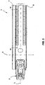
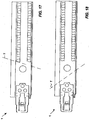
- a bar for making a support frame of a support structure of a false ceiling is denoted with the reference number 1.
- the bar is adapted to be joined to another metal bar 1 through a clip 2 fixed to one end of the metal bar 1.
- the clip 2 may be inserted into a slot (not shown) of a second metal bar 1 to be engaged with an edge that defines the slot in the metal bar 1 so as to create a join between two metal bars 1.
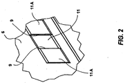
- the metal bar 1 has a "T"-shaped section, and is obtained by folding a sheet metal, so as to obtain an overlap of at least two sheet metal portions 5, 6.
- the metal bar 1 may be different from the one illustrated, for example, of different section, such as for example a "C"-shaped or "U”-shaped section, or even a further different "T"-shaped section.
- the metal bar 1 should include at least two sheet metal portions 5, 6, or walls, located side by side and/or overlapped, as shown for example in Figure 5 .
- the two sheet metal portions 5, 6 may be adherent on one another.
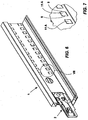
- the metal bar 1 extends in a prevailing direction, also called longitudinal direction, which is denoted by a dotted line in Figure 3 and in the non-claimed embodiment of Figure 8 , and denoted by reference letter L.
- the metal bar is an elongated body wherein a long side extending in said longitudinal direction and a short side, extending transversely with respect to the long side, are distinguished.
- transverse direction T which, looking at Figures 3 and 8 , goes from a long side to the other long side of the bar
- traverses, crosses or intersects the longitudinal direction and which as a result goes from a base area 8 (first long side) of the metal bar 1 to a top area 7 of the metal bar 1.
- transverse direction T can be meant as a direction orthogonal to the longitudinal direction L, or be meant as a direction extending in an oblique way and therefore forming an acute angle with the longitudinal direction L, in a direction of the bar short side.
- the oblique transverse direction T is indicated in Figures 17 and 18 .
- the transverse direction T can be partially curve as shown in Figure 19 , or completely curve.
- the two sheet metal portions 5, 6 includes one or more half-cut areas, i.e. incomplete cut areas, wherein the half-cut extends in the transverse direction T of the metal bar 1. More particularly, the two sheet metal portions 5, 6 includes one or more parts 10, 10A, 11, 11A partially sheared through a partial cut i.e. by one or more cuts 9 which determines a shifting with bending of that part 10, 10A, 11, 11A of a sheet metal portion 5, 6 towards the other sheet metal portion 5, 6. Such part 10, 10A, 11, 11A of a sheet metal portion 5, 6 is shifted so as to protrude and interfere with the other sheet metal portion 5.6.
- the cuts 9 carried out in the transverse direction T are such as to determine a shifting or bending of the partially cut part 10, 10A, 11, 11A of at least one of the sheet metal portions 5, 6 towards the other sheet metal portion 5, 6, and a consequent projection towards the other sheet metal portion 5, 6.
- the interference of a half-cut part towards the other sheet metal portion can occur on all the cut 9, or only in a bending zone, for example in a comer zone of the half-cut part.
- one of the two sheet metal portions 5, 6 includes a part 10, 10A, 11, 11A, which being partially cut, is shifted towards the other sheet metal portion 5, 6. It follows that the partially cut part 10, 10A, 11, 11A of one of the sheet metal portions 5, 6 is able to interfere with the other sheet metal portion 5, 6, and such interference occurs, or extends, mainly in a transverse direction T.
- Interference in this transverse direction T allows minimizing a possibility of torsion of the metal bar 1 around an axis parallel to the longitudinal direction L, with respect to bars of the same material and thickness of sheet metal or other characteristics of the metal bar, like elastic limit and tensile strength.
- the extension of the cuts 9 in the transverse direction of the metal bar 1 determines the making of half-sheared parts protruding in said transverse direction.
- Such half-sheared parts therefore create projections in the transverse direction and a consequent interference that is able to create an effective obstacle to a slip between the two sheet metal portions 5, 6, and consequently an effective impediment to a torsion of the bar around an axis parallel to the longitudinal direction L.
- each of the two sheet metal portions 5, 6 comprises cuts 9 defining the partially sheared parts 10, 10A, 11, 11A, i.e. obtained through a partial cut.
- each sheet metal portion 5, 6 has pairs of adjacent cuts 9, wherein each of said pairs of cuts 9 defines the part 10, 10A, 11, 11A (half-sheared or half-cut part 10, 10A, 11, 11A)
- the pairs of cuts 9 of one of the two sheet metal portions 5, 6 alternate with respect to the pair of cuts of the other of the two sheet metal portions.
- the cuts 9 are made in pairs, alternatively on one side and on the other side of the bar, so as to form pairs of staggered cuts.
- the two sheet metal portions 5, 6 have pairs of adjacent / staggered cuts in said longitudinal direction L and on opposite sides.
- Such cuts 9 determine an alternate shifting in opposite directions of pairs of partially cut parts, as shown in Figure 5 . This alternate shifting allows obtaining an increased interference between the parts.
- each of said sheet metal portions 5, 6 has a thickness S such that a direction crossing the thickness S is a thickness direction DS.
- the partially cut parts 10, 10A, 11, 11A are overlapped in said thickness direction DS and are shifted in pairs in the thickness direction DS with respect to an adjacent area of the respective sheet metal portion 5, 6.
- the partially cut parts 10, 10A, 11, 11A are shifted in pairs in the thickness direction DS and one of the partially shifted parts 10A, 11A is protruding towards the outside with respect to said thickness S and defines a free area in said thickness S.
- the other of said partially cut parts 10, 11 is arranged at least partially in the free area of the thickness S of the one sheet metal portion 5, 6, so as to create the interference in the longitudinal direction and in the transverse direction. Such interference allows obtaining a satisfactory locking to torsion.
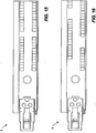
- only one of the two sheet metal portions 5, 6 includes the cuts 9 defining the partially cut parts 10 (sheared through a partial cut) which determine a shifting and possible cut of a corresponding part 11 A of the other sheet metal portion.
- a single sheet metal portion 5, 6 has one or more, for example pairs of adjacent cuts 9, wherein each of said pairs of cuts 9 defines pairs of parts 10, 11A.
- the pairs of cuts 9 of one of the two sheet metal portions 5, 6 are made at intervals along the longitudinal direction at a constant pitch, or with determinate pitch, so as to define a plurality of pairs of cuts 9
- the pairs of parts 10, 11A follow one another spaced at regular intervals.
- the pairs of parts 10, 11A alternate to parts 110, 111 of the two sheet metal portions 5, 6 which are not cut, i.e. not subjected to working.
- the spacing between subsequent pairs 10, 110, 11 A, 111, denoted with I in Figure 10 corresponds, for example, to the mutual distance between the two cuts 9 of each pair.
- pairs of cuts 9 are made only on one side of the bar, at more or less regular intervals.
- the cuts 9 determine a shift in the same direction of the parts 10, 11A.
- each of said sheet metal portions 5, 6 has a thickness S such that a direction crossing the thickness S is a thickness direction DS.
- the partially cut parts 10, 11A of Figure 10 are overlapped in said thickness direction DS and are shifted in pairs in the thickness direction DS with respect to an adjacent area of the respective sheet metal portion 5, 6.
- the partially cut parts 10, 11A are shifted in pairs in the thickness direction S and one of the partially shifted parts 11A is protruding towards the outside with respect to said thickness S and defines a free area in said thickness S.
- the other of said parts 10 is arranged at least partially in the free area of the thickness S, so as to create interference between the sheet metal portions 5, 6.
- the cuts 9 define a sequence or series of half-cut parts 10, 10A, 11, 11 A, which alternate continuously or at intervals, so as to make a half-cut line.
- Such half-cut line is also called, in the field of bars, seam line or seam.
- the seam line 15 or half-cut line can be in turn continue, as shown in Figure 1 , Figure 17 , Figure 18 or Figure 19 , or it can be a broken line, or a dotted line, as shown in Figure 14 , Figure 15 or Figure 16 .
- the metal bar 1 may include two or more series or half-cut lines 15 arranged on two different levels in said transverse direction, comprised between the base area 8 and the top area 7, as shown by way of example in Figure 14 , Figure 15 or Figure 16 .
- each cut 9 extends to a depth that is lower or equal to half the thickness S of the sheet metal portion 5, 6.
- each cut 9 extends to a depth that is equal to the thickness S of the sheet metal portion 5, 6.
- each cut 9 extends to a depth which is greater than the thickness S of the sheet metal portion 5, 6.
- the depth or penetration of the cut 9 with respect to the thickness is chosen according to the interference capacity (and therefore the ability of locking in torsion) between the two sheet metal portions 5, 6 to be obtained, and depends on the thickness of each sheet metal portion 5, 6, on the material of the sheet metal portion 5, 6, on its elastic limit and on its tensile strength, or on the presence of possible surface processing present on the faces of the sheet metal portions 5, 6.
- a working process for working a metal bar 1 according to an exemplary embodiment of the present invention is illustrated below. Such process may be used to make any of the bars described above.
- a metal bar 1 is provided having for example a T-shaped, section or another section and obtained by bending a sheet metal, so as to have a pair of portions or sheet metal walls 5, 6 overlapped.
- One, both; or more, portions or sheet metal walls 5, 6 are subjected to partial cut by means of a device known to a person skilled in the art, suitable for making partial cut of sheet metal.
- the partial cut is performed so as to make staggered pairs of cuts 9 on opposite sides of the two sheet metal portions 5, on the one of the two portions of sheet metal 5, 6 towards the other of the two portions of sheet metal 5, 6, such as those visible in Figure 5 , or pairs of cuts 9 at regular distances as those of the embodiment of figure 10 , which does not form part of the present invention, on only one of the two sheet metal portions 5, 6, or pairs of cuts as in any one of the embodiments of Figures 14-19 .
- These cuts 9 extend, i.e. are directed, in the transverse direction T of the metal bar 1.
- the half-cut is made so as to define pairs of half-cut parts 10, 10A, 11, 11 A, which in the exemplary embodiment of Figure 5 alternate continuously in the longitudinal direction and pairs of parts 10, 11A which in the exemplary embodiment of Figure 10 , which does not form part of the present invention, are arranged at regular intervals in the longitudinal direction. Thanks to the half-cut in the transverse direction it is determined an intersection in the transverse direction and in the longitudinal direction between the two sheet metal portions 5, 6 which prevents a sliding between them.
- the shape, or profile, of the parts 10, 10A, 11, 11A is not to be considered essential to the present invention.
- Many shapes or different profiles of half-sheared parts can be provided, as shown in Figures 14-19 . It is important that the half-cut is performed to art avoiding that any play resulting from the manufacturing are very much reduced, and an interference between the parts is assured.
Applications Claiming Priority (1)
| Application Number | Priority Date | Filing Date | Title |
|---|---|---|---|
| PCT/IB2012/053862 WO2014016648A1 (en) | 2012-07-27 | 2012-07-27 | Bar for a support structure for a false ceiling and production process for producing the bar |
Publications (2)
| Publication Number | Publication Date |
|---|---|
| EP2877643A1 EP2877643A1 (en) | 2015-06-03 |
| EP2877643B1 true EP2877643B1 (en) | 2016-05-18 |
Family
ID=46800232
Family Applications (1)
| Application Number | Title | Priority Date | Filing Date |
|---|---|---|---|
| EP12756033.2A Active EP2877643B1 (en) | 2012-07-27 | 2012-07-27 | Bar for a support structure for a false ceiling and production process for producing the bar |
Country Status (15)
| Country | Link |
|---|---|
| US (1) | US9376811B2 (zh) |
| EP (1) | EP2877643B1 (zh) |
| CN (1) | CN104641054B (zh) |
| AU (1) | AU2012386216B2 (zh) |
| BR (1) | BR112015001863B1 (zh) |
| CA (1) | CA2880116C (zh) |
| DK (1) | DK2877643T3 (zh) |
| ES (1) | ES2584390T3 (zh) |
| IL (1) | IL236591B (zh) |
| MX (1) | MX358936B (zh) |
| PL (1) | PL2877643T3 (zh) |
| PT (1) | PT2877643T (zh) |
| RU (1) | RU2601640C2 (zh) |
| WO (1) | WO2014016648A1 (zh) |
| ZA (1) | ZA201501342B (zh) |
Families Citing this family (5)
| Publication number | Priority date | Publication date | Assignee | Title |
|---|---|---|---|---|
| MY170877A (en) | 2011-11-11 | 2019-09-11 | Giuseppe Cipriani | Support metal structure for a false ceiling |
| RU2601640C2 (ru) | 2012-07-27 | 2016-11-10 | Джузеппе ЧИПРИАНИ | Рейка для поддерживающей конструкции подвесного потолка и способ обработки рейки |
| ITVR20130040A1 (it) | 2013-02-14 | 2014-08-15 | Giuseppe Cipriani | Struttura metallica di supporto di un controsoffitto. |
| ITVR20130058A1 (it) | 2013-03-08 | 2014-09-09 | Giuseppe Cipriani | Profilato di una struttura di supporto di un controsoffitto e procedimento di lavorazione per lavorare il profilato. |
| US11053682B1 (en) * | 2020-03-12 | 2021-07-06 | Usg Interiors, Llc | High strength main tee splice |
Family Cites Families (48)
| Publication number | Priority date | Publication date | Assignee | Title |
|---|---|---|---|---|
| US1253216A (en) * | 1915-05-03 | 1918-01-15 | Whitaker Glessner Company | Metal furring-strip. |
| US3312488A (en) | 1964-04-14 | 1967-04-04 | Lickliter | Expansion joint and locking connection for supporting grid systems |
| US3321879A (en) | 1964-08-05 | 1967-05-30 | W J Haertel & Co | Ceiling support structure with collapsible joint clip |
| GB1068380A (en) * | 1964-10-28 | 1967-05-10 | Donn Prod Inc | Structural beam |
| US3396997A (en) | 1966-03-24 | 1968-08-13 | Rollform Inc | Fire-rated ceiling grid system |
| US3501185A (en) | 1966-07-11 | 1970-03-17 | Donn Prod Inc | Cross beam connector |
| US3606417A (en) | 1970-03-26 | 1971-09-20 | Questor Corp | Ceiling suspension |
| US3746379A (en) | 1971-09-09 | 1973-07-17 | Flangeklamp Corp | Locking connection for supporting grid systems |
| GB1369234A (en) | 1972-04-28 | 1974-10-02 | Whitehouse George Eng | Suspended ceilings |
| US3979874A (en) | 1972-11-24 | 1976-09-14 | Alabama Metal Industries Corporation | Suspended ceiling system and runner joints therefor |
| US3922829A (en) | 1973-09-14 | 1975-12-02 | Roblin Hope S Ind Inc | Locking connection for supporting grid systems |
| US3921365A (en) * | 1974-10-04 | 1975-11-25 | Armstrong Cork Co | Joint structure for suspended ceiling system member |
| AU4226878A (en) | 1977-12-07 | 1979-06-14 | Overseas Corp Ltd | Gridwork structures |
| US4489529A (en) * | 1983-01-17 | 1984-12-25 | Armstrong World Industries, Inc. | Reinforced ceiling runner |
| GB2145752B (en) | 1983-08-27 | 1986-10-29 | Phoenix Rollformed Sections Li | Suspension ceiling grids |
| DE3575386D1 (de) * | 1984-03-22 | 1990-02-22 | Eckold Vorrichtung | Durchsetzfuegeverfahren. |
| US5271202A (en) | 1992-05-12 | 1993-12-21 | Chicago Metallic Corporation | Suspended ceiling system with staked-on connectors |
| GB2274080B (en) | 1993-01-08 | 1995-09-06 | Armstrong World Ind Inc | Ceiling runners and process for producing same |
| US5517796A (en) | 1994-05-25 | 1996-05-21 | Usg Interiors, Inc. | Stab-in removable end connector |
| DE4431849A1 (de) * | 1994-09-07 | 1996-03-14 | Nagel Hans Joachim | Durchsetz-Fügeverfahren und Durchsetz-Fügewerkzeug |
| US5577313A (en) * | 1995-01-17 | 1996-11-26 | Guido; Anthony | Method and apparatus for joining deformable sheet stock |
| US6047511A (en) * | 1998-03-04 | 2000-04-11 | Usg Interiors, Inc. | Grid tee with integrally stitched web |
| US6138416A (en) | 1998-11-12 | 2000-10-31 | Worthington Armstrong Venture | Beam |
| US6351919B1 (en) * | 2000-07-01 | 2002-03-05 | Worthington Armstrong Venture | Compression relief section |
| RU16605U1 (ru) * | 2000-08-22 | 2001-01-20 | Закрытое акционерное общество "Аркада" | Конструкция подвесного потолка, основной, поперечный, угловой, наружный уголковый, внутренний уголковый, угловой f-образный и ступенчатый потолочные профили и подвесы (варианты) для него |
| US6523314B1 (en) | 2000-12-29 | 2003-02-25 | Usg Interiors, Inc. | Ceiling grid with resilient centering tabs |
| US6523313B2 (en) | 2001-03-06 | 2003-02-25 | Worthington Armstrong Venture | Main beam connection |
| EP1288322A1 (en) | 2001-08-29 | 2003-03-05 | Sidmar N.V. | An ultra high strength steel composition, the process of production of an ultra high strength steel product and the product obtained |
| US6722098B2 (en) * | 2002-02-21 | 2004-04-20 | Worthington Armstrong Venture | Beam for drywall ceiling |
| DE10211257B4 (de) * | 2002-03-13 | 2012-02-23 | Richter-System Gmbh & Co Kg | Verfahren zum mechanischen Verbinden von zwei Elementen aus Metall, bei welchem die beiden Elemente aus Metall zwischen einem einzigen Satz von zwei Walzen hindurchgeführt werden |
| US6729100B2 (en) | 2002-04-30 | 2004-05-04 | Usg Interiors, Inc. | Main tee splice |
| DE10326333A1 (de) * | 2003-06-11 | 2004-12-30 | Protektorwerk Florenz Maisch Gmbh & Co. Kg | Profilschiene und Verfahren zum Herstellen einer Profilschiene |
| US7278243B2 (en) | 2004-07-14 | 2007-10-09 | Worthington Armstrong Venture | Molding for suspended panel ceiling |
| US7703258B2 (en) | 2005-05-23 | 2010-04-27 | Usg Interiors, Inc. | Main tee connection |
| US20070028554A1 (en) * | 2005-08-05 | 2007-02-08 | James Ferrell | High strength runner |
| ITVE20050046A1 (it) * | 2005-10-03 | 2007-04-04 | Dallan Spa | Procedimento di aggraffiatura di profilati a t, apparecchiatura per attuare il procedimento e profilato ottenuto con il procedimento.- |
| US7797903B2 (en) | 2005-11-21 | 2010-09-21 | Usg Interiors, Inc. | Compressed dovetail lance |
| CN201011018Y (zh) * | 2007-02-15 | 2008-01-23 | 林伟汛 | 龙骨的连接结构 |
| US7669374B2 (en) | 2007-04-03 | 2010-03-02 | Worthington Armstrong Venture | Beam for a drywall ceiling soffit |
| US7762034B2 (en) * | 2008-09-26 | 2010-07-27 | Chicago Metallic Corporation | Rotary stitch for joining sheet metal stock |
| CN201318008Y (zh) * | 2008-11-04 | 2009-09-30 | 蔡金河 | 墙体竖龙骨和吊顶覆面龙骨 |
| CN202194293U (zh) * | 2011-05-13 | 2012-04-18 | 李委 | T型立体凹槽贯通龙骨 |
| PL2532799T3 (pl) * | 2011-06-10 | 2015-11-30 | Knauf Amf Gmbh & Co Kg | Dźwigar metalowy i jego wykorzystanie |
| CN202176044U (zh) * | 2011-06-22 | 2012-03-28 | 万海雄 | 高间隔龙骨结构 |
| US8584418B2 (en) | 2011-09-09 | 2013-11-19 | Usg Interiors, Llc | Cross runner connector and main runner receiving hole |
| MY170877A (en) | 2011-11-11 | 2019-09-11 | Giuseppe Cipriani | Support metal structure for a false ceiling |
| US8590248B2 (en) * | 2012-04-20 | 2013-11-26 | Usg Interiors, Llc | Indexing tab for grid runners |
| RU2601640C2 (ru) | 2012-07-27 | 2016-11-10 | Джузеппе ЧИПРИАНИ | Рейка для поддерживающей конструкции подвесного потолка и способ обработки рейки |
-
2012
- 2012-07-27 RU RU2015106794/03A patent/RU2601640C2/ru active
- 2012-07-27 CA CA2880116A patent/CA2880116C/en active Active
- 2012-07-27 WO PCT/IB2012/053862 patent/WO2014016648A1/en active Application Filing
- 2012-07-27 EP EP12756033.2A patent/EP2877643B1/en active Active
- 2012-07-27 BR BR112015001863-7A patent/BR112015001863B1/pt not_active IP Right Cessation
- 2012-07-27 MX MX2015000994A patent/MX358936B/es active IP Right Grant
- 2012-07-27 CN CN201280074846.9A patent/CN104641054B/zh not_active Expired - Fee Related
- 2012-07-27 AU AU2012386216A patent/AU2012386216B2/en active Active
- 2012-07-27 ES ES12756033.2T patent/ES2584390T3/es active Active
- 2012-07-27 PT PT127560332T patent/PT2877643T/pt unknown
- 2012-07-27 PL PL12756033.2T patent/PL2877643T3/pl unknown
- 2012-07-27 US US14/412,666 patent/US9376811B2/en active Active
- 2012-07-27 DK DK12756033.2T patent/DK2877643T3/en active
-
2015
- 2015-01-05 IL IL236591A patent/IL236591B/en active IP Right Grant
- 2015-02-27 ZA ZA2015/01342A patent/ZA201501342B/en unknown
Also Published As
| Publication number | Publication date |
|---|---|
| CN104641054A (zh) | 2015-05-20 |
| CA2880116A1 (en) | 2014-01-30 |
| IL236591A0 (en) | 2015-02-26 |
| MX2015000994A (es) | 2015-11-23 |
| US20160002921A1 (en) | 2016-01-07 |
| ZA201501342B (en) | 2016-01-27 |
| RU2601640C2 (ru) | 2016-11-10 |
| PL2877643T3 (pl) | 2016-11-30 |
| AU2012386216A1 (en) | 2015-01-29 |
| ES2584390T3 (es) | 2016-09-27 |
| RU2015106794A (ru) | 2016-09-20 |
| BR112015001863A2 (pt) | 2017-07-04 |
| MX358936B (es) | 2018-09-10 |
| NZ703598A (en) | 2017-01-27 |
| WO2014016648A1 (en) | 2014-01-30 |
| CN104641054B (zh) | 2016-10-26 |
| CA2880116C (en) | 2019-06-11 |
| AU2012386216B2 (en) | 2017-08-31 |
| BR112015001863B1 (pt) | 2018-11-06 |
| IL236591B (en) | 2018-06-28 |
| EP2877643A1 (en) | 2015-06-03 |
| DK2877643T3 (en) | 2016-08-22 |
| US9376811B2 (en) | 2016-06-28 |
| PT2877643T (pt) | 2016-07-29 |
Similar Documents
| Publication | Publication Date | Title |
|---|---|---|
| EP2877643B1 (en) | Bar for a support structure for a false ceiling and production process for producing the bar | |
| EP2655224B1 (en) | Improved lateral plate element for a link means included in a self-stacking endless conveyor belt | |
| EP0279798B1 (en) | Profiled sheet for building purposes | |
| EP2964850B1 (en) | Bar of a support structure for a false ceiling and working process for working the bar | |
| NO331926B1 (no) | Profilert skinne og fremgangsmate for fremstilling av en profilert skinne | |
| US7797903B2 (en) | Compressed dovetail lance | |
| RO103630B1 (en) | Profiled bar | |
| NZ703598B2 (en) | Bar for a support structure for a false ceiling and production process for producing the bar | |
| JP2014167205A (ja) | 耐力壁 | |
| EP2412276A1 (en) | Improved shelf for shelving units | |
| EP2728083A1 (en) | Construction element | |
| WO1987004747A1 (en) | Sheet metal section, especially for roof, wall or floor structures |
Legal Events
| Date | Code | Title | Description |
|---|---|---|---|
| PUAI | Public reference made under article 153(3) epc to a published international application that has entered the european phase |
Free format text: ORIGINAL CODE: 0009012 |
|
| GRAP | Despatch of communication of intention to grant a patent |
Free format text: ORIGINAL CODE: EPIDOSNIGR1 |
|
| 17P | Request for examination filed |
Effective date: 20150216 |
|
| AK | Designated contracting states |
Kind code of ref document: A1 Designated state(s): AL AT BE BG CH CY CZ DE DK EE ES FI FR GB GR HR HU IE IS IT LI LT LU LV MC MK MT NL NO PL PT RO RS SE SI SK SM TR |
|
| AX | Request for extension of the european patent |
Extension state: BA ME |
|
| INTG | Intention to grant announced |
Effective date: 20150529 |
|
| DAX | Request for extension of the european patent (deleted) | ||
| INTG | Intention to grant announced |
Effective date: 20151207 |
|
| GRAS | Grant fee paid |
Free format text: ORIGINAL CODE: EPIDOSNIGR3 |
|
| GRAA | (expected) grant |
Free format text: ORIGINAL CODE: 0009210 |
|
| AK | Designated contracting states |
Kind code of ref document: B1 Designated state(s): AL AT BE BG CH CY CZ DE DK EE ES FI FR GB GR HR HU IE IS IT LI LT LU LV MC MK MT NL NO PL PT RO RS SE SI SK SM TR |
|
| REG | Reference to a national code |
Ref country code: GB Ref legal event code: FG4D |
|
| REG | Reference to a national code |
Ref country code: CH Ref legal event code: EP |
|
| REG | Reference to a national code |
Ref country code: AT Ref legal event code: REF Ref document number: 800618 Country of ref document: AT Kind code of ref document: T Effective date: 20160615 Ref country code: IE Ref legal event code: FG4D |
|
| REG | Reference to a national code |
Ref country code: DE Ref legal event code: R096 Ref document number: 602012018635 Country of ref document: DE |
|
| REG | Reference to a national code |
Ref country code: RO Ref legal event code: EPE |
|
| REG | Reference to a national code |
Ref country code: PT Ref legal event code: SC4A Ref document number: 2877643 Country of ref document: PT Date of ref document: 20160729 Kind code of ref document: T Free format text: AVAILABILITY OF NATIONAL TRANSLATION Effective date: 20160721 Ref country code: FR Ref legal event code: PLFP Year of fee payment: 5 |
|
| REG | Reference to a national code |
Ref country code: NL Ref legal event code: FP |
|
| REG | Reference to a national code |
Ref country code: CH Ref legal event code: NV Representative=s name: PATENTANWAELTE SCHAAD, BALASS, MENZL AND PARTN, CH |
|
| REG | Reference to a national code |
Ref country code: SE Ref legal event code: TRGR |
|
| REG | Reference to a national code |
Ref country code: DK Ref legal event code: T3 Effective date: 20160816 |
|
| REG | Reference to a national code |
Ref country code: LT Ref legal event code: MG4D |
|
| REG | Reference to a national code |
Ref country code: ES Ref legal event code: FG2A Ref document number: 2584390 Country of ref document: ES Kind code of ref document: T3 Effective date: 20160927 |
|
| REG | Reference to a national code |
Ref country code: NO Ref legal event code: T2 Effective date: 20160518 |
|
| PG25 | Lapsed in a contracting state [announced via postgrant information from national office to epo] |
Ref country code: LT Free format text: LAPSE BECAUSE OF FAILURE TO SUBMIT A TRANSLATION OF THE DESCRIPTION OR TO PAY THE FEE WITHIN THE PRESCRIBED TIME-LIMIT Effective date: 20160518 |
|
| PG25 | Lapsed in a contracting state [announced via postgrant information from national office to epo] |
Ref country code: LV Free format text: LAPSE BECAUSE OF FAILURE TO SUBMIT A TRANSLATION OF THE DESCRIPTION OR TO PAY THE FEE WITHIN THE PRESCRIBED TIME-LIMIT Effective date: 20160518 Ref country code: RS Free format text: LAPSE BECAUSE OF FAILURE TO SUBMIT A TRANSLATION OF THE DESCRIPTION OR TO PAY THE FEE WITHIN THE PRESCRIBED TIME-LIMIT Effective date: 20160518 Ref country code: HR Free format text: LAPSE BECAUSE OF FAILURE TO SUBMIT A TRANSLATION OF THE DESCRIPTION OR TO PAY THE FEE WITHIN THE PRESCRIBED TIME-LIMIT Effective date: 20160518 |
|
| PG25 | Lapsed in a contracting state [announced via postgrant information from national office to epo] |
Ref country code: EE Free format text: LAPSE BECAUSE OF FAILURE TO SUBMIT A TRANSLATION OF THE DESCRIPTION OR TO PAY THE FEE WITHIN THE PRESCRIBED TIME-LIMIT Effective date: 20160518 Ref country code: SK Free format text: LAPSE BECAUSE OF FAILURE TO SUBMIT A TRANSLATION OF THE DESCRIPTION OR TO PAY THE FEE WITHIN THE PRESCRIBED TIME-LIMIT Effective date: 20160518 Ref country code: CZ Free format text: LAPSE BECAUSE OF FAILURE TO SUBMIT A TRANSLATION OF THE DESCRIPTION OR TO PAY THE FEE WITHIN THE PRESCRIBED TIME-LIMIT Effective date: 20160518 |
|
| REG | Reference to a national code |
Ref country code: GR Ref legal event code: EP Ref document number: 20160401783 Country of ref document: GR Effective date: 20161020 |
|
| REG | Reference to a national code |
Ref country code: DE Ref legal event code: R097 Ref document number: 602012018635 Country of ref document: DE |
|
| PG25 | Lapsed in a contracting state [announced via postgrant information from national office to epo] |
Ref country code: SM Free format text: LAPSE BECAUSE OF FAILURE TO SUBMIT A TRANSLATION OF THE DESCRIPTION OR TO PAY THE FEE WITHIN THE PRESCRIBED TIME-LIMIT Effective date: 20160518 |
|
| PLBE | No opposition filed within time limit |
Free format text: ORIGINAL CODE: 0009261 |
|
| STAA | Information on the status of an ep patent application or granted ep patent |
Free format text: STATUS: NO OPPOSITION FILED WITHIN TIME LIMIT |
|
| 26N | No opposition filed |
Effective date: 20170221 |
|
| PG25 | Lapsed in a contracting state [announced via postgrant information from national office to epo] |
Ref country code: SI Free format text: LAPSE BECAUSE OF FAILURE TO SUBMIT A TRANSLATION OF THE DESCRIPTION OR TO PAY THE FEE WITHIN THE PRESCRIBED TIME-LIMIT Effective date: 20160518 |
|
| REG | Reference to a national code |
Ref country code: FR Ref legal event code: PLFP Year of fee payment: 6 |
|
| REG | Reference to a national code |
Ref country code: AT Ref legal event code: UEP Ref document number: 800618 Country of ref document: AT Kind code of ref document: T Effective date: 20160518 |
|
| PG25 | Lapsed in a contracting state [announced via postgrant information from national office to epo] |
Ref country code: HU Free format text: LAPSE BECAUSE OF FAILURE TO SUBMIT A TRANSLATION OF THE DESCRIPTION OR TO PAY THE FEE WITHIN THE PRESCRIBED TIME-LIMIT; INVALID AB INITIO Effective date: 20120727 |
|
| PG25 | Lapsed in a contracting state [announced via postgrant information from national office to epo] |
Ref country code: MK Free format text: LAPSE BECAUSE OF FAILURE TO SUBMIT A TRANSLATION OF THE DESCRIPTION OR TO PAY THE FEE WITHIN THE PRESCRIBED TIME-LIMIT Effective date: 20160518 Ref country code: CY Free format text: LAPSE BECAUSE OF FAILURE TO SUBMIT A TRANSLATION OF THE DESCRIPTION OR TO PAY THE FEE WITHIN THE PRESCRIBED TIME-LIMIT Effective date: 20160518 Ref country code: IS Free format text: LAPSE BECAUSE OF FAILURE TO SUBMIT A TRANSLATION OF THE DESCRIPTION OR TO PAY THE FEE WITHIN THE PRESCRIBED TIME-LIMIT Effective date: 20160518 |
|
| REG | Reference to a national code |
Ref country code: FR Ref legal event code: PLFP Year of fee payment: 7 |
|
| PG25 | Lapsed in a contracting state [announced via postgrant information from national office to epo] |
Ref country code: BG Free format text: LAPSE BECAUSE OF FAILURE TO SUBMIT A TRANSLATION OF THE DESCRIPTION OR TO PAY THE FEE WITHIN THE PRESCRIBED TIME-LIMIT Effective date: 20160518 |
|
| PG25 | Lapsed in a contracting state [announced via postgrant information from national office to epo] |
Ref country code: AL Free format text: LAPSE BECAUSE OF FAILURE TO SUBMIT A TRANSLATION OF THE DESCRIPTION OR TO PAY THE FEE WITHIN THE PRESCRIBED TIME-LIMIT Effective date: 20160518 |
|
| PGFP | Annual fee paid to national office [announced via postgrant information from national office to epo] |
Ref country code: LU Payment date: 20190722 Year of fee payment: 9 Ref country code: RO Payment date: 20190624 Year of fee payment: 8 |
|
| PGFP | Annual fee paid to national office [announced via postgrant information from national office to epo] |
Ref country code: PT Payment date: 20190725 Year of fee payment: 8 Ref country code: IE Payment date: 20190724 Year of fee payment: 8 Ref country code: FI Payment date: 20190722 Year of fee payment: 8 Ref country code: DK Payment date: 20190723 Year of fee payment: 8 Ref country code: MC Payment date: 20190712 Year of fee payment: 8 |
|
| PGFP | Annual fee paid to national office [announced via postgrant information from national office to epo] |
Ref country code: GR Payment date: 20190716 Year of fee payment: 8 |
|
| PGFP | Annual fee paid to national office [announced via postgrant information from national office to epo] |
Ref country code: AT Payment date: 20190722 Year of fee payment: 8 |
|
| PGFP | Annual fee paid to national office [announced via postgrant information from national office to epo] |
Ref country code: CH Payment date: 20190719 Year of fee payment: 8 |
|
| PGFP | Annual fee paid to national office [announced via postgrant information from national office to epo] |
Ref country code: NO Payment date: 20200723 Year of fee payment: 9 |
|
| PGFP | Annual fee paid to national office [announced via postgrant information from national office to epo] |
Ref country code: SE Payment date: 20200727 Year of fee payment: 9 |
|
| REG | Reference to a national code |
Ref country code: FI Ref legal event code: MAE |
|
| PG25 | Lapsed in a contracting state [announced via postgrant information from national office to epo] |
Ref country code: MC Free format text: LAPSE BECAUSE OF NON-PAYMENT OF DUE FEES Effective date: 20200731 |
|
| REG | Reference to a national code |
Ref country code: CH Ref legal event code: PL |
|
| REG | Reference to a national code |
Ref country code: DK Ref legal event code: EBP Effective date: 20200731 |
|
| REG | Reference to a national code |
Ref country code: AT Ref legal event code: MM01 Ref document number: 800618 Country of ref document: AT Kind code of ref document: T Effective date: 20200727 |
|
| PG25 | Lapsed in a contracting state [announced via postgrant information from national office to epo] |
Ref country code: CH Free format text: LAPSE BECAUSE OF NON-PAYMENT OF DUE FEES Effective date: 20200731 Ref country code: GR Free format text: LAPSE BECAUSE OF NON-PAYMENT OF DUE FEES Effective date: 20210210 Ref country code: LI Free format text: LAPSE BECAUSE OF NON-PAYMENT OF DUE FEES Effective date: 20200731 Ref country code: PT Free format text: LAPSE BECAUSE OF NON-PAYMENT OF DUE FEES Effective date: 20210301 Ref country code: LU Free format text: LAPSE BECAUSE OF NON-PAYMENT OF DUE FEES Effective date: 20200727 Ref country code: FI Free format text: LAPSE BECAUSE OF NON-PAYMENT OF DUE FEES Effective date: 20200727 Ref country code: RO Free format text: LAPSE BECAUSE OF NON-PAYMENT OF DUE FEES Effective date: 20200727 |
|
| PG25 | Lapsed in a contracting state [announced via postgrant information from national office to epo] |
Ref country code: AT Free format text: LAPSE BECAUSE OF NON-PAYMENT OF DUE FEES Effective date: 20200727 |
|
| PG25 | Lapsed in a contracting state [announced via postgrant information from national office to epo] |
Ref country code: IE Free format text: LAPSE BECAUSE OF NON-PAYMENT OF DUE FEES Effective date: 20200727 Ref country code: DK Free format text: LAPSE BECAUSE OF NON-PAYMENT OF DUE FEES Effective date: 20200731 |
|
| PGFP | Annual fee paid to national office [announced via postgrant information from national office to epo] |
Ref country code: NL Payment date: 20210721 Year of fee payment: 10 |
|
| PGFP | Annual fee paid to national office [announced via postgrant information from national office to epo] |
Ref country code: TR Payment date: 20210727 Year of fee payment: 10 |
|
| REG | Reference to a national code |
Ref country code: NO Ref legal event code: MMEP |
|
| PG25 | Lapsed in a contracting state [announced via postgrant information from national office to epo] |
Ref country code: SE Free format text: LAPSE BECAUSE OF NON-PAYMENT OF DUE FEES Effective date: 20210728 Ref country code: NO Free format text: LAPSE BECAUSE OF NON-PAYMENT OF DUE FEES Effective date: 20210731 |
|
| PG25 | Lapsed in a contracting state [announced via postgrant information from national office to epo] |
Ref country code: MT Free format text: LAPSE BECAUSE OF NON-PAYMENT OF DUE FEES Effective date: 20200727 |
|
| REG | Reference to a national code |
Ref country code: NL Ref legal event code: MM Effective date: 20220801 |
|
| PG25 | Lapsed in a contracting state [announced via postgrant information from national office to epo] |
Ref country code: NL Free format text: LAPSE BECAUSE OF NON-PAYMENT OF DUE FEES Effective date: 20220801 |
|
| P01 | Opt-out of the competence of the unified patent court (upc) registered |
Effective date: 20230530 |
|
| PGFP | Annual fee paid to national office [announced via postgrant information from national office to epo] |
Ref country code: PL Payment date: 20230622 Year of fee payment: 12 |
|
| PGFP | Annual fee paid to national office [announced via postgrant information from national office to epo] |
Ref country code: IT Payment date: 20230704 Year of fee payment: 12 Ref country code: GB Payment date: 20230720 Year of fee payment: 12 Ref country code: ES Payment date: 20230926 Year of fee payment: 12 |
|
| PGFP | Annual fee paid to national office [announced via postgrant information from national office to epo] |
Ref country code: FR Payment date: 20230725 Year of fee payment: 12 Ref country code: DE Payment date: 20230719 Year of fee payment: 12 Ref country code: BE Payment date: 20230719 Year of fee payment: 12 |