US7278243B2 - Molding for suspended panel ceiling - Google Patents
Molding for suspended panel ceiling Download PDFInfo
- Publication number
- US7278243B2 US7278243B2 US11/226,506 US22650605A US7278243B2 US 7278243 B2 US7278243 B2 US 7278243B2 US 22650605 A US22650605 A US 22650605A US 7278243 B2 US7278243 B2 US 7278243B2
- Authority
- US
- United States
- Prior art keywords
- molding
- ledge
- tab
- flange
- tabs
- Prior art date
- Legal status (The legal status is an assumption and is not a legal conclusion. Google has not performed a legal analysis and makes no representation as to the accuracy of the status listed.)
- Active, expires
Links
Images


Classifications
-
- E—FIXED CONSTRUCTIONS
- E04—BUILDING
- E04B—GENERAL BUILDING CONSTRUCTIONS; WALLS, e.g. PARTITIONS; ROOFS; FLOORS; CEILINGS; INSULATION OR OTHER PROTECTION OF BUILDINGS
- E04B9/00—Ceilings; Construction of ceilings, e.g. false ceilings; Ceiling construction with regard to insulation
- E04B9/30—Ceilings; Construction of ceilings, e.g. false ceilings; Ceiling construction with regard to insulation characterised by edge details of the ceiling; e.g. securing to an adjacent wall
-
- E—FIXED CONSTRUCTIONS
- E04—BUILDING
- E04B—GENERAL BUILDING CONSTRUCTIONS; WALLS, e.g. PARTITIONS; ROOFS; FLOORS; CEILINGS; INSULATION OR OTHER PROTECTION OF BUILDINGS
- E04B9/00—Ceilings; Construction of ceilings, e.g. false ceilings; Ceiling construction with regard to insulation
- E04B9/06—Ceilings; Construction of ceilings, e.g. false ceilings; Ceiling construction with regard to insulation characterised by constructional features of the supporting construction, e.g. cross section or material of framework members
- E04B9/065—Ceilings; Construction of ceilings, e.g. false ceilings; Ceiling construction with regard to insulation characterised by constructional features of the supporting construction, e.g. cross section or material of framework members comprising supporting beams having a folded cross-section
- E04B9/067—Ceilings; Construction of ceilings, e.g. false ceilings; Ceiling construction with regard to insulation characterised by constructional features of the supporting construction, e.g. cross section or material of framework members comprising supporting beams having a folded cross-section with inverted T-shaped cross-section
- E04B9/068—Ceilings; Construction of ceilings, e.g. false ceilings; Ceiling construction with regard to insulation characterised by constructional features of the supporting construction, e.g. cross section or material of framework members comprising supporting beams having a folded cross-section with inverted T-shaped cross-section with double web
-
- E—FIXED CONSTRUCTIONS
- E04—BUILDING
- E04B—GENERAL BUILDING CONSTRUCTIONS; WALLS, e.g. PARTITIONS; ROOFS; FLOORS; CEILINGS; INSULATION OR OTHER PROTECTION OF BUILDINGS
- E04B9/00—Ceilings; Construction of ceilings, e.g. false ceilings; Ceiling construction with regard to insulation
- E04B9/06—Ceilings; Construction of ceilings, e.g. false ceilings; Ceiling construction with regard to insulation characterised by constructional features of the supporting construction, e.g. cross section or material of framework members
- E04B9/12—Connections between non-parallel members of the supporting construction
- E04B9/127—Connections between non-parallel members of the supporting construction one member being discontinuous and abutting against the other member
-
- E—FIXED CONSTRUCTIONS
- E04—BUILDING
- E04B—GENERAL BUILDING CONSTRUCTIONS; WALLS, e.g. PARTITIONS; ROOFS; FLOORS; CEILINGS; INSULATION OR OTHER PROTECTION OF BUILDINGS
- E04B9/00—Ceilings; Construction of ceilings, e.g. false ceilings; Ceiling construction with regard to insulation
- E04B9/06—Ceilings; Construction of ceilings, e.g. false ceilings; Ceiling construction with regard to insulation characterised by constructional features of the supporting construction, e.g. cross section or material of framework members
- E04B2009/062—Caps covering visible surfaces of the supporting construction
Definitions
- the invention relates to suspended panel ceilings, and more particularly to a wall molding that supports the ends of the beams that abut the walls surrounding such ceilings.
- the prior art includes suspended panel ceilings of a general construction and such suspended ceilings that also conform to seismic requirements.
- Panel suspended ceilings use spaced beams to support panels on flanges of the beams.
- the beams are rollformed from a strip of steel into an inverted T cross section with a bulb at the top, a web, and flanges extending horizontally from the bottom of the web.
- a bottom cover or cap extends over the bottom of the flanges, and then upward and inwardly along the edges of the flanges to form hems that secure the cap to the flanges.
- Main and cross beams are generally interconnected to form a grid having rectangular 2′ ⁇ 2′ or 2′ ⁇ 4′ openings for the panels.
- the beams are usually suspended with hanger wires embedded in a structural ceiling. The ends of the beams that abut the walls around the ceiling rest on ledges of angled wall moldings. The ledges of the wall moldings also support the panels along the walls.
- the beams that extend across the corridor may be supported only at their ends, on the ledges of the wall molding, without hanger wires.
- Such means include stabilizer bars that run along the wall molding to keep the ends of the beams from shaking in a direction parallel to the wall, and perimeter clips on the beams which keep the ends of the beams from shaking off the molding in a direction away from the wall.
- Two-inch wide ledges on the wall moldings may also be used in accordance with seismic requirements, instead of perimeter clips, to prevent the ends of the beams resting on the wall molding from falling off the ledge, away from the wall, during a quake.
- the wall molding of the present invention in a panel suspended ceiling, provides a quick and accurate way of positioning, and fixing, the end of a beam abutting a wall, on the ledge of a wall molding.
- the wall molding of the present invention is formed with a pair of retaining tabs, regularly spaced along the molding, lanced from the horizontal ledge of the molding, while the molding is being made.
- the pair of tabs work jointly, along with a single ratchet tooth in a tab in one embodiment, or a ratchet tooth in each tab in another embodiment, to position and lock the beam flanges to the ledge, by a single back and forth motion.
- the flanges are held downwardly against the ledge by the tabs, which are spring biased downwardly.
- the wall molding of the present invention has a cover, or cap, under the bottom of the wall molding ledge, to hide the lanced portions that form the tabs in the ledge.
- the cap is secured on the ledge by a hem that engages a detent on one side of the ledge, and by a hem that extends over the other side of the ledge.
- the angle of the wall molding of the invention can be made of heavier or stiffer metal than that of the cap that is fixed on the bottom of the horizontal ledge of the wall molding. Such heavier or stiffer metal in the angle can serve to keep the ledge stabilized in a flat plane, free of the distortion that often occurs when the vertical leg of the molding is secured to a wall with a wavering surface.
- the angle can be made without any color coating, and of a rougher and less expensive grade metal than the cap, since it is not seen by an observer from below.
- the cap which is the only visible part of the molding to an observer from below, is formed of metal with a smooth finish and a color coat. Such a molding then blends with the underside of the flanges of the beams in the ceiling. Such beams also have color coated caps. Such a two piece construction yields a strong and attractive molding at a minimum cost.
- a first flange that extends horizontally on one side of a beam is manually slid rearwardly under a hold-down tab until a second, oppositely extending, flange on the other side of the beam clears a forwardly positioned locking tab on the ledge. The motion of the beam is then reversed to move the second flange on the beam under the locking tab.
- the second flange with its upwardly extending hem, passes over a ratchet tooth in the locking tab, whereby the locking tab secures the second flange to the molding ledge, and the ratchet tooth on the locking tab prevents rearward movement, with both the first flange and second flange held downward in contact with the ledge by the downward spring bias of the tabs.
- each tab is associated with a ratchet tooth.
- the beam is locked to the wall molding at a predetermined position along the molding, in a quick and relatively easy manner.
- the opposite end of the beam is likewise positioned and locked to a wall molding on the opposing wall.
- the moldings on opposite walls are placed in exact opposite registry, so that the beams are positioned and secured in the moldings, parallel to one another, at selected, regularly spaced, intervals.
- the hold-down and locking tabs, and ratchet teeth are continuously lanced from the molding ledge with suitably designed, well-known, punching machinery.
- the present invention is particularly suited for seismic ceilings that support ends of both main beams and cross beams on wall moldings, as in a grid, regardless of whether the beams are primarily supported by hang wires in addition to the wall molding support, or whether supported by the wall molding alone.
- the wall moldings of the invention for seismic ceilings, use a 2′′ wide ledge, as in the prior art.
- the 2′′ ledge continues, in an earthquake, to support the ends of the beams as they shake toward and away from the perimeter wall. No perimeter clips are necessary.
- the tabs restrain the ends of the beam from moving along the perimeter wall, during a quake, whereby the beams then continue to maintain their positions to support panels, and prevent the panels from falling. This eliminates any need for the use of the stabilizer bars of the prior art.
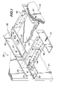
- FIG. 1 is a fragmented perspective view, from above, of a suspended ceiling extending between opposing walls, showing a first embodiment of the invention.
- FIG. 2 is a fragmented perspective view, taken from above, of the first flange of a beam being inserted under the rear hold-down tab of the connection, to form the embodiment of the invention shown in FIG. 1 .
- FIG. 3 is a cross-sectional view taken of the line 3 - 3 of FIG. 2 .
- FIG. 4 is a fragmented perspective view, similar to FIG. 2 , from above, showing the beam resting on the molding ledge, positioned fully rearward under the rear hold-down tab.
- FIG. 5 is a cross-sectional view, similar to FIG. 3 , taken on the line 5 - 5 of FIG. 4 .
- FIG. 6 is a fragmentary perspective view, similar to FIGS. 2 and 4 , showing the beam moved fully forward on the ledge 43 , beneath the hold-down 61 and locking 62 tabs, with the hem of the forward flange engaged with the ratchet tooth on the forward locking tab 62 , locking the beam in a forward position beneath the hold-down 61 and locking 62 tabs.
- FIG. 7 is a view similar to FIGS. 3 and 5 , taken on the line 7 - 7 of FIG. 6 .
- FIG. 8 is similar to FIG. 3 showing an embodiment wherein hold-down tab 61 has associated therewith a ratchet tooth 70 ′, and locking tab 62 ′ is as long as hold-down tab 61 .
- FIG. 9 is similar to FIG. 5 showing the beam 50 of FIG. 8 in a rearward position on the ledge 43 .
- FIG. 10 is a view similar to FIGS. 7 and 10 showing the beam 50 of FIG. 8 shifted forward to a locked position.
- FIG. 11 is a fragmented perspective view, from above, of a rollforming operation that forms an indent in the vertical leg of the angle wall molding, and rolls on a cap.
- FIG. 12 is a cross section of a fragment of a wall molding showing a hem on the ledge, formed from the ledge.
- a panel suspended ceiling 20 extends between opposing vertical room walls 21 and 22 .
- the ceiling 20 includes beams 50 supporting thereon panels 25 .
- the panels 25 rest on the flanges 53 , 55 of beams 50 .
- a wall molding 30 extends horizontally along walls 21 and 22 and is affixed thereton by self-tapping screws 27 .
- Beam 50 has a bulb 51 , web 52 , and flanges 53 and 55 extending horizontally at the bottom of web 52 .
- the beam 50 has a cap 54 that extends over flanges 53 and 55 , and is secured to the flanges by upwardly and inwardly extending hems 58 and 59 .
- Stitches 56 secure layers of web 52 together.
- Molding 30 has a vertical leg 42 and a horizontal ledge 43 .
- Main beams and cross beams are generally interconnected to form a ceiling grid that supports the panel.
- a wall molding 30 has spaced along the ledge 43 a pair of opposing tabs 61 and 62 .
- Tab 61 forms a hold-down tab that is lanced from the ledge 43 .
- Tongue 63 is biased downwardly toward the ledge 43 .
- the hold-down tab 61 is integral with the ledge 43 at its pivot line 65 and then has a straight section 68 and an upturned section 69 .
- locking tab 62 Positioned opposite to hold-down tab 61 is locking tab 62 .
- Tab 62 is similar to tab 61 except tongue 63 is shorter as shown.
- Extending downwardly from tongue 63 of the locking tab 62 is a ratchet tooth 70 which has a slope extending away from the hold-down tab 61 , toward the pivot line 71 of locking tab 62 .
- a cap 80 extends over the bottom of wall molding 30 so that the lanced portions of ledge 43 cannot be seen from below.
- the cap is desirably formed of a smooth finish metal that is color coated to match the caps of the bottom of the flanges of the beams in the ceiling.
- Such a cap 80 not only hides the lanced holes in ledge 43 , but also gives a decorative appearance to the molding, without the expense of making the entire molding of such smooth finish that is color coated.
- the cap 80 may be applied in a rollforming operation as seen in FIG. 11 .
- An indent 81 is first formed in the bottom of the vertical leg 42 where it joins ledge 43 .
- the indent 81 can be seen, for instance, in FIG. 2 .
- the indent 81 is formed by rolls 82 as the molding 30 travels in the direction 85 , after having tabs 61 and 62 formed in the ledge 43 by suitable punching means.
- the cap 80 on the bottom of the wall molding ledge 43 is desirably made of thinner metal than that of the angled vertical leg 42 and horizontal ledge 43 of the wall molding 30 , since the function of such cap 80 is primarily decorative to hide the lanced holes in ledge 43 , and to provide a surface appearance, including color, on the bottom of the molding that matches the surface and color of the cap on the bottom of the beams as constructed in the prior art.
- the molding 43 with the indent 81 formed therein passes between rollers 86 and 87 .
- a web 88 of cap metal is fed into the rollers 86 , 87 , which form hem 89 on one side of the ledge 43 , and hem 91 , which is formed about the indent 81 .
- a hem 93 that is integral with, and extends upwardly and inwardly from the ledge 43 when the molding 30 is in position on a wall.
- a hem further stiffens the ledge.
- hem 91 of the cap is rollformed over such ledge hem 93 .
- FIG. 12 Such a hem 93 on ledge 43 is shown in FIG. 12 .
- the completed molding 30 then advances to a cut-off station to be cut into suitable lengths.
- a typical wall molding 30 may have a vertical leg 42 and a ledge 43 , each 7 ⁇ 8′′ wide.
- Each of the tabs 61 , 62 may be 1 ⁇ 2′′ wide in a direction across the molding 30 , with a space of about 4 ⁇ 5′′ between a pair of opposing tabs 61 and 62 .
- the distance between the pivot lines 65 and 71 of the tabs 61 , 62 may be about 2′′.
- a channel wall molding may be used that is U-shaped in cross section, wherein the base of the U is attached vertically to the wall and acts as the vertical leg and the lower horizontal leg of the U acts as a ledge 43 .
- the beam 50 is engaged with the pair of tabs 61 and 62 and ratchet tooth 70 as seen in FIGS. 2 through 7 .
- first flange 53 of beam 50 is engaged under hold-down tab 61 as shown.
- the beam 50 with flanges 53 and 55 is angled so that first flange 53 can engage under the locking tab 62 as shown.
- Second flange 55 bears on top of locking tab 62 .
- Both hold-down tab 61 and locking tab 62 have a downward bias in the form of a spring action that results when the tabs 61 , 62 are lanced out of the steel web stock from which the angle moldings 30 are formed.
- the forming of angle molding by rollforming, and the steel used in the web from which the molding is formed, is well-known in the prior art.
- first flange 53 has been slid completely under hold-down tab 61
- second flange 55 has cleared locking tab 62 .
- Flanges 53 and 55 rest on ledge 43 and are held thereto by spring biasing action of hold down tab 61 .
- the hold-down tab 61 must have a length deep enough to permit the first flange 53 to slide rewardly enough to permit the second flange 55 to clear locking tab 62 .
- beam 50 With flanges 53 and 55 , is slid forward under locking tab 62 until hem 58 on the top side of flange 55 passes under ratchet tooth 70 . Second flange 55 is then forced downward against ledge 43 by locking tab 62 , whereby the flange 55 is locked in place from forward or rearward movement on ledge 43 .
- Hold-down tab 61 as seen in FIGS. 6 and 7 , holds down the first flange 53 against the ledge 43 .
- tab 62 ′ is extended in length to that of tab 61 , and an additional ratchet tooth 70 ′ that slopes downwardly away from tab 62 , is formed from tab 61 .
- the beam can be positioned in the tabs by a first movement in either direction, that is, initially toward tab 61 , or toward tab 62 ′.
- the first flange 53 can be first inserted under tab 61 until the hem 58 passes under ratchet tooth 70 ′.
- the beam 50 is then shifted in an opposite direction underneath tab 62 ′ until the hem 59 on the second flange 55 engages the ratchet tooth 70 , as seen in FIG. 10 .
- the beam 50 is kept from shifting forward and rearward by the combined action of the ratchet teeth 70 and 71 ′, and the tabs 61 and 62 ′.
- the flanges 53 and 55 are again downwardly secured against the ledge 43 by the downward spring bias of the tabs 61 and 62 ′.
- the above described positioning and locking actions at opposite ends of beam 50 may occur simultaneously, if for instance, an installer is positioned at each end of the beam 50 to perform the position and securing action as described.
- panels 25 of, for instance, acoustic material are positioned on the flanges of the beams 50 , to form the ceiling.
- a panel 25 is supported in position in the ceiling along a wall by the wall molding ledge 43 and the flanges 53 and 55 of beams 50 .
- a pair of tabs 61 and 62 are regularly spaced along the molding ledge 43 , at, for instance, 2′ intervals, so that the ends of beams 50 that abut a wall can be secured at selected distance to receive panels 25 .
- Beams 50 are locked in to wall moldings 30 that are in registry opposing walls, so that the beams 50 run across the ceiling parallel to one another.
- ledge 43 is extended to a 2′′ width.
- the end of beam 50 is cut so that at rest position on the ledge, as seen for instance in FIG. 1 , the end of the beam is 3 ⁇ 4′′ away from vertical leg 42 of molding 30 .
- This is in conformance generally with code requirements for a seismic ceiling.
- the end of the beam 50 can travel 3 ⁇ 4′′ away from its rest position toward or away from the wall 21 or 22 , and still be supported on the 2′′ ledge.
- the tabs 61 and 62 again extend along the beam 50 as described above, and keep the beam end from moving along the wall 21 , 22 during a quake.
Abstract
Description
Claims (18)
Priority Applications (7)
| Application Number | Priority Date | Filing Date | Title |
|---|---|---|---|
| US11/226,506 US7278243B2 (en) | 2004-07-14 | 2005-09-13 | Molding for suspended panel ceiling |
| AU2006203611A AU2006203611B9 (en) | 2005-09-13 | 2006-08-21 | Molding for suspended panel ceiling |
| CA002557451A CA2557451C (en) | 2005-09-13 | 2006-08-30 | Molding for suspended panel ceiling |
| EP06018329A EP1762663A1 (en) | 2005-09-13 | 2006-09-01 | Molding for suspended panel ceiling |
| BRPI0604190-6A BRPI0604190A (en) | 2005-09-13 | 2006-09-04 | grid to support panels in a suspended ceiling, and wall profile for a grid in a suspended ceiling |
| CN2006101515087A CN1932197B (en) | 2005-09-13 | 2006-09-12 | Molding for suspended panel ceiling |
| HK07105027.9A HK1097581A1 (en) | 2005-09-13 | 2007-05-11 | Molding for suspended panel ceiling |
Applications Claiming Priority (2)
| Application Number | Priority Date | Filing Date | Title |
|---|---|---|---|
| US10/890,436 US7240460B2 (en) | 2004-07-14 | 2004-07-14 | Molding for drywall ceiling grid |
| US11/226,506 US7278243B2 (en) | 2004-07-14 | 2005-09-13 | Molding for suspended panel ceiling |
Related Parent Applications (1)
| Application Number | Title | Priority Date | Filing Date |
|---|---|---|---|
| US10/890,436 Continuation-In-Part US7240460B2 (en) | 2004-07-14 | 2004-07-14 | Molding for drywall ceiling grid |
Publications (2)
| Publication Number | Publication Date |
|---|---|
| US20060010812A1 US20060010812A1 (en) | 2006-01-19 |
| US7278243B2 true US7278243B2 (en) | 2007-10-09 |
Family
ID=37189006
Family Applications (1)
| Application Number | Title | Priority Date | Filing Date |
|---|---|---|---|
| US11/226,506 Active 2024-11-13 US7278243B2 (en) | 2004-07-14 | 2005-09-13 | Molding for suspended panel ceiling |
Country Status (7)
| Country | Link |
|---|---|
| US (1) | US7278243B2 (en) |
| EP (1) | EP1762663A1 (en) |
| CN (1) | CN1932197B (en) |
| AU (1) | AU2006203611B9 (en) |
| BR (1) | BRPI0604190A (en) |
| CA (1) | CA2557451C (en) |
| HK (1) | HK1097581A1 (en) |
Cited By (16)
| Publication number | Priority date | Publication date | Assignee | Title |
|---|---|---|---|---|
| US20050217194A1 (en) * | 2004-03-30 | 2005-10-06 | Eric Krantz-Lilienthal | Trim system for a suspended ceiling |
| US20070113507A1 (en) * | 2005-11-21 | 2007-05-24 | Lehane James J Jr | Compressed dovetail lance |
| US20080209833A1 (en) * | 2007-03-01 | 2008-09-04 | Ulrich Conradi | Facing system for building constructions with two-dimensionally and/or spherically shaped regions to be faced |
| US20080229680A1 (en) * | 2007-03-21 | 2008-09-25 | Jahn Peter G | Wall angle with pre-punched locating tabs |
| WO2009094698A1 (en) * | 2008-01-30 | 2009-08-06 | Top Idea Australia Pty Ltd | Modular angle trim |
| EP2130988A2 (en) | 2008-06-04 | 2009-12-09 | Worthington Armstrong Venture | Suspended ceiling with gusset stay supported grid |
| US20110023400A1 (en) * | 2008-01-11 | 2011-02-03 | Usg Interiors, Inc. | Grid members for a suspended ceiling and methods of making same |
| US8176700B2 (en) | 2010-04-07 | 2012-05-15 | Eaton Corporation | Clip-on extruded moldings for ceiling grid |
| US20120137614A1 (en) * | 2010-12-06 | 2012-06-07 | Usg Interiors, Inc. | Wall conforming suspended ceiling molding |
| US8209931B2 (en) | 2010-08-21 | 2012-07-03 | Worthington Armstrong Venture | Seismic ceiling support |
| US8661757B2 (en) | 2011-03-23 | 2014-03-04 | United State Gypsum Company | 30-minute residential fire protection of floors |
| US9200441B1 (en) * | 2014-08-19 | 2015-12-01 | Usg Interiors, Llc | Seismic wall support for suspended grid |
| US9416536B1 (en) * | 2015-07-16 | 2016-08-16 | Usg Interiors, Llc | Indexed support bar |
| US9663949B1 (en) * | 2016-05-06 | 2017-05-30 | Timothy K. Caste | Modular slat ceiling apparatus |
| US10151110B2 (en) | 2016-06-01 | 2018-12-11 | Certainteed Ceilings Corporation | System, method and apparatus for wall support of ceiling suspension grid |
| US11342733B2 (en) * | 2020-03-09 | 2022-05-24 | Erico International Corporation | Bracket system for mounting electrical boxes |
Families Citing this family (21)
| Publication number | Priority date | Publication date | Assignee | Title |
|---|---|---|---|---|
| US20050257476A1 (en) * | 2004-05-20 | 2005-11-24 | Saidoo Paul D | Suspended ceiling system |
| US7694464B2 (en) * | 2007-04-21 | 2010-04-13 | Rodolfo Garcia | Ceiling rocker |
| US7677004B2 (en) * | 2007-11-29 | 2010-03-16 | Usg Interiors, Inc. | Conformable wide wall angle |
| US20100116429A1 (en) * | 2008-11-10 | 2010-05-13 | George Edward Berkey | Method for layered glass micro-reactor fabrication |
| DK2218843T3 (en) | 2009-02-12 | 2012-03-19 | Saint Gobain Ecophon Ab | Profile and method of mounting a grid |
| US20100257807A1 (en) * | 2009-04-09 | 2010-10-14 | Usg Interiors, Inc. | Extended short span tee for drywall ceiling |
| IT1398005B1 (en) * | 2010-02-10 | 2013-02-04 | Cbi Europ S P A | STRUCTURAL FRAME FOR THE CONSTRUCTION OF COUNTERPARTS |
| CN102071768B (en) * | 2010-12-24 | 2012-03-28 | 上海构思装饰材料有限公司 | Edge keel structure |
| US20130174500A1 (en) | 2012-01-05 | 2013-07-11 | Martin Integrated Systems | Seismic resistant grid ceiling suspension system and method of installation |
| US9249592B2 (en) | 2012-01-05 | 2016-02-02 | Martin Integrated Systems | Interstitial seismic resistant support for an acoustic ceiling grid |
| WO2014016648A1 (en) | 2012-07-27 | 2014-01-30 | Giuseppe Cipriani | Bar for a support structure for a false ceiling and production process for producing the bar |
| ITVR20130040A1 (en) | 2013-02-14 | 2014-08-15 | Giuseppe Cipriani | METAL STRUCTURE FOR SUPPORTING A CEILING. |
| ITVR20130058A1 (en) * | 2013-03-08 | 2014-09-09 | Giuseppe Cipriani | PROFILE OF A STRUCTURE SUPPORTING A FALSE CEILING AND PROCESS OF PROCESSING TO WORK THE PROFILE. |
| FR3007777B1 (en) * | 2013-07-01 | 2016-01-01 | Placoplatre Sa | PROFILE WITH RETURNS AND TABS AND ASSOCIATED SPACER |
| GB2549939B (en) * | 2016-04-29 | 2020-03-25 | Forsys Subsea Ltd | Depressurisation method and apparatus for subsea equipment |
| US10151462B1 (en) | 2016-06-08 | 2018-12-11 | AES Clean Technology, Inc. | Structural beam and light fixture for a walkable clean room ceiling |
| US10465385B2 (en) * | 2016-06-17 | 2019-11-05 | AES Clean Technology, Inc. | Clean room ceiling, system and installation method |
| US10024055B1 (en) * | 2017-08-08 | 2018-07-17 | Rockwool International A/S | Suspended ceiling system including perimeter molding |
| CA3028284A1 (en) * | 2017-12-29 | 2019-06-29 | Certainteed Ceilings Corporation | Suspension ceiling support clip |
| US10612236B1 (en) * | 2018-11-29 | 2020-04-07 | AES Clean Technology, Inc. | Non-walkable clean room ceiling, mounting system, and method |
| US11098474B2 (en) * | 2019-03-11 | 2021-08-24 | Usg Inieriors, Llc | Wall channel for grid tee |
Citations (15)
| Publication number | Priority date | Publication date | Assignee | Title |
|---|---|---|---|---|
| US3486311A (en) * | 1967-12-22 | 1969-12-30 | Flanders Filters | Filter bank assembly |
| US4055930A (en) * | 1976-05-27 | 1977-11-01 | Ceiling Resurfacing Systems, Inc. | Grid ceiling trim |
| US4115970A (en) * | 1977-09-01 | 1978-09-26 | Ceiling Resurfacing Systems, Inc. | Grid ceiling trim intersection cap |
| US4406104A (en) | 1981-03-20 | 1983-09-27 | Armstrong World Industries, Inc. | Suspended ceiling wall angle |
| US4554718A (en) * | 1984-06-04 | 1985-11-26 | Armstrong World Industries, Inc. | Method of reinforcing a ceiling runner |
| US4598516A (en) * | 1982-09-13 | 1986-07-08 | Groshong Frank E | Ceiling finish joint for dry wall partitions and method of making same |
| US4852325A (en) * | 1987-10-26 | 1989-08-01 | Chicago Metallic Corporation | Reinforced bead |
| US5046294A (en) * | 1990-05-14 | 1991-09-10 | National Rolling Mills, Inc. | Perimeter clip |
| US5191743A (en) * | 1991-02-12 | 1993-03-09 | Alcan Aluminum Corporation | Concealing trim cap assembly for a wall or ceiling panel system |
| US5609007A (en) * | 1995-02-06 | 1997-03-11 | Eichner; Vincent T. | Integrated refacing system for suspended ceilings |
| US6324806B1 (en) * | 1999-08-30 | 2001-12-04 | Acoustic Ceiling Products, L.L.C. | Covering for suspended ceiling grid system |
| US6516582B2 (en) | 2001-01-03 | 2003-02-11 | William Paul | Wall angle for use in suspended ceiling grid structure and including multi-purpose measurement indicia such as differently configured indentation or punch-out portions |
| US6516581B2 (en) | 2001-01-03 | 2003-02-11 | William Paul | Wall angle for use in suspended ceiling grid structure and including multi-purpose measurement indicia |
| US6748713B2 (en) * | 2002-10-02 | 2004-06-15 | Tosser J. See | Suspended ceiling construction |
| US20070022690A1 (en) * | 2005-07-29 | 2007-02-01 | Lalonde Paul D | Wall mold attachment clip |
Family Cites Families (8)
| Publication number | Priority date | Publication date | Assignee | Title |
|---|---|---|---|---|
| US3265879A (en) * | 1963-04-26 | 1966-08-09 | Emerson Electric Co | Frame for drop ceiling construction |
| GB1104685A (en) * | 1964-07-17 | 1968-02-28 | Tentest Company Ltd | Improvements in or relating to structural systems |
| AU2493871A (en) * | 1971-02-02 | 1972-08-10 | Hermes Engineering Pty. Limited | Ceiling panel support arrangements |
| US3780973A (en) * | 1972-12-15 | 1973-12-25 | Keystone Lighting Corp | Hanger for lighting fixtures |
| US4586841A (en) * | 1984-06-01 | 1986-05-06 | Hunter Richard P | Suspended ceiling |
| FR2627527B1 (en) * | 1988-02-24 | 1990-07-13 | Profilage Pliage Metaux | METHOD AND LEG FOR FIXING EDGE HANGERS FOR SUSPENDED CEILING |
| US5619833A (en) * | 1995-01-26 | 1997-04-15 | Neff; Eric S. | Suspended ceiling system |
| US7240460B2 (en) * | 2004-07-14 | 2007-07-10 | Worthington Armstrong Venture | Molding for drywall ceiling grid |
-
2005
- 2005-09-13 US US11/226,506 patent/US7278243B2/en active Active
-
2006
- 2006-08-21 AU AU2006203611A patent/AU2006203611B9/en not_active Ceased
- 2006-08-30 CA CA002557451A patent/CA2557451C/en not_active Expired - Fee Related
- 2006-09-01 EP EP06018329A patent/EP1762663A1/en not_active Withdrawn
- 2006-09-04 BR BRPI0604190-6A patent/BRPI0604190A/en not_active IP Right Cessation
- 2006-09-12 CN CN2006101515087A patent/CN1932197B/en not_active Expired - Fee Related
-
2007
- 2007-05-11 HK HK07105027.9A patent/HK1097581A1/en not_active IP Right Cessation
Patent Citations (15)
| Publication number | Priority date | Publication date | Assignee | Title |
|---|---|---|---|---|
| US3486311A (en) * | 1967-12-22 | 1969-12-30 | Flanders Filters | Filter bank assembly |
| US4055930A (en) * | 1976-05-27 | 1977-11-01 | Ceiling Resurfacing Systems, Inc. | Grid ceiling trim |
| US4115970A (en) * | 1977-09-01 | 1978-09-26 | Ceiling Resurfacing Systems, Inc. | Grid ceiling trim intersection cap |
| US4406104A (en) | 1981-03-20 | 1983-09-27 | Armstrong World Industries, Inc. | Suspended ceiling wall angle |
| US4598516A (en) * | 1982-09-13 | 1986-07-08 | Groshong Frank E | Ceiling finish joint for dry wall partitions and method of making same |
| US4554718A (en) * | 1984-06-04 | 1985-11-26 | Armstrong World Industries, Inc. | Method of reinforcing a ceiling runner |
| US4852325A (en) * | 1987-10-26 | 1989-08-01 | Chicago Metallic Corporation | Reinforced bead |
| US5046294A (en) * | 1990-05-14 | 1991-09-10 | National Rolling Mills, Inc. | Perimeter clip |
| US5191743A (en) * | 1991-02-12 | 1993-03-09 | Alcan Aluminum Corporation | Concealing trim cap assembly for a wall or ceiling panel system |
| US5609007A (en) * | 1995-02-06 | 1997-03-11 | Eichner; Vincent T. | Integrated refacing system for suspended ceilings |
| US6324806B1 (en) * | 1999-08-30 | 2001-12-04 | Acoustic Ceiling Products, L.L.C. | Covering for suspended ceiling grid system |
| US6516582B2 (en) | 2001-01-03 | 2003-02-11 | William Paul | Wall angle for use in suspended ceiling grid structure and including multi-purpose measurement indicia such as differently configured indentation or punch-out portions |
| US6516581B2 (en) | 2001-01-03 | 2003-02-11 | William Paul | Wall angle for use in suspended ceiling grid structure and including multi-purpose measurement indicia |
| US6748713B2 (en) * | 2002-10-02 | 2004-06-15 | Tosser J. See | Suspended ceiling construction |
| US20070022690A1 (en) * | 2005-07-29 | 2007-02-01 | Lalonde Paul D | Wall mold attachment clip |
Non-Patent Citations (1)
| Title |
|---|
| European Patent Office Communication dated Nov. 24, 2006, accompanied by European Search Report in European Patent Application No. 06018320.0 Plus Cited References. |
Cited By (27)
| Publication number | Priority date | Publication date | Assignee | Title |
|---|---|---|---|---|
| US20050217194A1 (en) * | 2004-03-30 | 2005-10-06 | Eric Krantz-Lilienthal | Trim system for a suspended ceiling |
| US7797903B2 (en) * | 2005-11-21 | 2010-09-21 | Usg Interiors, Inc. | Compressed dovetail lance |
| US20070113507A1 (en) * | 2005-11-21 | 2007-05-24 | Lehane James J Jr | Compressed dovetail lance |
| US20080209833A1 (en) * | 2007-03-01 | 2008-09-04 | Ulrich Conradi | Facing system for building constructions with two-dimensionally and/or spherically shaped regions to be faced |
| US20080229680A1 (en) * | 2007-03-21 | 2008-09-25 | Jahn Peter G | Wall angle with pre-punched locating tabs |
| US7779593B2 (en) * | 2007-03-21 | 2010-08-24 | Chicago Metallic Corporation | Wall angle with pre-punched locating tabs |
| US8424268B2 (en) * | 2008-01-11 | 2013-04-23 | Usg Interiors, Llc | Grid members for a suspended ceiling and methods of making same |
| US20110023400A1 (en) * | 2008-01-11 | 2011-02-03 | Usg Interiors, Inc. | Grid members for a suspended ceiling and methods of making same |
| WO2009094698A1 (en) * | 2008-01-30 | 2009-08-06 | Top Idea Australia Pty Ltd | Modular angle trim |
| US8302369B2 (en) | 2008-01-30 | 2012-11-06 | Top Idea Australia Pty Ltd | Modular angle trim |
| US20100300008A1 (en) * | 2008-01-30 | 2010-12-02 | Top Idea Australia Pty Ltd | Modular angle trim |
| EP2130988A2 (en) | 2008-06-04 | 2009-12-09 | Worthington Armstrong Venture | Suspended ceiling with gusset stay supported grid |
| US20090301010A1 (en) * | 2008-06-04 | 2009-12-10 | Worthington Armstrong Venture | Suspended ceiling gusset stay |
| US8578673B2 (en) | 2008-06-04 | 2013-11-12 | Worthington Armstrong Venture | Suspended ceiling gusset stay |
| US8176700B2 (en) | 2010-04-07 | 2012-05-15 | Eaton Corporation | Clip-on extruded moldings for ceiling grid |
| US8209931B2 (en) | 2010-08-21 | 2012-07-03 | Worthington Armstrong Venture | Seismic ceiling support |
| US20120137614A1 (en) * | 2010-12-06 | 2012-06-07 | Usg Interiors, Inc. | Wall conforming suspended ceiling molding |
| US8316600B2 (en) * | 2010-12-06 | 2012-11-27 | Usg Interiors, Llc | Wall conforming suspended ceiling molding |
| US8661757B2 (en) | 2011-03-23 | 2014-03-04 | United State Gypsum Company | 30-minute residential fire protection of floors |
| US9200441B1 (en) * | 2014-08-19 | 2015-12-01 | Usg Interiors, Llc | Seismic wall support for suspended grid |
| US9416536B1 (en) * | 2015-07-16 | 2016-08-16 | Usg Interiors, Llc | Indexed support bar |
| US9663949B1 (en) * | 2016-05-06 | 2017-05-30 | Timothy K. Caste | Modular slat ceiling apparatus |
| US10151110B2 (en) | 2016-06-01 | 2018-12-11 | Certainteed Ceilings Corporation | System, method and apparatus for wall support of ceiling suspension grid |
| US10550571B2 (en) | 2016-06-01 | 2020-02-04 | Certainteed Ceilings Corporation | System, method and apparatus for wall support of ceiling suspension grid |
| US10961706B2 (en) | 2016-06-01 | 2021-03-30 | Certainteed Ceilings Corporation | System, method and apparatus for wall support of ceiling suspension grid |
| US11773590B2 (en) | 2016-06-01 | 2023-10-03 | Certainteed Ceilings Corporation | System, method and apparatus for wall support of ceiling suspension grid |
| US11342733B2 (en) * | 2020-03-09 | 2022-05-24 | Erico International Corporation | Bracket system for mounting electrical boxes |
Also Published As
| Publication number | Publication date |
|---|---|
| CA2557451C (en) | 2009-06-02 |
| HK1097581A1 (en) | 2007-06-29 |
| CA2557451A1 (en) | 2007-03-13 |
| AU2006203611B9 (en) | 2010-11-25 |
| CN1932197A (en) | 2007-03-21 |
| US20060010812A1 (en) | 2006-01-19 |
| CN1932197B (en) | 2010-09-08 |
| BRPI0604190A (en) | 2007-08-21 |
| AU2006203611A1 (en) | 2007-03-29 |
| EP1762663A1 (en) | 2007-03-14 |
| AU2006203611B2 (en) | 2010-11-11 |
Similar Documents
| Publication | Publication Date | Title |
|---|---|---|
| US7278243B2 (en) | Molding for suspended panel ceiling | |
| US7240460B2 (en) | Molding for drywall ceiling grid | |
| US7293393B2 (en) | Perimeter clip for seismic ceilings | |
| US7658047B2 (en) | Suspended ceiling system | |
| US7779593B2 (en) | Wall angle with pre-punched locating tabs | |
| US9920525B1 (en) | Acoustical baffle panel system | |
| US7975448B2 (en) | Drywall channel with pre-punched locating tabs | |
| US4089146A (en) | Suspended ceiling | |
| US20020152704A1 (en) | Ceiling panel and support system | |
| CA2775068C (en) | Bracket useful with sloped suspended ceiling systems | |
| US20060283132A1 (en) | Paired main tee clip | |
| US20060005495A1 (en) | Concealed accessible suspended ceiling system | |
| US9617732B2 (en) | Wall panel system | |
| WO1994010404A1 (en) | Wall panel assembly | |
| US9500001B2 (en) | Installable top accent panels for a barrier system | |
| US4157000A (en) | Mounting device for ceiling members | |
| GB2149829A (en) | Improvements in or relating to a panel assembly | |
| GB2050547A (en) | Panel support member for suspended ceilings | |
| RU2794498C2 (en) | Connectors for suspended ceiling systems | |
| AU2012101760A4 (en) | Bracket assembly | |
| GB2046344A (en) | Retaining clips for boards or tiles | |
| NZ614608B (en) | Perimeter Seismic Slip Joint Clip | |
| JPH0620653U (en) | Wild luck |
Legal Events
| Date | Code | Title | Description |
|---|---|---|---|
| AS | Assignment |
Owner name: WORTHINGTON ARMSTRONG VENTURE, PENNSYLVANIA Free format text: ASSIGNMENT OF ASSIGNORS INTEREST;ASSIGNORS:JONES, RICK J.;PLATT, WILLIAM J.;REEL/FRAME:017000/0495 Effective date: 20050912 |
|
| STCF | Information on status: patent grant |
Free format text: PATENTED CASE |
|
| FPAY | Fee payment |
Year of fee payment: 4 |
|
| FPAY | Fee payment |
Year of fee payment: 8 |
|
| FPAY | Fee payment |
Year of fee payment: 8 |
|
| SULP | Surcharge for late payment |
Year of fee payment: 7 |
|
| MAFP | Maintenance fee payment |
Free format text: PAYMENT OF MAINTENANCE FEE, 12TH YEAR, LARGE ENTITY (ORIGINAL EVENT CODE: M1553); ENTITY STATUS OF PATENT OWNER: LARGE ENTITY Year of fee payment: 12 |
|
| FEPP | Fee payment procedure |
Free format text: ENTITY STATUS SET TO SMALL (ORIGINAL EVENT CODE: SMAL); ENTITY STATUS OF PATENT OWNER: SMALL ENTITY |