EP2875101B1 - Koksfänger - Google Patents
Koksfänger Download PDFInfo
- Publication number
- EP2875101B1 EP2875101B1 EP13819522.7A EP13819522A EP2875101B1 EP 2875101 B1 EP2875101 B1 EP 2875101B1 EP 13819522 A EP13819522 A EP 13819522A EP 2875101 B1 EP2875101 B1 EP 2875101B1
- Authority
- EP
- European Patent Office
- Prior art keywords
- coke
- foulant
- effluent
- fraction
- decoke
- Prior art date
- Legal status (The legal status is an assumption and is not a legal conclusion. Google has not performed a legal analysis and makes no representation as to the accuracy of the status listed.)
- Active
Links
Images


Classifications
-
- C—CHEMISTRY; METALLURGY
- C10—PETROLEUM, GAS OR COKE INDUSTRIES; TECHNICAL GASES CONTAINING CARBON MONOXIDE; FUELS; LUBRICANTS; PEAT
- C10G—CRACKING HYDROCARBON OILS; PRODUCTION OF LIQUID HYDROCARBON MIXTURES, e.g. BY DESTRUCTIVE HYDROGENATION, OLIGOMERISATION, POLYMERISATION; RECOVERY OF HYDROCARBON OILS FROM OIL-SHALE, OIL-SAND, OR GASES; REFINING MIXTURES MAINLY CONSISTING OF HYDROCARBONS; REFORMING OF NAPHTHA; MINERAL WAXES
- C10G9/00—Thermal non-catalytic cracking, in the absence of hydrogen, of hydrocarbon oils
- C10G9/14—Thermal non-catalytic cracking, in the absence of hydrogen, of hydrocarbon oils in pipes or coils with or without auxiliary means, e.g. digesters, soaking drums, expansion means
- C10G9/18—Apparatus
- C10G9/20—Tube furnaces
-
- C—CHEMISTRY; METALLURGY
- C10—PETROLEUM, GAS OR COKE INDUSTRIES; TECHNICAL GASES CONTAINING CARBON MONOXIDE; FUELS; LUBRICANTS; PEAT
- C10G—CRACKING HYDROCARBON OILS; PRODUCTION OF LIQUID HYDROCARBON MIXTURES, e.g. BY DESTRUCTIVE HYDROGENATION, OLIGOMERISATION, POLYMERISATION; RECOVERY OF HYDROCARBON OILS FROM OIL-SHALE, OIL-SAND, OR GASES; REFINING MIXTURES MAINLY CONSISTING OF HYDROCARBONS; REFORMING OF NAPHTHA; MINERAL WAXES
- C10G9/00—Thermal non-catalytic cracking, in the absence of hydrogen, of hydrocarbon oils
- C10G9/14—Thermal non-catalytic cracking, in the absence of hydrogen, of hydrocarbon oils in pipes or coils with or without auxiliary means, e.g. digesters, soaking drums, expansion means
- C10G9/16—Preventing or removing incrustation
-
- B—PERFORMING OPERATIONS; TRANSPORTING
- B01—PHYSICAL OR CHEMICAL PROCESSES OR APPARATUS IN GENERAL
- B01D—SEPARATION
- B01D45/00—Separating dispersed particles from gases or vapours by gravity, inertia, or centrifugal forces
- B01D45/04—Separating dispersed particles from gases or vapours by gravity, inertia, or centrifugal forces by utilising inertia
- B01D45/08—Separating dispersed particles from gases or vapours by gravity, inertia, or centrifugal forces by utilising inertia by impingement against baffle separators
-
- C—CHEMISTRY; METALLURGY
- C10—PETROLEUM, GAS OR COKE INDUSTRIES; TECHNICAL GASES CONTAINING CARBON MONOXIDE; FUELS; LUBRICANTS; PEAT
- C10G—CRACKING HYDROCARBON OILS; PRODUCTION OF LIQUID HYDROCARBON MIXTURES, e.g. BY DESTRUCTIVE HYDROGENATION, OLIGOMERISATION, POLYMERISATION; RECOVERY OF HYDROCARBON OILS FROM OIL-SHALE, OIL-SAND, OR GASES; REFINING MIXTURES MAINLY CONSISTING OF HYDROCARBONS; REFORMING OF NAPHTHA; MINERAL WAXES
- C10G75/00—Inhibiting corrosion or fouling in apparatus for treatment or conversion of hydrocarbon oils, in general
-
- C—CHEMISTRY; METALLURGY
- C10—PETROLEUM, GAS OR COKE INDUSTRIES; TECHNICAL GASES CONTAINING CARBON MONOXIDE; FUELS; LUBRICANTS; PEAT
- C10G—CRACKING HYDROCARBON OILS; PRODUCTION OF LIQUID HYDROCARBON MIXTURES, e.g. BY DESTRUCTIVE HYDROGENATION, OLIGOMERISATION, POLYMERISATION; RECOVERY OF HYDROCARBON OILS FROM OIL-SHALE, OIL-SAND, OR GASES; REFINING MIXTURES MAINLY CONSISTING OF HYDROCARBONS; REFORMING OF NAPHTHA; MINERAL WAXES
- C10G2400/00—Products obtained by processes covered by groups C10G9/00 - C10G69/14
- C10G2400/20—C2-C4 olefins
Definitions
- Embodiments disclosed herein relate to systems and processes for cracking ethane, propane, and butane to produce ethylene and propylene, as well as the efficient maintenance of these systems during normal cracking operations and during periodic decoking of the system.
- the coke by-products form deposits as a layer on the inside of the process tubes of the reactor.
- the coke deposits increase the pressure drop and inhibit heat transfer across the tubes thereby penalizing the process.
- the coke must therefore be removed periodically to restore the pressure drop and heat transfer to normal levels.
- the coke removal process generally called decoking, is commonly carried out by combustion (also known as steam-air decoking) or by steam reaction..
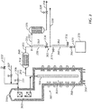
- a fired tubular furnace 1 is used for cracking hydrocarbons to ethylene and other olefinic compounds.
- the fired tubular furnace 1 has a convection section 2 and a cracking section 3.
- the furnace 1 contains one or more process tubes 4 through which hydrocarbons fed through a hydrocarbon feed line 6 are cracked to produce product gases upon the application of heat, with carbonaceous deposits referred to herein as coke produced as a by-product.
- Steam may additionally be fed as a diluent, such as via flow line 7.
- Heat is supplied by a heating medium introduced to the exterior of the process tubes 4 in the cracking section 3 of the furnace 1 through heating medium inlets 8, such as hearth burners, floor burners, or wall burners, and exiting through an exhaust 10.
- heating medium inlets 8 such as hearth burners, floor burners, or wall burners
- exhaust 10 exiting through an exhaust 10.
- the product gases flow through the product gas exit 12 and are then passed through one or more quench/heat exchangers 14 and 16, which are referred to herein as the primary transfer line exchanger 14 and the secondary transfer line exchanger 16.
- the product gases are then directed along line 18 to downstream processing equipment such as a quench tower and separation means (not shown).
- Valve 20 is positioned in the hydrocarbon feed line 6 to interrupt the hydrocarbon feed for decoking operations. After interruption of the hydrocarbon feed flow, steam and/or air from an air conduit 22 are injected to remove the coke buildup from process tubes 4.
- downstream valves 34, 36 control the direction of the effluent gas and coke spall away from the product separation system (not shown).
- the valve 34 to the downstream processing system (not shown) is also closed and a decoking effluent valve 36 is opened to direct the decoking effluent along an effluent line 38, such as to a decoking drum (not shown) or the firebox.
- the valve 34 to the processing system is closed and the effluent valve 36 is opened to direct the effluent away from the separation system upon interruption of the hydrocarbon feed flow and introduction of air into the steam matrix for decoking.
- the system includes a "coke catcher" 50 to minimize secondary transfer line exchanger plugging and coke contamination of the quench water system or firebox (not shown).
- the coke catcher 50 is located upstream of the secondary transfer line exchanger 16, where a change of direction of the effluent from the primary transfer line exchanger 14 causes the coke to continue straight into the coke catcher 50 while the effluent gas turns toward the secondary transfer line exchanger 16 via flow line 52.
- the coke catcher is essentially a length of pipe forming a "dead leg" in the heater outlet located after the primary transfer line exchanger 14 and before the secondary transfer line exchanger 16.
- the coke catcher is located in the plant such that the coke can periodically be emptied and carted away for disposal.
- the design as illustrated in Figure 2 provides no means for isolating the coke catcher from the heater effluent, thus requiring the heater 1 to be taken out of service and cooled to clean out the coke catcher 50. Shutting down cold stresses heater parts and causes a loss in production. Additionally, sizing the coke catcher for an extended run length may require a very large volume, and leaving coke and potentially some tar in the coke catcher for such an extended period may result in an agglomerate that is difficult to remove.
- US Patent 4,348,364 relates to a separation system and process to obtain a primary separation of particulate solids from a mixed phase gas-solid stream in a thermal regenerative cracking apparatus and process.
- DE 32 17 146 A1 describes a device for dedusting circulating gas of a coke dry cooling plant.
- the present disclosure provides for processes including a coke catcher that may be emptied during normal operation or steam standby, thereby overcoming the deficiencies in the prior design as discussed above, the coke catchers and process flows disclosed herein protecting the secondary transfer line exchanger from foulant while not limiting the time between heater cold shutdowns.
- the designs consider the impact of decoking options, such as when decoking to a firebox as opposed to a decoking drum. Further, flow and cost considerations are addressed in various embodiments; for example, decoke valves are fairly expensive, and process flows disclosed herein may provide for relocation of the decoke valve to facilitate coke catcher operations while not adding an expensive valve to the overall operating flow scheme.
- embodiments disclosed herein relate to a process for producing olefins as defined by claim 1.
- embodiments disclosed herein relate to a system for producing olefins as defined by claim 3.
- Embodiments disclosed herein relate to systems and processes for cracking ethane and propane to produce ethylene and propylene, as well as the efficient maintenance of these systems during normal cracking operations and during periodic decoking of the system.
- fouling of heat exchangers is a common problem within the petrochemical industry. As noted above, upsets or intentional changes in cracking conditions during normal operation can result in cooling and contraction of radiant section tubes, breaking off of coke or spalling, and flow of the coke or spalling downstream, plugging the secondary transferline exchanger and or downstream process.
- Embodiments disclosed herein relate to a process for reducing heat exchanger fouling in continuous or semi-continuous processes. Additionally, embodiments disclosed herein may be useful for preventing fouling in other process equipment, such as pumps, valves, compressors, and other common equipment where unwanted buildup of foulants is undesirable or where the presence of solid components is unwanted. Finally, minimizing the amount of large coke particles that enter the firebox in the case of firebox decoking help to facilitate the complete burning of coke and reduce the heater stack emissions.
- the foulant collection device may be isolated and emptied without discontinuing one or more portions of the continuous or semi-continuous process. In this manner, the foulant fraction does not get transported to the second heat exchange device.
- the accumulated foulant may be emptied from the collection device on a periodic basis without the need to shut down process critical process operations, providing for continuity of operations or improved process aspects, such as reduced stresses, ease of restart, increased production, and other benefits as may be highlighted from the following embodiments related to hydrocarbon cracking processes.
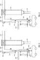
- a fired tubular furnace 301 is used for cracking hydrocarbons to ethylene and other olefinic compounds.
- the fired tubular furnace 301 has a convection section 302 and a cracking section 303.
- the furnace 301 contains one or more process tubes 304 through which hydrocarbons fed via hydrocarbon feed line 306, such as butane, propane and/or ethane, are cracked to produce product gases, such as ethylene and propylene, upon the application of heat.
- hydrocarbons such as C5, C6 and heavier hydrocarbons may also be used to produce olefins according to other embodiments.
- carbonaceous foulants such as coke and tars may be produced as a by-product.
- Steam may additionally be fed as a diluent, such as via flow line 307.
- Heat is supplied by a heating medium introduced to the exterior of the process tubes 304 in the cracking section 303 of the furnace 301 through heating medium inlets 308, such as hearth burners, floor burners, or wall burners, and exiting through an exhaust 310.
- the product gases flow through the product gas exit 312 and are then passed through one or more transfer line exchangers 314 and 316, which are referred to herein as the primary transfer line exchanger (PTLE 314) and the secondary transfer line exchanger (STLE 316).
- the product gases are then directed along line 318 to downstream processing equipment such as a quench tower and separation means (not shown).
- Valve 320 is positioned in the hydrocarbon feed line 306 to interrupt the hydrocarbon feed for decoking operations. After interruption of the hydrocarbon feed flow, steam and/or air from an air conduit 322 are injected to remove the coke buildup from process tubes 304.
- downstream valves 334, 336 control the direction of the effluent gas and coke spall away from the product separation system (not shown).
- the valve 334 to the downstream processing system (not shown) is also closed and a decoking effluent valve 336 is opened to direct the decoking effluent along an effluent line 338, such as to a decoking drum (not shown) or the firebox (such as via heating medium inlets 308 or an alternate combustion device).
- valve 334 to the processing system is closed and the effluent valve 336 is opened to direct the effluent away from the separation system upon interruption of the hydrocarbon feed flow and introduction of air into the steam matrix for decoking.
- transfer line 315 branches, with flow conduit 350 proceeding in the same general direction as flow in transfer line 315, and flow line 352 angling from transfer line 315.
- the general direction of flow conduits 350, 352 are such that the momentum of the stream carries the coke/foulants into conduit 350 while the product gases flow through conduit 352 and into STLE 316 for further cooling and feed to downstream operations (not shown).
- valve 336 is normally closed.
- a first portion 354 of the coke catcher or dead leg may be considered as the volume of flow conduit 350 between branch point 355 and valve 336.
- This portion of the coke catcher may be sized to temporarily accumulate foulant carried into the coke catcher.
- the volume of the first portion 354 may be sized to collect an amount of coke/foulant produced during a single cracking cycle or a portion thereof. In other embodiments, the first portion may be sized for more than one cracking cycle, so as to accommodate for periods when coke make may be greater than expected or greater than during typical operations.
- Dead leg portion 354 will be emptied into the remaining volume of the coke catcher via cycling of valve 336 during high steam standby prior to decoking.
- the accumulated foulant then passes through valve 336 into flow conduit 360.
- flow conduit 350 branches, with flow conduit 360 proceeding in the same general direction as flow in transfer line 350, and flow line 338 angling from transfer line 350.
- the general direction of flow conduits 360 and 338 are such that the momentum of the stream carries the accumulated foulants and any solid components in the effluent during decoking into conduit 360 while the vaporous components of the decoking effluent recovered from PTLE 314 change direction and flow through conduit 338 to downstream operations (not shown), such as a decoking drum or a firebox.
- a second portion 364 of the coke catcher or dead leg may be considered as the volume of flow conduit 352 between branch point 365 and valve 366.
- This portion of the coke catcher may be sized to temporarily accumulate coke/foulant carried into the coke catcher, such as that produced over a single cracking and decoking cycle, or over multiple cracking and decoking cycles.
- the sizing of portions 354 and 364 should be such that coke/foulant is not carried into stream 338 or to the downstream operations, such as the aforementioned decoking drum or firebox.
- the terminal portion 370 of the coke catcher may be located in the plant such that the accumulated coke/foulant can periodically be emptied and carted away for disposal.
- the bin 379, vessel, hopper, or structure into which the accumulated foulant is emptied may be movable, such as via wheels or forklift, and may be continuously located proximate the terminal portion 370, or may be temporarily placed for emptying when desired or necessary.
- Coke catchers may also include other valves, bulkheads, handholes, or other functional connections.
- valve 372 may be provided as a steam supply inlet for purging any lighter hydrocarbons from the accumulated coke/foulant prior to discharge.
- valve 374 may be provided as a cooling water inlet to quench the accumulated foulant and provide a liquid environment to prevent exposure of potentially pyrophoric material to air.
- Other inlets and outlets may also be provided for nitrogen purge or sweep, cleaning, or other purposes. If desired or beneficial, one or more of the connections may be attached to the coke catcher using an angled connection to prevent buildup of foulant.
- FIG. 4 a simplified process flow diagram of one embodiment of a process for reducing heat exchanger fouling or stack emissions during production of olefins is illustrated, where like numerals represent like parts.
- the effluent line 315 from the PTLE 314 traverses horizontally.
- the vapor phase effluent changes direction into branch line 352 and flows to the upper head of STLE 316.
- the momentum of the stream carries the foulant forward into branch line 350, effectively separating the foulant from the vapors and protecting STLE 316 from potential plugging.
- a turn 380 may be provided to direct the foulant into portion 354 for accumulation during the operating cycle(s).
- turn 380 may be provided by use of a piping elbow, tee, or similar connections.
- turn 380 may be an elbow having an erosion barrier 382.
- turn 380 may be provided by use of a tee, one leg of which may be filled with coke particles, a solid metal pad or other suitable materials to form erosion barrier 382.
- the erosion barrier 382 may be integral with the remainder of the tee, or may be a removable plug or pad, so that the erosion barrier may be routinely replaced or repaired without the need to disassemble the entirety of turn 380.
- Figure 4 also includes a drain line 390, provided to remove water or other liquids that may settle in the coke catcher during normal operations, steam purging, or water cooling.
- bin 379 may be any type of collection device, including open-type structures not requiring an air tight seal. This assumes that line 338 is feeding to a decoke drum, not a firebox.
- a decoke valve 336 may provide for positive isolation from the process streams, assuming no other heater is being decoked to the same decoke drum when the bottom valve 366 is opened to empty the foulant.
- FIG. 5 a simplified process flow diagram of one embodiment of a process for reducing heat exchanger fouling during production of olefins is illustrated, where like numerals represent like parts.
- collection bin 379 is connected to valve 366 using a flexible type connection 392 or other connection means so as to provide an overall sealed system.
- the sealed system of Figure 5 may provide greater protection against exposure to coke, benzene, or other chemical species.
- the bin 379 is vented via flow line 338 to the decoke drum or the firebox.
- the embodiment illustrated in Figure 5 may also be preferred when decoking to a firebox, as there is potential for the pressure in the firebox to exceed the downstream pressures, which may result in hot flue gases being pushed back through the decoke line.
- the decoke line 338 is incorporated into the coke catcher.
- the volume of the piping in the coke catcher below the decoke line 338 should be significant enough to provide for accumulation of coke/foulant without blocking the decoke line 338 itself.
- the time periods between emptying of the coke catcher necessarily depends upon the volume provided as well as the typical coke make during operations. A large volume or routine emptying may prevent blockage of the decoke line 338.
- a level measurement device may be provided such that the coke catcher may be routinely emptied before the accumulated level reaches the decoke line 338.
- the STLE is not decoked. While some buildup in the STLE may be removed during decoking as shown in the process of Figure 1 , it is anticipated that, using coke catchers according to embodiments illustrated in Figures 3-5 and disclosed herein, buildup in the STLE during normal operations may be significantly decreased, meaning that only periodic maintenance of the STLE may be needed, and which is routinely performed otherwise, even for the processes of Figure 1 (e.g., no additional maintenance costs are anticipated when the decoke line is moved upstream of the STLE). As another difference, the STLE has flow on only one side during decoke operations.
- FIG. 6 a simplified process flow diagram of a process for reducing heat exchanger fouling during production of olefins is illustrated, where like numerals represent like parts.
- the decoke line 338 and decoke valve 336 are located downstream of STLE 316, such as to prevent the efficiency losses and stresses noted above.
- the coke catcher is isolatable from the heater via valve 400, which may be a decoke type valve similar to the valve 336 used in the embodiments of Figures 3-5 , so as to isolate the bottom portion 364 during emptying of the coke catcher. While this system may advantageously maintain heat recover efficiencies, it requires additional decoke valve(s), adding to the capital and maintenance costs of the overall system.
- the decoke line provides for venting of vapor during emptying of the coke catcher into bin 379.
- a small vent line 410 may be provided between bin 379 and the decoke line to provide for venting during emptying of the coke catcher.
- embodiments disclosed herein may provide for processes including a coke catcher that may be emptied during normal operation or steam standby.
- the coke catchers and process flows disclosed herein may protect the secondary transfer line exchangers from foulant while not limiting the time between heater cold shutdowns.
- the designs consider the impact of decoking options, such as when decoking to a firebox as opposed to a decoking drum. Further, flow and cost considerations are addressed in various embodiments; for example, decoke valves are fairly expensive, and process flows disclosed herein may provide for relocation of the decoke valve to facilitate coke catcher operations while not adding an expensive valve to the overall operating flow scheme. Additionally, embodiments disclosed herein may provide for reduced emissions by excluding a large portion of the coke from the firebox during firebox decoking.
Landscapes
- Chemical & Material Sciences (AREA)
- Oil, Petroleum & Natural Gas (AREA)
- Chemical Kinetics & Catalysis (AREA)
- Engineering & Computer Science (AREA)
- General Chemical & Material Sciences (AREA)
- Organic Chemistry (AREA)
- Physics & Mathematics (AREA)
- Thermal Sciences (AREA)
- Production Of Liquid Hydrocarbon Mixture For Refining Petroleum (AREA)
- Coke Industry (AREA)
Claims (4)
- Verfahren zur Herstellung von Olefinen, wobei das Verfahren umfasst:Leiten eines Kohlenwasserstoff-Zustroms und gegebenenfalls Dampf während eines Cracking-Zyklus durch ein Wärmetauscherrohr in einer Wärmestrahlungskammer eines Heizgeräts unter solchen Bedingungen, dass wenigstens ein Teil des Kohlenwasserstoffs gecrackt wird, wobei ein Abfluss entsteht, der Olefine und Nebenprodukte einschließlich schwererer Kohlenwasserstoffe und Koks umfasst;Leiten von wenigstens einem aus Stickstoff, Dampf, Luft und Sauerstoff während eines Entkokungszyklus durch das Wärmetauscherrohr in der Wärmestrahlungskammer des Heizgeräts unter solchen Bedingungen, dass wenigstens ein Teil des Wärmetauscherrohrs entkokt wird, wobei ein Entkokungsabfluss entsteht;Kühlen des Abflusses oder des Entkokungsabflusses in einem primären Übertragungsleitungsaustauscher unter Bildung eines gekühlten Abflusses, der eine gasförmige Fraktion und eine belagbildende Fraktion umfasst;Übertragen des gekühlten Abflusses durch eine Strömungsleitung in einen sekundären Übertragungsleitungsaustauscher, wobei sich die Strömungsleitung verzweigt und dabei Folgendes bewirkt: (i) dass der Strom der gasförmigen Fraktion wenigstens während des Cracking-Zyklus seine Richtung ändert, bevor er in den sekundären Übertragungsleitungsaustauscher eintritt, und (ii) dass der Strom der belagbildenden Fraktion in einen Koksfänger weiterläuft;Akkumulieren einer Menge der belagbildenden Fraktion in dem Koksfänger oder einem ersten Teil davon; undAusleeren von akkumulierter belagbildender Fraktion aus dem Koksfänger oder einem zweiten Teil davon, ohne das Heizgerät herunterzufahren;wobei der Akkumulationsschritt das Akkumulieren einer Menge der belagbildenden Fraktion in einem ersten Teil (354) des Koksfängers umfasst, wobei das Verfahren weiterhin umfasst:Transportieren des akkumulierten Belagbildners in einen zweiten Teil (364) der Belagbildnersammelvorrichtung;Isolieren des ersten Teils (354) des Koksfängers gegenüber dem zweiten Teil (364) des Koksfängers vor dem Entleerungsschritt;wobei das Transportieren des akkumulierten Belagbildners aus dem ersten Teil (354) in den zweiten Teil (364) eingeleitet wird, wenn das Verfahren aus dem Verkokungszyklus in den Entkokungszyklus übergeht; undwobei während des Entkokungszyklus der Entkokungsabfluss wenigstens durch den ersten Teil (354) des Koksfängers tritt.
- Verfahren gemäß Anspruch 1, weiterhin umfassend das In-Kontakt-Bringen des akkumulierten Belagbildners in dem zweiten Teil (364) des Koksfängers mit wenigstens einem aus Dampf, Wasser und Stickstoff vor dem Entleerungsschritt.
- System zur Herstellung von Olefinen, wobei das System umfasst:ein Heizgerät;ein oder mehrere Wärmetauscherrohre zum:a) Leiten eines Kohlenwasserstoff-Zustroms und gegebenenfalls Dampf während eines Cracking-Zyklus durch eine Wärmestrahlungskammer des Heizgeräts unter solchen Bedingungen, dass wenigstens ein Teil des Kohlenwasserstoffs gecrackt wird, wobei ein Abfluss entsteht, der Olefine und Nebenprodukte einschließlich schwererer Kohlenwasserstoffe und Koks umfasst; undb) Leiten von wenigstens einem aus Stickstoff, Dampf, Luft und Sauerstoff während eines Entkokungszyklus durch die Wärmestrahlungskammer des Heizgeräts unter solchen Bedingungen, dass wenigstens ein Teil des Wärmetauscherrohrs entkokt wird, wobei ein Entkokungsabfluss entsteht;einen primären Übertragungsleitungsaustauscher zum Kühlen des Abflusses oder des Entkokungsabflusses unter Bildung eines gekühlten Abflusses, der eine gasförmige Fraktion und eine belagbildende Fraktion umfasst;eine Strömungsleitung zum Übertragen des gekühlten Abflusses in einen sekundären Übertragungsleitungsaustauscher;eine Verzweigung in der Strömungsleitung, wobei die Verzweigung Folgendes bewirkt: (i) dass der Strom der gasförmigen Fraktion wenigstens während des Cracking-Zyklus seine Richtung ändert, bevor er in den sekundären Übertragungsleitungsaustauscher eintritt, und (ii) dass der Strom der belagbildenden Fraktion in einen Koksfänger weiterläuft;den Koksfänger, wobei der Koksfänger einen oder mehrere Teile (354, 364) mit einem Volumen zum Akkumulieren einer Menge der belagbildenden Fraktion aufweist; undEinrichtungen zum Ausleeren von akkumulierter belagbildender Fraktion, die so konfiguriert sind, dass sie akkumulierte belagbildende Fraktion aus dem Koksfänger oder einem Teil davon ausleeren können, ohne das Heizgerät herunterzufahren;wobei der Koksfänger umfasst:einen ersten Teil (354) mit einem Volumen zum Akkumulieren einer Menge der belagbildenden Fraktion;einen zweiten Teil (364) zum Aufnehmen von akkumuliertem Belagbildner aus dem ersten Teil (354); undein Ventil (336) zum Isolieren des ersten Teils (354) gegenüber dem zweiten Teil (364), um das Isolieren und Entleeren von akkumuliertem Belagbildner aus dem zweiten Teil (364) zu ermöglichen, ohne das Heizgerät herunterzufahren;wobei das System so konfiguriert ist, dass es das Ventil (336) zum Isolieren öffnet, um für den Transport des akkumulierten Belagbildners aus dem ersten Teil (354) in den zweiten Teil (364) zu sorgen, wenn es aus dem Verkokungszyklus in den Entkokungszyklus übergeht; undwobei das System weiterhin eine Entkokungsströmungsleitung (338) umfasst, die sich hinter dem Ventil (336) zum Isolieren befindet und so konfiguriert ist, dass sie das Strömen des Entkokungsabflusses aus dem primären Übertragungsleitungsaustauscher durch den ersten Teil (354) des Koksfängers in die Entkokungsströmungsleitung (338) ermöglicht.
- System gemäß Anspruch 3, weiterhin umfassend Strömungsleitungen zum In-Kontakt-Bringen des akkumulierten Belagbildners in dem zweiten Teil (364) des Koksfängers mit wenigstens einem aus Dampf, Wasser und Stickstoff.
Priority Applications (1)
| Application Number | Priority Date | Filing Date | Title |
|---|---|---|---|
| PL13819522T PL2875101T3 (pl) | 2012-07-20 | 2013-07-11 | Wychwytywacz koksu |
Applications Claiming Priority (2)
| Application Number | Priority Date | Filing Date | Title |
|---|---|---|---|
| US13/554,460 US8647415B1 (en) | 2012-07-20 | 2012-07-20 | Coke catcher |
| PCT/US2013/050013 WO2014014731A1 (en) | 2012-07-20 | 2013-07-11 | Coke catcher |
Publications (3)
| Publication Number | Publication Date |
|---|---|
| EP2875101A1 EP2875101A1 (de) | 2015-05-27 |
| EP2875101A4 EP2875101A4 (de) | 2016-04-06 |
| EP2875101B1 true EP2875101B1 (de) | 2019-09-04 |
Family
ID=49947104
Family Applications (1)
| Application Number | Title | Priority Date | Filing Date |
|---|---|---|---|
| EP13819522.7A Active EP2875101B1 (de) | 2012-07-20 | 2013-07-11 | Koksfänger |
Country Status (19)
| Country | Link |
|---|---|
| US (1) | US8647415B1 (de) |
| EP (1) | EP2875101B1 (de) |
| JP (2) | JP6180525B2 (de) |
| KR (1) | KR101766099B1 (de) |
| CN (1) | CN104583370B (de) |
| AR (1) | AR092030A1 (de) |
| BR (1) | BR112015001222B1 (de) |
| CA (1) | CA2879613C (de) |
| CL (1) | CL2015000127A1 (de) |
| ES (1) | ES2759876T3 (de) |
| IN (1) | IN2015MN00115A (de) |
| MX (1) | MX375280B (de) |
| MY (1) | MY169985A (de) |
| PH (1) | PH12015500117B1 (de) |
| PL (1) | PL2875101T3 (de) |
| SG (1) | SG11201500400WA (de) |
| TW (1) | TWI530558B (de) |
| WO (1) | WO2014014731A1 (de) |
| ZA (1) | ZA201500545B (de) |
Families Citing this family (27)
| Publication number | Priority date | Publication date | Assignee | Title |
|---|---|---|---|---|
| AU2016368277B2 (en) | 2015-12-07 | 2022-04-07 | Bl Technologies, Inc. | System and method to mitigate fouling during a hydrocarbon refining process |
| US10870803B2 (en) * | 2016-07-16 | 2020-12-22 | Ramin Karimzadeh | Method for upgrading a hydrocarbon feed |
| CA2946264C (en) * | 2016-10-25 | 2026-04-07 | Nova Chemicals Corporation | Use of semipermeable membranes in cracking coils |
| US10696906B2 (en) | 2017-09-29 | 2020-06-30 | Marathon Petroleum Company Lp | Tower bottoms coke catching device |
| US12000720B2 (en) | 2018-09-10 | 2024-06-04 | Marathon Petroleum Company Lp | Product inventory monitoring |
| CA3033604C (en) * | 2019-02-12 | 2022-12-13 | Michael KOSELEK | Decoking process |
| US12031676B2 (en) | 2019-03-25 | 2024-07-09 | Marathon Petroleum Company Lp | Insulation securement system and associated methods |
| US11975316B2 (en) | 2019-05-09 | 2024-05-07 | Marathon Petroleum Company Lp | Methods and reforming systems for re-dispersing platinum on reforming catalyst |
| CA3212048A1 (en) | 2019-05-30 | 2020-11-30 | Marathon Petroleum Company Lp | Methods and systems for minimizing nox and co emissions in natural draft heaters |
| US12024684B2 (en) | 2019-07-24 | 2024-07-02 | Exxonmobil Chemical Patents Inc. | Furnace systems and methods for cracking hydrocarbons |
| CN112538365B (zh) * | 2019-09-23 | 2022-11-01 | 中国石化工程建设有限公司 | 一种乙烯裂解炉裂解气管线清焦系统及裂解气管线防焦与除焦的方法 |
| EP3839011A1 (de) | 2019-12-19 | 2021-06-23 | Linde GmbH | Verfahren und anlage zur herstellung von kohlenwasserstoffen |
| US11384301B2 (en) | 2020-02-19 | 2022-07-12 | Marathon Petroleum Company Lp | Low sulfur fuel oil blends for stability enhancement and associated methods |
| US12461022B2 (en) | 2021-02-25 | 2025-11-04 | Marathon Petroleum Company Lp | Methods and assemblies for determining and using standardized spectral responses for calibration of spectroscopic analyzers |
| US11702600B2 (en) | 2021-02-25 | 2023-07-18 | Marathon Petroleum Company Lp | Assemblies and methods for enhancing fluid catalytic cracking (FCC) processes during the FCC process using spectroscopic analyzers |
| US11905468B2 (en) | 2021-02-25 | 2024-02-20 | Marathon Petroleum Company Lp | Assemblies and methods for enhancing control of fluid catalytic cracking (FCC) processes using spectroscopic analyzers |
| US20250012744A1 (en) | 2021-02-25 | 2025-01-09 | Marathon Petroleum Company Lp | Methods and assemblies for enhancing control of refining processes using spectroscopic analyzers |
| US11898109B2 (en) | 2021-02-25 | 2024-02-13 | Marathon Petroleum Company Lp | Assemblies and methods for enhancing control of hydrotreating and fluid catalytic cracking (FCC) processes using spectroscopic analyzers |
| US12473500B2 (en) | 2021-02-25 | 2025-11-18 | Marathon Petroleum Company Lp | Assemblies and methods for enhancing control of fluid catalytic cracking (FCC) processes using spectroscopic analyzers |
| EP4059916A1 (de) | 2021-03-15 | 2022-09-21 | Linde GmbH | Verfahren und anlage zur erzeugung eines produktkohlenwasserstoffs |
| US11692141B2 (en) | 2021-10-10 | 2023-07-04 | Marathon Petroleum Company Lp | Methods and systems for enhancing processing of hydrocarbons in a fluid catalytic cracking unit using a renewable additive |
| CA3188122A1 (en) | 2022-01-31 | 2023-07-31 | Marathon Petroleum Company Lp | Systems and methods for reducing rendered fats pour point |
| US12311305B2 (en) | 2022-12-08 | 2025-05-27 | Marathon Petroleum Company Lp | Removable flue gas strainer and associated methods |
| US12306076B2 (en) | 2023-05-12 | 2025-05-20 | Marathon Petroleum Company Lp | Systems, apparatuses, and methods for sample cylinder inspection, pressurization, and sample disposal |
| US12533615B2 (en) | 2023-06-02 | 2026-01-27 | Marathon Petroleum Company Lp | Methods and systems for reducing contaminants in a feed stream |
| US12415962B2 (en) | 2023-11-10 | 2025-09-16 | Marathon Petroleum Company Lp | Systems and methods for producing aviation fuel |
| US12599848B2 (en) | 2024-06-03 | 2026-04-14 | Marathon Petroleum Company Lp | Systems, analyzers, controllers, and associated methods to enhance fluid separation for distillation operations |
Family Cites Families (22)
| Publication number | Priority date | Publication date | Assignee | Title |
|---|---|---|---|---|
| JPS5318062A (en) * | 1976-08-02 | 1978-02-18 | Babcock Hitachi Kk | Baffle plate |
| US4176045A (en) * | 1978-07-10 | 1979-11-27 | Pullman Incorporated | Pyrolysis coke inhibition |
| US4348364A (en) | 1979-07-06 | 1982-09-07 | Stone & Webster Engineering Corp. | Thermal regenerative cracking apparatus and separation system therefor |
| US5045176A (en) * | 1981-05-13 | 1991-09-03 | Ashland Oil, Inc. | Carbometallic oil conversion with ballistic separation |
| JPS58132081A (ja) * | 1982-01-08 | 1983-08-06 | Idemitsu Petrochem Co Ltd | 炭化水素の熱分解方法 |
| DE3217146A1 (de) * | 1982-05-07 | 1983-11-10 | Krupp-Koppers Gmbh, 4300 Essen | Vorrichtung zur entstaubung von kreislaufgas einer kokstrockenkuehlanlage |
| JPS61274720A (ja) * | 1985-05-31 | 1986-12-04 | Asahi Glass Co Ltd | 慣性型集塵器 |
| JPH02108716U (de) * | 1989-02-10 | 1990-08-29 | ||
| ATE114705T1 (de) * | 1989-04-14 | 1994-12-15 | Procedes Petroliers Petrochim | Verfahren und apparat zur entkoksung von dampfkrackanlagen. |
| FR2652817B1 (fr) * | 1989-10-06 | 1993-11-26 | Procedes Petroliers Petrochimiqu | Procede et installation de vapocraquage d'hydrocarbures, a recyclage de particules solides erosives. |
| JPH0478253U (de) * | 1990-11-19 | 1992-07-08 | ||
| DE4405884C1 (de) | 1994-02-21 | 1995-09-07 | Mannesmann Ag | Wärmeaustauschfläche in Reaktoren und/oder Wärmeaustauschern und Verfahren zur Herstellung einer katalytisch desaktivierten Metalloberfläche |
| JP2777061B2 (ja) * | 1994-07-12 | 1998-07-16 | 九州電力株式会社 | 固体粒子による蒸気タービン翼の侵食損傷防止装置 |
| JPH11324616A (ja) * | 1998-05-14 | 1999-11-26 | Kyushu Electric Power Co Inc | 蒸気タービンへのボイラスケール捕集装置 |
| JP3095734B2 (ja) * | 1999-03-09 | 2000-10-10 | 九州電力株式会社 | ボイラ蒸気管のスケール捕集装置 |
| EP2650346A1 (de) | 2004-04-28 | 2013-10-16 | Headwaters Heavy Oil, LLC | Verfahren zur Schwerölhydrierung in einem Wirbelschichtreaktor |
| US7244871B2 (en) | 2004-05-21 | 2007-07-17 | Exxonmobil Chemical Patents, Inc. | Process and apparatus for removing coke formed during steam cracking of hydrocarbon feedstocks containing resids |
| US7914668B2 (en) * | 2005-11-14 | 2011-03-29 | Exxonmobil Research & Engineering Company | Continuous coking process |
| JP2007198635A (ja) * | 2006-01-24 | 2007-08-09 | Kawasaki Heavy Ind Ltd | シャフト式廃棄物溶融炉およびその運転方法 |
| JP2008215098A (ja) * | 2007-02-28 | 2008-09-18 | Mitsubishi Heavy Ind Ltd | ボイラ蒸気管のスケール捕集装置 |
| US20090114567A1 (en) | 2007-11-07 | 2009-05-07 | Maxwell James F | Cracking hydrocarbonaceous materials with heating bodies |
| CN101265414B (zh) * | 2008-04-08 | 2011-06-29 | 中国石油兰州石油化工公司 | 油溶性清焦剂及其制备 |
-
2012
- 2012-07-20 US US13/554,460 patent/US8647415B1/en active Active
-
2013
- 2013-07-11 CN CN201380041358.2A patent/CN104583370B/zh active Active
- 2013-07-11 KR KR1020157004322A patent/KR101766099B1/ko active Active
- 2013-07-11 SG SG11201500400WA patent/SG11201500400WA/en unknown
- 2013-07-11 IN IN115MUN2015 patent/IN2015MN00115A/en unknown
- 2013-07-11 JP JP2015523133A patent/JP6180525B2/ja not_active Expired - Fee Related
- 2013-07-11 ES ES13819522T patent/ES2759876T3/es active Active
- 2013-07-11 EP EP13819522.7A patent/EP2875101B1/de active Active
- 2013-07-11 CA CA2879613A patent/CA2879613C/en active Active
- 2013-07-11 PL PL13819522T patent/PL2875101T3/pl unknown
- 2013-07-11 MY MYPI2015000132A patent/MY169985A/en unknown
- 2013-07-11 BR BR112015001222-1A patent/BR112015001222B1/pt active IP Right Grant
- 2013-07-11 MX MX2015000805A patent/MX375280B/es active IP Right Grant
- 2013-07-11 WO PCT/US2013/050013 patent/WO2014014731A1/en not_active Ceased
- 2013-07-12 AR ARP130102501A patent/AR092030A1/es active IP Right Grant
- 2013-07-19 TW TW102125903A patent/TWI530558B/zh active
-
2015
- 2015-01-19 CL CL2015000127A patent/CL2015000127A1/es unknown
- 2015-01-20 PH PH12015500117A patent/PH12015500117B1/en unknown
- 2015-01-23 ZA ZA2015/00545A patent/ZA201500545B/en unknown
-
2016
- 2016-11-18 JP JP2016224723A patent/JP2017095704A/ja not_active Withdrawn
Non-Patent Citations (1)
| Title |
|---|
| None * |
Also Published As
| Publication number | Publication date |
|---|---|
| KR20150040936A (ko) | 2015-04-15 |
| JP2015522695A (ja) | 2015-08-06 |
| BR112015001222A2 (pt) | 2017-07-04 |
| IN2015MN00115A (de) | 2015-10-16 |
| TWI530558B (zh) | 2016-04-21 |
| SG11201500400WA (en) | 2015-02-27 |
| PL2875101T3 (pl) | 2020-05-18 |
| US20140024873A1 (en) | 2014-01-23 |
| ES2759876T3 (es) | 2020-05-12 |
| EP2875101A4 (de) | 2016-04-06 |
| JP2017095704A (ja) | 2017-06-01 |
| EP2875101A1 (de) | 2015-05-27 |
| AR092030A1 (es) | 2015-03-18 |
| PH12015500117A1 (en) | 2015-03-30 |
| US8647415B1 (en) | 2014-02-11 |
| CA2879613A1 (en) | 2014-01-23 |
| CA2879613C (en) | 2017-03-14 |
| MX2015000805A (es) | 2015-09-07 |
| KR101766099B1 (ko) | 2017-08-07 |
| MY169985A (en) | 2019-06-19 |
| ZA201500545B (en) | 2016-01-27 |
| WO2014014731A1 (en) | 2014-01-23 |
| CL2015000127A1 (es) | 2015-05-22 |
| BR112015001222B1 (pt) | 2020-12-22 |
| PH12015500117B1 (en) | 2015-03-30 |
| CN104583370A (zh) | 2015-04-29 |
| CN104583370B (zh) | 2017-09-19 |
| JP6180525B2 (ja) | 2017-08-16 |
| TW201412970A (zh) | 2014-04-01 |
| MX375280B (es) | 2025-03-06 |
Similar Documents
| Publication | Publication Date | Title |
|---|---|---|
| EP2875101B1 (de) | Koksfänger | |
| US12024684B2 (en) | Furnace systems and methods for cracking hydrocarbons | |
| EP2310472B1 (de) | Verfahren zum prozessbegleitenden entkoken eines ofens zum cracken eines kohlenwasserstoff-einsatzstoffs | |
| US9644149B2 (en) | Medium pressure steam intervention in an olefin cracking furnace decoke procedure | |
| KR100966962B1 (ko) | 탄화수소 열분해 유출물을 처리하는 방법 | |
| CN106661461B (zh) | 用于烃蒸汽裂解炉除焦的方法和设备 | |
| JP4777423B2 (ja) | 炭化水素パイロリシス排出物の処理法 | |
| RU2491321C2 (ru) | Способ и устройство для предварительного нагрева сырья с помощью охладителя отходящих газов | |
| US12473497B2 (en) | Processes and systems for removing coke particles from a pyrolysis effluent | |
| RU2463334C1 (ru) | Установка термодеструкции для переработки нефтяных остатков | |
| AU2023369794A1 (en) | Method for production of synthesis gas and a reactor | |
| KR100746583B1 (ko) | 코크 저감용 탄화수소 열분해 반응장치 및 코크의 저감방법 | |
| CN117561318A (zh) | 包括流化催化裂化反应器和再生器的热集成方法 | |
| JPS6332118B2 (de) | ||
| EA043956B1 (ru) | Объединенный термический и каталитический крекинг для получения олефинов |
Legal Events
| Date | Code | Title | Description |
|---|---|---|---|
| PUAI | Public reference made under article 153(3) epc to a published international application that has entered the european phase |
Free format text: ORIGINAL CODE: 0009012 |
|
| 17P | Request for examination filed |
Effective date: 20150216 |
|
| AK | Designated contracting states |
Kind code of ref document: A1 Designated state(s): AL AT BE BG CH CY CZ DE DK EE ES FI FR GB GR HR HU IE IS IT LI LT LU LV MC MK MT NL NO PL PT RO RS SE SI SK SM TR |
|
| AX | Request for extension of the european patent |
Extension state: BA ME |
|
| DAX | Request for extension of the european patent (deleted) | ||
| RA4 | Supplementary search report drawn up and despatched (corrected) |
Effective date: 20160308 |
|
| RIC1 | Information provided on ipc code assigned before grant |
Ipc: C10G 75/00 20060101ALI20160302BHEP Ipc: C10G 9/16 20060101AFI20160302BHEP |
|
| STAA | Information on the status of an ep patent application or granted ep patent |
Free format text: STATUS: EXAMINATION IS IN PROGRESS |
|
| 17Q | First examination report despatched |
Effective date: 20170804 |
|
| GRAP | Despatch of communication of intention to grant a patent |
Free format text: ORIGINAL CODE: EPIDOSNIGR1 |
|
| STAA | Information on the status of an ep patent application or granted ep patent |
Free format text: STATUS: GRANT OF PATENT IS INTENDED |
|
| INTG | Intention to grant announced |
Effective date: 20190201 |
|
| RAP1 | Party data changed (applicant data changed or rights of an application transferred) |
Owner name: LUMMUS TECHNOLOGY LLC |
|
| GRAJ | Information related to disapproval of communication of intention to grant by the applicant or resumption of examination proceedings by the epo deleted |
Free format text: ORIGINAL CODE: EPIDOSDIGR1 |
|
| STAA | Information on the status of an ep patent application or granted ep patent |
Free format text: STATUS: EXAMINATION IS IN PROGRESS |
|
| STAA | Information on the status of an ep patent application or granted ep patent |
Free format text: STATUS: GRANT OF PATENT IS INTENDED |
|
| GRAS | Grant fee paid |
Free format text: ORIGINAL CODE: EPIDOSNIGR3 |
|
| INTC | Intention to grant announced (deleted) | ||
| GRAA | (expected) grant |
Free format text: ORIGINAL CODE: 0009210 |
|
| STAA | Information on the status of an ep patent application or granted ep patent |
Free format text: STATUS: THE PATENT HAS BEEN GRANTED |
|
| AK | Designated contracting states |
Kind code of ref document: B1 Designated state(s): AL AT BE BG CH CY CZ DE DK EE ES FI FR GB GR HR HU IE IS IT LI LT LU LV MC MK MT NL NO PL PT RO RS SE SI SK SM TR |
|
| REG | Reference to a national code |
Ref country code: GB Ref legal event code: FG4D |
|
| REG | Reference to a national code |
Ref country code: CH Ref legal event code: EP |
|
| REG | Reference to a national code |
Ref country code: AT Ref legal event code: REF Ref document number: 1175337 Country of ref document: AT Kind code of ref document: T Effective date: 20190915 |
|
| REG | Reference to a national code |
Ref country code: DE Ref legal event code: R096 Ref document number: 602013060132 Country of ref document: DE |
|
| REG | Reference to a national code |
Ref country code: IE Ref legal event code: FG4D |
|
| REG | Reference to a national code |
Ref country code: SE Ref legal event code: TRGR |
|
| REG | Reference to a national code |
Ref country code: NL Ref legal event code: FP |
|
| REG | Reference to a national code |
Ref country code: LT Ref legal event code: MG4D |
|
| PG25 | Lapsed in a contracting state [announced via postgrant information from national office to epo] |
Ref country code: BG Free format text: LAPSE BECAUSE OF FAILURE TO SUBMIT A TRANSLATION OF THE DESCRIPTION OR TO PAY THE FEE WITHIN THE PRESCRIBED TIME-LIMIT Effective date: 20191204 Ref country code: LT Free format text: LAPSE BECAUSE OF FAILURE TO SUBMIT A TRANSLATION OF THE DESCRIPTION OR TO PAY THE FEE WITHIN THE PRESCRIBED TIME-LIMIT Effective date: 20190904 Ref country code: HR Free format text: LAPSE BECAUSE OF FAILURE TO SUBMIT A TRANSLATION OF THE DESCRIPTION OR TO PAY THE FEE WITHIN THE PRESCRIBED TIME-LIMIT Effective date: 20190904 |
|
| REG | Reference to a national code |
Ref country code: NO Ref legal event code: T2 Effective date: 20190904 |
|
| PG25 | Lapsed in a contracting state [announced via postgrant information from national office to epo] |
Ref country code: RS Free format text: LAPSE BECAUSE OF FAILURE TO SUBMIT A TRANSLATION OF THE DESCRIPTION OR TO PAY THE FEE WITHIN THE PRESCRIBED TIME-LIMIT Effective date: 20190904 Ref country code: GR Free format text: LAPSE BECAUSE OF FAILURE TO SUBMIT A TRANSLATION OF THE DESCRIPTION OR TO PAY THE FEE WITHIN THE PRESCRIBED TIME-LIMIT Effective date: 20191205 Ref country code: LV Free format text: LAPSE BECAUSE OF FAILURE TO SUBMIT A TRANSLATION OF THE DESCRIPTION OR TO PAY THE FEE WITHIN THE PRESCRIBED TIME-LIMIT Effective date: 20190904 Ref country code: AL Free format text: LAPSE BECAUSE OF FAILURE TO SUBMIT A TRANSLATION OF THE DESCRIPTION OR TO PAY THE FEE WITHIN THE PRESCRIBED TIME-LIMIT Effective date: 20190904 |
|
| REG | Reference to a national code |
Ref country code: AT Ref legal event code: MK05 Ref document number: 1175337 Country of ref document: AT Kind code of ref document: T Effective date: 20190904 |
|
| PG25 | Lapsed in a contracting state [announced via postgrant information from national office to epo] |
Ref country code: RO Free format text: LAPSE BECAUSE OF FAILURE TO SUBMIT A TRANSLATION OF THE DESCRIPTION OR TO PAY THE FEE WITHIN THE PRESCRIBED TIME-LIMIT Effective date: 20190904 Ref country code: EE Free format text: LAPSE BECAUSE OF FAILURE TO SUBMIT A TRANSLATION OF THE DESCRIPTION OR TO PAY THE FEE WITHIN THE PRESCRIBED TIME-LIMIT Effective date: 20190904 Ref country code: AT Free format text: LAPSE BECAUSE OF FAILURE TO SUBMIT A TRANSLATION OF THE DESCRIPTION OR TO PAY THE FEE WITHIN THE PRESCRIBED TIME-LIMIT Effective date: 20190904 Ref country code: PT Free format text: LAPSE BECAUSE OF FAILURE TO SUBMIT A TRANSLATION OF THE DESCRIPTION OR TO PAY THE FEE WITHIN THE PRESCRIBED TIME-LIMIT Effective date: 20200106 |
|
| REG | Reference to a national code |
Ref country code: ES Ref legal event code: FG2A Ref document number: 2759876 Country of ref document: ES Kind code of ref document: T3 Effective date: 20200512 |
|
| PG25 | Lapsed in a contracting state [announced via postgrant information from national office to epo] |
Ref country code: IS Free format text: LAPSE BECAUSE OF FAILURE TO SUBMIT A TRANSLATION OF THE DESCRIPTION OR TO PAY THE FEE WITHIN THE PRESCRIBED TIME-LIMIT Effective date: 20200224 Ref country code: SK Free format text: LAPSE BECAUSE OF FAILURE TO SUBMIT A TRANSLATION OF THE DESCRIPTION OR TO PAY THE FEE WITHIN THE PRESCRIBED TIME-LIMIT Effective date: 20190904 Ref country code: SM Free format text: LAPSE BECAUSE OF FAILURE TO SUBMIT A TRANSLATION OF THE DESCRIPTION OR TO PAY THE FEE WITHIN THE PRESCRIBED TIME-LIMIT Effective date: 20190904 |
|
| REG | Reference to a national code |
Ref country code: DE Ref legal event code: R097 Ref document number: 602013060132 Country of ref document: DE |
|
| PLBE | No opposition filed within time limit |
Free format text: ORIGINAL CODE: 0009261 |
|
| STAA | Information on the status of an ep patent application or granted ep patent |
Free format text: STATUS: NO OPPOSITION FILED WITHIN TIME LIMIT |
|
| PG2D | Information on lapse in contracting state deleted |
Ref country code: IS |
|
| PG25 | Lapsed in a contracting state [announced via postgrant information from national office to epo] |
Ref country code: DK Free format text: LAPSE BECAUSE OF FAILURE TO SUBMIT A TRANSLATION OF THE DESCRIPTION OR TO PAY THE FEE WITHIN THE PRESCRIBED TIME-LIMIT Effective date: 20190904 Ref country code: IS Free format text: LAPSE BECAUSE OF FAILURE TO SUBMIT A TRANSLATION OF THE DESCRIPTION OR TO PAY THE FEE WITHIN THE PRESCRIBED TIME-LIMIT Effective date: 20200105 |
|
| PGFP | Annual fee paid to national office [announced via postgrant information from national office to epo] |
Ref country code: CZ Payment date: 20200629 Year of fee payment: 8 Ref country code: TR Payment date: 20200629 Year of fee payment: 8 |
|
| 26N | No opposition filed |
Effective date: 20200605 |
|
| PG25 | Lapsed in a contracting state [announced via postgrant information from national office to epo] |
Ref country code: SI Free format text: LAPSE BECAUSE OF FAILURE TO SUBMIT A TRANSLATION OF THE DESCRIPTION OR TO PAY THE FEE WITHIN THE PRESCRIBED TIME-LIMIT Effective date: 20190904 |
|
| PGFP | Annual fee paid to national office [announced via postgrant information from national office to epo] |
Ref country code: PL Payment date: 20200629 Year of fee payment: 8 |
|
| PGFP | Annual fee paid to national office [announced via postgrant information from national office to epo] |
Ref country code: NL Payment date: 20200715 Year of fee payment: 8 |
|
| PGFP | Annual fee paid to national office [announced via postgrant information from national office to epo] |
Ref country code: FR Payment date: 20200715 Year of fee payment: 8 Ref country code: ES Payment date: 20200803 Year of fee payment: 8 Ref country code: NO Payment date: 20200710 Year of fee payment: 8 Ref country code: FI Payment date: 20200709 Year of fee payment: 8 Ref country code: GB Payment date: 20200701 Year of fee payment: 8 |
|
| PGFP | Annual fee paid to national office [announced via postgrant information from national office to epo] |
Ref country code: SE Payment date: 20200710 Year of fee payment: 8 Ref country code: BE Payment date: 20200715 Year of fee payment: 8 Ref country code: IT Payment date: 20200713 Year of fee payment: 8 |
|
| PG25 | Lapsed in a contracting state [announced via postgrant information from national office to epo] |
Ref country code: MC Free format text: LAPSE BECAUSE OF FAILURE TO SUBMIT A TRANSLATION OF THE DESCRIPTION OR TO PAY THE FEE WITHIN THE PRESCRIBED TIME-LIMIT Effective date: 20190904 |
|
| REG | Reference to a national code |
Ref country code: CH Ref legal event code: PL |
|
| PG25 | Lapsed in a contracting state [announced via postgrant information from national office to epo] |
Ref country code: LU Free format text: LAPSE BECAUSE OF NON-PAYMENT OF DUE FEES Effective date: 20200711 Ref country code: CH Free format text: LAPSE BECAUSE OF NON-PAYMENT OF DUE FEES Effective date: 20200731 Ref country code: LI Free format text: LAPSE BECAUSE OF NON-PAYMENT OF DUE FEES Effective date: 20200731 |
|
| PG25 | Lapsed in a contracting state [announced via postgrant information from national office to epo] |
Ref country code: IE Free format text: LAPSE BECAUSE OF NON-PAYMENT OF DUE FEES Effective date: 20200711 |
|
| REG | Reference to a national code |
Ref country code: FI Ref legal event code: MAE Ref country code: NO Ref legal event code: MMEP |
|
| REG | Reference to a national code |
Ref country code: NL Ref legal event code: MM Effective date: 20210801 |
|
| GBPC | Gb: european patent ceased through non-payment of renewal fee |
Effective date: 20210711 |
|
| REG | Reference to a national code |
Ref country code: BE Ref legal event code: MM Effective date: 20210731 |
|
| PG25 | Lapsed in a contracting state [announced via postgrant information from national office to epo] |
Ref country code: GB Free format text: LAPSE BECAUSE OF NON-PAYMENT OF DUE FEES Effective date: 20210711 Ref country code: FI Free format text: LAPSE BECAUSE OF NON-PAYMENT OF DUE FEES Effective date: 20210711 |
|
| PG25 | Lapsed in a contracting state [announced via postgrant information from national office to epo] |
Ref country code: SE Free format text: LAPSE BECAUSE OF NON-PAYMENT OF DUE FEES Effective date: 20210712 Ref country code: NO Free format text: LAPSE BECAUSE OF NON-PAYMENT OF DUE FEES Effective date: 20210731 Ref country code: NL Free format text: LAPSE BECAUSE OF NON-PAYMENT OF DUE FEES Effective date: 20210801 Ref country code: MT Free format text: LAPSE BECAUSE OF FAILURE TO SUBMIT A TRANSLATION OF THE DESCRIPTION OR TO PAY THE FEE WITHIN THE PRESCRIBED TIME-LIMIT Effective date: 20190904 Ref country code: FR Free format text: LAPSE BECAUSE OF NON-PAYMENT OF DUE FEES Effective date: 20210731 Ref country code: CZ Free format text: LAPSE BECAUSE OF NON-PAYMENT OF DUE FEES Effective date: 20210711 Ref country code: CY Free format text: LAPSE BECAUSE OF FAILURE TO SUBMIT A TRANSLATION OF THE DESCRIPTION OR TO PAY THE FEE WITHIN THE PRESCRIBED TIME-LIMIT Effective date: 20190904 |
|
| PG25 | Lapsed in a contracting state [announced via postgrant information from national office to epo] |
Ref country code: MK Free format text: LAPSE BECAUSE OF FAILURE TO SUBMIT A TRANSLATION OF THE DESCRIPTION OR TO PAY THE FEE WITHIN THE PRESCRIBED TIME-LIMIT Effective date: 20190904 |
|
| PG25 | Lapsed in a contracting state [announced via postgrant information from national office to epo] |
Ref country code: IT Free format text: LAPSE BECAUSE OF NON-PAYMENT OF DUE FEES Effective date: 20210711 Ref country code: BE Free format text: LAPSE BECAUSE OF NON-PAYMENT OF DUE FEES Effective date: 20210731 |
|
| REG | Reference to a national code |
Ref country code: ES Ref legal event code: FD2A Effective date: 20220930 |
|
| PG25 | Lapsed in a contracting state [announced via postgrant information from national office to epo] |
Ref country code: ES Free format text: LAPSE BECAUSE OF NON-PAYMENT OF DUE FEES Effective date: 20210712 |
|
| PG25 | Lapsed in a contracting state [announced via postgrant information from national office to epo] |
Ref country code: PL Free format text: LAPSE BECAUSE OF NON-PAYMENT OF DUE FEES Effective date: 20210711 |
|
| P01 | Opt-out of the competence of the unified patent court (upc) registered |
Effective date: 20230525 |
|
| PGFP | Annual fee paid to national office [announced via postgrant information from national office to epo] |
Ref country code: DE Payment date: 20250521 Year of fee payment: 13 |