EP2874683B1 - Arzneimittelabgabevorrichtung - Google Patents
Arzneimittelabgabevorrichtung Download PDFInfo
- Publication number
- EP2874683B1 EP2874683B1 EP13737290.0A EP13737290A EP2874683B1 EP 2874683 B1 EP2874683 B1 EP 2874683B1 EP 13737290 A EP13737290 A EP 13737290A EP 2874683 B1 EP2874683 B1 EP 2874683B1
- Authority
- EP
- European Patent Office
- Prior art keywords
- support body
- drug delivery
- delivery device
- needle shield
- needle
- Prior art date
- Legal status (The legal status is an assumption and is not a legal conclusion. Google has not performed a legal analysis and makes no representation as to the accuracy of the status listed.)
- Active
Links
Images



Classifications
-
- A—HUMAN NECESSITIES
- A61—MEDICAL OR VETERINARY SCIENCE; HYGIENE
- A61M—DEVICES FOR INTRODUCING MEDIA INTO, OR ONTO, THE BODY; DEVICES FOR TRANSDUCING BODY MEDIA OR FOR TAKING MEDIA FROM THE BODY; DEVICES FOR PRODUCING OR ENDING SLEEP OR STUPOR
- A61M5/00—Devices for bringing media into the body in a subcutaneous, intra-vascular or intramuscular way; Accessories therefor, e.g. filling or cleaning devices, arm-rests
- A61M5/178—Syringes
- A61M5/31—Details
- A61M5/32—Needles; Details of needles pertaining to their connection with syringe or hub; Accessories for bringing the needle into, or holding the needle on, the body; Devices for protection of needles
- A61M5/3205—Apparatus for removing or disposing of used needles or syringes, e.g. containers; Means for protection against accidental injuries from used needles
- A61M5/321—Means for protection against accidental injuries by used needles
- A61M5/3243—Means for protection against accidental injuries by used needles being axially-extensible, e.g. protective sleeves coaxially slidable on the syringe barrel
- A61M5/3271—Means for protection against accidental injuries by used needles being axially-extensible, e.g. protective sleeves coaxially slidable on the syringe barrel with guiding tracks for controlled sliding of needle protective sleeve from needle exposing to needle covering position
- A61M5/3272—Means for protection against accidental injuries by used needles being axially-extensible, e.g. protective sleeves coaxially slidable on the syringe barrel with guiding tracks for controlled sliding of needle protective sleeve from needle exposing to needle covering position having projections following labyrinth paths
-
- A—HUMAN NECESSITIES
- A61—MEDICAL OR VETERINARY SCIENCE; HYGIENE
- A61M—DEVICES FOR INTRODUCING MEDIA INTO, OR ONTO, THE BODY; DEVICES FOR TRANSDUCING BODY MEDIA OR FOR TAKING MEDIA FROM THE BODY; DEVICES FOR PRODUCING OR ENDING SLEEP OR STUPOR
- A61M5/00—Devices for bringing media into the body in a subcutaneous, intra-vascular or intramuscular way; Accessories therefor, e.g. filling or cleaning devices, arm-rests
- A61M5/178—Syringes
- A61M5/31—Details
- A61M5/3129—Syringe barrels
- A61M5/3135—Syringe barrels characterised by constructional features of the proximal end
-
- A—HUMAN NECESSITIES
- A61—MEDICAL OR VETERINARY SCIENCE; HYGIENE
- A61M—DEVICES FOR INTRODUCING MEDIA INTO, OR ONTO, THE BODY; DEVICES FOR TRANSDUCING BODY MEDIA OR FOR TAKING MEDIA FROM THE BODY; DEVICES FOR PRODUCING OR ENDING SLEEP OR STUPOR
- A61M5/00—Devices for bringing media into the body in a subcutaneous, intra-vascular or intramuscular way; Accessories therefor, e.g. filling or cleaning devices, arm-rests
- A61M5/178—Syringes
- A61M5/31—Details
- A61M5/32—Needles; Details of needles pertaining to their connection with syringe or hub; Accessories for bringing the needle into, or holding the needle on, the body; Devices for protection of needles
- A61M5/3205—Apparatus for removing or disposing of used needles or syringes, e.g. containers; Means for protection against accidental injuries from used needles
- A61M5/321—Means for protection against accidental injuries by used needles
- A61M5/322—Retractable needles, i.e. disconnected from and withdrawn into the syringe barrel by the piston
- A61M5/3232—Semi-automatic needle retraction, i.e. in which triggering of the needle retraction requires a deliberate action by the user, e.g. manual release of spring-biased retraction means
-
- A—HUMAN NECESSITIES
- A61—MEDICAL OR VETERINARY SCIENCE; HYGIENE
- A61M—DEVICES FOR INTRODUCING MEDIA INTO, OR ONTO, THE BODY; DEVICES FOR TRANSDUCING BODY MEDIA OR FOR TAKING MEDIA FROM THE BODY; DEVICES FOR PRODUCING OR ENDING SLEEP OR STUPOR
- A61M5/00—Devices for bringing media into the body in a subcutaneous, intra-vascular or intramuscular way; Accessories therefor, e.g. filling or cleaning devices, arm-rests
- A61M5/178—Syringes
- A61M5/31—Details
- A61M5/32—Needles; Details of needles pertaining to their connection with syringe or hub; Accessories for bringing the needle into, or holding the needle on, the body; Devices for protection of needles
- A61M5/3205—Apparatus for removing or disposing of used needles or syringes, e.g. containers; Means for protection against accidental injuries from used needles
- A61M5/321—Means for protection against accidental injuries by used needles
- A61M5/3243—Means for protection against accidental injuries by used needles being axially-extensible, e.g. protective sleeves coaxially slidable on the syringe barrel
- A61M5/3245—Constructional features thereof, e.g. to improve manipulation or functioning
-
- A—HUMAN NECESSITIES
- A61—MEDICAL OR VETERINARY SCIENCE; HYGIENE
- A61M—DEVICES FOR INTRODUCING MEDIA INTO, OR ONTO, THE BODY; DEVICES FOR TRANSDUCING BODY MEDIA OR FOR TAKING MEDIA FROM THE BODY; DEVICES FOR PRODUCING OR ENDING SLEEP OR STUPOR
- A61M5/00—Devices for bringing media into the body in a subcutaneous, intra-vascular or intramuscular way; Accessories therefor, e.g. filling or cleaning devices, arm-rests
- A61M5/178—Syringes
- A61M5/31—Details
- A61M5/32—Needles; Details of needles pertaining to their connection with syringe or hub; Accessories for bringing the needle into, or holding the needle on, the body; Devices for protection of needles
- A61M5/3205—Apparatus for removing or disposing of used needles or syringes, e.g. containers; Means for protection against accidental injuries from used needles
- A61M5/321—Means for protection against accidental injuries by used needles
- A61M5/3243—Means for protection against accidental injuries by used needles being axially-extensible, e.g. protective sleeves coaxially slidable on the syringe barrel
- A61M5/3257—Semi-automatic sleeve extension, i.e. in which triggering of the sleeve extension requires a deliberate action by the user, e.g. manual release of spring-biased extension means
-
- A—HUMAN NECESSITIES
- A61—MEDICAL OR VETERINARY SCIENCE; HYGIENE
- A61M—DEVICES FOR INTRODUCING MEDIA INTO, OR ONTO, THE BODY; DEVICES FOR TRANSDUCING BODY MEDIA OR FOR TAKING MEDIA FROM THE BODY; DEVICES FOR PRODUCING OR ENDING SLEEP OR STUPOR
- A61M5/00—Devices for bringing media into the body in a subcutaneous, intra-vascular or intramuscular way; Accessories therefor, e.g. filling or cleaning devices, arm-rests
- A61M5/178—Syringes
- A61M5/31—Details
- A61M5/32—Needles; Details of needles pertaining to their connection with syringe or hub; Accessories for bringing the needle into, or holding the needle on, the body; Devices for protection of needles
- A61M5/3205—Apparatus for removing or disposing of used needles or syringes, e.g. containers; Means for protection against accidental injuries from used needles
- A61M5/321—Means for protection against accidental injuries by used needles
- A61M5/3243—Means for protection against accidental injuries by used needles being axially-extensible, e.g. protective sleeves coaxially slidable on the syringe barrel
- A61M5/326—Fully automatic sleeve extension, i.e. in which triggering of the sleeve does not require a deliberate action by the user
-
- A—HUMAN NECESSITIES
- A61—MEDICAL OR VETERINARY SCIENCE; HYGIENE
- A61M—DEVICES FOR INTRODUCING MEDIA INTO, OR ONTO, THE BODY; DEVICES FOR TRANSDUCING BODY MEDIA OR FOR TAKING MEDIA FROM THE BODY; DEVICES FOR PRODUCING OR ENDING SLEEP OR STUPOR
- A61M5/00—Devices for bringing media into the body in a subcutaneous, intra-vascular or intramuscular way; Accessories therefor, e.g. filling or cleaning devices, arm-rests
- A61M5/178—Syringes
- A61M5/31—Details
- A61M5/32—Needles; Details of needles pertaining to their connection with syringe or hub; Accessories for bringing the needle into, or holding the needle on, the body; Devices for protection of needles
- A61M5/3205—Apparatus for removing or disposing of used needles or syringes, e.g. containers; Means for protection against accidental injuries from used needles
- A61M5/321—Means for protection against accidental injuries by used needles
- A61M5/3243—Means for protection against accidental injuries by used needles being axially-extensible, e.g. protective sleeves coaxially slidable on the syringe barrel
- A61M5/3271—Means for protection against accidental injuries by used needles being axially-extensible, e.g. protective sleeves coaxially slidable on the syringe barrel with guiding tracks for controlled sliding of needle protective sleeve from needle exposing to needle covering position
-
- A—HUMAN NECESSITIES
- A61—MEDICAL OR VETERINARY SCIENCE; HYGIENE
- A61M—DEVICES FOR INTRODUCING MEDIA INTO, OR ONTO, THE BODY; DEVICES FOR TRANSDUCING BODY MEDIA OR FOR TAKING MEDIA FROM THE BODY; DEVICES FOR PRODUCING OR ENDING SLEEP OR STUPOR
- A61M5/00—Devices for bringing media into the body in a subcutaneous, intra-vascular or intramuscular way; Accessories therefor, e.g. filling or cleaning devices, arm-rests
- A61M5/178—Syringes
- A61M5/31—Details
- A61M5/32—Needles; Details of needles pertaining to their connection with syringe or hub; Accessories for bringing the needle into, or holding the needle on, the body; Devices for protection of needles
- A61M5/3287—Accessories for bringing the needle into the body; Automatic needle insertion
-
- A—HUMAN NECESSITIES
- A61—MEDICAL OR VETERINARY SCIENCE; HYGIENE
- A61M—DEVICES FOR INTRODUCING MEDIA INTO, OR ONTO, THE BODY; DEVICES FOR TRANSDUCING BODY MEDIA OR FOR TAKING MEDIA FROM THE BODY; DEVICES FOR PRODUCING OR ENDING SLEEP OR STUPOR
- A61M5/00—Devices for bringing media into the body in a subcutaneous, intra-vascular or intramuscular way; Accessories therefor, e.g. filling or cleaning devices, arm-rests
- A61M5/46—Devices for bringing media into the body in a subcutaneous, intra-vascular or intramuscular way; Accessories therefor, e.g. filling or cleaning devices, arm-rests having means for controlling depth of insertion
-
- A—HUMAN NECESSITIES
- A61—MEDICAL OR VETERINARY SCIENCE; HYGIENE
- A61M—DEVICES FOR INTRODUCING MEDIA INTO, OR ONTO, THE BODY; DEVICES FOR TRANSDUCING BODY MEDIA OR FOR TAKING MEDIA FROM THE BODY; DEVICES FOR PRODUCING OR ENDING SLEEP OR STUPOR
- A61M5/00—Devices for bringing media into the body in a subcutaneous, intra-vascular or intramuscular way; Accessories therefor, e.g. filling or cleaning devices, arm-rests
- A61M5/178—Syringes
- A61M5/31—Details
- A61M5/32—Needles; Details of needles pertaining to their connection with syringe or hub; Accessories for bringing the needle into, or holding the needle on, the body; Devices for protection of needles
- A61M5/3205—Apparatus for removing or disposing of used needles or syringes, e.g. containers; Means for protection against accidental injuries from used needles
- A61M5/321—Means for protection against accidental injuries by used needles
- A61M5/3243—Means for protection against accidental injuries by used needles being axially-extensible, e.g. protective sleeves coaxially slidable on the syringe barrel
- A61M5/3245—Constructional features thereof, e.g. to improve manipulation or functioning
- A61M2005/3247—Means to impede repositioning of protection sleeve from needle covering to needle uncovering position
-
- A—HUMAN NECESSITIES
- A61—MEDICAL OR VETERINARY SCIENCE; HYGIENE
- A61M—DEVICES FOR INTRODUCING MEDIA INTO, OR ONTO, THE BODY; DEVICES FOR TRANSDUCING BODY MEDIA OR FOR TAKING MEDIA FROM THE BODY; DEVICES FOR PRODUCING OR ENDING SLEEP OR STUPOR
- A61M5/00—Devices for bringing media into the body in a subcutaneous, intra-vascular or intramuscular way; Accessories therefor, e.g. filling or cleaning devices, arm-rests
- A61M5/178—Syringes
- A61M5/31—Details
- A61M5/32—Needles; Details of needles pertaining to their connection with syringe or hub; Accessories for bringing the needle into, or holding the needle on, the body; Devices for protection of needles
- A61M5/3205—Apparatus for removing or disposing of used needles or syringes, e.g. containers; Means for protection against accidental injuries from used needles
- A61M5/321—Means for protection against accidental injuries by used needles
- A61M5/3243—Means for protection against accidental injuries by used needles being axially-extensible, e.g. protective sleeves coaxially slidable on the syringe barrel
- A61M5/326—Fully automatic sleeve extension, i.e. in which triggering of the sleeve does not require a deliberate action by the user
- A61M2005/3267—Biased sleeves where the needle is uncovered by insertion of the needle into a patient's body
-
- A—HUMAN NECESSITIES
- A61—MEDICAL OR VETERINARY SCIENCE; HYGIENE
- A61M—DEVICES FOR INTRODUCING MEDIA INTO, OR ONTO, THE BODY; DEVICES FOR TRANSDUCING BODY MEDIA OR FOR TAKING MEDIA FROM THE BODY; DEVICES FOR PRODUCING OR ENDING SLEEP OR STUPOR
- A61M2205/00—General characteristics of the apparatus
- A61M2205/58—Means for facilitating use, e.g. by people with impaired vision
- A61M2205/582—Means for facilitating use, e.g. by people with impaired vision by tactile feedback
-
- A—HUMAN NECESSITIES
- A61—MEDICAL OR VETERINARY SCIENCE; HYGIENE
- A61M—DEVICES FOR INTRODUCING MEDIA INTO, OR ONTO, THE BODY; DEVICES FOR TRANSDUCING BODY MEDIA OR FOR TAKING MEDIA FROM THE BODY; DEVICES FOR PRODUCING OR ENDING SLEEP OR STUPOR
- A61M2205/00—General characteristics of the apparatus
- A61M2205/58—Means for facilitating use, e.g. by people with impaired vision
- A61M2205/583—Means for facilitating use, e.g. by people with impaired vision by visual feedback
-
- A—HUMAN NECESSITIES
- A61—MEDICAL OR VETERINARY SCIENCE; HYGIENE
- A61M—DEVICES FOR INTRODUCING MEDIA INTO, OR ONTO, THE BODY; DEVICES FOR TRANSDUCING BODY MEDIA OR FOR TAKING MEDIA FROM THE BODY; DEVICES FOR PRODUCING OR ENDING SLEEP OR STUPOR
- A61M2205/00—General characteristics of the apparatus
- A61M2205/58—Means for facilitating use, e.g. by people with impaired vision
- A61M2205/586—Ergonomic details therefor, e.g. specific ergonomics for left or right-handed users
-
- A—HUMAN NECESSITIES
- A61—MEDICAL OR VETERINARY SCIENCE; HYGIENE
- A61M—DEVICES FOR INTRODUCING MEDIA INTO, OR ONTO, THE BODY; DEVICES FOR TRANSDUCING BODY MEDIA OR FOR TAKING MEDIA FROM THE BODY; DEVICES FOR PRODUCING OR ENDING SLEEP OR STUPOR
- A61M5/00—Devices for bringing media into the body in a subcutaneous, intra-vascular or intramuscular way; Accessories therefor, e.g. filling or cleaning devices, arm-rests
- A61M5/178—Syringes
- A61M5/31—Details
- A61M5/32—Needles; Details of needles pertaining to their connection with syringe or hub; Accessories for bringing the needle into, or holding the needle on, the body; Devices for protection of needles
- A61M5/3202—Devices for protection of the needle before use, e.g. caps
- A61M5/3204—Needle cap remover, i.e. devices to dislodge protection cover from needle or needle hub, e.g. deshielding devices
Definitions
- the present invention relates to drug delivery device with inherent needle safety comprising a pre-filled syringe.
- Pre-filled syringes that are filled with a selected dosage of a medicament are well known injection devices for administering the medicament to a patient.
- Drug delivery devices comprising a needle shield for covering a needle of a pre-filled syringe before and after use are also well known.
- the needle shield is either manually moved or moved by the action of a relaxing spring to surround the needle.
- a different type of drug delivery device known in the state of the art solves the object of providing needle safety by arranging the pre-filled syringe movable relative to a body, whereas the pre-filled syringe is retracted into the body after the injection.
- WO 2012/055839 A2 discloses a safety device for a pre-filled syringe comprising a hollow support body for retaining the pre-filled syringe therein, a hollow needle shield and a spring means made from a resilient plastics material.
- the needle shield is telescoped with the support body and the spring means biases the needle shield (1.1) in a distal direction.
- WO 2012/000836 A1 discloses a safety device for a pre-filled syringe comprising a substantially cylindrical and hollow support body and a hollow needle shield slideably arranged relative to the support body.
- the support body comprises at least one resilient arm and the hollow needle shield or a needle shield assembly comprises at least one curved actuation ramp.
- the curved actuation ramp protrudes in a lateral direction perpendicular to a central axis of the safety device.
- the curved actuation ramp comprises a first lateral dimension at a proximal end of the needle shield and a second lateral dimension exceeding the first lateral dimension at a distal end of the needle shield.
- the resilient arm engages the curved actuation ramp when the needle shield is slid relative to the support body.
- WO 2012/000833 A1 discloses a safety device for a pre-filled syringe comprising a hollow support body having a releasable mounting means adapted to mount a pre-filled syringe within the support body, a hollow outer body sildably arranged with respect to the support body and adapted to receive the support body and a release collar non-rotatably arranged within the support body.
- the release collar is movable relative to the support body and adapted to release the mounting means.
- a guide track is formed into at least one substantially planar side wall of the support body.
- the release collar comprises at least one flexible arm with a guide pin that extends from the flexible arm and protrudes through the guide track.
- the guide pin is movable within and along the guide track in a plane defined by the substantially planar side wall.
- a guide rail is formed into at least one substantially planar inner surface of the outer body. The guide rail is adapted to abut against the guide pin to guide the movement of the guide pin along the guide track when the outer body is slid relative to the support body.
- WO 2012/000835 A1 discloses a safety device for a pre-filled syringe comprising a hollow support body for mounting the pre-filled syringe therein, a hollow needle shield that is slidable relative to the support body and guiding means for guiding the movement of the needle shield relative to the support body.
- the guiding means comprise a flexible arm with a guide pin, a guide track and a separating wall.
- the guide pin extends from the flexible arm in a radial direction, and protrudes into the guide track.
- the separating wall extends into the guide track in a direction parallel to a central axis of the safety device.
- the guide pin moves along the guide track to deflect the flexible arm in a lateral direction perpendicular to the central axis and the movement of the guide pin along the guide track is guided by the interplay of the flexible arm and the separating wall.
- the object is achieved by a drug delivery device according to claim 1.
- distal and proximal are defined from the point of view of a person performing an injection. Consequently, a distal direction refers to a direction pointing towards the body of a patient receiving an injection and a distal end defines an end of an element that is directed towards the body of the patient. Respectively, the proximal end of an element or the proximal direction is directed away from the body of the patient receiving the injection and opposite to the distal end or distal direction.
- the drug delivery device according to the invention is particularly short and has a low part count.
- the outer indicator ring is designed as a circumferential rib.
- the outer indicator ring may be designed as at least one circumferential rib section.
- the outer indicator ring may be curved.
- a first detent mechanism may be arranged to constrain movement of the outer body relative to the support body by opposing this movement with a first detent force. This avoids a so called wet injection with drug leaking out of the tip of the needle during needle insertion before reaching the insertion depth.
- a second detent mechanism may be arranged to constrain movement of the needle shield relative to the support body by opposing this movement with a second detent force. This prevents inadvertent exposure of the needle by shaking or reversing the drug delivery device prior to application against the injection site.
- the first detent force may be greater than a sum of the second detent force and a counteracting force of a needle shield spring arranged to bias the needle shield against the support body. This allows for a phased movement of the drug delivery device. When applied against the injection site the needle shield will move first for inserting the needle into the injection site. On further depression the outer body moves for delivering the drug.
- the second detent mechanism may comprise at least one guiding track defined on the support body and at least one retaining clip on the needle shield deflectable by the guiding track, wherein the guiding track is configured such that the retaining clip follows a first path when the needle shield is depressed for needle extension and a different second path when the needle shield is subsequently extended, wherein a non-return catch is arranged for catching the retaining clip at the end of the second path.
- a non-return catch is arranged for catching the retaining clip at the end of the second path.
- the second detent mechanism may likewise be independent from the guide track with the catch and the retaining clips.
- the support body may comprise outer guiding means protruding radially outwards for guiding the movement of the outer body or the support body may comprise a guiding slot disposed within the wall of the support body for guiding the movement of the needle shield.
- the support body and outer body are thus keyed and prevented from rotating independently.
- a plunger rod is coupled to the stopper, wherein a proximal portion of the plunger rod is adapted to be coupled to the outer body.
- the needle shield may be arranged as one part or it may comprise at least a body section and a cap part.
- the cap part of the needle shield is rotationally locked to the body section. This may be achieved by the cap part having a non-circular, e.g. elliptical cross section engaging in a corresponding opening in the body section.
- the outer body may be formed as a single part or the outer body may comprise at least a base section and a cap part.
- the plunger rod may comprise a flange to engage a barrel collar of the syringe barrel.
- the end of the outer body coupled to the support body may comprise a radially outwards directed flange thus improving ergonomics when applying the drug delivery device.
- a direction indicator designed as a profiled cavity or concavity in the surface of the outer body may be arranged in the range of the flange.
- the needle shield may likewise comprise a direction indicator.
- the ends of the outer body and the needle shield coupled to the support body may have mating surfaces.
- Mating surfaces particularly also mating with the shape of the indicator ring visually and haptically indicate to the user that the respective parts are intended to be pushed completely together so that the mating parts abut in order to correctly apply the drug delivery device.
- the support body may comprise a radially inwards-directed rib to retain the barrel collar thus fixing the syringe barrel in axial translation with respect to the support body.
- the length of the support body may approximately correspond with the combined length of the outer body and the needle shield.
- drug or “medicament”, as used herein, means a pharmaceutical formulation containing at least one pharmaceutically active compound, wherein in one embodiment the pharmaceutically active compound has a molecular weight up to 1500 Da and/or is a peptide, a proteine, a polysaccharide, a vaccine, a DNA, a RNA, an enzyme, an antibody or a fragment thereof, a hormone or an oligonucleotide, or a mixture of the above-mentioned pharmaceutically active compound, wherein in a further embodiment the pharmaceutically active compound is useful for the treatment and/or prophylaxis of diabetes mellitus or complications associated with diabetes mellitus such as diabetic retinopathy, thromboembolism disorders such as deep vein or pulmonary thromboembolism, acute coronary syndrome (ACS), angina, myocardial infarction, cancer, macular degeneration, inflammation, hay fever, atherosclerosis and/or rheumatoid arthritis, wherein in a further
- Insulin analogues are for example Gly(A21), Arg(B31), Arg(B32) human insulin; Lys(B3), Glu(B29) human insulin; Lys(B28), Pro(B29) human insulin; Asp(B28) human insulin; human insulin, wherein proline in position B28 is replaced by Asp, Lys, Leu, Val or Ala and wherein in position B29 Lys may be replaced by Pro; Ala(B26) human insulin; Des(B28-B30) human insulin; Des(B27) human insulin and Des(B30) human insulin.
- Insulin derivates are for example B29-N-myristoyl-des(B30) human insulin; B29-N-palmitoyl-des(B30) human insulin; B29-N-myristoyl human insulin; B29-N-palmitoyl human insulin; B28-N-myristoyl LysB28ProB29 human insulin; B28-N-palmitoyl-LysB28ProB29 human insulin; B30-N-myristoyl-ThrB29LysB30 human insulin; B30-N-palmitoyl- ThrB29LysB30 human insulin; B29-N-(N-palmitoyl-Y-glutamyl)-des(B30) human insulin; B29-N-(N-lithocholyl-Y-glutamyl)-des(B30) human insulin; B29-N-( ⁇ -carboxyheptadecanoyl)-des(B30) human insulin and B29-N-( ⁇ -carbox
- Exendin-4 for example means Exendin-4(1-39), a peptide of the sequence H-His-Gly-Glu-Gly-Thr-Phe-Thr-Ser-Asp-Leu-Ser-Lys-Gln-Met-Glu-Glu-Glu-Ala-Val-Arg-Leu-Phe-Ile-Glu-Trp-Leu-Lys-Asn-Gly-Gly-Pro-Ser-Ser-Gly-Ala-Pro-Pro-Pro-Ser-NH2.
- Exendin-4 derivatives are for example selected from the following list of compounds:
- Hormones are for example hypophysis hormones or hypothalamus hormones or regulatory active peptides and their antagonists as listed in Rote Liste, ed. 2008, Chapter 50, such as Gonadotropine (Follitropin, Lutropin, Choriongonadotropin, Menotropin), Somatropine (Somatropin), Desmopressin, Terlipressin, Gonadorelin, Triptorelin, Leuprorelin, Buserelin, Nafarelin, Goserelin .
- Gonadotropine Follitropin, Lutropin, Choriongonadotropin, Menotropin
- Somatropine Somatropin
- Desmopressin Terlipressin
- Gonadorelin Triptorelin
- Leuprorelin Buserelin
- Nafarelin Goserelin .
- a polysaccharide is for example a glucosaminoglycane, a hyaluronic acid, a heparin, a low molecular weight heparin or an ultra low molecular weight heparin or a derivative thereof, or a sulphated, e.g. a poly-sulphated form of the above-mentioned polysaccharides, and/or a pharmaceutically acceptable salt thereof.
- An example of a pharmaceutically acceptable salt of a poly-sulphated low molecular weight heparin is enoxaparin sodium.
- Antibodies are globular plasma proteins (-150 kDa) that are also known as immunoglobulins which share a basic structure. As they have sugar chains added to amino acid residues, they are glycoproteins.
- the basic functional unit of each antibody is an immunoglobulin (Ig) monomer (containing only one Ig unit); secreted antibodies can also be dimeric with two Ig units as with IgA, tetrameric with four Ig units like teleost fish IgM, or pentameric with five Ig units, like mammalian IgM.
- Ig immunoglobulin
- the Ig monomer is a "Y"-shaped molecule that consists of four polypeptide chains; two identical heavy chains and two identical light chains connected by disulfide bonds between cysteine residues. Each heavy chain is about 440 amino acids long; each light chain is about 220 amino acids long. Heavy and light chains each contain intrachain disulfide bonds which stabilize their folding. Each chain is composed of structural domains called Ig domains. These domains contain about 70-110 amino acids and are classified into different categories (for example, variable or V, and constant or C) according to their size and function. They have a characteristic immunoglobulin fold in which two ⁇ sheets create a "sandwich" shape, held together by interactions between conserved cysteines and other charged amino acids.
- Ig heavy chain There are five types of mammalian Ig heavy chain denoted by ⁇ , ⁇ , ⁇ , ⁇ , and ⁇ .
- the type of heavy chain present defines the isotype of antibody; these chains are found in IgA, IgD, IgE, IgG, and IgM antibodies, respectively.
- Distinct heavy chains differ in size and composition; ⁇ and ⁇ contain approximately 450 amino acids and ⁇ approximately 500 amino acids, while ⁇ and ⁇ have approximately 550 amino acids.
- Each heavy chain has two regions, the constant region (C H ) and the variable region (V H ).
- the constant region is essentially identical in all antibodies of the same isotype, but differs in antibodies of different isotypes.
- Heavy chains ⁇ , ⁇ and ⁇ have a constant region composed of three tandem Ig domains, and a hinge region for added flexibility; heavy chains ⁇ and ⁇ have a constant region composed of four immunoglobulin domains.
- the variable region of the heavy chain differs in antibodies produced by different B cells, but is the same for all antibodies produced by a single B cell or B cell clone.
- the variable region of each heavy chain is approximately 110 amino acids long and is composed of a single Ig domain.
- a light chain has two successive domains: one constant domain (CL) and one variable domain (VL).
- CL constant domain
- VL variable domain
- the approximate length of a light chain is 211 to 217 amino acids.
- Each antibody contains two light chains that are always identical; only one type of light chain, ⁇ or ⁇ , is present per antibody in mammals.
- variable (V) regions are responsible for binding to the antigen, i.e. for its antigen specificity.
- VL variable light
- VH variable heavy chain
- CDRs Complementarity Determining Regions
- an "antibody fragment” contains at least one antigen binding fragment as defined above, and exhibits essentially the same function and specificity as the complete antibody of which the fragment is derived from.
- Limited proteolytic digestion with papain cleaves the Ig prototype into three fragments. Two identical amino terminal fragments, each containing one entire L chain and about half an H chain, are the antigen binding fragments (Fab).
- the Fc contains carbohydrates, complement-binding, and FcR-binding sites.
- F(ab')2 is divalent for antigen binding.
- the disulfide bond of F(ab')2 may be cleaved in order to obtain Fab'.
- the variable regions of the heavy and light chains can be fused together to form a single chain variable fragment (scFv).
- Pharmaceutically acceptable salts are for example acid addition salts and basic salts.
- Acid addition salts are e.g. HCI or HBr salts.
- Basic salts are e.g. salts having a cation selected from alkali or alkaline, e.g. Na+, or K+, or Ca2+, or an ammonium ion N+(R1)(R2)(R3)(R4), wherein R1 to R4 independently of each other mean: hydrogen, an optionally substituted C1-C6-alkyl group, an optionally substituted C2-C6-alkenyl group, an optionally substituted C6-C10-aryl group, or an optionally substituted C6-C10-heteroaryl group.
- solvates are for example hydrates.
- Figure 1 is a perspective view of a drug delivery device 1 comprising a support body 2, an outer body 3 and a needle shield 4, all of them having an essentially tubular shape.
- Figure 2 is a longitudinal section of the drug delivery device 1 in a first section plane.
- Figure 3 is another longitudinal section of the drug delivery device 1 in a second section plane approximately 90° offset from the section plane in figure 2 .
- a proximal end of the support body 2 is telescoped in the outer body 3 and a distal end of the support body 2 is telescoped in the needle shield 4.
- a syringe barrel 5 is slidably arranged within the support body 2, the syringe barrel 5 defining an inner cavity for a dose of a drug.
- a hollow injection needle 6 is arranged on a distal end of the syringe barrel 5.
- a stopper 7 is slidably arranged within the syringe barrel 5 for sealing its proximal end and for displacing the drug from the syringe barrel 5 through the injection needle 6.
- a plunger rod 8 is arranged within the outer body 2 for engaging the stopper 7. The plunger rod 8 may be screwed or snapped into the stopper 7.
- a needle shield spring 9 is arranged for biasing the needle shield 4 in the distal direction D against the support body 2.
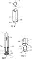
- FIG 4 is an exploded perspective view of the outer body 3.
- the outer body 3 comprises a tubular base section 3.1 and a cap part 3.2 for closing the proximal end of the base section 3.1.
- the cap part 3.2 is engageable to the base section 3.1 by a snap fit 3.3 (cf. fig. 3 ).
- the base section 3.1 comprises two ribs 3.4 (cf. fig. 2 ) extending inwardly from an inner surface of the base section 3.1 on opposite sides for respectively sliding along a guiding slot 2.1 in the support body (cf. fig. 1 ).
- the cap part 3.2 has a central peg 3.5 for engaging the plunger rod 8 when the drug delivery device 1 is assembled.
- the central peg 3.5 may either abut the plunger rod 8 or be attached to it.
- the outer body 3 is movable in a distal direction D and in a proximal direction P with respect to the support body 2.
- the syringe barrel 5 is inserted into the support body 2.
- a proximal barrel collar 5.1 sometimes referred to as a finger flange, on the syringe barrel 5 serves for attaching the syringe barrel 5 to the support body 2 by distally abutting an internal rib 2.4 in the support body 2 so that the syringe barrel 5 is fixed towards the distal direction D in its axial position with respect to the support body 2.
- the syringe barrel 5 is also fixed towards the proximal direction P by two resilient non-return clips 2.5 which are deflected by the barrel collar 5.1 when assembling the syringe barrel 5 into the support body 2 and snap in place once the barrel collar 5.1 has passed them thus facilitating assembly.
- Figure 5 is a longitudinal section of the support body 2.
- the support body 2 comprises a indicator ring 2.2 in the shape of radially outwards protruding and essentially circumferential rib.
- the indicator ring 2.2 may cover part of or the whole circumference of the support body 2.
- the indicator ring 2.2 is arranged to interact with the needle shield 4 so as to limit distal movement of the support body 2 with respect to the needle shield 4.
- a guiding track 2.3 is arranged in an outer surface of the support body 2 at the distal end for interacting with the needle shield 4 for limiting axial movement of the support body 2 with respect to the needle shield 4 .
- the guiding track 2.3 comprises a distal inclined section 2.3.1, a longitudinal section 2.3.2, a proximal inclined section 2.3.3 and a non-return catch 2.3.4.
- a distal inclined section 2.3.1 Near the proximal end of the support body 2 two resilient snap arms 2.6 for interacting with the outer body 3 are arranged.
- the resilient snap arms 2.6 initially engage the outer body 3 near its distal end in such a manner that the outer body 3 and the support body 2 are axially coupled unless a first detent force is applied, which deforms the resilient snap arms 2.6 so that the outer body 3 decouples from the support body 2 and can move relative to the support body 2 in the distal direction D.
- FIG. 6 is an exploded perspective view of the needle shield 4.
- the needle shield 4 comprises a tubular body section 4.1 and a cap part 4.2 with a central opening 4.3.
- the cap part 4.2 is engaged to the body section 4.1 by a snap fit 4.4 (cf. fig. 3 ) thus preventing relative axial movement.
- Two resilient retaining clips 4.5 with a respective inward protrusion 4.7 are arranged on the cap part 4.2.
- the inward protrusions 4.7 engage the guiding track 2.3 in the support body 2 so as to restrict relative axial movement between the needle shield 4 and the support body 2.
- a protective needle boot (not illustrated) may be positioned in and/or through the central opening 4.3 of the cap part 4.2 before and after an injection.
- the cap part 4.2 is rotationally locked to the body section 4.1. This may be achieved by the cap part 4.2 having a non-circular, e.g. elliptical cross section engaging in a corresponding opening in the body section 4.1.
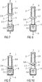
- Figure 7 is a lateral view of the drug delivery device 1 prior to an injection.
- the outer body 3 is fully extended in the proximal direction P from the support body 2.
- the needle shield 4 is fully extended from the support body 2 in the distal direction D.
- the injection needle 6 is in a retracted position within the needle shield 4.
- the needle shield spring 9 is relaxed. In this situation the inward protrusion 4.7 is located distally from the distal inclined section 2.3.1 of the guiding track 2.3 so that the resilient retaining clips 4.5 are also relaxed.
- a user may grab the outer body 3 and push the proximal end of the needle shield 6 against an injection site, e.g. a patient's skin.
- the force from the user's hand is resolved through the outer body 3, the resilient snap arm 2.6, the support body 2, the inclined section 2.3.1 of the guiding track 2.3 and the retaining clips 4.5 into the needle shield 4.
- the retaining clips 4.5 engaging the inclined section 2.3.1 of the guiding track 2.3 provide a second detent force which has to be overcome in order to move the needle shield 4 against the support body 2.
- the needle shield 4 is moved in the proximal direction P with respect to the support body 2 and all other parts of the drug delivery device 1 thereby also compressing the needle shield spring 9 so that the drug delivery device 1 arrives in a state as illustrated in figure 8 .
- the retaining clips 4.5 are deflected in a first tangential direction T1 by the inclined section 2.3.1 and the inward protrusions 4.7 travel up the longitudinal section 2.3.2 in the proximal direction P. Once the inward protrusion 4.7 has travelled proximally beyond the longitudinal section 2.3.2 the retaining clips 4.5 are no longer deflected.
- the first detent force is greater than the sum of the second detent force and the counteracting force of the needle shield spring 9 at full depression of the needle shield 4 such that on application of the drug delivery device 1 against the patient's skin the needle shield 4 always moves prior to the outer body 3 relative to the support body 2.This movement is opposed by the friction force of the injection needle 6 when penetrating the skin.
- the friction force of the needle 6 must be less than the counteracting force of the stopper 7 due to friction between the stopper 7 and the inner wall of the syringe 5 and due to the hydrostatic resistance of the drug to be displaced through the hollow needle 6, which depends on the inner diameter of the needle 6 and the viscosity of the drug.
- the needle insertion depth is defined by the needle shield 4 abutting the indicator ring 2.2. The mating surfaces of the indicator ring 2.2 and the needle shield 4 visually and haptically indicate to the user that they are intended to be pushed completely together in order to correctly apply the drug delivery device 1.
- the needle shield 4 is no longer pushed against the skin and is hence extended in the distal direction D relative to the other components of the drug delivery device 1 by the needle shield spring 9 such that the injection needle 6 arrives fully inside the needle shield 4 as illustrated in figure 10 .
- the inward protrusion 4.7 engages the proximal inclined section 2.3.3 and is deflected in a second tangential direction T2 opposed to the first tangential direction T1.
- the retaining clips 4.5 are no longer deflected. Hence, they will relax into the catch 2.3.4 thus locking the needle shield 4 in position relative to the support body 2 .
- the inward protrusion 4.7 and the retaining clips 4.5 are neither accessible for the user nor can they be deflected out of the catch 2.3.4 in any other way. Hence, the needle shield 4 is prevented from being depressed once more without destroying the drug delivery device 1.
- the end of the outer body 3 coupled to the support body 2 may comprise a radially outwards directed flange 3.6 thus improving ergonomics when applying the drug delivery device 1.
- a direction indicator 3.7 designed as a profiled cavity or concavity in the surface of the outer body 3 is arranged in the range of the flange 3.6.
- the needle shield 4 may likewise comprise a direction indicator 4.6.
- a label retaining recess 3.8 may be arranged in the outer body 3 for receiving a label which may be customized to the drug to be delivered and/or to the provider of the drug.
- Figure 11 is a schematic view of the drug delivery device 1 with a boot remover 10 for removing the protective needle boot prior to an injection.
- the boot remover 10 may be arranged to engage the needle boot by friction or by means of barbs.
- the boot remover 10 comprises a handle extending from the opening 4.3 for facilitating boot removal.
- a direction indicator 10.1 may be provided on the boot remover 10 for indicating the direction in which the user has to move the boot remover 10 for removing the protective needle boot.
Landscapes
- Health & Medical Sciences (AREA)
- Engineering & Computer Science (AREA)
- Heart & Thoracic Surgery (AREA)
- Vascular Medicine (AREA)
- Anesthesiology (AREA)
- Biomedical Technology (AREA)
- Hematology (AREA)
- Life Sciences & Earth Sciences (AREA)
- Animal Behavior & Ethology (AREA)
- General Health & Medical Sciences (AREA)
- Public Health (AREA)
- Veterinary Medicine (AREA)
- Environmental & Geological Engineering (AREA)
- Infusion, Injection, And Reservoir Apparatuses (AREA)
Claims (14)
- Medikamenten-Verabreichungsvorrichtung (1) zum Einstellen und Abgeben einer Dosis eines Medikaments, aufweisend:- einen Stützkörper (2) mit einem ersten Ende, das eine erste Öffnung definiert, und einem zweiten Ende, das eine zweite Öffnung definiert, und einen äußeren Anzeigering (2.2),- einen Spritzenzylinder (5), der mit einem Stopfen (7) abgedichtet ist, der entlang einer axialen Richtung verschiebbar darin angeordnet ist, wobei der Spritzenzylinder (5) dazu ausgeführt ist, eine integrierte Nadel (6) aufzuweisen oder mit einer Nadelanordnung gekoppelt zu sein, wobei der Spritzenzylinder (5) in dem Stützkörper (2) positioniert ist,- einen Nadelschutz (4), der dazu ausgeführt ist, an eines der Enden des Stützkörpers (2) gekoppelt und verschiebbar darauf angeordnet zu sein,- einen äußeren Körper (3), der dazu ausgeführt ist, an das andere Ende des Stützkörpers (2) gekoppelt und verschiebbar darauf angeordnet zu sein,
wobei der äußere Anzeigering (2.2) in der Form einer radial nach außen vorragenden und im Wesentlichen in Umfangsrichtung verlaufenden Rippe vorliegt,- wobei der äußere Anzeigering (2.2) die Bewegung sowohl des äußeren Körpers (3) als auch des Nadelschutzes (4) begrenzt,- wobei die Nadeleinführtiefe durch das Anliegen des Nadelschutzes (4) an dem Anzeigering (2.2) definiert wird,
dadurch gekennzeichnet, dass der äußere Anzeigering (2.2) ein zentrierter äußerer Anzeigering (2.2) ist, wobei das an den Stützkörper (2) gekoppelte Ende des äußeren Körpers (3) und das an den Stützkörper (2) gekoppelte Ende des Nadelschutzes (4) Passflächen haben, wobei die Passflächen auch mit der Gestalt des Anzeigerings (2.2) zusammenpassen, wodurch dem Benutzer gegenüber visuell und haptisch angegeben wird, dass die jeweiligen Teile dazu gedacht sind, vollständig zusammengeschoben zu werden, so dass die Passteile aneinander anliegen, um die Medikamenten-Verabreichungsvorrichtung (1) korrekt anzuwenden. - Medikamenten-Verabreichungsvorrichtung (1) nach Anspruch 1, wobei der äußere Anzeigering (2.2) gekrümmt ist.
- Medikamenten-Verabreichungsvorrichtung (1) nach einem der Ansprüche 1 oder 2, wobei ein erster Rastmechanismus angeordnet ist, um eine Bewegung des äußeren Körpers (3) relativ zu dem Stützkörper (2) einzuschränken, indem er dieser Bewegung mit einer ersten Rastkraft entgegenwirkt.
- Medikamenten-Verabreichungsvorrichtung (1) nach einem der vorhergehenden Ansprüche, wobei ein zweiter Rastmechanismus angeordnet ist, um eine Bewegung des Nadelschutzes (4) relativ zu dem Stützkörper (2) einzuschränken, indem er dieser Bewegung mit einer zweiten Rastkraft entgegenwirkt.
- Medikamenten-Verabreichungsvorrichtung (1) nach Anspruch 4, wobei die erste Rastkraft größer als eine Summe der zweiten Rastkraft und einer entgegenwirkenden Kraft einer Nadelschutzfeder (9) ist, die dazu angeordnet ist, den Nadelschutz (4) gegen den Stützkörper (2) vorzuspannen.
- Medikamenten-Verabreichungsvorrichtung (1) nach einem der Ansprüche 4 oder 5, wobei der zweite Rastmechanismus zumindest eine Führungsspur (2.3), die an dem Stützkörper (2) definiert ist, und zumindest einen mittels der Führungsspur (2.3) ablenkbaren Halteclip (4.5) an dem Nadelschutz (4) aufweist, wobei die Führungsspur (2.3) so ausgestaltet ist, dass der Halteclip (4.5) einer ersten Bahn folgt, wenn der Nadelschutz (4) zum Nadelauszug niedergedrückt wird, und einer anderen zweiten Bahn folgt, wenn der Nadelschutz (4) anschließend ausgezogen wird, wobei eine Rücklaufsperrfalle (2.3.4) zum Sperren des Halteclips (4.5) an dem Ende der zweiten Bahn angeordnet ist.
- Medikamenten-Verabreichungsvorrichtung (1) nach einem der vorhergehenden Ansprüche, wobei der Stützkörper (2) äußere Führungsmittel aufweist, die radial nach außen vorragen, um die Bewegung des äußeren Körpers (3) zu führen.
- Medikamenten-Verabreichungsvorrichtung (1) nach einem der vorhergehenden Ansprüche, wobei der Stützkörper (2) einen Führungsschlitz (2.1) aufweist, der in der Wand des Stützkörpers (2) angeordnet ist, um die Bewegung des Nadelschutzes (4) zu führen.
- Medikamenten-Verabreichungsvorrichtung (1) nach einem der vorhergehenden Ansprüche, aufweisend eine an den Stopfen (7) gekoppelte Kolbenstange (8), wobei ein proximaler Abschnitt der Kolbenstange (8) für die Koppelung an den äußeren Körper (3) ausgeführt ist.
- Medikamenten-Verabreichungsvorrichtung (1) nach einem der vorhergehenden Ansprüche, wobei der Nadelschutz (4) zumindest einen Körperabschnitt (4.1) und einen Kappenteil (4.2) aufweist.
- Medikamenten-Verabreichungsvorrichtung (1) nach einem der vorhergehenden Ansprüche, wobei der äußere Körper (3) als ein Einzelteil ausgebildet ist oder wobei der äußere Körper (3) zumindest einen Basisabschnitt (3.1) und einen Kappenteil (3.2) aufweist.
- Medikamenten-Verabreichungsvorrichtung (1) nach einem der vorhergehenden Ansprüche, wobei das an den Stützkörper (2) gekoppelte Ende des äußeren Körpers (3) einen radial nach außen gerichteten Flansch (3.6) aufweist.
- Medikamenten-Verabreichungsvorrichtung (1) nach Anspruch 11, wobei eine Richtungsanzeige (3.7), die als ein profilierter Hohlraum oder eine profilierte Konkavität in der Oberfläche des äußeren Körpers (3) ausgelegt ist, an dem äußeren Körper (3) in dem Bereich des Flanschs angeordnet ist.
- Medikamenten-Verabreichungsvorrichtung (1) nach einem der vorhergehenden Ansprüche, wobei der Nadelschutz (4) eine Richtungsanzeige (4.6) aufweist.
Priority Applications (1)
| Application Number | Priority Date | Filing Date | Title |
|---|---|---|---|
| EP13737290.0A EP2874683B1 (de) | 2012-07-17 | 2013-07-17 | Arzneimittelabgabevorrichtung |
Applications Claiming Priority (4)
| Application Number | Priority Date | Filing Date | Title |
|---|---|---|---|
| EP20120176674 EP2687251A1 (de) | 2012-07-17 | 2012-07-17 | Arzneimittelabgabevorrichtung |
| US201261714984P | 2012-10-17 | 2012-10-17 | |
| EP13737290.0A EP2874683B1 (de) | 2012-07-17 | 2013-07-17 | Arzneimittelabgabevorrichtung |
| PCT/EP2013/065128 WO2014012994A1 (en) | 2012-07-17 | 2013-07-17 | Drug delivery device |
Publications (2)
| Publication Number | Publication Date |
|---|---|
| EP2874683A1 EP2874683A1 (de) | 2015-05-27 |
| EP2874683B1 true EP2874683B1 (de) | 2021-01-13 |
Family
ID=46651376
Family Applications (2)
| Application Number | Title | Priority Date | Filing Date |
|---|---|---|---|
| EP20120176674 Ceased EP2687251A1 (de) | 2012-07-17 | 2012-07-17 | Arzneimittelabgabevorrichtung |
| EP13737290.0A Active EP2874683B1 (de) | 2012-07-17 | 2013-07-17 | Arzneimittelabgabevorrichtung |
Family Applications Before (1)
| Application Number | Title | Priority Date | Filing Date |
|---|---|---|---|
| EP20120176674 Ceased EP2687251A1 (de) | 2012-07-17 | 2012-07-17 | Arzneimittelabgabevorrichtung |
Country Status (7)
| Country | Link |
|---|---|
| US (2) | US10039888B2 (de) |
| EP (2) | EP2687251A1 (de) |
| JP (1) | JP6367796B2 (de) |
| CN (1) | CN104470563A (de) |
| DK (1) | DK2874683T3 (de) |
| HK (1) | HK1206654A1 (de) |
| WO (1) | WO2014012994A1 (de) |
Cited By (2)
| Publication number | Priority date | Publication date | Assignee | Title |
|---|---|---|---|---|
| US11571518B2 (en) | 2018-05-25 | 2023-02-07 | Adamis Pharmaceuticals Corporation | Emergency devices |
| US12350473B2 (en) | 2018-05-25 | 2025-07-08 | Zmi Pharma Inc. | Emergency devices |
Families Citing this family (22)
| Publication number | Priority date | Publication date | Assignee | Title |
|---|---|---|---|---|
| CA2807552A1 (en) | 2010-08-06 | 2012-02-09 | Moderna Therapeutics, Inc. | Engineered nucleic acids and methods of use thereof |
| ES3005233T3 (en) | 2010-10-01 | 2025-03-14 | Modernatx Inc | Modified nucleosides, nucleotides, and nucleic acids, and uses thereof |
| JP2014511687A (ja) | 2011-03-31 | 2014-05-19 | モデルナ セラピューティクス インコーポレイテッド | 工学操作された核酸の送達および製剤 |
| US9464124B2 (en) | 2011-09-12 | 2016-10-11 | Moderna Therapeutics, Inc. | Engineered nucleic acids and methods of use thereof |
| EP2763701B1 (de) | 2011-10-03 | 2018-12-19 | Moderna Therapeutics, Inc. | Modifizierte nukleoside, nukleotide und nukleinsäuren und verwendungen davon |
| JP2015501844A (ja) | 2011-12-16 | 2015-01-19 | モデルナ セラピューティクス インコーポレイテッドModerna Therapeutics,Inc. | 修飾ヌクレオシド、ヌクレオチドおよび核酸組成物 |
| WO2013151663A1 (en) | 2012-04-02 | 2013-10-10 | modeRNA Therapeutics | Modified polynucleotides for the production of membrane proteins |
| US9283287B2 (en) | 2012-04-02 | 2016-03-15 | Moderna Therapeutics, Inc. | Modified polynucleotides for the production of nuclear proteins |
| US9254311B2 (en) | 2012-04-02 | 2016-02-09 | Moderna Therapeutics, Inc. | Modified polynucleotides for the production of proteins |
| US9572897B2 (en) | 2012-04-02 | 2017-02-21 | Modernatx, Inc. | Modified polynucleotides for the production of cytoplasmic and cytoskeletal proteins |
| ES2921623T3 (es) | 2012-11-26 | 2022-08-30 | Modernatx Inc | ARN modificado terminalmente |
| US8980864B2 (en) | 2013-03-15 | 2015-03-17 | Moderna Therapeutics, Inc. | Compositions and methods of altering cholesterol levels |
| KR20160067219A (ko) | 2013-10-03 | 2016-06-13 | 모더나 세라퓨틱스, 인코포레이티드 | 저밀도 지단백질 수용체를 암호화하는 폴리뉴클레오타이드 |
| EP2902061A1 (de) | 2014-01-30 | 2015-08-05 | Sanofi-Aventis Deutschland GmbH | Medikamentenabgabevorrichtung |
| CN114028655A (zh) * | 2015-08-24 | 2022-02-11 | 阿达米制药公司 | 注射器装置 |
| USD810282S1 (en) * | 2015-10-19 | 2018-02-13 | Carebay Europe Ltd | Medical injector |
| USD818575S1 (en) * | 2015-12-08 | 2018-05-22 | Becton Dickinson France S.A.S. | Medical injector with enhanced grip |
| EP3630231B1 (de) | 2017-05-25 | 2023-11-01 | West Pharmaceutical Services, Inc. | Smarte spritze mit nfc kommunikation und kapazitätsmessung |
| US11654252B2 (en) | 2017-09-29 | 2023-05-23 | West Pharmaceutical Services, Inc. | Housing with syringe holding feature |
| CN110681006A (zh) * | 2018-07-06 | 2020-01-14 | 群康生技股份有限公司 | 注射器 |
| WO2021050448A1 (en) * | 2019-09-09 | 2021-03-18 | West Pharmaceutical Services, Inc. | Track and locking mechanisms for injection device |
| JP7525955B2 (ja) | 2021-04-08 | 2024-07-31 | ラブ ライフサイエンシズ エルエルシー | プレフィルドシリンジ安全デバイスおよび注射器 |
Family Cites Families (22)
| Publication number | Priority date | Publication date | Assignee | Title |
|---|---|---|---|---|
| US3702608A (en) * | 1970-12-15 | 1972-11-14 | Robert C Tibbs | Painless injection device with powered plunger |
| JP3785186B2 (ja) | 1992-01-07 | 2006-06-14 | エスティーアイ インターナショナル リミテッド | 自動式注射器 |
| GB9200219D0 (en) * | 1992-01-07 | 1992-02-26 | Medimech Int Ltd | Automatic injectors |
| US5242401A (en) * | 1992-10-09 | 1993-09-07 | Colsky Andrew E | Disposable needle head assembly |
| EP0768902B1 (de) * | 1992-11-19 | 1998-07-15 | Tebro S.A. | Automatische injektionsvorrichtung für vorgefüllte spritzen |
| US5540664A (en) | 1993-05-27 | 1996-07-30 | Washington Biotech Corporation | Reloadable automatic or manual emergency injection system |
| DE4320463A1 (de) * | 1993-06-21 | 1994-12-22 | Boehringer Mannheim Gmbh | Blutlanzettenvorrichtung zur Entnahme von Blut für Diagnosezwecke |
| US5368568A (en) * | 1993-10-12 | 1994-11-29 | Pitts; Raymond H. | Disabling hypodermic syringe |
| US6569123B2 (en) * | 1999-10-14 | 2003-05-27 | Becton, Dickinson And Company | Prefillable intradermal injector |
| DE10203597A1 (de) * | 2002-01-30 | 2003-08-07 | Disetronic Licensing Ag | Injektionsgerät |
| WO2006079064A1 (en) * | 2005-01-24 | 2006-07-27 | Antares Pharma, Inc. | Prefilled needle assisted jet injector |
| ES2914825T3 (es) * | 2008-08-15 | 2022-06-16 | Becton Dickinson Co | Conjunto de aguja de pluma de seguridad |
| EP2403562B1 (de) | 2009-03-05 | 2020-11-25 | Sanofi-Aventis Deutschland GmbH | Arzneimittelabgabevorrichtung mit anzeige von benutzungsinformationen |
| WO2011047298A2 (en) | 2009-10-16 | 2011-04-21 | Centocor Ortho Biotech Inc. | Palm activated drug delivery device |
| US8758301B2 (en) * | 2009-12-15 | 2014-06-24 | Abbvie Biotechnology Ltd | Firing button for automatic injection device |
| RU2572738C2 (ru) * | 2010-07-02 | 2016-01-20 | Санофи-Авентис Дойчланд Гмбх | Защитное устройство для предварительно заполненного шприца и инъекционное устройство |
| MY166395A (en) * | 2010-07-02 | 2018-06-25 | Sanofi Aventis Deutschland | Safety device for a pre-filled syringe and injection device |
| CN103079616B (zh) | 2010-07-02 | 2015-08-12 | 赛诺菲-安万特德国有限公司 | 用于预装式注射器的安全装置和注射装置 |
| PL2588168T3 (pl) * | 2010-07-02 | 2015-08-31 | Sanofi Aventis Deutschland | Urządzenie zabezpieczające do wstępnie napełnionej strzykawki oraz urządzenie iniekcyjne |
| JP5923097B2 (ja) * | 2010-10-25 | 2016-05-24 | サノフィ−アベンティス・ドイチュラント・ゲゼルシャフト・ミット・ベシュレンクテル・ハフツング | 安全デバイス |
| US9173999B2 (en) * | 2011-01-26 | 2015-11-03 | Kaleo, Inc. | Devices and methods for delivering medicaments from a multi-chamber container |
| US20130144255A1 (en) * | 2011-12-06 | 2013-06-06 | Robert J. Cohn | Syringe assemblies including a safety shield for a needle |
-
2012
- 2012-07-17 EP EP20120176674 patent/EP2687251A1/de not_active Ceased
-
2013
- 2013-07-17 DK DK13737290.0T patent/DK2874683T3/da active
- 2013-07-17 WO PCT/EP2013/065128 patent/WO2014012994A1/en not_active Ceased
- 2013-07-17 JP JP2015522089A patent/JP6367796B2/ja not_active Expired - Fee Related
- 2013-07-17 HK HK15107311.0A patent/HK1206654A1/xx unknown
- 2013-07-17 EP EP13737290.0A patent/EP2874683B1/de active Active
- 2013-07-17 US US14/412,731 patent/US10039888B2/en active Active
- 2013-07-17 CN CN201380037580.5A patent/CN104470563A/zh active Pending
-
2018
- 2018-08-06 US US16/055,863 patent/US10960145B2/en active Active
Non-Patent Citations (1)
| Title |
|---|
| None * |
Cited By (2)
| Publication number | Priority date | Publication date | Assignee | Title |
|---|---|---|---|---|
| US11571518B2 (en) | 2018-05-25 | 2023-02-07 | Adamis Pharmaceuticals Corporation | Emergency devices |
| US12350473B2 (en) | 2018-05-25 | 2025-07-08 | Zmi Pharma Inc. | Emergency devices |
Also Published As
| Publication number | Publication date |
|---|---|
| CN104470563A (zh) | 2015-03-25 |
| WO2014012994A1 (en) | 2014-01-23 |
| US10960145B2 (en) | 2021-03-30 |
| US20150148744A1 (en) | 2015-05-28 |
| DK2874683T3 (da) | 2021-04-12 |
| JP2016503308A (ja) | 2016-02-04 |
| EP2687251A1 (de) | 2014-01-22 |
| EP2874683A1 (de) | 2015-05-27 |
| HK1206654A1 (en) | 2016-01-15 |
| JP6367796B2 (ja) | 2018-08-01 |
| US10039888B2 (en) | 2018-08-07 |
| US20190009038A1 (en) | 2019-01-10 |
Similar Documents
| Publication | Publication Date | Title |
|---|---|---|
| US10960145B2 (en) | Drug delivery device | |
| EP2874684B1 (de) | Arzneimittelabgabevorrichtung | |
| EP3074069B1 (de) | Muffenabzieher | |
| US20190351149A1 (en) | Boot remover | |
| EP2661299B1 (de) | Sicherheitsvorrichtung für eine vorgefüllte spritze und injektionsvorrichtung | |
| US10857307B2 (en) | Medicament delivery device and method for assembling same | |
| US9592350B2 (en) | Safety device for a pre-filled syringe and an injection device | |
| HK1244238A1 (en) | Medicament delivery device and method for assembling same | |
| EP3335751B1 (de) | Sicherheitsvorrichtung für einen medikamentenbehälter | |
| US20150367082A1 (en) | Drug delivery device | |
| EP3099357B1 (de) | Medikamentenabgabevorrichtung | |
| HK1206655B (en) | Drug delivery device | |
| HK1227330B (en) | Medicament delivery device | |
| HK1187007B (en) | A safety device for a pre-filled syringe and an injection device |
Legal Events
| Date | Code | Title | Description |
|---|---|---|---|
| PUAI | Public reference made under article 153(3) epc to a published international application that has entered the european phase |
Free format text: ORIGINAL CODE: 0009012 |
|
| 17P | Request for examination filed |
Effective date: 20150217 |
|
| AK | Designated contracting states |
Kind code of ref document: A1 Designated state(s): AL AT BE BG CH CY CZ DE DK EE ES FI FR GB GR HR HU IE IS IT LI LT LU LV MC MK MT NL NO PL PT RO RS SE SI SK SM TR |
|
| AX | Request for extension of the european patent |
Extension state: BA ME |
|
| DAX | Request for extension of the european patent (deleted) | ||
| REG | Reference to a national code |
Ref country code: HK Ref legal event code: DE Ref document number: 1206654 Country of ref document: HK |
|
| STAA | Information on the status of an ep patent application or granted ep patent |
Free format text: STATUS: EXAMINATION IS IN PROGRESS |
|
| 17Q | First examination report despatched |
Effective date: 20180524 |
|
| REG | Reference to a national code |
Ref country code: DE Ref legal event code: R079 Ref document number: 602013075289 Country of ref document: DE Free format text: PREVIOUS MAIN CLASS: A61M0005320000 Ipc: A61M0005310000 |
|
| GRAP | Despatch of communication of intention to grant a patent |
Free format text: ORIGINAL CODE: EPIDOSNIGR1 |
|
| STAA | Information on the status of an ep patent application or granted ep patent |
Free format text: STATUS: GRANT OF PATENT IS INTENDED |
|
| RIC1 | Information provided on ipc code assigned before grant |
Ipc: A61M 5/31 20060101AFI20201008BHEP Ipc: A61M 5/46 20060101ALI20201008BHEP Ipc: A61M 5/32 20060101ALI20201008BHEP |
|
| INTG | Intention to grant announced |
Effective date: 20201030 |
|
| GRAS | Grant fee paid |
Free format text: ORIGINAL CODE: EPIDOSNIGR3 |
|
| GRAA | (expected) grant |
Free format text: ORIGINAL CODE: 0009210 |
|
| STAA | Information on the status of an ep patent application or granted ep patent |
Free format text: STATUS: THE PATENT HAS BEEN GRANTED |
|
| AK | Designated contracting states |
Kind code of ref document: B1 Designated state(s): AL AT BE BG CH CY CZ DE DK EE ES FI FR GB GR HR HU IE IS IT LI LT LU LV MC MK MT NL NO PL PT RO RS SE SI SK SM TR |
|
| REG | Reference to a national code |
Ref country code: GB Ref legal event code: FG4D |
|
| REG | Reference to a national code |
Ref country code: CH Ref legal event code: EP |
|
| REG | Reference to a national code |
Ref country code: IE Ref legal event code: FG4D |
|
| REG | Reference to a national code |
Ref country code: DE Ref legal event code: R096 Ref document number: 602013075289 Country of ref document: DE |
|
| REG | Reference to a national code |
Ref country code: AT Ref legal event code: REF Ref document number: 1354078 Country of ref document: AT Kind code of ref document: T Effective date: 20210215 |
|
| REG | Reference to a national code |
Ref country code: DK Ref legal event code: T3 Effective date: 20210406 |
|
| REG | Reference to a national code |
Ref country code: AT Ref legal event code: MK05 Ref document number: 1354078 Country of ref document: AT Kind code of ref document: T Effective date: 20210113 |
|
| REG | Reference to a national code |
Ref country code: NL Ref legal event code: MP Effective date: 20210113 |
|
| REG | Reference to a national code |
Ref country code: LT Ref legal event code: MG9D |
|
| PG25 | Lapsed in a contracting state [announced via postgrant information from national office to epo] |
Ref country code: NL Free format text: LAPSE BECAUSE OF FAILURE TO SUBMIT A TRANSLATION OF THE DESCRIPTION OR TO PAY THE FEE WITHIN THE PRESCRIBED TIME-LIMIT Effective date: 20210113 Ref country code: NO Free format text: LAPSE BECAUSE OF FAILURE TO SUBMIT A TRANSLATION OF THE DESCRIPTION OR TO PAY THE FEE WITHIN THE PRESCRIBED TIME-LIMIT Effective date: 20210413 Ref country code: BG Free format text: LAPSE BECAUSE OF FAILURE TO SUBMIT A TRANSLATION OF THE DESCRIPTION OR TO PAY THE FEE WITHIN THE PRESCRIBED TIME-LIMIT Effective date: 20210413 Ref country code: GR Free format text: LAPSE BECAUSE OF FAILURE TO SUBMIT A TRANSLATION OF THE DESCRIPTION OR TO PAY THE FEE WITHIN THE PRESCRIBED TIME-LIMIT Effective date: 20210414 Ref country code: HR Free format text: LAPSE BECAUSE OF FAILURE TO SUBMIT A TRANSLATION OF THE DESCRIPTION OR TO PAY THE FEE WITHIN THE PRESCRIBED TIME-LIMIT Effective date: 20210113 Ref country code: FI Free format text: LAPSE BECAUSE OF FAILURE TO SUBMIT A TRANSLATION OF THE DESCRIPTION OR TO PAY THE FEE WITHIN THE PRESCRIBED TIME-LIMIT Effective date: 20210113 Ref country code: PT Free format text: LAPSE BECAUSE OF FAILURE TO SUBMIT A TRANSLATION OF THE DESCRIPTION OR TO PAY THE FEE WITHIN THE PRESCRIBED TIME-LIMIT Effective date: 20210513 Ref country code: LT Free format text: LAPSE BECAUSE OF FAILURE TO SUBMIT A TRANSLATION OF THE DESCRIPTION OR TO PAY THE FEE WITHIN THE PRESCRIBED TIME-LIMIT Effective date: 20210113 |
|
| PG25 | Lapsed in a contracting state [announced via postgrant information from national office to epo] |
Ref country code: PL Free format text: LAPSE BECAUSE OF FAILURE TO SUBMIT A TRANSLATION OF THE DESCRIPTION OR TO PAY THE FEE WITHIN THE PRESCRIBED TIME-LIMIT Effective date: 20210113 Ref country code: RS Free format text: LAPSE BECAUSE OF FAILURE TO SUBMIT A TRANSLATION OF THE DESCRIPTION OR TO PAY THE FEE WITHIN THE PRESCRIBED TIME-LIMIT Effective date: 20210113 Ref country code: LV Free format text: LAPSE BECAUSE OF FAILURE TO SUBMIT A TRANSLATION OF THE DESCRIPTION OR TO PAY THE FEE WITHIN THE PRESCRIBED TIME-LIMIT Effective date: 20210113 Ref country code: AT Free format text: LAPSE BECAUSE OF FAILURE TO SUBMIT A TRANSLATION OF THE DESCRIPTION OR TO PAY THE FEE WITHIN THE PRESCRIBED TIME-LIMIT Effective date: 20210113 Ref country code: SE Free format text: LAPSE BECAUSE OF FAILURE TO SUBMIT A TRANSLATION OF THE DESCRIPTION OR TO PAY THE FEE WITHIN THE PRESCRIBED TIME-LIMIT Effective date: 20210113 |
|
| PG25 | Lapsed in a contracting state [announced via postgrant information from national office to epo] |
Ref country code: IS Free format text: LAPSE BECAUSE OF FAILURE TO SUBMIT A TRANSLATION OF THE DESCRIPTION OR TO PAY THE FEE WITHIN THE PRESCRIBED TIME-LIMIT Effective date: 20210513 |
|
| REG | Reference to a national code |
Ref country code: DE Ref legal event code: R097 Ref document number: 602013075289 Country of ref document: DE |
|
| PG25 | Lapsed in a contracting state [announced via postgrant information from national office to epo] |
Ref country code: SM Free format text: LAPSE BECAUSE OF FAILURE TO SUBMIT A TRANSLATION OF THE DESCRIPTION OR TO PAY THE FEE WITHIN THE PRESCRIBED TIME-LIMIT Effective date: 20210113 Ref country code: CZ Free format text: LAPSE BECAUSE OF FAILURE TO SUBMIT A TRANSLATION OF THE DESCRIPTION OR TO PAY THE FEE WITHIN THE PRESCRIBED TIME-LIMIT Effective date: 20210113 Ref country code: EE Free format text: LAPSE BECAUSE OF FAILURE TO SUBMIT A TRANSLATION OF THE DESCRIPTION OR TO PAY THE FEE WITHIN THE PRESCRIBED TIME-LIMIT Effective date: 20210113 |
|
| PLBE | No opposition filed within time limit |
Free format text: ORIGINAL CODE: 0009261 |
|
| STAA | Information on the status of an ep patent application or granted ep patent |
Free format text: STATUS: NO OPPOSITION FILED WITHIN TIME LIMIT |
|
| PG25 | Lapsed in a contracting state [announced via postgrant information from national office to epo] |
Ref country code: SK Free format text: LAPSE BECAUSE OF FAILURE TO SUBMIT A TRANSLATION OF THE DESCRIPTION OR TO PAY THE FEE WITHIN THE PRESCRIBED TIME-LIMIT Effective date: 20210113 Ref country code: ES Free format text: LAPSE BECAUSE OF FAILURE TO SUBMIT A TRANSLATION OF THE DESCRIPTION OR TO PAY THE FEE WITHIN THE PRESCRIBED TIME-LIMIT Effective date: 20210113 Ref country code: RO Free format text: LAPSE BECAUSE OF FAILURE TO SUBMIT A TRANSLATION OF THE DESCRIPTION OR TO PAY THE FEE WITHIN THE PRESCRIBED TIME-LIMIT Effective date: 20210113 |
|
| 26N | No opposition filed |
Effective date: 20211014 |
|
| PG25 | Lapsed in a contracting state [announced via postgrant information from national office to epo] |
Ref country code: AL Free format text: LAPSE BECAUSE OF FAILURE TO SUBMIT A TRANSLATION OF THE DESCRIPTION OR TO PAY THE FEE WITHIN THE PRESCRIBED TIME-LIMIT Effective date: 20210113 |
|
| REG | Reference to a national code |
Ref country code: HK Ref legal event code: WD Ref document number: 1206654 Country of ref document: HK |
|
| PG25 | Lapsed in a contracting state [announced via postgrant information from national office to epo] |
Ref country code: SI Free format text: LAPSE BECAUSE OF FAILURE TO SUBMIT A TRANSLATION OF THE DESCRIPTION OR TO PAY THE FEE WITHIN THE PRESCRIBED TIME-LIMIT Effective date: 20210113 |
|
| PG25 | Lapsed in a contracting state [announced via postgrant information from national office to epo] |
Ref country code: MC Free format text: LAPSE BECAUSE OF FAILURE TO SUBMIT A TRANSLATION OF THE DESCRIPTION OR TO PAY THE FEE WITHIN THE PRESCRIBED TIME-LIMIT Effective date: 20210113 |
|
| REG | Reference to a national code |
Ref country code: BE Ref legal event code: MM Effective date: 20210731 |
|
| PG25 | Lapsed in a contracting state [announced via postgrant information from national office to epo] |
Ref country code: IT Free format text: LAPSE BECAUSE OF FAILURE TO SUBMIT A TRANSLATION OF THE DESCRIPTION OR TO PAY THE FEE WITHIN THE PRESCRIBED TIME-LIMIT Effective date: 20210113 |
|
| PG25 | Lapsed in a contracting state [announced via postgrant information from national office to epo] |
Ref country code: IS Free format text: LAPSE BECAUSE OF FAILURE TO SUBMIT A TRANSLATION OF THE DESCRIPTION OR TO PAY THE FEE WITHIN THE PRESCRIBED TIME-LIMIT Effective date: 20210513 Ref country code: LU Free format text: LAPSE BECAUSE OF NON-PAYMENT OF DUE FEES Effective date: 20210717 |
|
| PG25 | Lapsed in a contracting state [announced via postgrant information from national office to epo] |
Ref country code: IE Free format text: LAPSE BECAUSE OF NON-PAYMENT OF DUE FEES Effective date: 20210717 Ref country code: BE Free format text: LAPSE BECAUSE OF NON-PAYMENT OF DUE FEES Effective date: 20210731 |
|
| PG25 | Lapsed in a contracting state [announced via postgrant information from national office to epo] |
Ref country code: HU Free format text: LAPSE BECAUSE OF FAILURE TO SUBMIT A TRANSLATION OF THE DESCRIPTION OR TO PAY THE FEE WITHIN THE PRESCRIBED TIME-LIMIT; INVALID AB INITIO Effective date: 20130717 |
|
| PG25 | Lapsed in a contracting state [announced via postgrant information from national office to epo] |
Ref country code: CY Free format text: LAPSE BECAUSE OF FAILURE TO SUBMIT A TRANSLATION OF THE DESCRIPTION OR TO PAY THE FEE WITHIN THE PRESCRIBED TIME-LIMIT Effective date: 20210113 |
|
| PG25 | Lapsed in a contracting state [announced via postgrant information from national office to epo] |
Ref country code: MK Free format text: LAPSE BECAUSE OF FAILURE TO SUBMIT A TRANSLATION OF THE DESCRIPTION OR TO PAY THE FEE WITHIN THE PRESCRIBED TIME-LIMIT Effective date: 20210113 |
|
| PGFP | Annual fee paid to national office [announced via postgrant information from national office to epo] |
Ref country code: GB Payment date: 20240530 Year of fee payment: 12 |
|
| PGFP | Annual fee paid to national office [announced via postgrant information from national office to epo] |
Ref country code: FR Payment date: 20240611 Year of fee payment: 12 |
|
| PG25 | Lapsed in a contracting state [announced via postgrant information from national office to epo] |
Ref country code: MT Free format text: LAPSE BECAUSE OF FAILURE TO SUBMIT A TRANSLATION OF THE DESCRIPTION OR TO PAY THE FEE WITHIN THE PRESCRIBED TIME-LIMIT Effective date: 20210113 |
|
| PGFP | Annual fee paid to national office [announced via postgrant information from national office to epo] |
Ref country code: DE Payment date: 20240604 Year of fee payment: 12 |
|
| PGFP | Annual fee paid to national office [announced via postgrant information from national office to epo] |
Ref country code: DK Payment date: 20240712 Year of fee payment: 12 |
|
| PGFP | Annual fee paid to national office [announced via postgrant information from national office to epo] |
Ref country code: CH Payment date: 20240801 Year of fee payment: 12 |
|
| PGFP | Annual fee paid to national office [announced via postgrant information from national office to epo] |
Ref country code: TR Payment date: 20240704 Year of fee payment: 12 |
|
| REG | Reference to a national code |
Ref country code: DE Ref legal event code: R119 Ref document number: 602013075289 Country of ref document: DE |
|
| REG | Reference to a national code |
Ref country code: DK Ref legal event code: EBP Effective date: 20250731 |
|
| REG | Reference to a national code |
Ref country code: CH Ref legal event code: H13 Free format text: ST27 STATUS EVENT CODE: U-0-0-H10-H13 (AS PROVIDED BY THE NATIONAL OFFICE) Effective date: 20260224 |
|
| GBPC | Gb: european patent ceased through non-payment of renewal fee |
Effective date: 20250717 |
|
| PG25 | Lapsed in a contracting state [announced via postgrant information from national office to epo] |
Ref country code: GB Free format text: LAPSE BECAUSE OF NON-PAYMENT OF DUE FEES Effective date: 20250717 |
|
| PG25 | Lapsed in a contracting state [announced via postgrant information from national office to epo] |
Ref country code: DE Free format text: LAPSE BECAUSE OF NON-PAYMENT OF DUE FEES Effective date: 20260203 |
|
| PG25 | Lapsed in a contracting state [announced via postgrant information from national office to epo] |
Ref country code: FR Free format text: LAPSE BECAUSE OF NON-PAYMENT OF DUE FEES Effective date: 20250731 |
|
| PG25 | Lapsed in a contracting state [announced via postgrant information from national office to epo] |
Ref country code: CH Free format text: LAPSE BECAUSE OF NON-PAYMENT OF DUE FEES Effective date: 20250731 |