EP2874583B1 - Pièce à main de phacoémulsification avec pompe d'aspiration et d'irrigation intégrée - Google Patents
Pièce à main de phacoémulsification avec pompe d'aspiration et d'irrigation intégrée Download PDFInfo
- Publication number
- EP2874583B1 EP2874583B1 EP13863111.4A EP13863111A EP2874583B1 EP 2874583 B1 EP2874583 B1 EP 2874583B1 EP 13863111 A EP13863111 A EP 13863111A EP 2874583 B1 EP2874583 B1 EP 2874583B1
- Authority
- EP
- European Patent Office
- Prior art keywords
- aspiration
- irrigation
- conduit
- pump
- fluid
- Prior art date
- Legal status (The legal status is an assumption and is not a legal conclusion. Google has not performed a legal analysis and makes no representation as to the accuracy of the status listed.)
- Active
Links
- 230000002262 irrigation Effects 0.000 title claims description 129
- 238000003973 irrigation Methods 0.000 title claims description 129
- 239000012530 fluid Substances 0.000 claims description 81
- 230000004410 intraocular pressure Effects 0.000 claims description 40
- 238000004891 communication Methods 0.000 claims description 12
- 238000001356 surgical procedure Methods 0.000 claims description 11
- 230000008859 change Effects 0.000 claims description 4
- 230000004913 activation Effects 0.000 claims description 3
- 238000000034 method Methods 0.000 description 27
- 210000000695 crystalline len Anatomy 0.000 description 14
- 230000007423 decrease Effects 0.000 description 10
- 230000001276 controlling effect Effects 0.000 description 4
- 230000002596 correlated effect Effects 0.000 description 4
- 238000001514 detection method Methods 0.000 description 4
- 238000010586 diagram Methods 0.000 description 4
- 230000000694 effects Effects 0.000 description 4
- 230000006870 function Effects 0.000 description 4
- 239000013078 crystal Substances 0.000 description 3
- 239000012634 fragment Substances 0.000 description 3
- 230000004044 response Effects 0.000 description 3
- 208000002177 Cataract Diseases 0.000 description 2
- 210000002159 anterior chamber Anatomy 0.000 description 2
- 210000004087 cornea Anatomy 0.000 description 2
- 230000003247 decreasing effect Effects 0.000 description 2
- 230000007812 deficiency Effects 0.000 description 2
- 238000004945 emulsification Methods 0.000 description 2
- 230000002572 peristaltic effect Effects 0.000 description 2
- 210000001525 retina Anatomy 0.000 description 2
- 230000003213 activating effect Effects 0.000 description 1
- 230000004075 alteration Effects 0.000 description 1
- 239000002775 capsule Substances 0.000 description 1
- 238000012937 correction Methods 0.000 description 1
- 230000000875 corresponding effect Effects 0.000 description 1
- 230000001934 delay Effects 0.000 description 1
- 230000003292 diminished effect Effects 0.000 description 1
- 201000010099 disease Diseases 0.000 description 1
- 208000037265 diseases, disorders, signs and symptoms Diseases 0.000 description 1
- 238000001990 intravenous administration Methods 0.000 description 1
- 229940113601 irrigation solution Drugs 0.000 description 1
- 238000004519 manufacturing process Methods 0.000 description 1
- 238000005259 measurement Methods 0.000 description 1
- 238000012986 modification Methods 0.000 description 1
- 230000004048 modification Effects 0.000 description 1
- 230000010355 oscillation Effects 0.000 description 1
- 230000002265 prevention Effects 0.000 description 1
- 230000008569 process Effects 0.000 description 1
- 230000001737 promoting effect Effects 0.000 description 1
- 238000005086 pumping Methods 0.000 description 1
- 238000011144 upstream manufacturing Methods 0.000 description 1
Images

Classifications
-
- A—HUMAN NECESSITIES
- A61—MEDICAL OR VETERINARY SCIENCE; HYGIENE
- A61F—FILTERS IMPLANTABLE INTO BLOOD VESSELS; PROSTHESES; DEVICES PROVIDING PATENCY TO, OR PREVENTING COLLAPSING OF, TUBULAR STRUCTURES OF THE BODY, e.g. STENTS; ORTHOPAEDIC, NURSING OR CONTRACEPTIVE DEVICES; FOMENTATION; TREATMENT OR PROTECTION OF EYES OR EARS; BANDAGES, DRESSINGS OR ABSORBENT PADS; FIRST-AID KITS
- A61F9/00—Methods or devices for treatment of the eyes; Devices for putting-in contact lenses; Devices to correct squinting; Apparatus to guide the blind; Protective devices for the eyes, carried on the body or in the hand
- A61F9/007—Methods or devices for eye surgery
- A61F9/00736—Instruments for removal of intra-ocular material or intra-ocular injection, e.g. cataract instruments
- A61F9/00745—Instruments for removal of intra-ocular material or intra-ocular injection, e.g. cataract instruments using mechanical vibrations, e.g. ultrasonic
-
- A—HUMAN NECESSITIES
- A61—MEDICAL OR VETERINARY SCIENCE; HYGIENE
- A61M—DEVICES FOR INTRODUCING MEDIA INTO, OR ONTO, THE BODY; DEVICES FOR TRANSDUCING BODY MEDIA OR FOR TAKING MEDIA FROM THE BODY; DEVICES FOR PRODUCING OR ENDING SLEEP OR STUPOR
- A61M1/00—Suction or pumping devices for medical purposes; Devices for carrying-off, for treatment of, or for carrying-over, body-liquids; Drainage systems
- A61M1/71—Suction drainage systems
- A61M1/74—Suction control
- A61M1/743—Suction control by changing the cross-section of the line, e.g. flow regulating valves
-
- A—HUMAN NECESSITIES
- A61—MEDICAL OR VETERINARY SCIENCE; HYGIENE
- A61M—DEVICES FOR INTRODUCING MEDIA INTO, OR ONTO, THE BODY; DEVICES FOR TRANSDUCING BODY MEDIA OR FOR TAKING MEDIA FROM THE BODY; DEVICES FOR PRODUCING OR ENDING SLEEP OR STUPOR
- A61M1/00—Suction or pumping devices for medical purposes; Devices for carrying-off, for treatment of, or for carrying-over, body-liquids; Drainage systems
- A61M1/71—Suction drainage systems
- A61M1/77—Suction-irrigation systems
- A61M1/774—Handpieces specially adapted for providing suction as well as irrigation, either simultaneously or independently
-
- A—HUMAN NECESSITIES
- A61—MEDICAL OR VETERINARY SCIENCE; HYGIENE
- A61M—DEVICES FOR INTRODUCING MEDIA INTO, OR ONTO, THE BODY; DEVICES FOR TRANSDUCING BODY MEDIA OR FOR TAKING MEDIA FROM THE BODY; DEVICES FOR PRODUCING OR ENDING SLEEP OR STUPOR
- A61M3/00—Medical syringes, e.g. enemata; Irrigators
- A61M3/02—Enemata; Irrigators
- A61M3/0202—Enemata; Irrigators with electronic control means or interfaces
-
- A—HUMAN NECESSITIES
- A61—MEDICAL OR VETERINARY SCIENCE; HYGIENE
- A61B—DIAGNOSIS; SURGERY; IDENTIFICATION
- A61B17/00—Surgical instruments, devices or methods, e.g. tourniquets
- A61B2017/00973—Surgical instruments, devices or methods, e.g. tourniquets pedal-operated
-
- A—HUMAN NECESSITIES
- A61—MEDICAL OR VETERINARY SCIENCE; HYGIENE
- A61B—DIAGNOSIS; SURGERY; IDENTIFICATION
- A61B2218/00—Details of surgical instruments, devices or methods for transferring non-mechanical forms of energy to or from the body
- A61B2218/001—Details of surgical instruments, devices or methods for transferring non-mechanical forms of energy to or from the body having means for irrigation and/or aspiration of substances to and/or from the surgical site
- A61B2218/002—Irrigation
-
- A—HUMAN NECESSITIES
- A61—MEDICAL OR VETERINARY SCIENCE; HYGIENE
- A61B—DIAGNOSIS; SURGERY; IDENTIFICATION
- A61B2218/00—Details of surgical instruments, devices or methods for transferring non-mechanical forms of energy to or from the body
- A61B2218/001—Details of surgical instruments, devices or methods for transferring non-mechanical forms of energy to or from the body having means for irrigation and/or aspiration of substances to and/or from the surgical site
- A61B2218/007—Aspiration
-
- A—HUMAN NECESSITIES
- A61—MEDICAL OR VETERINARY SCIENCE; HYGIENE
- A61M—DEVICES FOR INTRODUCING MEDIA INTO, OR ONTO, THE BODY; DEVICES FOR TRANSDUCING BODY MEDIA OR FOR TAKING MEDIA FROM THE BODY; DEVICES FOR PRODUCING OR ENDING SLEEP OR STUPOR
- A61M2205/00—General characteristics of the apparatus
- A61M2205/33—Controlling, regulating or measuring
- A61M2205/3303—Using a biosensor
-
- A—HUMAN NECESSITIES
- A61—MEDICAL OR VETERINARY SCIENCE; HYGIENE
- A61M—DEVICES FOR INTRODUCING MEDIA INTO, OR ONTO, THE BODY; DEVICES FOR TRANSDUCING BODY MEDIA OR FOR TAKING MEDIA FROM THE BODY; DEVICES FOR PRODUCING OR ENDING SLEEP OR STUPOR
- A61M2205/00—General characteristics of the apparatus
- A61M2205/33—Controlling, regulating or measuring
- A61M2205/3331—Pressure; Flow
- A61M2205/3337—Controlling, regulating pressure or flow by means of a valve by-passing a pump
-
- A—HUMAN NECESSITIES
- A61—MEDICAL OR VETERINARY SCIENCE; HYGIENE
- A61M—DEVICES FOR INTRODUCING MEDIA INTO, OR ONTO, THE BODY; DEVICES FOR TRANSDUCING BODY MEDIA OR FOR TAKING MEDIA FROM THE BODY; DEVICES FOR PRODUCING OR ENDING SLEEP OR STUPOR
- A61M2205/00—General characteristics of the apparatus
- A61M2205/33—Controlling, regulating or measuring
- A61M2205/3331—Pressure; Flow
- A61M2205/3344—Measuring or controlling pressure at the body treatment site
-
- A—HUMAN NECESSITIES
- A61—MEDICAL OR VETERINARY SCIENCE; HYGIENE
- A61M—DEVICES FOR INTRODUCING MEDIA INTO, OR ONTO, THE BODY; DEVICES FOR TRANSDUCING BODY MEDIA OR FOR TAKING MEDIA FROM THE BODY; DEVICES FOR PRODUCING OR ENDING SLEEP OR STUPOR
- A61M2205/00—General characteristics of the apparatus
- A61M2205/50—General characteristics of the apparatus with microprocessors or computers
-
- A—HUMAN NECESSITIES
- A61—MEDICAL OR VETERINARY SCIENCE; HYGIENE
- A61M—DEVICES FOR INTRODUCING MEDIA INTO, OR ONTO, THE BODY; DEVICES FOR TRANSDUCING BODY MEDIA OR FOR TAKING MEDIA FROM THE BODY; DEVICES FOR PRODUCING OR ENDING SLEEP OR STUPOR
- A61M2210/00—Anatomical parts of the body
- A61M2210/06—Head
- A61M2210/0612—Eyes
-
- A—HUMAN NECESSITIES
- A61—MEDICAL OR VETERINARY SCIENCE; HYGIENE
- A61M—DEVICES FOR INTRODUCING MEDIA INTO, OR ONTO, THE BODY; DEVICES FOR TRANSDUCING BODY MEDIA OR FOR TAKING MEDIA FROM THE BODY; DEVICES FOR PRODUCING OR ENDING SLEEP OR STUPOR
- A61M3/00—Medical syringes, e.g. enemata; Irrigators
- A61M3/02—Enemata; Irrigators
- A61M3/0201—Cassettes therefor
Definitions
- the devices, system, and methods disclosed herein relate generally to phacoemulsification surgery, and more particularly, to a device that better regulates pressure experienced in the eye during cataract surgery.
- the human eye functions to provide vision by transmitting light through a clear outer portion called the cornea, and focusing the image by way of a crystalline lens onto a retina.
- the quality of the focused image depends on many factors including the size and shape of the eye, and the transparency of the cornea and the lens.
- age or disease causes the lens to become less transparent, vision deteriorates because of the diminished light which can be transmitted to the retina.
- This deficiency in the lens of the eye is medically known as a cataract.
- An accepted treatment for this condition is surgical removal of the lens and replacement of the lens function by an artificial intraocular lens (IOL).
- IOL intraocular lens
- a typical surgical hand piece suitable for phacoemulsification procedures consists of an ultrasonically driven phacoemulsification hand piece, an attached hollow cutting needle surrounded by an irrigating sleeve, and an electronic control console.
- the hand piece assembly is attached to the control console by an electric cable and flexible conduit. Through the electric cable, the console varies the power level transmitted by the hand piece to the attached cutting needle.
- the flexible conduit supplies irrigation fluid to the surgical site and draws aspiration fluid from the eye through the hand piece assembly.
- the operative part in a typical hand piece is a centrally located, hollow resonating bar or horn directly attached to a set of piezoelectric crystals.
- the crystals supply the required ultrasonic vibration needed to drive both the horn and the attached cutting needle during phacoemulsification, and are controlled by the console.
- the crystal/horn assembly is suspended within the hollow body or shell of the hand piece by flexible mountings.
- the hand piece body terminates in a reduced diameter portion or nosecone at the body's distal end.
- the nosecone is externally threaded to accept the hollow irrigation sleeve, which surrounds most of the length of the cutting needle.
- the horn bore is internally threaded at its distal end to receive the external threads of the cutting tip.
- the irrigation sleeve also has an internally threaded bore that is screwed onto the external threads of the nosecone.
- the cutting needle is adjusted so that its tip projects only a predetermined amount past the open end of the irrigating
- the tip of the cutting needle and the end of the irrigation sleeve are inserted into the anterior segment of the eye through a small incision in the outer tissue of the eye.
- the surgeon brings the tip of the cutting needle into contact with the lens of the eye, so that the vibrating tip fragments the lens.
- the resulting fragments are aspirated out of the eye through the interior bore of the cutting needle, along with irrigation solution provided to the eye during the procedure, and into a drain reservoir.
- irrigating fluid is pumped into the eye, passing between the irrigation sleeve and the cutting needle and exiting into the eye at the tip of the irrigation sleeve and/or from one or more ports, or openings, cut into the irrigation sleeve near its end.
- This irrigating fluid is critical, as it prevents the collapse of the eye during the removal of the emulsified lens.
- the irrigating fluid also protects the eye tissues from the heat generated by the vibrating of the ultrasonic cutting needle. Furthermore, the irrigating fluid suspends the fragments of the emulsified lens for aspiration from the eye.
- a common phenomenon during a phacoemulsification procedure arises from the varying flow rates that occur throughout the surgical procedure. Varying flow rates result in varying pressure losses in the irrigation fluid path from the irrigation fluid supply to the eye, thus causing changes in pressure in the anterior chamber (also referred to as Intra-Ocular Pressure or IOP.)
- IOP Intra-Ocular Pressure
- the present invention provides an aspiration and irrigation system for irrigating the eye and aspirating fluid from the eye during an ocular surgery, in accordance with claims which follow.
- the system may include a hand piece having a body having a distal end and a proximal end, an ultrasonic tip disposed at the distal end of the body and configured to aspirate an aspiration fluid from a surgical site, and a sleeve disposed at the distal end of the body configured to irrigate the surgical site with an irrigation fluid.
- the hand piece also includes a removable cartridge disposed in the body and in fluid communication with the ultrasonic tip and the sleeve, wherein the cartridge comprises an aspiration conduit configured to contain the aspiration fluid and an irrigation conduit configured to contain the irrigation fluid.
- the hand piece also includes a pump disposed within the body and interfacing with the aspiration conduit and with the irrigation conduit, such that upon activation of the pump, the irrigation fluid within the irrigation conduit flows in a direction towards the sleeve and away from the proximal end, and the aspiration fluid within the aspiration conduit flows in a direction away from the tip and towards the proximal end.
- the hand piece also includes a valve disposed within the body and configured to interface with the aspiration conduit, the valve configured to control a flow rate of aspiration fluid within the aspiration conduit.
- the present disclosure is directed to a method of irrigating a surgical site and aspirating fluid from the surgical site.
- the method includes directing a fluid through an aspiration conduit in a phacoemulsification hand piece using a vacuum pressure created from a pump in the hand piece interfacing with the aspiration conduit and directing an irrigation fluid through an irrigation conduit in the hand piece using a pressure created from the pump interfacing with the irrigation conduit.
- the method also includes increasing an irrigation fluid flow through the irrigation conduit by activating the pump in the hand piece, detecting a pressure associated with a surgical site using a sensor, and controlling intraocular pressure (IOP) by adjusting the state of an aspiration valve based on the detected pressure.
- IOP intraocular pressure
- the method includes controlling IOP by adjusting a pump speed based on the pressure.
- the present disclosure is directed to an aspiration and irrigation system for irrigating the eye and aspirating fluid from the eye during an ocular surgery.
- the system includes a phacoemulsification hand piece comprising a graspable body having a distal end and a proximal end, an aspiration conduit configured to transport an aspiration fluid away from a surgical site, and an irrigation conduit configured to transport an irrigation fluid towards the surgical site.
- the system also includes a pump disposed within the hand piece, wherein at least a portion of the pump interfaces with the aspiration conduit and the irrigation conduit, such that upon activation of the pump, the irrigation fluid within the irrigation conduit flows in a direction towards the surgical site, and the aspiration fluid within the aspiration conduit flows in a direction away from the surgical site.
- the system also includes a valve disposed within the hand piece configured to interface with the aspiration conduit, the valve configured to control a flow rate of aspiration fluid within the aspiration conduit.
- the system also includes a sensor detecting pressure representative of a surgical site pressure and a controller in communication with the pump, the valve, and the sensor, wherein the controller is configured to control the operation of the pump and the valve based on information from the sensor, and wherein the controller is configured to change intraocular pressure (IOP) at the surgical site.
- IOP intraocular pressure
- the controller is configured to change IOP by adjusting the pump speed or by adjusting the state of the valve or both.
- the present disclosure relates generally to devices, systems, and methods for phacoemulsification procedures. Maintaining the IOP within a predetermined range during phacoemulsification may be important to the success of the procedure.
- the flow of irrigation fluid into the surgical site and the flow of aspiration fluid out of the surgical site are two significant factors affecting the IOP. Early detection and correction of any changes to the irrigation fluid flow or aspiration fluid flow greatly improves the stability of the IOP.
- the devices, system, and methods disclosed herein include a hand piece with an integrated aspiration and irrigation pump and an aspiration valve designed to quickly change the aspiration flow and irrigation flow.
- the use of one pump located in the hand piece to control both the irrigation flow and aspiration flow allows for quick adjustments to flow while maintaining a graspable hand piece body size.
- the hand piece includes a sensor detecting IOP information at the surgical site. This allows for the early detection of IOP changes.
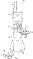
- Fig. 1 illustrates an exemplary emulsification surgical console, generally designated 100.
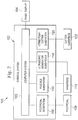
- Fig. 2 is a block diagram of the console 100 showing various subsystems that operate to perform a phacoemulsification procedure.
- the console 100 includes a base housing 102 with a computer system 103 and an associated display screen 104 showing data relating to system operation and performance during a phacoemulsification surgical procedure.
- the console 100 also includes at least a part of a number of subsystems that are used together to perform an emulsification surgical procedure. Some of these subsystems include components or elements that are separable from or not disposed on the console 100.
- the subsystems include a foot pedal subsystem 106 that includes, for example, a foot pedal 108, a fluidics subsystem 110 including a hand piece 112 with an integrated aspiration and irrigation pump, an ultrasonic generator subsystem 116 that provides an ultrasonic oscillation to a cutting needle of the hand piece 112, and a pneumatic vitrectomy cutter subsystem 120 including a vitrectomy hand piece 122 (not shown in Fig. 1 ).
- a foot pedal subsystem 106 that includes, for example, a foot pedal 108
- a fluidics subsystem 110 including a hand piece 112 with an integrated aspiration and irrigation pump
- an ultrasonic generator subsystem 116 that provides an ultrasonic oscillation to a cutting needle of the hand piece 112
- a pneumatic vitrectomy cutter subsystem 120 including a vitrectomy hand piece 122 (not shown in Fig. 1 ).
- Fig. 3 is a block diagram schematically illustrating a part of the fluidics subsystem 110 according to an exemplary embodiment.
- the fluidics subsystem 110 includes an irrigation system 335, an aspiration system 365, and the hand piece 112.
- hand piece 112 comprises a graspable body 305 having a distal end denoted by number 310 and a proximal end denoted by number 315.
- a cutting tip 320 and an irrigation sleeve 325 extend from the distal end 310 and are in fluid communication with a surgical site, such as an eye during a phacoemulsification procedure.
- a surgical site such as an eye during a phacoemulsification procedure.
- the hand piece 112 includes portions of the irrigation system 335 and portions of the aspiration system 365.
- the hand piece 112 includes a pump 360 and a sensor 392 associated with the aspiration system 365.
- the sensor 392 may be located along the aspiration path 375 or located near the distal end 310 and in fluid communication with the surgical site.
- the sensor 392 may be located within the surgical site and in communication with a controller forming a part of the fluidics subsystem 110, as described below.
- the sensor 392 detects a pressure at the surgical site or a pressure associated with the surgical site.
- the hand piece 112 also includes an aspiration valve 390, which is shown associated with the aspiration system 365.
- the irrigation system 335 includes an irrigation conduit 340 that forms an irrigation path 345 that is in fluid communication with the sleeve 325 and an irrigation fluid supply 350.
- Irrigation fluid 355 flows from the irrigation fluid supply 350, through the irrigation conduit 340 and through the sleeve 325 into the surgical site.
- the irrigation fluid supply 350 may be located, for example, on an intravenous pole at a fixed or adjustable height or otherwise disposed about the system.
- the irrigation conduit 340 and the irrigation fluid supply 350 are not in contact with the base housing 102, therefore active irrigation is eliminated.
- the irrigation conduit 340 may be a flexible tubing.
- the pump 360 interfaces with the flexible irrigation conduit 340.
- the irrigation system 335 includes an optional irrigation sensor 342 that may be used to detect fluid characteristics of the irrigation fluid in the irrigation conduit 340.
- the optional irrigation sensor 342 is located along the irrigation path 345 between the driver 400 and the distal end 310. In another embodiment (not shown), the optional irrigation sensor 342 is located along the irrigation path 345 between the driver 400 and the proximal end 315.
- the optional irrigation sensor 342 is a pressure transducer configured to detect pressure within the irrigation conduit 340. The pressure transducer may be configured to detect pressure upstream from the pump 360 and the detected pressure may be correlated to a flow rate.
- the detected pressure may be correlated to a flow rate or may be correlated to pressure within the surgical site or may be correlated to IOP.
- the optional irrigation sensor 342 is a flow sensor that directly measures flow in the irrigation conduit 340.
- the aspiration system 365 includes an aspiration conduit 370 that forms an aspiration path 375 that is in fluid communication with the tip 320 and a drain reservoir 380.
- the aspiration conduit 370 is a flexible tubing.
- Aspiration fluid 385 flows away from the surgical site, through the tip 320 and collects in the drain reservoir 380.
- the aspiration system 365 also comprises the aspiration valve 390.
- the aspiration valve 390 is a variable controlled valve.
- the aspiration valve 390 is a peizotronic valve. In the embodiment shown, the aspiration valve 390 is located between the pump 360 and the proximal end 315.
- Aspiration fluid 385 generally comprises irrigation fluid 355 that has been in contact with the surgical site, and other matter, such as an eye lens, that is to be removed from the surgical site.
- the pump 360 simultaneously interfaces with both the irrigation conduit 340 and the aspiration conduit 370.
- the pump 360 comprises a motor 395 and a driver 400.
- the pump 360 is a peristaltic pump.
- the driver 400 has a spiral structure that presses against the flexible aspiration conduit 370 and the flexible irrigation conduit 340. In this manner, a screw-type or scroll-type aspiration pump is implemented with the motor 395, the driver 400, the aspiration conduit 370, and the irrigation conduit 340.
- the irrigation conduit 340 is disposed so that the movement of the driver 400 causes the irrigation fluid 355 to flow away from the irrigation fluid supply 350 and towards the surgical site while it simultaneously causes the aspiration fluid 385 to flow away from the surgical site and towards the drain reservoir 380.
- the motor 395 is coupled to the driver 400 and serves to rotate the driver 400.
- the motor 395 can be controlled to control the movement of the driver 400 as more clearly described below.
- the motor 395 is typically a DC motor but can be any type of motor or driver suitable for rotating the driver 400. While the pump 360 is described as a screw-type peristaltic pump, other types of pumps may also be used.
- the fluidics subsystem 110 may also include a controller 405.
- the controller 405 is disposed on the console 100.
- the controller 405 is in communication with the sensor 392 and the optional irrigation sensor 342 and is configured to receive IOP information from the sensor 392 or the optional irrigation sensor 342 or both.
- the controller 405 may include a processor and memory that may include an executable program for operating the aspiration valve 390, for operating the pump 360, and or detecting information received from the sensors 392, 342.
- the controller 405 may receive inputs from an operator or may include pre-stored optimum targets for the irrigation flow or the aspiration flow or both. These target and received inputs may be a single value or a range of values.
- the controller 405 is a PID controller configured to control the aspiration valve 390 to mitigate pressure deviations.
- the controller 405 may include one or more pre-established optimum flow thresholds establishing desired fluid flow in the aspiration conduit 370, or the irrigation conduit 340, or both.
- the controller 405 may include an optimum irrigation flow threshold that is a function of an irrigation pressure or irrigation fluid flow rate.
- the controller 405 may include an optimum aspiration flow threshold that is a function of an aspiration pressure or aspiration fluid flow rate. Similar thresholds may be included for a pressure setting and a vacuum setting. These thresholds may be input by an operator or may be preset and stored during manufacturing.
- the controller 405 is in communication with the pump 360 and is configured to control the operation of the pump 360.
- the motor 395 rotates the driver 400.
- the controller 405 controls the operation of the motor 395.
- the driver 400 may be rotated at any desired speed to produce any desired aspiration flow and irrigation flow.
- the driver 400 draws the aspiration fluid 385 through the aspiration conduit 370, and draws the irrigation fluid 355 through the irrigation conduit 340 towards the surgical site.
- the controller 405 uses the pressure information received from the sensor 392 or the optional irrigation sensor 342 or both to determine whether the speed of the pump 360 should be increased or decreased to maintain or regulate IOP.
- the controller 405 is in communication with the aspiration valve 390 and is configured to control the state of the aspiration valve 390, meaning the controller controls the valve to move to a more open position, a fully open position, a more closed position, or fully closed position.
- the flow of the aspiration fluid 385 is controlled by the state of the aspiration valve 390. The more open the aspiration valve 390, the higher the flow of the aspiration fluid 385 within the aspiration conduit 370. The less open the aspiration valve 390, the lower the flow of the aspiration fluid 385 within the aspiration conduit 370.
- the controller 405 uses the pressure or flow information received from the sensor 392 to determine whether the state of the aspiration valve 390 should be adjusted (increased or decreased).
- the controller 405 may be configured to control the IOP using any of a plurality of different or overlapping methods. Some embodiments employ the pump 360 in the hand piece to maintain a desired pressure or a desired flow to the eye. In one embodiment, the controller 405 is configured to maintain IOP by operating the pump at pre-established speed settings that correspond to particular flow rates through the irrigation conduit 340. Accordingly, to increase or decrease the flow rates to a desired target flow rate, the controller 405 controls the pump speed. In other embodiments, the controller 405 receives detected information from the optional irrigation sensor 342, and based on this information, the controller 405 is a responsive system that increases or decreases the pump speed to achieve the desired flow rate.
- valve 390 in the hand piece to maintain a desired pressure or a desired flow to the eye.
- the controller 405 may control the valve 390 to increase or decrease the flow through the aspiration conduit 370.
- the controller 405 operates the valve 390 to maintain aspiration fluid flow within a desired or target flow rate. This may be done by detecting a pressure or the flow rate in the aspiration conduit 370 with the sensor 392, and controlling the valve 390 to increase or decrease the flow rate through the valve 390.
- the controller 405 operates the valve 390 based on valve position, where the flow rate is known based on the position on the valve 390. Accordingly for any given flow rate, the system may maintain the flow rate within a target range by setting the valve to a state that corresponds with the desired flow rate.
- Yet other embodiments employ both the pump 360 and the valve 390 to achieve the desired flow rates, and likewise, the corresponding desired IOP. For example, a faster response may be achieved by simultaneously controlling both the pump speed and the valve state to increase or decrease flow in a manner to maintain a desired IOP.
- the body 305 includes an opening configured to receive a removable hand piece cartridge 406.
- the removable cartridge 406 comprises a portion of the irrigation system 335 and the aspiration system 365, with the portions of the irrigation system 335 and aspiration systems 365 being in fluid communication with the tip 320 and the sleeve 325.
- the use of a removable hand piece cartridge 406 eliminates the need for fluidic cassettes that are generally attached to or within the base housing 102 of the console 100.
- the removable cartridge 406 may be snapped into place to selectively engage with the pump.
- the removable cartridge is for a one-time use.
- the length of aspiration conduit and irrigation conduit between the pump 360 and the surgical site is minimal (on the order of inches or centimeters).
- this length of aspiration conduit and irrigation conduit between the pump and the surgical site may be non-compliant (i.e., it can be rigid). This is represented in Fig. 3 by the length of conduit 407. Having a small length of non-compliant conduit 407 between the pump 360 and the surgical site may relieve post-occlusion surge associated with prior art systems.
- the cross-sectional areas of the irrigation and aspiration conduits 340, 370 may be selected to provide a desired flow rate.
- a cross sectional area of the irrigation conduit 340 and a cross sectional area of the aspiration conduit 370 are the same.
- the cross-sectional areas are different.
- the cross sectional area of the irrigation conduit 340 may be larger than the cross sectional area of the aspiration conduit 370 in order to achieve an irrigation fluid flow that is greater than the aspiration fluid flow, thereby ensuring that the irrigation fluid flow is greater than the aspiration fluid flow. Due to the irrigation conduit 340 and aspiration conduit 370 both interfacing with the driver 400 of the motor 395, differing the cross sectional areas allows for the same driver rotation to produce a variety of irrigation fluid flow to aspiration fluid flow ratios.
- the pressure sensor 392 is located along the aspiration path 375 between the pump 360 and the distal end 310. In this manner, the sensor 392 can accurately read the pressure conditions in the aspiration conduit 370 very close to the surgical site. Detecting pressure conditions close to the surgical site results in early detection of occlusion breaks, and therefore, allowing for early response to prevention of occlusion surges. In some embodiments (not shown), the pressure sensor 392 is located along the aspiration path 375 between the pump 360 and the proximal end 315.
- the irrigation system 335 includes an optional shunt line and irrigation valve 396 (shown in dashed lines), which may be a variable controlled valve.
- the valve is a peizotronic valve.
- the valve 396 may be used to bleed irrigation fluid downstream from the pump to the aspiration line downstream of the aspiration valve 390.
- the valve 396 also may be controlled by the controller and may be adjusted to affect fluid flow through the irrigation line. For example, the valve 396 may be opened to permit fluid flow to continue through the irrigation line when the aspiration valve is closed to affect IOP. This may also reduce the likelihood of an IOP spike when the aspiration valve 390 is controlled.
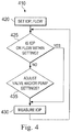
- Fig. 4 illustrates an exemplary method of operating the fluidics subsystem 110.
- the method is generally referred to by the reference number 410.
- the fluidics subsystem 110 may detect pressure deviations in the system, such as those that may occur as a result of an occlusion surge, and may quickly act to counter the effects of the occlusion surge.
- the fluidics subsystem 110 may use the information from the sensor 392 to detect clogged tips due to changes in pressure, as an indicator of the IOP in the eye.
- aspiration and irrigation flows can be adjusted using the pump 360 and the aspiration valve 390, to reduce the effects of a post-occlusion surge.
- the continuous detection of the IOP information by the sensor 392 may result in a more consistent and predictable phacoemulsification procedure by reducing the effects of pressure deviations that occur with post-occlusion surges. That is, by immediately responding to the deviations in pressure.
- the surgeon sets a target IOP on the console and/or a desired flow.
- the controller 405 activates the pump 360 to cause the irrigation fluid 355 to flow through the irrigation conduit 340 and the aspiration fluid 385 to flow through the aspiration conduit 370.
- the controller 405 receives information from the aspiration sensor 392 and determines whether the IOP is at the set IOP of within a range of the set IOP. From this, the system may calculate, or may also directly measure, the flow. If the IOP is within the desired range, the system continues to measure IOP as indicated at step 430. It should be noted that the optimum irrigation flow may be either a specific target value or may be a range of values. If the IOP is outside the desired range, then the system adjusts the pump valve setting to alter the flow at a step 435, thereby directly influencing the IOP. The pump valve adjustment may be done to either increase the flow or to decrease the flow based on the measurement taken. In some embodiments, the system also adjusts the setting on the optional irrigation valve 396 to permit at least a portion of the irrigation fluid to bypass the IOP to reduce the likelihood of an IOP spike.
- the pump In conventional phacoemulsification systems, the pump is located within the base housing 102.
- a relatively long length of flexible conduit (six feet or more) is located between an aspiration and irrigation pump and the eye.
- This relatively long length of flexible conduit has a lot of compliance - it can stretch in response to changes in vacuum pressure. This compliance can result in surges as previously described.
- the system disclosed herein, with the hand piece pump 360 that drives both the irrigation and the aspiration may decrease conduit compliance, decrease pump control delay times, may decrease irrigation resistance to flow, and/or may decrease other delays that might result from using a pressure transducer far down stream in a fluidics cassette. Additionally, because the pump 360 interfaces with the irrigation conduit 340 and causes the irrigation fluid 385 to flow through the irrigation path 375, active irrigation or the pumping of irrigation fluid from the base housing 102, is no longer needed. In addition, some components are eliminated or replaced by this system, such as a fluidics cassette and an active irrigation system.
- a single-use, removable hand piece cartridge of the hand piece 112 may replace the fluidics cassette which, in conventional systems, is temporarily placed in the base housing 102.
- the irrigation conduit may be directly connected from the hand piece 112 to the irrigation fluid supply 350, which can be located at a fixed bottle height.
Claims (6)
- Système d'aspiration et d'irrigation pour irriguer l'oeil et aspirer un fluide à partir de l'oeil pendant une chirurgie oculaire, comprenant:une pièce à main de phacoémulsification (112) comprenant un corps saisissable (305) présentant une extrémité distale et une extrémité proximale;un conduit d'aspiration (370) configuré de manière à transporter un fluide d'aspiration (385) à l'écart d'un site chirurgical;un conduit d'irrigation (340) configuré de manière à transport un fluide d'irrigation en direction du site chirurgical;une pompe (360) disposée à l'intérieur de la pièce à main, dans lequel au moins une partie de la pompe interface avec le conduit d'aspiration et le conduit d'irrigation, de telle sorte que lors de l'activation de la pompe, le fluide d'irrigation à l'intérieur du conduit d'irrigation s'écoule dans une direction vers le site chirurgical, et le fluide d'aspiration à l'intérieur du conduit d'aspiration s'écoule dans une direction à l'écart du site chirurgical;une soupape d'aspiration (390) disposée à l'intérieur de la pièce à main dans le conduit d'aspiration (370) entre la pompe (360) et un réservoir de drainage (380), la soupape d'aspiration étant configurée de manière à commander un débit de fluide d'aspiration à l'intérieur du conduit d'aspiration; etun capteur de pression (392) pour détecter une pression d'aspiration au niveau ou le long du conduit d'aspiration; etun dispositif de commande (405) en communication avec la pompe (360), la soupape d'aspiration (390) et le capteur de pression (392),dans lequel le dispositif de commande est configuré de manière à commander le fonctionnement de la pompe et de la soupape sur la base d'informations en en provenance du capteur.
- Système selon la revendication 1, dans lequel le dispositif de commande (405) est configuré de manière à modifier la pression intraoculaire (PIO) en réglant la vitesse de la pompe (360) ou en réglant l'état de la soupape (390), ou les deux.
- Système selon la revendication 1, dans lequel le capteur de pression (392) est situé à l'intérieur de la pièce à main le long du conduit d'aspiration (370).
- Système selon la revendication 1, dans lequel le conduit d'irrigation (340) présente une première aire de section transversale, et le conduit d'aspiration (370) présente une seconde aire de section transversale, et la première aire de section transversale est plus grande que la seconde aire de section transversale.
- Système selon la revendication 1, dans lequel la pièce à main comprend en outre une cartouche amovible (406) qui est disposée dans le corps et qui comprend au moins une partie du conduit d'aspiration et au moins une partie du conduit d'irrigation.
- Système selon la revendication 1, comprenant une seconde soupape de commande (396) pour commander un écoulement à travers une ligne qui relie le ligne d'irrigation à la ligne d'aspiration.
Applications Claiming Priority (2)
| Application Number | Priority Date | Filing Date | Title |
|---|---|---|---|
| US201261735637P | 2012-12-11 | 2012-12-11 | |
| PCT/US2013/064202 WO2014092851A1 (fr) | 2012-12-11 | 2013-10-10 | Pièce à main de phacoémulsification avec pompe d'aspiration et d'irrigation intégrée |
Publications (3)
| Publication Number | Publication Date |
|---|---|
| EP2874583A1 EP2874583A1 (fr) | 2015-05-27 |
| EP2874583A4 EP2874583A4 (fr) | 2015-08-12 |
| EP2874583B1 true EP2874583B1 (fr) | 2017-09-06 |
Family
ID=50881735
Family Applications (1)
| Application Number | Title | Priority Date | Filing Date |
|---|---|---|---|
| EP13863111.4A Active EP2874583B1 (fr) | 2012-12-11 | 2013-10-10 | Pièce à main de phacoémulsification avec pompe d'aspiration et d'irrigation intégrée |
Country Status (8)
| Country | Link |
|---|---|
| US (2) | US9445943B2 (fr) |
| EP (1) | EP2874583B1 (fr) |
| JP (1) | JP6612618B2 (fr) |
| CN (1) | CN104640523B (fr) |
| AU (2) | AU2013360295B2 (fr) |
| CA (1) | CA2882220A1 (fr) |
| ES (1) | ES2642772T3 (fr) |
| WO (1) | WO2014092851A1 (fr) |
Families Citing this family (54)
| Publication number | Priority date | Publication date | Assignee | Title |
|---|---|---|---|---|
| US9433725B2 (en) | 2011-12-23 | 2016-09-06 | Alcon Research, Ltd. | Combined coaxial and bimanual irrigation/aspiration apparatus |
| US9205186B2 (en) | 2013-03-14 | 2015-12-08 | Abbott Medical Optics Inc. | System and method for providing pressurized infusion |
| US9549850B2 (en) * | 2013-04-26 | 2017-01-24 | Novartis Ag | Partial venting system for occlusion surge mitigation |
| KR102240262B1 (ko) | 2013-06-06 | 2021-04-14 | 알콘 인코포레이티드 | 변환기 세척/흡인 장치 |
| US10137034B2 (en) | 2013-11-26 | 2018-11-27 | Novartis Ag | Pressure-sensing vitrectomy surgical systems and methods |
| US20160089268A1 (en) * | 2014-09-30 | 2016-03-31 | Novartis Ag | Phacoemulsification hand piece with integrated venturi aspiration pump |
| US10195316B2 (en) * | 2015-06-17 | 2019-02-05 | Johnson & Johnson Surgical Vision, Inc. | System and method for providing pressurized infusion and increasing operating room efficiency |
| JP2017064165A (ja) * | 2015-09-30 | 2017-04-06 | 株式会社ニデック | 眼科手術装置 |
| US10624785B2 (en) | 2016-01-30 | 2020-04-21 | Carl Zeiss Meditec Cataract Technology Inc. | Devices and methods for ocular surgery |
| US9839749B2 (en) * | 2016-04-27 | 2017-12-12 | Novartis Ag | Intraocular pressure sensing systems, devices, and methods |
| US11051978B2 (en) | 2016-05-10 | 2021-07-06 | Alcon Inc. | Automated aspiration throttling in vitreoretinal surgery |
| WO2017199135A1 (fr) * | 2016-05-17 | 2017-11-23 | Novartis Ag | Régulation automatisée de liquide visqueux en chirurgie vitréo-rétinienne |
| US10702415B2 (en) * | 2016-08-18 | 2020-07-07 | Alcon Inc. | Surgical apparatus including aspiration device sensors |
| US10690127B2 (en) * | 2016-08-30 | 2020-06-23 | Alcon Inc. | Handheld ophthalmic probe with peristaltic pump and associated devices, systems, and methods |
| EP3295906B1 (fr) * | 2016-09-14 | 2021-07-28 | Fritz Ruck Ophthalmologische Systeme GmbH | Système d'exécution d'une phacoémulsification |
| US11179147B2 (en) | 2016-10-14 | 2021-11-23 | Michael Jerome Designs, LLC | Devices for intraocular surgery |
| EP3318291A1 (fr) * | 2016-11-03 | 2018-05-09 | This AG | Gestion de liquide dans un appareil ophtalmologique |
| US11357907B2 (en) | 2017-02-10 | 2022-06-14 | Johnson & Johnson Surgical Vision, Inc. | Apparatus, system, and method of gas infusion to allow for pressure control of irrigation in a surgical system |
| DE102017102829A1 (de) * | 2017-02-13 | 2018-08-16 | Cardiobridge Gmbh | Spülsystem |
| JP6932967B2 (ja) * | 2017-03-29 | 2021-09-08 | 株式会社ニデック | 灌流吸引装置 |
| EP4052685A1 (fr) | 2017-05-04 | 2022-09-07 | Carl Zeiss Meditec Cataract Technology Inc. | Dispositifs de chirurgie oculaire |
| CN107281624A (zh) * | 2017-06-16 | 2017-10-24 | 李建彩 | 一种妇产科护理用移动清洗装置 |
| EP3609420A4 (fr) * | 2017-06-26 | 2020-12-23 | St. Jude Medical, Cardiology Division, Inc. | Cathéter irrigué à flux rétrograde |
| CN107320239B (zh) * | 2017-07-06 | 2019-06-28 | 温州市人民医院 | 角膜异物刮取收集清洗系统 |
| CN110996816B (zh) | 2017-07-25 | 2023-06-30 | 史赛克欧洲运营有限责任公司 | 用于与外科手术系统一起使用的冲洗套管 |
| EP3691585B1 (fr) * | 2017-10-04 | 2023-09-27 | Johnson & Johnson Surgical Vision, Inc. | Systèmes de mesure de débit de fluide dans un système à base de venturi |
| US11071816B2 (en) | 2017-10-04 | 2021-07-27 | Johnson & Johnson Surgical Vision, Inc. | System, apparatus and method for monitoring anterior chamber intraoperative intraocular pressure |
| EP3691707B1 (fr) | 2017-10-04 | 2021-11-17 | Johnson & Johnson Surgical Vision, Inc. | Système pour augmenter la pression d'irrigation et pour maintenir la pio lors d'un afflux post-occlusion |
| US20190099547A1 (en) * | 2017-10-04 | 2019-04-04 | Abbott Medical Optics Inc. | System, Apparatus and Method for Maintaining Anterior Chamber Intraoperative Intraocular Pressure |
| NL2019887B1 (en) * | 2017-11-10 | 2019-05-17 | Crea Ip B V | Method and system for active irrigation of an ophthalmic surgical site |
| CN107874910A (zh) * | 2017-11-28 | 2018-04-06 | 熊文华 | 一种超声波碎化乳化耳道清洗治疗装置及方法 |
| US11154421B2 (en) | 2018-04-20 | 2021-10-26 | Johnson & Johnson Surgical Vision, Inc. | System and method for providing pressurized infusion transfer reservoirs |
| AU2019282173A1 (en) * | 2018-06-05 | 2020-12-10 | Carl Zeiss Meditec Cataract Technology Inc. | Ophthalmic microsurgical tools, systems, and methods of use |
| CN108670547B (zh) * | 2018-06-07 | 2020-12-04 | 河源光明眼科医院有限公司 | 白内障手术装置 |
| WO2020068823A1 (fr) * | 2018-09-24 | 2020-04-02 | Stryker Corporation | Systèmes et méthodes pour améliorer la réactivité de contrôle durant l'aspiration |
| CN111281648B (zh) * | 2018-12-08 | 2022-01-21 | 李聪 | 一种超声乳化治疗仪 |
| KR20210124298A (ko) | 2019-02-01 | 2021-10-14 | 칼 짜이스 메디텍 캐터랙트 테크놀로지 인크. | 일체형 흡인 펌프를 갖는 안과 절단 기구 |
| JP2022532255A (ja) | 2019-05-17 | 2022-07-13 | カール・ツァイス・メディテック・キャタラクト・テクノロジー・インコーポレイテッド | 一体化吸引ポンプを有する眼科用切削器具 |
| KR20220032046A (ko) | 2019-06-07 | 2022-03-15 | 칼 짜이스 메디텍 캐터랙트 테크놀로지 인크. | 안과 절단 도구용 다중 스테이지 트리거 |
| CN110338970B (zh) | 2019-07-23 | 2024-02-02 | 以诺康医疗科技(苏州)有限公司 | 带传感器的超声乳化手柄及浪涌控制系统、方法 |
| AU2020362986A1 (en) * | 2019-10-08 | 2022-03-17 | Alcon Inc. | Aspiration systems and methods with multiple pumps and pressure sensor |
| DE102019216669A1 (de) * | 2019-10-29 | 2021-04-29 | Carl Zeiss Meditec Ag | Ophthalmochirurgische Einrichtung |
| US20210146019A1 (en) * | 2019-11-20 | 2021-05-20 | Johnson & Johnson Surgical Vision, Inc. | Vane pump for medical instrument |
| US20220008251A1 (en) * | 2020-07-13 | 2022-01-13 | Johnson & Johnson Surgical Vision, Inc. | Aspiration bypass control in a phacoemulsification probe |
| US20220133537A1 (en) | 2020-11-05 | 2022-05-05 | Johnson & Johnson Surgical Vision, Inc. | Controlling intraocular pressure during phacoemulsification procedures |
| US20220192876A1 (en) * | 2020-12-22 | 2022-06-23 | Johnson & Johnson Surgical Vision, Inc. | Module for aspiration and irrigation control |
| US20220192878A1 (en) * | 2020-12-22 | 2022-06-23 | Johnson & Johnson Surgical Vision, Inc. | Processor-controlled pump in irrigation line of phacoemulsification probe |
| US20220193322A1 (en) * | 2020-12-22 | 2022-06-23 | Johnson & Johnson Surgical Vision, Inc. | Proximal bypass channel |
| WO2022211012A1 (fr) * | 2021-03-31 | 2022-10-06 | 東レ株式会社 | Système de régulation de température in vivo |
| US11771818B2 (en) | 2021-04-26 | 2023-10-03 | Johnson & Johnson Surgical Vision, Inc. | Fluid dynamics control |
| US11771594B2 (en) | 2021-04-26 | 2023-10-03 | Johnson & Johnson Surgical Vision, Inc. | Controlling intraocular pressure during phacoemulsification procedure |
| US11679194B2 (en) | 2021-04-27 | 2023-06-20 | Contego Medical, Inc. | Thrombus aspiration system and methods for controlling blood loss |
| WO2022263951A1 (fr) * | 2021-06-15 | 2022-12-22 | Johnson & Johnson Surgical Vision, Inc. | Irrigation améliorée dans un système de phacoémulsification |
| US20230028279A1 (en) * | 2021-07-26 | 2023-01-26 | Johnson & Johnson Surgical Vision, Inc. | Progressive cavity pump cartridge with infrared temperature sensors on fluid inlet and outlet |
Family Cites Families (274)
| Publication number | Priority date | Publication date | Assignee | Title |
|---|---|---|---|---|
| US351159A (en) | 1886-10-19 | Jacob bbengel | ||
| US294334A (en) | 1884-02-26 | loetzee | ||
| US865631A (en) | 1906-11-26 | 1907-09-10 | Frank P Cotter | Check-valve. |
| US1061142A (en) | 1909-10-21 | 1913-05-06 | Nikola Tesla | Fluid propulsion |
| US1121697A (en) | 1914-08-27 | 1914-12-22 | John Weil | Puzzle. |
| GB369037A (en) | 1931-04-22 | 1932-03-17 | Yoshinobu Wada | Improvements in or relating to a pumping apparatus for medical treatments |
| US2121936A (en) | 1934-05-01 | 1938-06-28 | Phillips Petroleum Co | Combination excess flow and check valve |
| US2015123A (en) | 1934-05-11 | 1935-09-24 | Pennell Samuel | Blood transfusion apparatus |
| US2386765A (en) | 1944-04-18 | 1945-10-16 | E A R Inc | Internal-combustion engine charge forming device |
| US2623725A (en) | 1946-10-30 | 1952-12-30 | Asa D Sands | Safety valve |
| US2536836A (en) | 1947-05-05 | 1951-01-02 | Leonard C Bowling | Valve |
| US2755816A (en) | 1949-05-07 | 1956-07-24 | Collins Valve Company Inc | Check valves |
| US2987004A (en) | 1955-07-29 | 1961-06-06 | Jerome L Murray | Fluid pressure device |
| US3085589A (en) | 1960-06-06 | 1963-04-16 | Asa D Sands | Safety valve |
| US3191807A (en) | 1961-11-13 | 1965-06-29 | Microchemical Specialties Co | Dispenser adapted for ultra-micro range |
| US3336942A (en) | 1964-07-28 | 1967-08-22 | Garland B Keith | Check valve |
| US3447478A (en) | 1967-03-03 | 1969-06-03 | Miles Lab | Peristaltic pump |
| NL145136C (fr) | 1967-07-25 | 1900-01-01 | ||
| US3487784A (en) | 1967-10-26 | 1970-01-06 | Edson Howard Rafferty | Pumps capable of use as heart pumps |
| US3561471A (en) | 1968-10-29 | 1971-02-09 | Asa D Sands | Safety valve |
| US3567345A (en) | 1969-02-10 | 1971-03-02 | Shamban & Co W S | Peristaltic pump |
| US3996935A (en) | 1969-02-14 | 1976-12-14 | Surgical Design Corporation | Surgical-type method for removing material |
| BE758029A (fr) | 1969-10-27 | 1971-04-26 | Rhone Poulenc Sa | Pompe peristaltique |
| US3882872A (en) | 1970-01-05 | 1975-05-13 | Nicholas G Douvas | Method and apparatus for cataract surgery |
| FR2102904A5 (fr) | 1970-08-28 | 1972-04-07 | Logeais Labor Jacques | |
| US3693613A (en) | 1970-12-09 | 1972-09-26 | Cavitron Corp | Surgical handpiece and flow control system for use therewith |
| US3756270A (en) | 1972-04-25 | 1973-09-04 | Monocar Hc Internacional Sa | Auxiliary anti pollution air intake device for internal combustion engines |
| US3818913A (en) | 1972-08-30 | 1974-06-25 | M Wallach | Surgical apparatus for removal of tissue |
| US3930505A (en) | 1974-06-24 | 1976-01-06 | Hydro Pulse Corporation | Surgical apparatus for removal of tissue |
| US4205948A (en) | 1977-02-10 | 1980-06-03 | Jones Allan R | Peristaltic pump |
| US4140118A (en) | 1977-03-09 | 1979-02-20 | Andros Incorporated | Cassette chamber for intravenous delivery system |
| US4187057A (en) | 1978-01-11 | 1980-02-05 | Stewart-Naumann Laboratories, Inc. | Peristaltic infusion pump and disposable cassette for use therewith |
| GB2029514A (en) | 1978-08-31 | 1980-03-19 | Charlesworth M | Peristaltic fluid-machines |
| US4255081A (en) | 1979-06-07 | 1981-03-10 | Oklejas Robert A | Centrifugal pump |
| FR2466641A1 (fr) | 1979-09-27 | 1981-04-10 | Boeuf Lola Le | Pompe peristaltique |
| JPS5825614B2 (ja) | 1980-08-31 | 1983-05-28 | 重夫 中島 | 粉粒体圧送方法ならびに同装置 |
| US4392794A (en) | 1980-12-29 | 1983-07-12 | Arthur Foxcroft | Peristaltic pump |
| US4496342A (en) | 1981-03-20 | 1985-01-29 | Surgical Design Corporation | Surge prevention system for an ophthalmic instrument |
| JPS58501474A (ja) | 1981-08-13 | 1983-09-01 | コモンウエルス サイエンテイフイツク アンド インダストリアルリサ−チ オ−ガニゼイシヨン | 往復動ピストン−シリンダ装置 |
| US4417856A (en) | 1981-08-25 | 1983-11-29 | Minissian Kevin G | Peristaltic pump |
| US4493706A (en) | 1982-08-12 | 1985-01-15 | American Hospital Supply Corporation | Linear peristaltic pumping apparatus and disposable casette therefor |
| US4479761A (en) | 1982-12-28 | 1984-10-30 | Baxter Travenol Laboratories, Inc. | Actuator apparatus for a prepackaged fluid processing module having pump and valve elements operable in response to externally applied pressures |
| US4537561A (en) | 1983-02-24 | 1985-08-27 | Medical Technology, Ltd. | Peristaltic infusion pump and disposable cassette for use therewith |
| JPS59154259U (ja) | 1983-04-01 | 1984-10-16 | 株式会社ウベ循研 | 血液用円錐形送液ポンプ |
| DE3321151C2 (de) | 1983-06-11 | 1986-09-18 | Walter Küsnacht Beck | Vorrichtung zum Absaugen von Sekreten |
| JPS601391A (ja) | 1983-06-17 | 1985-01-07 | Mitsubishi Heavy Ind Ltd | スラリ−ポンプ |
| SE451541B (sv) | 1983-06-30 | 1987-10-19 | Gambro Lundia Ab | System for extrakorporeal blodbehandling |
| US4684328A (en) | 1984-06-28 | 1987-08-04 | Piezo Electric Products, Inc. | Acoustic pump |
| US4657490A (en) | 1985-03-27 | 1987-04-14 | Quest Medical, Inc. | Infusion pump with disposable cassette |
| GB8510382D0 (en) | 1985-04-24 | 1985-05-30 | Russell D | Peristaltic pump |
| DK160633C (da) | 1985-05-15 | 1991-09-02 | Henning Munk Ejlersen | Slangepumpe, isaer til avendelse som insulinpumpe |
| US4713051A (en) | 1985-05-21 | 1987-12-15 | Coopervision, Inc. | Cassette for surgical irrigation and aspiration and sterile package therefor |
| US4935005A (en) | 1985-06-05 | 1990-06-19 | Nestle, S.A. | Opthalmic fluid flow control system |
| CA1280326C (fr) | 1985-09-25 | 1991-02-19 | Leif Joakim Sundblom | Cassette pour aspiration rapide sans tube |
| US4768547A (en) | 1985-11-18 | 1988-09-06 | Critikon, Inc. | Parenteral solution pump assembly |
| US4861332A (en) | 1986-04-14 | 1989-08-29 | Ultramed Corporation | Ultrasonic probe |
| US4909713A (en) | 1986-05-07 | 1990-03-20 | Cobe Laboratories, Inc. | Peristaltic pump |
| US4764165A (en) | 1986-07-17 | 1988-08-16 | Mentor O & O, Inc. | Ophthalmic aspirator-irrigator with valve |
| US4705500A (en) | 1986-07-17 | 1987-11-10 | Mentor O & O, Inc. | Ophthalmic aspirator-irrigator |
| US4854825A (en) | 1987-02-27 | 1989-08-08 | Commonwealth Scientific And Industrial Research Organization | Multi-stage vacuum pump |
| SU1533696A1 (ru) | 1987-04-22 | 1990-01-07 | Предприятие П/Я А-3697 | Перистальтический насос |
| US4798580A (en) | 1987-04-27 | 1989-01-17 | Site Microsurgical Systems, Inc. | Disposable peristaltic pump cassette system |
| US5125891A (en) | 1987-04-27 | 1992-06-30 | Site Microsurgical Systems, Inc. | Disposable vacuum/peristaltic pump cassette system |
| US5195960A (en) | 1987-04-27 | 1993-03-23 | Site Microsurgical Systems, Inc. | Disposable vacuum/peristaltic pump cassette system |
| CA1321522C (fr) | 1987-10-14 | 1993-08-24 | Rickey Paul Davis | Systeme d'irrigation et d'aspiration utilise en chirurgie |
| IT1220167B (it) | 1987-12-18 | 1990-06-06 | Renato Vicentini | Pompa volumetrica per fluidi liquidi o gassosi perfezionata |
| US4904238A (en) | 1987-12-21 | 1990-02-27 | Alcon Laboratories, Inc. | Irrigation/aspiration handpiece |
| DE3809582A1 (de) | 1988-03-22 | 1989-10-12 | Franz Otto Dr Ing Kopp | Peristaltisch arbeitende membranpumpe |
| JPH0270987A (ja) | 1988-09-05 | 1990-03-09 | Terumo Corp | ローラポンプ |
| SU1590649A1 (ru) | 1988-10-27 | 1990-09-07 | Минский Филиал Всесоюзного Научно-Исследовательского И Проектно-Конструкторского Института Механизированного И Ручного Строительно-Монтажного Инструмента, Вибраторов И Строительно-Отделочных Машин | Перистальтический насос |
| US5046486A (en) | 1989-01-13 | 1991-09-10 | Stryker Corporation | Compact pulsing pump for irrigation handpiece |
| FR2644212B1 (fr) | 1989-03-13 | 1991-11-15 | Malbec Edouard | Cassette pour pompe peristaltique a tube deformable, et pompe peristaltique equipee d'une telle cassette |
| US4963131A (en) | 1989-03-16 | 1990-10-16 | Surgin Surgical Instrumentation, Inc. | Disposable cassette for ophthalmic surgery applications |
| US5062775A (en) | 1989-09-29 | 1991-11-05 | Rocky Mountain Research, Inc. | Roller pump in an extra corporeal support system |
| US4909710A (en) | 1989-10-23 | 1990-03-20 | Fisher Scientific Company | Linear peristaltic pump |
| US5041096A (en) | 1989-10-27 | 1991-08-20 | Nestle, S.A. | Fluid handling method and system and fluid interface apparatus usable therewith |
| JPH03164586A (ja) | 1989-11-22 | 1991-07-16 | Fujita Corp | スクイズ式ポンプによる流体圧送方法と、スクイズ式ポンプによる流体圧送装置 |
| US5106367A (en) | 1989-11-28 | 1992-04-21 | Alexander Ureche | Eye surgery apparatus with vacuum surge suppressor |
| US5167620A (en) | 1989-11-28 | 1992-12-01 | Alexandar Ureche | Eye surgery methods |
| US5106366A (en) | 1990-03-08 | 1992-04-21 | Nestle, S.A. | Medical fluid cassette and control system |
| US5038965A (en) | 1990-04-06 | 1991-08-13 | Spruhventile Gmbh | Pump dispenser for delivering a predetermined dosage regardless of method of actuation |
| US6007513A (en) | 1990-07-17 | 1999-12-28 | Aziz Yehia Anis | Removal of tissue |
| US5263830A (en) | 1991-01-23 | 1993-11-23 | Sharp Kabushiki Kaisha | Peristaltic pump assembly |
| EP0518050B1 (fr) | 1991-05-10 | 1996-07-10 | Terumo Kabushiki Kaisha | Pompe à liquide |
| US5316440A (en) | 1991-05-10 | 1994-05-31 | Terumo Kabushiki Kaisha | Blood pump apparatus |
| US5185002A (en) | 1991-06-28 | 1993-02-09 | Alcon Surgical, Inc. | Transducer apparatus having water hammer dampening means |
| US5273517A (en) | 1991-07-09 | 1993-12-28 | Haemonetics Corporation | Blood processing method and apparatus with disposable cassette |
| US5207647A (en) | 1991-11-05 | 1993-05-04 | Phelps David Y | Needle device |
| US5267956A (en) | 1992-02-05 | 1993-12-07 | Alcon Surgical, Inc. | Surgical cassette |
| US5242404A (en) | 1992-02-12 | 1993-09-07 | American Cyanamid Company | Aspiration control system |
| FR2690622B1 (fr) | 1992-04-29 | 1995-01-20 | Chronotec | Système de pompe à perfusion ambulatoire programmable. |
| FR2690715B1 (fr) | 1992-04-30 | 1994-07-22 | Debiotech Sa | Pompe peristaltique a cassette munie d'un ensemble de detrompage. |
| US5302093A (en) | 1992-05-01 | 1994-04-12 | Mcgaw, Inc. | Disposable cassette with negative head height fluid supply and method |
| US5554013A (en) | 1992-05-01 | 1996-09-10 | Mcgaw, Inc. | Disposable cassette with negative head height fluid supply |
| US5308673A (en) | 1992-05-07 | 1994-05-03 | Minnesota Mining And Manufacturing Company | Stitchbonded absorbent articles and method of making same |
| AU673364B2 (en) | 1992-06-03 | 1996-11-07 | Abbott Medical Optics Inc. | Pressure transducer interface |
| EP0643570B1 (fr) | 1992-06-03 | 1998-08-12 | Allergan, Inc. | Systeme de gestion de tubulures |
| US5342181A (en) | 1992-06-15 | 1994-08-30 | Datascope Investment Corp. | Single roller blood pump and pump/oxygenator system using same |
| US5257917A (en) | 1992-10-02 | 1993-11-02 | Cole-Parmer Instrument Company | Peristaltic pump having means for reducing flow pulsation |
| US5437678A (en) | 1992-11-30 | 1995-08-01 | Neomedix Corporation | Ophthalmic lens removal method and apparatus |
| GB2273533B (en) | 1992-12-18 | 1996-09-25 | Minnesota Mining & Mfg | Pumping cassette with integral manifold |
| US5403277A (en) | 1993-01-12 | 1995-04-04 | Minnesota Mining And Manufacturing Company | Irrigation system with tubing cassette |
| US5350357A (en) | 1993-03-03 | 1994-09-27 | Deka Products Limited Partnership | Peritoneal dialysis systems employing a liquid distribution and pumping cassette that emulates gravity flow |
| US6746419B1 (en) | 1993-04-19 | 2004-06-08 | Stryker Corporation | Irrigation handpiece with built in pulsing pump |
| ATE168260T1 (de) | 1993-05-07 | 1998-08-15 | Grieshaber & Co Ag | Augenchirurgische einrichtung zum zerkleinern und entfernen des linsenkerns aus dem auge eines lebewesens |
| US5868678A (en) | 1993-06-30 | 1999-02-09 | Medex, Inc. | Two-part medical pressure transducer with diaphragm stand-offs |
| US5462416A (en) | 1993-12-22 | 1995-10-31 | Baxter International Inc. | Peristaltic pump tube cassette for blood processing systems |
| US5484239A (en) | 1993-12-22 | 1996-01-16 | Baxter International Inc. | Peristaltic pump and valve assembly for fluid processing systems |
| CA2155735A1 (fr) | 1993-12-22 | 1995-06-29 | Richard C. Giesler | Chambre de goutte-a-goutte a amorcage automatique offrant une visibilite amelioree |
| US5514069A (en) | 1993-12-22 | 1996-05-07 | Baxter International Inc. | Stress-bearing umbilicus for a compact centrifuge |
| US5746708A (en) | 1993-12-22 | 1998-05-05 | Baxter International Inc. | Peristaltic pump tube holder with pump tube shield and cover |
| GB2285837B (en) | 1994-01-24 | 1998-05-13 | Varian Australia | Peristaltic pump |
| US5443370A (en) | 1994-05-02 | 1995-08-22 | Wang; Ro-Pin | Two cylinder manual air pump |
| US5460490A (en) | 1994-05-19 | 1995-10-24 | Linvatec Corporation | Multi-purpose irrigation/aspiration pump system |
| US5515930A (en) | 1994-06-01 | 1996-05-14 | Glendo Corporation | Handheld pneumatic power tool apparatus |
| JP3679143B2 (ja) | 1994-06-30 | 2005-08-03 | 株式会社ニデック | 灌流吸引装置 |
| US5533976A (en) | 1994-07-15 | 1996-07-09 | Allergan, Inc. | Reusable cartridge assembly for a phaco machine |
| US5575632A (en) | 1994-09-12 | 1996-11-19 | Ivac Medical Systems, Inc. | Engineered pumping segment |
| US5476448A (en) | 1994-10-19 | 1995-12-19 | Urich; Alex | Apparatus for suppressing a vacuum surge in eye surgery |
| US5573506A (en) | 1994-11-25 | 1996-11-12 | Block Medical, Inc. | Remotely programmable infusion system |
| US5542918A (en) | 1995-01-06 | 1996-08-06 | Zimmer, Inc. | Vacuum driven fluid pump for an aspiration/irrigation instrument |
| NL9500442A (nl) | 1995-03-06 | 1996-10-01 | Elu Ijmond Techniek B V | Slangepomp. |
| US5910110A (en) * | 1995-06-07 | 1999-06-08 | Mentor Ophthalmics, Inc. | Controlling pressure in the eye during surgery |
| DE19529668A1 (de) | 1995-08-11 | 1997-02-13 | Kaltenbach & Voigt | Ärztliches oder zahnärztliches Turbinen-Handstück |
| US5630711A (en) | 1995-09-08 | 1997-05-20 | Graymills Corporation | Peristaltic pump having a loop-shaped tube path |
| US5712543A (en) | 1995-10-31 | 1998-01-27 | Smith & Nephew Endoscopy Inc. | Magnetic switching element for controlling a surgical device |
| US5588815A (en) | 1995-11-15 | 1996-12-31 | Alcon Laboratories, Inc. | Surgical cassette loading and unloading system |
| US5705018A (en) | 1995-12-13 | 1998-01-06 | Hartley; Frank T. | Micromachined peristaltic pump |
| US5759017A (en) | 1996-01-31 | 1998-06-02 | Medtronic Electromedics, Inc. | Peristaltic pump and tube loading system |
| US5688112A (en) | 1996-02-22 | 1997-11-18 | Garay; Thomas William | Rotor axis aligned tube and outlet for a peristaltic pump system |
| US5827218A (en) | 1996-04-18 | 1998-10-27 | Stryker Corporation | Surgical suction pool tip |
| US5788667A (en) | 1996-07-19 | 1998-08-04 | Stoller; Glenn | Fluid jet vitrectomy device and method for use |
| US5853386A (en) | 1996-07-25 | 1998-12-29 | Alaris Medical Systems, Inc. | Infusion device with disposable elements |
| AUPO178796A0 (en) * | 1996-08-22 | 1996-09-12 | Oversby Pty Ltd | Intraocular irrigation/aspiration device |
| FR2753235B1 (fr) | 1996-09-10 | 1998-12-04 | Conseilray Sa | Pompe peristaltique portable |
| US5733256A (en) | 1996-09-26 | 1998-03-31 | Micro Medical Devices | Integrated phacoemulsification system |
| US5746719A (en) | 1996-10-25 | 1998-05-05 | Arthur D. Little, Inc. | Fluid flow control system incorporating a disposable pump cartridge |
| US6129699A (en) | 1997-10-31 | 2000-10-10 | Sorenson Development, Inc. | Portable persistaltic pump for peritoneal dialysis |
| JP3106980B2 (ja) | 1996-11-07 | 2000-11-06 | 富士電機株式会社 | 液体定量供給ポンプ |
| US5899915A (en) | 1996-12-02 | 1999-05-04 | Angiotrax, Inc. | Apparatus and method for intraoperatively performing surgery |
| JP2995548B2 (ja) | 1997-03-06 | 1999-12-27 | ジャパンフォ−カス株式会社 | 高吸引圧による手術に利用できる角膜虚脱防止装置 |
| US5879363A (en) | 1997-03-18 | 1999-03-09 | Circuit Tree Medical, Inc. | Disposable surgical ultrasonic transducer |
| DE19711675A1 (de) | 1997-03-20 | 1998-10-01 | Fraunhofer Ges Forschung | Chirurgisches Handinstrument |
| US5897524A (en) | 1997-03-24 | 1999-04-27 | Wortrich; Theodore S. | Compact cassette for ophthalmic surgery |
| US6371934B1 (en) | 1997-08-06 | 2002-04-16 | C. R. Bard, Inc. | Irrigation system and tip with debrider |
| US6099494A (en) | 1997-08-20 | 2000-08-08 | Stryker Corporation | Pulsed irrigator useful for surgical and medical procedures |
| US6270326B1 (en) | 1997-08-29 | 2001-08-07 | Seiko Epson Corporation | Transfusion device and liquid supply tube |
| CN1110292C (zh) * | 1997-10-16 | 2003-06-04 | 北京中科电气高技术公司 | 白内障超声乳化仪 |
| US5972012A (en) | 1997-10-17 | 1999-10-26 | Angiotrax, Inc. | Cutting apparatus having articulable tip |
| US6012999A (en) | 1997-12-24 | 2000-01-11 | Patterson; Richard A. | Hydraulically-operated bicycle shifting system with positive pressure actuation |
| WO1999038549A1 (fr) | 1998-01-28 | 1999-08-05 | Mentor Corporation | Systeme de tubes permettant de maintenir une pression de fluide en chirurgie |
| US5997499A (en) | 1998-06-04 | 1999-12-07 | Alcon Laboratories, Inc. | Tip for a liquefaction handpiece |
| US6080128A (en) | 1998-06-04 | 2000-06-27 | Alcon Laboratories, Inc. | Liquefaction handpiece |
| US5989212A (en) | 1998-06-04 | 1999-11-23 | Alcon Laboratories, Inc. | Pumping chamber for a liquefaction handpiece having a countersink electrode |
| US6179805B1 (en) | 1998-06-04 | 2001-01-30 | Alcon Laboratories, Inc. | Liquefracture handpiece |
| US5927956A (en) | 1998-09-01 | 1999-07-27 | Linvatec Corporation | Peristaltic pump tubing system with latching cassette |
| US6214017B1 (en) | 1998-09-25 | 2001-04-10 | Sherwood Services Ag | Ultrasonic surgical apparatus |
| US6605054B2 (en) | 1998-09-30 | 2003-08-12 | Advanced Medical Optics | Multiple bypass port phaco tip |
| DE19856744C2 (de) | 1998-12-09 | 2003-06-26 | Plasmaselect Ag | Pumpschlauchsystem zur peristaltischen Förderung von flüssigen oder gasförmigen Medien |
| US6058779A (en) | 1999-02-10 | 2000-05-09 | Cole; Mark S. | Coupled diaphragm interface for phacoemulsification apparatus |
| US6241700B1 (en) | 1999-03-08 | 2001-06-05 | Alcon Laboratories, Inc. | Surgical handpiece |
| US6689146B1 (en) | 1999-04-29 | 2004-02-10 | Stryker Corporation | Powered surgical handpiece with integrated irrigator and suction application |
| AU770310B2 (en) | 1999-05-12 | 2004-02-19 | Dia Medical A/S | Peristaltic fluid pump |
| US6179808B1 (en) | 1999-06-18 | 2001-01-30 | Alcon Laboratories, Inc. | Method of controlling the operating parameters of a surgical system |
| MXPA01011676A (es) | 1999-06-18 | 2003-09-10 | Alcon Mfg Ltd | Sistema de control de infusion. |
| US6604908B1 (en) | 1999-07-20 | 2003-08-12 | Deka Products Limited Partnership | Methods and systems for pulsed delivery of fluids from a pump |
| US6416293B1 (en) | 1999-07-20 | 2002-07-09 | Deka Products Limited Partnership | Pumping cartridge including a bypass valve and method for directing flow in a pumping cartridge |
| DE19936959A1 (de) | 1999-08-05 | 2001-02-15 | Wolf Gmbh Richard | Quetschventil für medizinische Instrumente und Geräte |
| US20040253129A1 (en) | 1999-08-31 | 2004-12-16 | Sorensen Gary P. | Liquid venting surgical cassette |
| US6293926B1 (en) | 1999-11-10 | 2001-09-25 | Alcon Universal Ltd. | Peristaltic pump and cassette |
| US6962488B2 (en) | 1999-11-10 | 2005-11-08 | Alcon, Inc. | Surgical cassette having an aspiration pressure sensor |
| US20010016706A1 (en) | 1999-08-31 | 2001-08-23 | Kurt D. Leukanech | Peristaltic pump |
| US6261283B1 (en) | 1999-08-31 | 2001-07-17 | Alcon Universal Ltd. | Liquid venting surgical system and cassette |
| US6497680B1 (en) | 1999-12-17 | 2002-12-24 | Abbott Laboratories | Method for compensating for pressure differences across valves in cassette type IV pump |
| JP3529311B2 (ja) | 1999-12-22 | 2004-05-24 | 眞人 岸本 | 眼内手術装置 |
| US6296460B1 (en) | 2000-03-01 | 2001-10-02 | Steve C. Smith | Rotary cavity pump |
| GB0012931D0 (en) | 2000-05-26 | 2000-07-19 | Constance Ltd | Fluid bags |
| GB0012930D0 (en) | 2000-05-26 | 2000-07-19 | Constance Ltd | Peristaltic pumps |
| US6432078B1 (en) * | 2000-06-19 | 2002-08-13 | Gholam A. Peyman | System and method for removing cataract or other cells in an eye using water jet and suction |
| DE10034711B4 (de) | 2000-07-17 | 2006-04-20 | Fresenius Medical Care Deutschland Gmbh | Dichtvorrichtung |
| US20030153872A9 (en) | 2000-09-22 | 2003-08-14 | Tanner Howard M. C. | Apparatus and method for micro-volume infusion |
| EP1258260A3 (fr) | 2000-10-04 | 2003-11-26 | Terumo Kabushiki Kaisha | Appareil de dialyse péritonéale |
| US6527765B2 (en) | 2000-10-06 | 2003-03-04 | Charles D. Kelman | Cryogenic surgical system and method of use in removal of tissue |
| JP4752079B2 (ja) | 2001-02-26 | 2011-08-17 | 株式会社ミクロン | 歯科用バキュームハンドピース |
| WO2002077456A2 (fr) | 2001-03-21 | 2002-10-03 | Innovent, Llc. | Pompes peristaltiques inversees et procedes associes |
| US6958058B1 (en) | 2001-05-18 | 2005-10-25 | Medsafe Inc. | Methods and devices for pumping fluid and performing surgical procedures |
| US6890291B2 (en) | 2001-06-25 | 2005-05-10 | Mission Medical, Inc. | Integrated automatic blood collection and processing unit |
| ITRM20010669A1 (it) | 2001-11-09 | 2003-05-09 | Optikon 2000 Spa | Cassetta infusione aspirazione (i/a) con sistema di aspirazione sia mediante pompa peristaltica o comunque volumetrica che mediante pompa pr |
| US6599277B2 (en) | 2001-11-30 | 2003-07-29 | Bausch & Lomb Incorporated | Aspiration flow meter and control |
| DE10202378B4 (de) | 2002-01-23 | 2005-07-21 | Dürr Dental GmbH & Co. KG | Dentales Behandlungsgerät |
| JP2005518875A (ja) | 2002-02-28 | 2005-06-30 | セイ ファミリー トラスト | 携帯可能な電池作動式吸入器 |
| DE10209495C1 (de) | 2002-03-05 | 2003-10-30 | Wefis Vision Gmbh | Chirurgisches Instrument, insbesondere Phaco-Hohlnadel |
| US7087036B2 (en) | 2002-05-24 | 2006-08-08 | Baxter International Inc. | Fail safe system for operating medical fluid valves |
| US7238164B2 (en) | 2002-07-19 | 2007-07-03 | Baxter International Inc. | Systems, methods and apparatuses for pumping cassette-based therapies |
| DE10246469A1 (de) | 2002-10-04 | 2004-04-15 | Applica Gmbh | Pumpvorrichtung |
| DE10251598A1 (de) | 2002-11-06 | 2004-05-19 | A.M.I. Agency For Medical Innovations Gmbh | Medizinisches Spül- und Sauggerät |
| US7150607B2 (en) | 2002-11-18 | 2006-12-19 | International Remote Imaging Systems, Inc. | Uniform flow displacement pump |
| RU2241887C1 (ru) | 2003-02-28 | 2004-12-10 | Авилкин Юрий Михайлович | Клапанный узел насоса |
| US7645127B2 (en) | 2003-04-29 | 2010-01-12 | Loren Hagen | Pulseless peristaltic pump |
| WO2004110524A2 (fr) | 2003-06-06 | 2004-12-23 | Phacor, Inc. | Cassette d'ecoulement de fluide pour instrument de chirurgie ophtalmique |
| WO2005009511A2 (fr) | 2003-07-31 | 2005-02-03 | Debiotech S.A. | Systeme de conduite de dialyse peritoneale |
| US20050049539A1 (en) | 2003-09-03 | 2005-03-03 | O'hara Gerald P. | Control system for driving fluids through an extracorporeal blood circuit |
| US7445436B2 (en) | 2003-09-29 | 2008-11-04 | Bausch & Lomb Incorporated | Peristaltic pump with a moveable pump head |
| US7168930B2 (en) | 2003-09-29 | 2007-01-30 | Bausch & Lomb Incorporated | Peristaltic pump with air venting via the movement of a pump head or a backing plate during surgery |
| US7604607B2 (en) | 2003-09-29 | 2009-10-20 | Bausch & Lomb Incorporated | Peristaltic pump fitment for attachment to an aspirant collection bag |
| US7461968B2 (en) | 2003-10-30 | 2008-12-09 | Deka Products Limited Partnership | System, device, and method for mixing liquids |
| US7776006B2 (en) | 2003-11-05 | 2010-08-17 | Baxter International Inc. | Medical fluid pumping system having real time volume determination |
| US7273359B2 (en) | 2003-11-05 | 2007-09-25 | Linvatec Corporation | Peristaltic irrigation pump system |
| US8038639B2 (en) | 2004-11-04 | 2011-10-18 | Baxter International Inc. | Medical fluid system with flexible sheeting disposable unit |
| US7276060B2 (en) | 2004-02-26 | 2007-10-02 | Alcon, Inc. | Surgical handpiece tip |
| US7959608B2 (en) | 2004-04-27 | 2011-06-14 | The Spectranetics Corporation | Thrombectomy and soft debris removal device |
| US20050271531A1 (en) | 2004-06-03 | 2005-12-08 | Brown William R Jr | Oral care device |
| US20060000925A1 (en) | 2004-06-30 | 2006-01-05 | Maher Colin G | Reduced sized micro-fluid jet nozzle structure |
| US8591464B2 (en) | 2004-08-27 | 2013-11-26 | Atul Kumar | Low turbulence fluid management system for endoscopic procedures |
| US8252321B2 (en) | 2004-09-13 | 2012-08-28 | Chrono Therapeutics, Inc. | Biosynchronous transdermal drug delivery for longevity, anti-aging, fatigue management, obesity, weight loss, weight management, delivery of nutraceuticals, and the treatment of hyperglycemia, alzheimer's disease, sleep disorders, parkinson's disease, aids, epilepsy, attention deficit disorder, nicotine addiction, cancer, headache and pain control, asthma, angina, hypertension, depression, cold, flu and the like |
| US20060074345A1 (en) | 2004-09-29 | 2006-04-06 | Hibner John A | Biopsy apparatus and method |
| WO2006121698A2 (fr) | 2005-05-05 | 2006-11-16 | Dial Discoveries, Inc. | Procedes et systemes permettant de deplacer des fluides biologicques incorporant des systemes d'impulseur a disques empiles |
| CN1299657C (zh) * | 2005-06-02 | 2007-02-14 | 上海交通大学 | 白内障超声乳化仪 |
| JP5128471B2 (ja) | 2005-06-13 | 2013-01-23 | スミス アンド ネフュー インコーポレーテッド | 外科手術用流体の管理 |
| US7648465B2 (en) | 2005-06-28 | 2010-01-19 | Alcon, Inc. | Method of testing a surgical system |
| US8353297B2 (en) | 2005-08-31 | 2013-01-15 | Novartis Ag | Pulse manipulation for controlling a phacoemulsification surgical system |
| US20070135760A1 (en) | 2005-12-14 | 2007-06-14 | Williams David L | Occlusion clearance in microsurgical system |
| US8500421B2 (en) | 2005-12-31 | 2013-08-06 | Novartis Ag | System and method operable to prevent tubing displacement within a peristaltic pump |
| US7775780B2 (en) | 2006-01-24 | 2010-08-17 | Alcon, Inc. | Surgical cassette |
| US20070217919A1 (en) | 2006-03-14 | 2007-09-20 | Alcon, Inc. | Peristaltic pump |
| NL2000032C2 (nl) | 2006-03-20 | 2007-09-21 | Bredel Hose Pumps B V | Peristaltische pomp, werkwijze voor het vervaardigen van een slang daarvoor, en slang voor een dergelijke pomp. |
| US7862540B2 (en) | 2006-05-17 | 2011-01-04 | Alcon Research, Ltd. | Ophthalmic injection device using shape memory alloy |
| US8303542B2 (en) | 2006-06-10 | 2012-11-06 | Bausch & Lomb Incorporated | Ophthalmic surgical cassette and system |
| US8480625B2 (en) | 2006-10-23 | 2013-07-09 | Bausch & Lamb Incorporated | Grooved aspiration pump roller-head assembly |
| CA2672376C (fr) | 2006-10-30 | 2012-03-20 | Gambro Lundia Ab | Dispositif d'hemo(dia)filtration |
| US9033940B2 (en) | 2006-11-09 | 2015-05-19 | Abbott Medical Optics Inc. | Eye treatment system with fluidics pump interface |
| US7967777B2 (en) | 2006-11-09 | 2011-06-28 | Abbott Medical Optics Inc. | Eye treatment system with multiple pumps |
| US8414534B2 (en) | 2006-11-09 | 2013-04-09 | Abbott Medical Optics Inc. | Holding tank devices, systems, and methods for surgical fluidics cassette |
| US9295765B2 (en) | 2006-11-09 | 2016-03-29 | Abbott Medical Optics Inc. | Surgical fluidics cassette supporting multiple pumps |
| US10959881B2 (en) | 2006-11-09 | 2021-03-30 | Johnson & Johnson Surgical Vision, Inc. | Fluidics cassette for ocular surgical system |
| US8491528B2 (en) | 2006-11-09 | 2013-07-23 | Abbott Medical Optics Inc. | Critical alignment of fluidics cassettes |
| US20100286791A1 (en) | 2006-11-21 | 2010-11-11 | Goldsmith David S | Integrated system for the ballistic and nonballistic infixion and retrieval of implants |
| US7695242B2 (en) | 2006-12-05 | 2010-04-13 | Fuller Howard J | Wind turbine for generation of electric power |
| US8579929B2 (en) | 2006-12-08 | 2013-11-12 | Alcon Research, Ltd. | Torsional ultrasound hand piece that eliminates chatter |
| CN200991440Y (zh) | 2006-12-29 | 2007-12-19 | 武汉半边天医疗技术发展有限公司 | 一种囊肿抽吸泵 |
| EP1970081A1 (fr) | 2007-03-12 | 2008-09-17 | Jean-Denis Rochat | Unité de pompage de nutrition entérale ou parentérale ou de perfusion |
| US20080247892A1 (en) | 2007-04-03 | 2008-10-09 | Seiko Epson Corporation | Liquid transfer device and suction unit |
| ES2400538T3 (es) | 2007-04-20 | 2013-04-10 | Doheny Eye Institute | Centro quirúrgico independiente |
| US7540855B2 (en) | 2007-06-01 | 2009-06-02 | Peregrine Surgical, Ltd. | Disposable aspirator cassette |
| WO2008157674A1 (fr) | 2007-06-19 | 2008-12-24 | Yablon, Jay, R. | Système de suppression d'affaissement de la chambre suite à une occlusion pour un appareil chirurgical et procédé d'utilisation |
| US7901376B2 (en) | 2007-07-05 | 2011-03-08 | Baxter International Inc. | Dialysis cassette having multiple outlet valve |
| US8162633B2 (en) | 2007-08-02 | 2012-04-24 | Abbott Medical Optics Inc. | Volumetric fluidics pump with translating shaft path |
| WO2009029666A1 (fr) | 2007-08-27 | 2009-03-05 | Quest Medical, Inc. | Pompe sanguine à deux chambres |
| DE102007044790A1 (de) | 2007-09-19 | 2009-04-02 | Dieter Mann | Einhandgerät für die Augenchirurgie |
| US7892332B2 (en) | 2007-10-01 | 2011-02-22 | Baxter International Inc. | Dialysis systems having air traps with internal structures to enhance air removal |
| US20090149802A1 (en) | 2007-12-07 | 2009-06-11 | Ross Peter Jones | Surgical System Including a Trap for Noise-Inducing Materials |
| AU2009219172B2 (en) | 2008-02-27 | 2014-11-27 | Smith & Nephew, Inc. | Peristaltic pumping apparatus and method |
| US20090246035A1 (en) | 2008-03-28 | 2009-10-01 | Smiths Medical Asd, Inc. | Pump Module Fluidically Isolated Displacement Device |
| US8449495B2 (en) | 2008-05-28 | 2013-05-28 | Baxter Healthcare Inc. | Dialysis system having automated effluent sampling and peritoneal equilibration test |
| DE102008026916A1 (de) | 2008-06-05 | 2009-12-17 | Fresenius Medical Care Deutschland Gmbh | Organizer zum lösbaren Aufnehmen von Komponenten von Blutschlauchsätzen und Verfahren zum Herstellen sowie zum Vorbereiten desselben |
| US8523539B2 (en) | 2008-06-19 | 2013-09-03 | The Board Of Regents Of The University Of Texas Systems | Centrifugal pump |
| US9005157B2 (en) | 2008-11-07 | 2015-04-14 | Abbott Medical Optics Inc. | Surgical cassette apparatus |
| EP3175831B1 (fr) | 2008-11-07 | 2018-12-26 | Johnson & Johnson Surgical Vision, Inc. | Commutation automatique de différents niveaux d'aspiration et/ou pompes à une sonde oculaire |
| US8998864B2 (en) | 2008-11-14 | 2015-04-07 | Bausch & Lomb Incorporated | Ophthalmic surgical cassettes for ophthalmic surgery |
| US9044544B2 (en) | 2008-11-21 | 2015-06-02 | Baxter International Inc. | Dialysis machine having auto-connection system with roller occluder |
| US20110238029A1 (en) | 2008-11-28 | 2011-09-29 | Terumo Kabushiki Kaisha | Blood bag system and cassette |
| CA2750407C (fr) | 2009-01-07 | 2018-12-04 | Enlighten Technologies, Inc. | Dispositifs d'enlevement de tissu |
| JP5806208B2 (ja) | 2009-05-06 | 2015-11-10 | アルコン リサーチ, リミテッド | 複数のセグメントを有する蠕動ポンプおよびカセット |
| US8281898B2 (en) | 2009-06-11 | 2012-10-09 | Medtronic Xomed, Inc. | Lubrication and exhaust system for a powered surgical instrument |
| US20110137231A1 (en) | 2009-12-08 | 2011-06-09 | Alcon Research, Ltd. | Phacoemulsification Hand Piece With Integrated Aspiration Pump |
| US20110144567A1 (en) * | 2009-12-15 | 2011-06-16 | Alcon Research, Ltd. | Phacoemulsification Hand Piece With Integrated Aspiration Pump and Cartridge |
| US8366420B1 (en) | 2010-01-27 | 2013-02-05 | Geschwender Robert C | Linear peristaltic pump having opposing staggered curved surfaces |
| US20110184374A1 (en) | 2010-01-27 | 2011-07-28 | Gao Shawn X | Peristaltic Pump and Cassette |
| EP2365220B1 (fr) | 2010-03-03 | 2017-08-23 | Kongsberg Automotive AB | Pompe linéaire |
| US8632589B2 (en) | 2010-05-04 | 2014-01-21 | Abbott Medical Optics Inc. | IOL insertion system with semi-automatic trailing haptic configuration management |
| US20110313343A1 (en) | 2010-06-18 | 2011-12-22 | Alcon Research, Ltd. | Phacoemulsification Fluidics System Having a Single Pump Head |
| US8784357B2 (en) | 2010-09-15 | 2014-07-22 | Alcon Research, Ltd. | Phacoemulsification hand piece with two independent transducers |
| NL2005425C2 (nl) | 2010-09-30 | 2012-04-02 | Nijhuis Pompen B V | Pompinrichting. |
| EP2625425A2 (fr) | 2010-10-07 | 2013-08-14 | Vanderbilt University | Micropompe péristaltique et systèmes et procédés associés |
-
2013
- 2013-10-10 WO PCT/US2013/064202 patent/WO2014092851A1/fr active Application Filing
- 2013-10-10 ES ES13863111.4T patent/ES2642772T3/es active Active
- 2013-10-10 CA CA2882220A patent/CA2882220A1/fr not_active Abandoned
- 2013-10-10 EP EP13863111.4A patent/EP2874583B1/fr active Active
- 2013-10-10 JP JP2015546461A patent/JP6612618B2/ja active Active
- 2013-10-10 US US14/050,428 patent/US9445943B2/en active Active
- 2013-10-10 CN CN201380048803.8A patent/CN104640523B/zh not_active Expired - Fee Related
- 2013-10-10 AU AU2013360295A patent/AU2013360295B2/en not_active Ceased
-
2016
- 2016-08-17 US US15/239,409 patent/US10182940B2/en active Active
-
2017
- 2017-10-12 AU AU2017245367A patent/AU2017245367A1/en not_active Abandoned
Non-Patent Citations (1)
| Title |
|---|
| None * |
Also Published As
| Publication number | Publication date |
|---|---|
| ES2642772T3 (es) | 2017-11-20 |
| JP2015536758A (ja) | 2015-12-24 |
| CA2882220A1 (fr) | 2014-06-19 |
| EP2874583A4 (fr) | 2015-08-12 |
| US20160354243A1 (en) | 2016-12-08 |
| EP2874583A1 (fr) | 2015-05-27 |
| WO2014092851A1 (fr) | 2014-06-19 |
| US20140163455A1 (en) | 2014-06-12 |
| US10182940B2 (en) | 2019-01-22 |
| AU2013360295B2 (en) | 2017-07-27 |
| AU2013360295A1 (en) | 2015-03-05 |
| CN104640523B (zh) | 2017-07-04 |
| JP6612618B2 (ja) | 2019-11-27 |
| US9445943B2 (en) | 2016-09-20 |
| AU2017245367A1 (en) | 2017-11-02 |
| CN104640523A (zh) | 2015-05-20 |
Similar Documents
| Publication | Publication Date | Title |
|---|---|---|
| US10182940B2 (en) | Phacoemulsification hand piece with integrated aspiration and irrigation pump | |
| US10314953B2 (en) | Partial venting system for occlusion surge mitigation | |
| US20180049921A1 (en) | Phacoemulsification hand piece with integrated aspiration pump | |
| US9314553B2 (en) | Surgical system | |
| US20110144567A1 (en) | Phacoemulsification Hand Piece With Integrated Aspiration Pump and Cartridge | |
| US20170367885A1 (en) | Phacoemulsification handpiece with flexible impeller pump |
Legal Events
| Date | Code | Title | Description |
|---|---|---|---|
| PUAI | Public reference made under article 153(3) epc to a published international application that has entered the european phase |
Free format text: ORIGINAL CODE: 0009012 |
|
| 17P | Request for examination filed |
Effective date: 20150217 |
|
| AK | Designated contracting states |
Kind code of ref document: A1 Designated state(s): AL AT BE BG CH CY CZ DE DK EE ES FI FR GB GR HR HU IE IS IT LI LT LU LV MC MK MT NL NO PL PT RO RS SE SI SK SM TR |
|
| AX | Request for extension of the european patent |
Extension state: BA ME |
|
| RA4 | Supplementary search report drawn up and despatched (corrected) |
Effective date: 20150714 |
|
| RIC1 | Information provided on ipc code assigned before grant |
Ipc: A61F 9/007 20060101AFI20150708BHEP Ipc: A61M 1/00 20060101ALI20150708BHEP |
|
| DAX | Request for extension of the european patent (deleted) | ||
| 17Q | First examination report despatched |
Effective date: 20161116 |
|
| GRAP | Despatch of communication of intention to grant a patent |
Free format text: ORIGINAL CODE: EPIDOSNIGR1 |
|
| INTG | Intention to grant announced |
Effective date: 20170512 |
|
| GRAS | Grant fee paid |
Free format text: ORIGINAL CODE: EPIDOSNIGR3 |
|
| GRAA | (expected) grant |
Free format text: ORIGINAL CODE: 0009210 |
|
| AK | Designated contracting states |
Kind code of ref document: B1 Designated state(s): AL AT BE BG CH CY CZ DE DK EE ES FI FR GB GR HR HU IE IS IT LI LT LU LV MC MK MT NL NO PL PT RO RS SE SI SK SM TR |
|
| REG | Reference to a national code |
Ref country code: GB Ref legal event code: FG4D |
|
| REG | Reference to a national code |
Ref country code: CH Ref legal event code: EP Ref country code: AT Ref legal event code: REF Ref document number: 925068 Country of ref document: AT Kind code of ref document: T Effective date: 20170915 |
|
| REG | Reference to a national code |
Ref country code: FR Ref legal event code: PLFP Year of fee payment: 5 |
|
| REG | Reference to a national code |
Ref country code: IE Ref legal event code: FG4D |
|
| REG | Reference to a national code |
Ref country code: DE Ref legal event code: R096 Ref document number: 602013026407 Country of ref document: DE |
|
| REG | Reference to a national code |
Ref country code: ES Ref legal event code: FG2A Ref document number: 2642772 Country of ref document: ES Kind code of ref document: T3 Effective date: 20171120 |
|
| REG | Reference to a national code |
Ref country code: NL Ref legal event code: MP Effective date: 20170906 |
|
| REG | Reference to a national code |
Ref country code: LT Ref legal event code: MG4D |
|
| PG25 | Lapsed in a contracting state [announced via postgrant information from national office to epo] |
Ref country code: SE Free format text: LAPSE BECAUSE OF FAILURE TO SUBMIT A TRANSLATION OF THE DESCRIPTION OR TO PAY THE FEE WITHIN THE PRESCRIBED TIME-LIMIT Effective date: 20170906 Ref country code: FI Free format text: LAPSE BECAUSE OF FAILURE TO SUBMIT A TRANSLATION OF THE DESCRIPTION OR TO PAY THE FEE WITHIN THE PRESCRIBED TIME-LIMIT Effective date: 20170906 Ref country code: LT Free format text: LAPSE BECAUSE OF FAILURE TO SUBMIT A TRANSLATION OF THE DESCRIPTION OR TO PAY THE FEE WITHIN THE PRESCRIBED TIME-LIMIT Effective date: 20170906 Ref country code: NO Free format text: LAPSE BECAUSE OF FAILURE TO SUBMIT A TRANSLATION OF THE DESCRIPTION OR TO PAY THE FEE WITHIN THE PRESCRIBED TIME-LIMIT Effective date: 20171206 Ref country code: HR Free format text: LAPSE BECAUSE OF FAILURE TO SUBMIT A TRANSLATION OF THE DESCRIPTION OR TO PAY THE FEE WITHIN THE PRESCRIBED TIME-LIMIT Effective date: 20170906 |
|
| REG | Reference to a national code |
Ref country code: AT Ref legal event code: MK05 Ref document number: 925068 Country of ref document: AT Kind code of ref document: T Effective date: 20170906 |
|
| PG25 | Lapsed in a contracting state [announced via postgrant information from national office to epo] |
Ref country code: RS Free format text: LAPSE BECAUSE OF FAILURE TO SUBMIT A TRANSLATION OF THE DESCRIPTION OR TO PAY THE FEE WITHIN THE PRESCRIBED TIME-LIMIT Effective date: 20170906 Ref country code: LV Free format text: LAPSE BECAUSE OF FAILURE TO SUBMIT A TRANSLATION OF THE DESCRIPTION OR TO PAY THE FEE WITHIN THE PRESCRIBED TIME-LIMIT Effective date: 20170906 Ref country code: GR Free format text: LAPSE BECAUSE OF FAILURE TO SUBMIT A TRANSLATION OF THE DESCRIPTION OR TO PAY THE FEE WITHIN THE PRESCRIBED TIME-LIMIT Effective date: 20171207 Ref country code: BG Free format text: LAPSE BECAUSE OF FAILURE TO SUBMIT A TRANSLATION OF THE DESCRIPTION OR TO PAY THE FEE WITHIN THE PRESCRIBED TIME-LIMIT Effective date: 20171206 |
|
| PG25 | Lapsed in a contracting state [announced via postgrant information from national office to epo] |
Ref country code: NL Free format text: LAPSE BECAUSE OF FAILURE TO SUBMIT A TRANSLATION OF THE DESCRIPTION OR TO PAY THE FEE WITHIN THE PRESCRIBED TIME-LIMIT Effective date: 20170906 |
|
| PG25 | Lapsed in a contracting state [announced via postgrant information from national office to epo] |
Ref country code: CZ Free format text: LAPSE BECAUSE OF FAILURE TO SUBMIT A TRANSLATION OF THE DESCRIPTION OR TO PAY THE FEE WITHIN THE PRESCRIBED TIME-LIMIT Effective date: 20170906 Ref country code: RO Free format text: LAPSE BECAUSE OF FAILURE TO SUBMIT A TRANSLATION OF THE DESCRIPTION OR TO PAY THE FEE WITHIN THE PRESCRIBED TIME-LIMIT Effective date: 20170906 Ref country code: PL Free format text: LAPSE BECAUSE OF FAILURE TO SUBMIT A TRANSLATION OF THE DESCRIPTION OR TO PAY THE FEE WITHIN THE PRESCRIBED TIME-LIMIT Effective date: 20170906 |
|
| PG25 | Lapsed in a contracting state [announced via postgrant information from national office to epo] |
Ref country code: SM Free format text: LAPSE BECAUSE OF FAILURE TO SUBMIT A TRANSLATION OF THE DESCRIPTION OR TO PAY THE FEE WITHIN THE PRESCRIBED TIME-LIMIT Effective date: 20170906 Ref country code: IS Free format text: LAPSE BECAUSE OF FAILURE TO SUBMIT A TRANSLATION OF THE DESCRIPTION OR TO PAY THE FEE WITHIN THE PRESCRIBED TIME-LIMIT Effective date: 20180106 Ref country code: AT Free format text: LAPSE BECAUSE OF FAILURE TO SUBMIT A TRANSLATION OF THE DESCRIPTION OR TO PAY THE FEE WITHIN THE PRESCRIBED TIME-LIMIT Effective date: 20170906 Ref country code: SK Free format text: LAPSE BECAUSE OF FAILURE TO SUBMIT A TRANSLATION OF THE DESCRIPTION OR TO PAY THE FEE WITHIN THE PRESCRIBED TIME-LIMIT Effective date: 20170906 Ref country code: EE Free format text: LAPSE BECAUSE OF FAILURE TO SUBMIT A TRANSLATION OF THE DESCRIPTION OR TO PAY THE FEE WITHIN THE PRESCRIBED TIME-LIMIT Effective date: 20170906 |
|
| REG | Reference to a national code |
Ref country code: CH Ref legal event code: PL |
|
| REG | Reference to a national code |
Ref country code: DE Ref legal event code: R097 Ref document number: 602013026407 Country of ref document: DE |
|
| PG25 | Lapsed in a contracting state [announced via postgrant information from national office to epo] |
Ref country code: MC Free format text: LAPSE BECAUSE OF FAILURE TO SUBMIT A TRANSLATION OF THE DESCRIPTION OR TO PAY THE FEE WITHIN THE PRESCRIBED TIME-LIMIT Effective date: 20170906 |
|
| PLBE | No opposition filed within time limit |
Free format text: ORIGINAL CODE: 0009261 |
|
| STAA | Information on the status of an ep patent application or granted ep patent |
Free format text: STATUS: NO OPPOSITION FILED WITHIN TIME LIMIT |
|
| REG | Reference to a national code |
Ref country code: IE Ref legal event code: MM4A |
|
| PG25 | Lapsed in a contracting state [announced via postgrant information from national office to epo] |
Ref country code: DK Free format text: LAPSE BECAUSE OF FAILURE TO SUBMIT A TRANSLATION OF THE DESCRIPTION OR TO PAY THE FEE WITHIN THE PRESCRIBED TIME-LIMIT Effective date: 20170906 Ref country code: LI Free format text: LAPSE BECAUSE OF NON-PAYMENT OF DUE FEES Effective date: 20171031 Ref country code: CH Free format text: LAPSE BECAUSE OF NON-PAYMENT OF DUE FEES Effective date: 20171031 Ref country code: LU Free format text: LAPSE BECAUSE OF NON-PAYMENT OF DUE FEES Effective date: 20171010 |
|
| 26N | No opposition filed |
Effective date: 20180607 |
|
| REG | Reference to a national code |
Ref country code: BE Ref legal event code: MM Effective date: 20171031 |
|
| PG25 | Lapsed in a contracting state [announced via postgrant information from national office to epo] |
Ref country code: SI Free format text: LAPSE BECAUSE OF FAILURE TO SUBMIT A TRANSLATION OF THE DESCRIPTION OR TO PAY THE FEE WITHIN THE PRESCRIBED TIME-LIMIT Effective date: 20170906 Ref country code: BE Free format text: LAPSE BECAUSE OF NON-PAYMENT OF DUE FEES Effective date: 20171031 |
|
| PG25 | Lapsed in a contracting state [announced via postgrant information from national office to epo] |
Ref country code: MT Free format text: LAPSE BECAUSE OF NON-PAYMENT OF DUE FEES Effective date: 20171010 |
|
| REG | Reference to a national code |
Ref country code: FR Ref legal event code: PLFP Year of fee payment: 6 |
|
| PG25 | Lapsed in a contracting state [announced via postgrant information from national office to epo] |
Ref country code: IE Free format text: LAPSE BECAUSE OF NON-PAYMENT OF DUE FEES Effective date: 20171010 |
|
| PG25 | Lapsed in a contracting state [announced via postgrant information from national office to epo] |
Ref country code: HU Free format text: LAPSE BECAUSE OF FAILURE TO SUBMIT A TRANSLATION OF THE DESCRIPTION OR TO PAY THE FEE WITHIN THE PRESCRIBED TIME-LIMIT; INVALID AB INITIO Effective date: 20131010 |
|
| PG25 | Lapsed in a contracting state [announced via postgrant information from national office to epo] |
Ref country code: CY Free format text: LAPSE BECAUSE OF FAILURE TO SUBMIT A TRANSLATION OF THE DESCRIPTION OR TO PAY THE FEE WITHIN THE PRESCRIBED TIME-LIMIT Effective date: 20170906 |
|
| PG25 | Lapsed in a contracting state [announced via postgrant information from national office to epo] |
Ref country code: MK Free format text: LAPSE BECAUSE OF FAILURE TO SUBMIT A TRANSLATION OF THE DESCRIPTION OR TO PAY THE FEE WITHIN THE PRESCRIBED TIME-LIMIT Effective date: 20170906 |
|
| REG | Reference to a national code |
Ref country code: GB Ref legal event code: 732E Free format text: REGISTERED BETWEEN 20200109 AND 20200115 |
|
| REG | Reference to a national code |
Ref country code: GB Ref legal event code: 732E Free format text: REGISTERED BETWEEN 20200116 AND 20200122 |
|
| PGFP | Annual fee paid to national office [announced via postgrant information from national office to epo] |
Ref country code: ES Payment date: 20191104 Year of fee payment: 7 Ref country code: IT Payment date: 20191009 Year of fee payment: 7 |
|
| REG | Reference to a national code |
Ref country code: DE Ref legal event code: R081 Ref document number: 602013026407 Country of ref document: DE Owner name: ALCON INC., CH Free format text: FORMER OWNER: ALCON RESEARCH, LTD., FORT WORTH, TEX., US |
|
| PG25 | Lapsed in a contracting state [announced via postgrant information from national office to epo] |
Ref country code: TR Free format text: LAPSE BECAUSE OF FAILURE TO SUBMIT A TRANSLATION OF THE DESCRIPTION OR TO PAY THE FEE WITHIN THE PRESCRIBED TIME-LIMIT Effective date: 20170906 |
|
| REG | Reference to a national code |
Ref country code: ES Ref legal event code: PC2A Owner name: ALCON INC. Effective date: 20200407 |
|
| PG25 | Lapsed in a contracting state [announced via postgrant information from national office to epo] |
Ref country code: PT Free format text: LAPSE BECAUSE OF FAILURE TO SUBMIT A TRANSLATION OF THE DESCRIPTION OR TO PAY THE FEE WITHIN THE PRESCRIBED TIME-LIMIT Effective date: 20170906 |
|
| PG25 | Lapsed in a contracting state [announced via postgrant information from national office to epo] |
Ref country code: AL Free format text: LAPSE BECAUSE OF FAILURE TO SUBMIT A TRANSLATION OF THE DESCRIPTION OR TO PAY THE FEE WITHIN THE PRESCRIBED TIME-LIMIT Effective date: 20170906 |
|
| PG25 | Lapsed in a contracting state [announced via postgrant information from national office to epo] |
Ref country code: IT Free format text: LAPSE BECAUSE OF NON-PAYMENT OF DUE FEES Effective date: 20201010 |
|
| REG | Reference to a national code |
Ref country code: ES Ref legal event code: FD2A Effective date: 20220121 |
|
| PG25 | Lapsed in a contracting state [announced via postgrant information from national office to epo] |
Ref country code: ES Free format text: LAPSE BECAUSE OF NON-PAYMENT OF DUE FEES Effective date: 20201011 |
|
| P01 | Opt-out of the competence of the unified patent court (upc) registered |
Effective date: 20230504 |
|
| PGFP | Annual fee paid to national office [announced via postgrant information from national office to epo] |
Ref country code: GB Payment date: 20230921 Year of fee payment: 11 |
|
| PGFP | Annual fee paid to national office [announced via postgrant information from national office to epo] |
Ref country code: FR Payment date: 20230921 Year of fee payment: 11 |
|
| PGFP | Annual fee paid to national office [announced via postgrant information from national office to epo] |
Ref country code: DE Payment date: 20230919 Year of fee payment: 11 |