EP2874533B1 - Endoskopüberrohr zum einsetzen in natürliche körperöffnungen - Google Patents
Endoskopüberrohr zum einsetzen in natürliche körperöffnungen Download PDFInfo
- Publication number
- EP2874533B1 EP2874533B1 EP13819514.4A EP13819514A EP2874533B1 EP 2874533 B1 EP2874533 B1 EP 2874533B1 EP 13819514 A EP13819514 A EP 13819514A EP 2874533 B1 EP2874533 B1 EP 2874533B1
- Authority
- EP
- European Patent Office
- Prior art keywords
- collar
- overtube
- body member
- tubular member
- hub
- Prior art date
- Legal status (The legal status is an assumption and is not a legal conclusion. Google has not performed a legal analysis and makes no representation as to the accuracy of the status listed.)
- Active
Links
- 238000003780 insertion Methods 0.000 title claims description 5
- 230000037431 insertion Effects 0.000 title claims description 5
- 239000012530 fluid Substances 0.000 claims description 21
- 210000002784 stomach Anatomy 0.000 claims description 5
- 238000004891 communication Methods 0.000 claims description 2
- 229920000126 latex Polymers 0.000 claims description 2
- 239000004816 latex Substances 0.000 claims description 2
- 239000002184 metal Substances 0.000 claims description 2
- 229920001195 polyisoprene Polymers 0.000 claims description 2
- 229920000642 polymer Polymers 0.000 claims 1
- 238000000034 method Methods 0.000 description 9
- 230000008878 coupling Effects 0.000 description 5
- 238000010168 coupling process Methods 0.000 description 5
- 238000005859 coupling reaction Methods 0.000 description 5
- 210000001519 tissue Anatomy 0.000 description 4
- 238000001839 endoscopy Methods 0.000 description 2
- 210000003238 esophagus Anatomy 0.000 description 2
- 238000001125 extrusion Methods 0.000 description 2
- 230000002496 gastric effect Effects 0.000 description 2
- 210000001035 gastrointestinal tract Anatomy 0.000 description 2
- 239000003292 glue Substances 0.000 description 2
- 238000001356 surgical procedure Methods 0.000 description 2
- 238000001574 biopsy Methods 0.000 description 1
- 230000000112 colonic effect Effects 0.000 description 1
- 238000010276 construction Methods 0.000 description 1
- 230000001419 dependent effect Effects 0.000 description 1
- 238000003745 diagnosis Methods 0.000 description 1
- 238000002405 diagnostic procedure Methods 0.000 description 1
- 230000000694 effects Effects 0.000 description 1
- 239000013013 elastic material Substances 0.000 description 1
- 208000014674 injury Diseases 0.000 description 1
- 210000004877 mucosa Anatomy 0.000 description 1
- 239000012858 resilient material Substances 0.000 description 1
- 238000005096 rolling process Methods 0.000 description 1
- 230000001225 therapeutic effect Effects 0.000 description 1
- 238000002627 tracheal intubation Methods 0.000 description 1
- 230000008733 trauma Effects 0.000 description 1
Images


Classifications
-
- A—HUMAN NECESSITIES
- A61—MEDICAL OR VETERINARY SCIENCE; HYGIENE
- A61B—DIAGNOSIS; SURGERY; IDENTIFICATION
- A61B1/00—Instruments for performing medical examinations of the interior of cavities or tubes of the body by visual or photographical inspection, e.g. endoscopes; Illuminating arrangements therefor
- A61B1/273—Instruments for performing medical examinations of the interior of cavities or tubes of the body by visual or photographical inspection, e.g. endoscopes; Illuminating arrangements therefor for the upper alimentary canal, e.g. oesophagoscopes, gastroscopes
-
- A—HUMAN NECESSITIES
- A61—MEDICAL OR VETERINARY SCIENCE; HYGIENE
- A61B—DIAGNOSIS; SURGERY; IDENTIFICATION
- A61B1/00—Instruments for performing medical examinations of the interior of cavities or tubes of the body by visual or photographical inspection, e.g. endoscopes; Illuminating arrangements therefor
- A61B1/00131—Accessories for endoscopes
- A61B1/00135—Oversleeves mounted on the endoscope prior to insertion
-
- A—HUMAN NECESSITIES
- A61—MEDICAL OR VETERINARY SCIENCE; HYGIENE
- A61B—DIAGNOSIS; SURGERY; IDENTIFICATION
- A61B1/00—Instruments for performing medical examinations of the interior of cavities or tubes of the body by visual or photographical inspection, e.g. endoscopes; Illuminating arrangements therefor
- A61B1/00112—Connection or coupling means
- A61B1/00121—Connectors, fasteners and adapters, e.g. on the endoscope handle
- A61B1/00128—Connectors, fasteners and adapters, e.g. on the endoscope handle mechanical, e.g. for tubes or pipes
-
- A—HUMAN NECESSITIES
- A61—MEDICAL OR VETERINARY SCIENCE; HYGIENE
- A61B—DIAGNOSIS; SURGERY; IDENTIFICATION
- A61B1/00—Instruments for performing medical examinations of the interior of cavities or tubes of the body by visual or photographical inspection, e.g. endoscopes; Illuminating arrangements therefor
- A61B1/00131—Accessories for endoscopes
- A61B1/0014—Fastening element for attaching accessories to the outside of an endoscope, e.g. clips, clamps or bands
-
- A—HUMAN NECESSITIES
- A61—MEDICAL OR VETERINARY SCIENCE; HYGIENE
- A61B—DIAGNOSIS; SURGERY; IDENTIFICATION
- A61B1/00—Instruments for performing medical examinations of the interior of cavities or tubes of the body by visual or photographical inspection, e.g. endoscopes; Illuminating arrangements therefor
- A61B1/12—Instruments for performing medical examinations of the interior of cavities or tubes of the body by visual or photographical inspection, e.g. endoscopes; Illuminating arrangements therefor with cooling or rinsing arrangements
-
- A—HUMAN NECESSITIES
- A61—MEDICAL OR VETERINARY SCIENCE; HYGIENE
- A61B—DIAGNOSIS; SURGERY; IDENTIFICATION
- A61B1/00—Instruments for performing medical examinations of the interior of cavities or tubes of the body by visual or photographical inspection, e.g. endoscopes; Illuminating arrangements therefor
- A61B1/273—Instruments for performing medical examinations of the interior of cavities or tubes of the body by visual or photographical inspection, e.g. endoscopes; Illuminating arrangements therefor for the upper alimentary canal, e.g. oesophagoscopes, gastroscopes
- A61B1/2736—Gastroscopes
-
- A—HUMAN NECESSITIES
- A61—MEDICAL OR VETERINARY SCIENCE; HYGIENE
- A61B—DIAGNOSIS; SURGERY; IDENTIFICATION
- A61B17/00—Surgical instruments, devices or methods, e.g. tourniquets
- A61B17/34—Trocars; Puncturing needles
- A61B17/3415—Trocars; Puncturing needles for introducing tubes or catheters, e.g. gastrostomy tubes, drain catheters
-
- A—HUMAN NECESSITIES
- A61—MEDICAL OR VETERINARY SCIENCE; HYGIENE
- A61B—DIAGNOSIS; SURGERY; IDENTIFICATION
- A61B17/00—Surgical instruments, devices or methods, e.g. tourniquets
- A61B17/34—Trocars; Puncturing needles
- A61B17/3417—Details of tips or shafts, e.g. grooves, expandable, bendable; Multiple coaxial sliding cannulas, e.g. for dilating
- A61B17/3421—Cannulas
- A61B17/3439—Cannulas with means for changing the inner diameter of the cannula, e.g. expandable
-
- A—HUMAN NECESSITIES
- A61—MEDICAL OR VETERINARY SCIENCE; HYGIENE
- A61M—DEVICES FOR INTRODUCING MEDIA INTO, OR ONTO, THE BODY; DEVICES FOR TRANSDUCING BODY MEDIA OR FOR TAKING MEDIA FROM THE BODY; DEVICES FOR PRODUCING OR ENDING SLEEP OR STUPOR
- A61M39/00—Tubes, tube connectors, tube couplings, valves, access sites or the like, specially adapted for medical use
- A61M39/02—Access sites
- A61M39/06—Haemostasis valves, i.e. gaskets sealing around a needle, catheter or the like, closing on removal thereof
- A61M39/0613—Haemostasis valves, i.e. gaskets sealing around a needle, catheter or the like, closing on removal thereof with means for adjusting the seal opening or pressure
-
- A—HUMAN NECESSITIES
- A61—MEDICAL OR VETERINARY SCIENCE; HYGIENE
- A61M—DEVICES FOR INTRODUCING MEDIA INTO, OR ONTO, THE BODY; DEVICES FOR TRANSDUCING BODY MEDIA OR FOR TAKING MEDIA FROM THE BODY; DEVICES FOR PRODUCING OR ENDING SLEEP OR STUPOR
- A61M39/00—Tubes, tube connectors, tube couplings, valves, access sites or the like, specially adapted for medical use
- A61M39/22—Valves or arrangement of valves
- A61M39/227—Valves actuated by a secondary fluid, e.g. hydraulically or pneumatically actuated valves
- A61M39/228—Valves actuated by a secondary fluid, e.g. hydraulically or pneumatically actuated valves with a tubular diaphragm constrictable by radial fluid force
-
- A—HUMAN NECESSITIES
- A61—MEDICAL OR VETERINARY SCIENCE; HYGIENE
- A61B—DIAGNOSIS; SURGERY; IDENTIFICATION
- A61B17/00—Surgical instruments, devices or methods, e.g. tourniquets
- A61B17/34—Trocars; Puncturing needles
- A61B17/3462—Trocars; Puncturing needles with means for changing the diameter or the orientation of the entrance port of the cannula, e.g. for use with different-sized instruments, reduction ports, adapter seals
-
- A—HUMAN NECESSITIES
- A61—MEDICAL OR VETERINARY SCIENCE; HYGIENE
- A61B—DIAGNOSIS; SURGERY; IDENTIFICATION
- A61B17/00—Surgical instruments, devices or methods, e.g. tourniquets
- A61B17/34—Trocars; Puncturing needles
- A61B17/3417—Details of tips or shafts, e.g. grooves, expandable, bendable; Multiple coaxial sliding cannulas, e.g. for dilating
- A61B17/3421—Cannulas
- A61B2017/345—Cannulas for introduction into a natural body opening
-
- A—HUMAN NECESSITIES
- A61—MEDICAL OR VETERINARY SCIENCE; HYGIENE
- A61B—DIAGNOSIS; SURGERY; IDENTIFICATION
- A61B17/00—Surgical instruments, devices or methods, e.g. tourniquets
- A61B17/34—Trocars; Puncturing needles
- A61B2017/347—Locking means, e.g. for locking instrument in cannula
-
- A—HUMAN NECESSITIES
- A61—MEDICAL OR VETERINARY SCIENCE; HYGIENE
- A61M—DEVICES FOR INTRODUCING MEDIA INTO, OR ONTO, THE BODY; DEVICES FOR TRANSDUCING BODY MEDIA OR FOR TAKING MEDIA FROM THE BODY; DEVICES FOR PRODUCING OR ENDING SLEEP OR STUPOR
- A61M39/00—Tubes, tube connectors, tube couplings, valves, access sites or the like, specially adapted for medical use
- A61M39/02—Access sites
- A61M39/06—Haemostasis valves, i.e. gaskets sealing around a needle, catheter or the like, closing on removal thereof
- A61M2039/0673—Haemostasis valves, i.e. gaskets sealing around a needle, catheter or the like, closing on removal thereof comprising means actively pressing on the device passing through the seal, e.g. inflatable seals, diaphragms, clamps
-
- F—MECHANICAL ENGINEERING; LIGHTING; HEATING; WEAPONS; BLASTING
- F04—POSITIVE - DISPLACEMENT MACHINES FOR LIQUIDS; PUMPS FOR LIQUIDS OR ELASTIC FLUIDS
- F04C—ROTARY-PISTON, OR OSCILLATING-PISTON, POSITIVE-DISPLACEMENT MACHINES FOR LIQUIDS; ROTARY-PISTON, OR OSCILLATING-PISTON, POSITIVE-DISPLACEMENT PUMPS
- F04C2270/00—Control; Monitoring or safety arrangements
- F04C2270/04—Force
- F04C2270/041—Controlled or regulated
-
- G—PHYSICS
- G02—OPTICS
- G02B—OPTICAL ELEMENTS, SYSTEMS OR APPARATUS
- G02B23/00—Telescopes, e.g. binoculars; Periscopes; Instruments for viewing the inside of hollow bodies; Viewfinders; Optical aiming or sighting devices
- G02B23/24—Instruments or systems for viewing the inside of hollow bodies, e.g. fibrescopes
- G02B23/2476—Non-optical details, e.g. housings, mountings, supports
Definitions
- the present invention relates to surgery. More particularly, the invention relates to an access port for providing secure access through a natural body orifice for an endoscope and related instruments.
- the field of gastrointestinal endoscopy is generally directed to diagnostic and therapeutic techniques to observe, modify and remove tissues located in the digestive tract. Such diagnosis is often performed with an endoscope that is inserted into the mouth of a patient, through the esophagus, and into the stomach. Flexible endoscopic instruments are then advanced through one or more working channels of the endoscope to act on tissues within the stomach.
- the endoscope can be used in conjunction with an overtube.
- An overtube is a tubular device that facilitates endoscopy by providing a conduit through which the endoscope can be advanced.
- the use of the overtube protects the gastrointestinal mucosa from trauma and limits risks of aspiration. This is particularly important where access is required to be maintained for repeated withdrawal and reinsertion of the endoscope during certain procedures, such as foreign body removal, multiple biopsy, or procedures requiring instrument exchange which may occur external the endoscope or require withdrawal of the endoscope.
- a known combination valve and clamping device is provided in US5161773 in which a flexible elastic inner lining is secured in a tubular outer shell having a port for introducing a fluid therebetween.
- a source of pressure such as a hypodermic syringe is used to cause the inner elastic sleeve to collapse and deform internally upon itself to surround and form a seal about a catheter located therein, positioning it within the shell.
- the sleeve is collapsed on itself to prevent leakage of a fluid through the valve mechanism.
- Document EP0564578 discloses a rotatably actuated valve for closure of a catheter lumen to control fluid flow through said catheter lumen when the catheter is inserted thereto.
- the valve comprises two sleeve clamps which can be rotated against each other resulting in a twisted sleeve which effects closure of the catheter lumen. Additionally, the valve comprises an outer and an inner collar to clamp a tubular member between them.
- an overtube for use with an endoscope is provided, as defined in appended claim 1.
- Preferred embodiments are defined by the dependent claims. Any example or embodiment which does not fall under the scope of the claims is not part of the invention.
- An endoscope overtube is provided that facilitates intraluminal access by an endoscope through a natural orifice, such as the digestive tract.
- the overtube includes a flexible tubular member, and a hub assembly provided at the proximal end of the flexible tube.
- the tubular member has a length sufficient to extend from the mouth, through the alimentary canal and to the stomach of the patient.
- the tubular member is laterally flexible, but reinforced to remain patent and longitudinally stiff under conditions of use.
- the tubular member defines a central passage for receiving the endoscope, and a resilient and flexible tapered distal tip dimensioned to engage the exterior of the endoscope passed within the central passage.
- the hub assembly is provided with an elastic tubular flexible sleeve extending about the inner surface of a body member of the hub.
- the proximal and distal ends of the flexible sleeve are coupled in a fluidtight manner to the body member, with an outer surface of the flexible sleeve in opposition to the inner surface of the body member, and an inner surface of the flexible sleeve exposed within the body member.
- An inflation line extends into the body member in communication with the outer surface of the flexible sleeve.
- the flexible sleeve When fluid is provided under pressure through the inflation line and between the inner surface of the body member and outer surface of the flexible sleeve, the flexible sleeve is distended radially inward away from the inner surface of the body member into an expanded configuration that reduces the size of the opening through the port. More particularly, when an endoscope is received through the hub and the flexible sleeve is expanded under pressure, the flexible sleeve forms a seal about the endoscope.
- the body member is coupled to each of the flexible tubular member and to the flexible sleeve using a snap-fit engagement of parts such that no fasteners, welds, glues, etc. are necessary for securing the hub assembly together.
- the hub assembly includes an inner collar and an outer collar between which the proximal end of the flexible tubular member is secured by engagement of the inner and outer collars.
- the hub assembly also includes a proximal hub collar that fixes the proximal end of the flexible sleeverelative to the body member by engagement of the hub collar to the body member, and the inner collar engages relative to the distal end of the body member to fix the distal end of the flexible sleeve relative to the body member.
- the body member is longitudinally symmetrical such that either end of the body member may be the proximal end or distal end, thereby aiding assembly.
- proximal and distal are defined in reference to the hand of a user of the device, with the term “proximal” being closer to the user's hand, and the term “distal” being further from the user's hand such as to often be located further within a body of the patient during use.
- an overtube 10 is provided for facilitating access, guidance, and intubation of an endoscope 12 and various endoscopic instruments into a natural orifice of a patient for intraluminal procedures.
- the overtube is particularly intended for use in various procedures in which it is inserted through the esophagus or the colonic passage, but may have other uses such as intravaginal procedures.
- the overtube can be operated to provide a seal about the endoscope 12 that maintains a condition of insufflation within a body cavity of the patient, as described in more detail below.
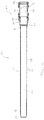
- the overtube 10 includes an elongate flexible tubular member 14 having a proximal end 16 and a distal end 18, and a hub 20 provided at the proximal end 16 of the tubular member 14.
- the tubular member 14 has a length sufficient to extend from the mouth, through the alimentary canal and to the stomach of the patient, e.g., approximately 27 cm, however the tubular member can be provided in other lengths suitable for a particular procedure and the respective intraluminal passage.
- the tubular member 14 defines a central passage 22 through which the endoscope 12 is received, and includes a resilient and flexible distal tip 24 at its distal end 18 that tapers to a close fitting diameter for the outer diameter of the endoscope(s) 12 for which the overtube 10 is intended to be used.
- an embodiment of the overtube is designed to accommodate endoscopes having an outer diameter between 10 to 14 mm, defines a central tubular passage 22 with a diameter of 17 mm, and has a distal tip 24 that tapers to a diameter of approximately 11 mm.
- the tubular member 14 is preferably a polymeric extrusion reinforced with a metal spring wire coil 26 extending through or along its wall 28 for the length of the extrusion, except at its distal tip 24 where increased flexibility is desired and at a proximal coupling portion 30.
- the tubular member construction is laterally flexible, but sufficiently reinforced to remain patent and longitudinally stiff during insertion into a natural orifice and under conditions of use.
- the distal tip 24 is preferably formed of a resilient material having elastic properties and may be integrally formed or joined to tubular member 14.
- the hub 20 is an assembly of five components including an inner tube collar 32 and an outer tube collar 34 that together engage the proximal coupling portion 30 of the tubular member 14, a tubular body member 36 provided with a fluid line connector 38, a flexible sleeve 40 extending through the body member 36, and a hub collar 42 coupled to a proximal end of the body member 36.
- the body member 36 is coupled to each of the tubular member 14 and to the flexible sleeve 40 using a snap-fit engagement of inner and outer tube collars 32, 34 at its distal end, and the hub collar 42 at its proximal end, such that no fasteners, welds, glues, etc. are necessary for securing the hub assembly together, as well as securing the hub assembly 20 to the tubular member 14.
- the inner tube collar 32 includes a tubular portion 44 including a barb 46, a central circumferential retaining groove 48, and a relatively larger diameter proximal flange 50 including a plurality of radially displaced engagement windows 52.
- the outer tube collar 34 includes a distal tubular portion 54 sized to closely receive the proximal coupling portion 30 of the flexible tubular member 14, a larger diameter central portion 56 sized to receive the tubular portion 44 of the inner collar 32, and a relatively larger diameter proximal portion 58 provided with catches 60 to engage the retaining groove 48 of the inner collar 32 to mechanically engage the inner and outer collars 32, 34 relative to each other.
- the tubular portion 44 of the inner collar 32 is inserted into the proximal coupling portion 30 of the tubular member 14 with the barb 46 making positive engagement within the inner surface of the tubular member.
- the outer collar 34 is advanced over the tubular member 14 such that the tubular portion 14 of the inner collar 32 extends to the end of the central portion 56 of the outer collar 34 and the catches 60 engage the retaining groove 48 to lock the collars 32, 34 together about the tubular member 14.
- the tubular member 14 is locked to the inner and outer collars 32, 34 by the tight interference fit created and the positive engagement of the barb 46 against the inner surface of the tubular member 14 and the outer collar 34 over the outside of the tubular member.
- the body member 36 includes a first end 62 defining a first circumferential groove 64 and a first plurality of catch barbs 66, a central portion 68, and a second end 70 defining a second plurality of catch barbs 72 and a second circumferential groove 74.
- the central portion 68 is preferably concave about its circumference to facilitate manual gripping thereof.
- the fluid line connector 38 is preferably in the form of a leur connector and extends radially outward from the central portion 68 and communicates with a smooth tubular interior 78 of the body member 36.
- the tubular interior 78 defines a first diameter D1 generally slightly larger than the diameter of the central passage 22.
- the body member 36 is longitudinally symmetrical such that either the first or second ends 62, 70 of the body member 36 may be the proximal or distal end for connection to either the inner collar 32 and hub collar 42, as described below, thereby aiding assembly.
- the flexible sleeve 40 extends through the tubular interior 78 of the body member 36 and has ends each defining an O-ring 82, 84.
- the flexible sleeve 40 is preferably made from polyisoprene or latex, though other elastic materials may be used.
- the O-rings 82, 84 may be joined to ends of flexible sleeve 40 or preferably integrally formed by rolling the ends of the flexible sleeve 40.
- the ends of the flexible sleeve40 are everted over the first and second ends 62, 70 of the body member 36 with the O-rings 82, 84 seated in first and second grooves 64, 74, respectively, as shown in Fig. 4 .
- the first end 62 of the body member 36 is then inserted into the flange 50 of the inner collar 32 in sufficient close tolerance such that first O-ring 82 of the flexible sleeve 40 is locked within groove 64, and such that the first plurality of catch barbs 66 extend through engagement windows 52 to lock the body member 36 relative to the inner collar 32 and thus relative to the tubular member 14.
- the hub collar 42 is a tubular portion defining a plurality of engagement windows 86, a locking surface 88, and an inverted portion forming a hub mouth 90.
- the hub collar 42 is positioned over the second end 70 of the body member 36 such that the second plurality of catch barbs 72 extend through the engagement windows 86 to lock the hub collar 42 relative to the body member 36, the locking surface 88 abuts the O-ring 84 to secure it within the second groove 74, and the hub mouth defines a proximal entry into the overtube 10.
- an inflation device 100 may be coupled to the fluid connector 38 of the hub 20.
- One exemplar inflation device 100 includes a syringe 102 for generating fluid pressure, a fluid line 104 for communicating the fluid pressure to the fluid connector 38, and a stopcock 106 for maintaining a fluid pressure.
- fluid such as air
- the fluid enters between the smooth interior 78 of the body member 36 and the outer surface of the flexible sleeve40, causing radially inward distension of a central portion of the seal cuff within the body member 36, such that the seal cuff defines a second hub diameter D2 smaller than the first hub diameter Dl, as shown in Fig.
- the stopcock 106 can be rotated to maintain the pressure and seal.
- the stopcock 106 is rotated to release the pressure and deactivate the seal.
- the syringe 102 is then preferably operated to withdraw all, or substantially all, fluid from between the flexible sleeve 40 and the body member 36 to allow the endoscope 12 to be freely removed from the overtube 10.
- an overtube for an endoscope for use through a natural body orifice such as a mouth. While a particular embodiment of the invention has been described above, it is not intended that the invention be limited thereto. Thus, while particular structure for coupling the various elements of the hub together have been described, it will be appreciated that other preferably snap-fit engagement structure can be used as well.
Claims (9)
- Überrohr (10) zur Verwendung mit einem Endoskop (12), das eine Außenfläche aufweist und zum Einsetzen durch eine natürliche Körperöffnung eines Patienten bestimmt ist, wobei das Überrohr (10) das Folgende umfasst:a) ein röhrenförmiges Element (14) mit einem proximalen Abschnitt (30) und einem distalen Abschnitt (18) und einer Länge dazwischen, die ausreicht, um sich vom Mund eines Patienten zum Magen eines Patienten zu erstrecken, wobei das röhrenförmige Element (14) einen mittigen Durchgang (22) zur Aufnahme des Endoskops (12) dort hindurch definiert; undb) eine Ansatzanordnung (20), die mit dem proximalen Abschnitt (30) gekoppelt ist, wobei die Ansatzanordnung (20) das Folgende aufweist
ein längssymmetrisches starres Körperelement (36) mit einem ersten Ende (62), einem zweiten Ende (70), einer Innenfläche (78), die einen glatten mittigen Durchgang definiert, einer Außenfläche und einem Fluidverbinder (38),
eine flexible Hülse (40), die sich innerhalb des mittigen Durchgangs des Körperelements erstreckt, wobei die Hülse (40) eine Außenfläche, eine Innenfläche und erste und zweite Enden aufweist, wobei die ersten und zweiten Enden bezüglich des Körperelements (36) gekoppelt sind, und die Außenfläche der Hülse und die Innenfläche (78) des Körperelements mit dem Fluidverbinder (38) in Verbindung stehen,
einen inneren Kragen (32), der sich teilweise in den proximalen Abschnitt (30) des röhrenförmigen Elements (14) erstreckt,
einen äußeren Kragen (34), der sich über den proximalen Abschnitt (30) des röhrenförmigen Elements (14) und den inneren Kragen (32) erstreckt, um den proximalen Abschnitt des röhrenförmigen Körpers in Eingriff zu nehmen und den proximalen Abschnitt (30) zwischen dem inneren und äußeren Kragen (32, 34) anzuordnen,
wobei der innere Kragen (32) mit einem Rasteingriff mit dem ersten Ende (62) des Körperelements gekoppelt ist, und der äußere Kragen (34) mit einem Rasteingriff mit dem inneren Kragen (32) gekoppelt ist, um den proximalen Abschnitt (30) des röhrenförmigen Elements dazwischen zu sichern, und
einen proximalen Ansatzkragen (42), der eine proximale Mündung (90) durch die Ansatzanordnung (20) definiert, wobei der Ansatzkragen (42) mit einem Rasteingriff am zweiten Ende (70) des Körperelements verriegelt ist,
wobei, wenn eine Flüssigkeit unter Druck durch den Fluidverbinder (38) bereitgestellt wird, sich die Hülse (40) radial nach innen ausdehnt, um eine Öffnung zu definieren, die kleiner als der mittige Durchgang (22) ist. - Überrohr nach Anspruch 1, wobei:der innere Kragen (32) einen äußeren Widerhaken (46) aufweist, der in das proximale Ende (30) des röhrenförmigen Elements (14) einführt wird.
- Überrohr nach Anspruch 1 oder Anspruch 2, wobei:der innere Kragen (32) eine Umfangshalterille (48) aufweist und der äußere Kragen (34) Sperrstücke (60) aufweist, welche die Halterille (48) des inneren Kragens (32) in Eingriff nehmen, um den inneren und den äußeren Kragen mit einem Rasteingriff miteinander zu koppeln.
- Überrohr nach einem der Ansprüche 1 bis 3, wobei:der innere Kragen (32) einen proximalen Flansch (50) mit einer Vielzahl von radial versetzten Eingriffsfenstern (52) aufweist und das erste Ende (62) des Körperelements eine Vielzahl von Sperrwiderhaken (66) aufweist, die in die Eingriffsfenster (52) einrasten, um den inneren Kragen (32) und das Körperelement (36) mit einem Rasteingriff miteinander zu koppeln.
- Überrohr nach einem der vorhergehenden Ansprüche, wobei:der Ansatzkragen (42) eine Vielzahl von radial versetzten Eingriffsfenstern (86) aufweist und das zweite Ende (70) des Körperelements eine Vielzahl von Einfangwiderhaken (72) aufweist, die in die Eingriffsfenster (86) des Ansatzkragens (42) einrasten, um den Ansatzkragen (42) und das Körperelement (36) mit einem Rasteingriff miteinander zu koppeln.
- Überrohr nach einem der vorhergehenden Ansprüche, wobei:das röhrenförmige Element (14) verstärkt ist, um während des Einsetzens in die natürliche Öffnung durchgängig und längs steif zu bleiben, während es seitlich ausreichend flexibel zum Einsetzen durch eine nicht gerade natürliche Öffnung bleibt.
- Überrohr nach Anspruch 6, wobei:das röhrenförmige Element (14) ein Polymer umfasst, das mit einer Metallspirale (26) verstärkt ist, und/oderdie Hülse (40) elastisch ist.
- Überrohr (10) nach Anspruch 7, wobei die Hülse (40) Polyisopren oder Latex umfasst.
- Überrohr (10) nach einem der vorhergehenden Ansprüche, in Kombination mit dem Endoskop (12), wobei, wenn sich das Endoskop (12) durch die Ansatzanordnung (20) erstreckt und die Flüssigkeit unter Druck durch den Fluidverbinder (38) bereitgestellt wird, sich die Hülse (40) radial nach innen ausdehnt, um eine Dichtung um das Endoskop (12) zu bilden.
Applications Claiming Priority (2)
| Application Number | Priority Date | Filing Date | Title |
|---|---|---|---|
| US13/551,942 US9386910B2 (en) | 2012-07-18 | 2012-07-18 | Endoscope overtube for insertion through a natural body orifice |
| PCT/US2013/049830 WO2014014715A1 (en) | 2012-07-18 | 2013-07-10 | Endoscope overtube for natural body orifice insertion |
Publications (3)
| Publication Number | Publication Date |
|---|---|
| EP2874533A1 EP2874533A1 (de) | 2015-05-27 |
| EP2874533A4 EP2874533A4 (de) | 2016-04-06 |
| EP2874533B1 true EP2874533B1 (de) | 2019-02-06 |
Family
ID=49947117
Family Applications (1)
| Application Number | Title | Priority Date | Filing Date |
|---|---|---|---|
| EP13819514.4A Active EP2874533B1 (de) | 2012-07-18 | 2013-07-10 | Endoskopüberrohr zum einsetzen in natürliche körperöffnungen |
Country Status (10)
| Country | Link |
|---|---|
| US (1) | US9386910B2 (de) |
| EP (1) | EP2874533B1 (de) |
| JP (1) | JP6251261B2 (de) |
| AU (1) | AU2013290586B2 (de) |
| BR (1) | BR112015000849A2 (de) |
| CA (1) | CA2879062A1 (de) |
| MX (1) | MX355845B (de) |
| NZ (1) | NZ703877A (de) |
| RU (1) | RU2642953C2 (de) |
| WO (1) | WO2014014715A1 (de) |
Families Citing this family (20)
| Publication number | Priority date | Publication date | Assignee | Title |
|---|---|---|---|---|
| JP6076469B2 (ja) | 2012-05-09 | 2017-02-08 | イーオン サージカル リミテッド | 腹腔鏡ポート |
| US9687273B2 (en) | 2013-09-11 | 2017-06-27 | Gimmi Gmbh | Endoscopic surgical instruments and related methods |
| USD755378S1 (en) * | 2014-09-30 | 2016-05-03 | Fujifilm Corporation | Endoscope |
| EP3263010A4 (de) * | 2015-02-26 | 2018-11-21 | Olympus Corporation | Überrohr für ein endoskop und medizinisches system |
| CN104856637B (zh) * | 2015-05-21 | 2016-05-25 | 施婷婷 | 一种带有照明装置的口腔扩撑器 |
| JP6595232B2 (ja) | 2015-07-02 | 2019-10-23 | ソニー・オリンパスメディカルソリューションズ株式会社 | 内視鏡用撮像装置、内視鏡装置、及び内視鏡用ケーブル |
| CN108495582B (zh) | 2015-09-03 | 2020-10-02 | 海王星医疗公司 | 用于使内窥镜穿过小肠推进的器械 |
| WO2017120263A1 (en) * | 2016-01-04 | 2017-07-13 | Endovate Llc | Overtube device and method of use |
| EP3407771A1 (de) * | 2016-01-29 | 2018-12-05 | Boston Scientific Scimed, Inc. | Aufsatz für eine abbildungsvorrichtung |
| WO2018035452A1 (en) | 2016-08-18 | 2018-02-22 | Neptune Medical | Device and method for enhanced visualization of the small intestine |
| CN106267520A (zh) * | 2016-08-29 | 2017-01-04 | 李安 | 用于胃管的图像采集置入装置以及胃管系统 |
| US20180228511A1 (en) * | 2017-02-13 | 2018-08-16 | Apurba Mukherjee | Modular Autoclavable Introducer for Endoscope |
| WO2018194146A1 (ja) * | 2017-04-19 | 2018-10-25 | Hoya株式会社 | 内視鏡頂部の取り付け装置 |
| JP2021531111A (ja) | 2018-07-19 | 2021-11-18 | ネプチューン メディカル インク. | 動的硬化医療用複合構造 |
| US11793392B2 (en) | 2019-04-17 | 2023-10-24 | Neptune Medical Inc. | External working channels |
| WO2021181503A1 (ja) * | 2020-03-10 | 2021-09-16 | オリンパス株式会社 | 内視鏡用オーバーチューブ、内視鏡システム、および内視鏡の挿入方法 |
| EP4126095A4 (de) | 2020-03-30 | 2024-04-24 | Neptune Medical Inc | Geschichtete wände für versteifungsvorrichtungen |
| CN112401973B (zh) * | 2020-11-19 | 2022-09-27 | 上海腾复医疗科技有限公司 | 多功能鞘管 |
| WO2022208737A1 (ja) * | 2021-03-31 | 2022-10-06 | オリンパス株式会社 | 内視鏡用オーバーチューブ |
| US20230346204A1 (en) | 2022-04-27 | 2023-11-02 | Neptune Medical Inc. | Endoscope sheath apparatuses |
Family Cites Families (40)
| Publication number | Priority date | Publication date | Assignee | Title |
|---|---|---|---|---|
| US2325831A (en) | 1943-08-03 | Cavitstinspection device | ||
| US3057345A (en) | 1960-05-16 | 1962-10-09 | Bausch & Lomb | Duodenoscope |
| US4701160A (en) * | 1986-06-11 | 1987-10-20 | Minnesota Mining And Manufacturing Company | Catheter and method for infusing fluid into a patient |
| US4900306A (en) | 1988-01-15 | 1990-02-13 | Corpak, Inc. | Device for intubation of percutaneous endoscopic ostomy |
| US4875468A (en) | 1988-12-23 | 1989-10-24 | Welch Allyn, Inc. | Elastomer-ePTFE biopsy channel |
| US5161773A (en) * | 1990-08-01 | 1992-11-10 | Numed, Inc. | Method and apparatus for controlling fluid flow |
| US5158553A (en) | 1990-12-26 | 1992-10-27 | Cardiopulmonics | Rotatably actuated constricting catheter valve |
| DE4312147C2 (de) | 1992-04-14 | 1996-01-25 | Olympus Optical Co | Trokar |
| US5556367A (en) | 1993-03-05 | 1996-09-17 | Olympus Optical Co., Ltd. | Cover type endoscope apparatus |
| AU4242996A (en) * | 1994-11-23 | 1996-06-17 | Navarre Biomedical, Ltd. | Flexible catheter |
| US5620408A (en) | 1995-04-14 | 1997-04-15 | Vennes; Jack A. | Endoscopic over-tube |
| US6030364A (en) | 1997-10-03 | 2000-02-29 | Boston Scientific Corporation | Apparatus and method for percutaneous placement of gastro-intestinal tubes |
| US6174280B1 (en) | 1998-11-19 | 2001-01-16 | Vision Sciences, Inc. | Sheath for protecting and altering the bending characteristics of a flexible endoscope |
| US6530881B1 (en) | 1999-01-21 | 2003-03-11 | Vision Sciences, Inc. | Sheath apparatus for endoscopes and methods for forming same |
| IL128286A (en) | 1999-01-29 | 2004-01-04 | Sightline Techn Ltd | Movement gracefully inside the bowel using a flexible sleeve |
| US7128708B2 (en) | 2002-06-13 | 2006-10-31 | Usgi Medical Inc. | Shape lockable apparatus and method for advancing an instrument through unsupported anatomy |
| AU2001244487A1 (en) | 2000-03-23 | 2001-10-03 | Atropos Limited | An insertion device for an endoscope |
| US7083629B2 (en) | 2001-05-30 | 2006-08-01 | Satiety, Inc. | Overtube apparatus for insertion into a body |
| JP3831683B2 (ja) | 2002-05-16 | 2006-10-11 | ペンタックス株式会社 | 外套シース付き内視鏡の挿入部可撓管の折れ止め |
| US6790214B2 (en) | 2002-05-17 | 2004-09-14 | Esophyx, Inc. | Transoral endoscopic gastroesophageal flap valve restoration device, assembly, system and method |
| US6899672B2 (en) | 2002-11-08 | 2005-05-31 | Scimed Life Systems, Inc. | Endoscopic imaging system including removable deflection device |
| WO2004071284A1 (ja) * | 2003-02-11 | 2004-08-26 | Olympus Corporation | オーバーチューブ、オーバーチューブの製造方法、オーバーチューブの配置方法、および腹腔内の処置方法 |
| US20070203393A1 (en) | 2003-05-16 | 2007-08-30 | David Stefanchik | Apparatus for positioning a medical device |
| JP4383115B2 (ja) * | 2003-07-31 | 2009-12-16 | オリンパス株式会社 | 内視鏡システム |
| JP3826928B2 (ja) * | 2003-10-14 | 2006-09-27 | フジノン株式会社 | 内視鏡の挿入補助具 |
| FR2872696B1 (fr) * | 2004-07-07 | 2007-09-28 | Perouse Soc Par Actions Simpli | Introducteur pour intervention endoluminale |
| US20060047183A1 (en) | 2004-09-01 | 2006-03-02 | Chul Hi Park | Inflatable guide device |
| US20070255101A1 (en) | 2005-03-04 | 2007-11-01 | Sightline Technologies Ltd. | Endoscope with Protective Sleeve |
| US7905830B2 (en) | 2005-05-13 | 2011-03-15 | Ethicon Endo-Surgery, Inc. | Sheath for use with an endoscope |
| US8021293B2 (en) | 2006-01-13 | 2011-09-20 | Olympus Medical Systems Corp. | Medical treatment endoscope |
| US8012086B2 (en) | 2006-10-19 | 2011-09-06 | Ethicon Endo-Surgery, Inc. | Sterile transcolonic access device |
| JP5171076B2 (ja) * | 2007-03-14 | 2013-03-27 | 富士フイルム株式会社 | 内視鏡装置 |
| WO2009094434A2 (en) | 2008-01-22 | 2009-07-30 | University Of South Florida | Endoscopic overtube |
| CN103961049B (zh) | 2008-03-31 | 2017-04-12 | 智能医疗系统有限公司 | 与内窥镜一起使用的组件 |
| US8262563B2 (en) | 2008-07-14 | 2012-09-11 | Ethicon Endo-Surgery, Inc. | Endoscopic translumenal articulatable steerable overtube |
| US20100010298A1 (en) | 2008-07-14 | 2010-01-14 | Ethicon Endo-Surgery, Inc. | Endoscopic translumenal flexible overtube |
| US20100076451A1 (en) | 2008-09-19 | 2010-03-25 | Ethicon Endo-Surgery, Inc. | Rigidizable surgical instrument |
| US9867529B2 (en) | 2008-11-07 | 2018-01-16 | Izoscope Inc | Endoscope accessory |
| US20100228090A1 (en) * | 2009-03-06 | 2010-09-09 | Ethicon Endo-Surgery, Inc. | Methods and devices for providing access into a body cavity |
| US20100298642A1 (en) | 2009-05-19 | 2010-11-25 | Ethicon Endo-Surgery, Inc. | Manipulatable guide system and methods for natural orifice translumenal endoscopic surgery |
-
2012
- 2012-07-18 US US13/551,942 patent/US9386910B2/en active Active
-
2013
- 2013-07-10 AU AU2013290586A patent/AU2013290586B2/en active Active
- 2013-07-10 BR BR112015000849A patent/BR112015000849A2/pt not_active Application Discontinuation
- 2013-07-10 CA CA2879062A patent/CA2879062A1/en not_active Abandoned
- 2013-07-10 WO PCT/US2013/049830 patent/WO2014014715A1/en active Application Filing
- 2013-07-10 JP JP2015523128A patent/JP6251261B2/ja active Active
- 2013-07-10 NZ NZ703877A patent/NZ703877A/en unknown
- 2013-07-10 EP EP13819514.4A patent/EP2874533B1/de active Active
- 2013-07-10 RU RU2015105387A patent/RU2642953C2/ru active
- 2013-07-10 MX MX2015000647A patent/MX355845B/es active IP Right Grant
Non-Patent Citations (1)
| Title |
|---|
| None * |
Also Published As
| Publication number | Publication date |
|---|---|
| MX2015000647A (es) | 2015-07-17 |
| RU2642953C2 (ru) | 2018-01-29 |
| NZ703877A (en) | 2017-02-24 |
| MX355845B (es) | 2018-05-02 |
| AU2013290586A1 (en) | 2015-02-05 |
| BR112015000849A2 (pt) | 2017-06-27 |
| US9386910B2 (en) | 2016-07-12 |
| RU2015105387A (ru) | 2016-09-10 |
| WO2014014715A1 (en) | 2014-01-23 |
| US20140024896A1 (en) | 2014-01-23 |
| JP2015524297A (ja) | 2015-08-24 |
| AU2013290586B2 (en) | 2016-12-15 |
| EP2874533A4 (de) | 2016-04-06 |
| JP6251261B2 (ja) | 2017-12-20 |
| EP2874533A1 (de) | 2015-05-27 |
| CA2879062A1 (en) | 2014-01-23 |
Similar Documents
| Publication | Publication Date | Title |
|---|---|---|
| EP2874533B1 (de) | Endoskopüberrohr zum einsetzen in natürliche körperöffnungen | |
| JP2015524297A5 (de) | ||
| US7771396B2 (en) | Intubation device for enteral feeding | |
| CA2582268C (en) | Intubation system for use with an endoscope | |
| US8267873B2 (en) | Guidewire catheter | |
| US20160235438A1 (en) | Instrument access device | |
| US20100063358A1 (en) | Channeled flexible sleeve for medical articles | |
| EP1839555B1 (de) | Medizinische Schlingenvorrichtung | |
| TWI428111B (zh) | 醫療用保持器 | |
| JP2007501650A (ja) | 胃腸洗浄装置 | |
| CA2582818C (en) | Intubation device for colonic decompression | |
| US8460248B2 (en) | Endoscopic bite guard and related methods of use | |
| JP2005230082A (ja) | 内視鏡用オーバチューブ | |
| WO2010002786A2 (en) | Method and system for endoscopic placement of a balloon |
Legal Events
| Date | Code | Title | Description |
|---|---|---|---|
| PUAI | Public reference made under article 153(3) epc to a published international application that has entered the european phase |
Free format text: ORIGINAL CODE: 0009012 |
|
| 17P | Request for examination filed |
Effective date: 20150128 |
|
| AK | Designated contracting states |
Kind code of ref document: A1 Designated state(s): AL AT BE BG CH CY CZ DE DK EE ES FI FR GB GR HR HU IE IS IT LI LT LU LV MC MK MT NL NO PL PT RO RS SE SI SK SM TR |
|
| AX | Request for extension of the european patent |
Extension state: BA ME |
|
| DAX | Request for extension of the european patent (deleted) | ||
| RA4 | Supplementary search report drawn up and despatched (corrected) |
Effective date: 20160303 |
|
| RIC1 | Information provided on ipc code assigned before grant |
Ipc: G02B 23/24 20060101ALN20160226BHEP Ipc: A61B 1/24 20060101ALI20160226BHEP Ipc: A61B 1/273 20060101AFI20160226BHEP Ipc: A61B 1/00 20060101ALI20160226BHEP Ipc: A61B 1/12 20060101ALI20160226BHEP |
|
| STAA | Information on the status of an ep patent application or granted ep patent |
Free format text: STATUS: EXAMINATION IS IN PROGRESS |
|
| 17Q | First examination report despatched |
Effective date: 20170609 |
|
| REG | Reference to a national code |
Ref country code: DE Ref legal event code: R079 Ref document number: 602013050576 Country of ref document: DE Free format text: PREVIOUS MAIN CLASS: A61B0001273000 Ipc: A61B0001000000 |
|
| GRAP | Despatch of communication of intention to grant a patent |
Free format text: ORIGINAL CODE: EPIDOSNIGR1 |
|
| STAA | Information on the status of an ep patent application or granted ep patent |
Free format text: STATUS: GRANT OF PATENT IS INTENDED |
|
| RIC1 | Information provided on ipc code assigned before grant |
Ipc: A61B 17/34 20060101ALI20180725BHEP Ipc: A61M 39/22 20060101ALI20180725BHEP Ipc: A61B 1/273 20060101ALI20180725BHEP Ipc: A61B 1/24 20060101ALI20180725BHEP Ipc: A61B 1/12 20060101ALI20180725BHEP Ipc: A61M 39/06 20060101ALI20180725BHEP Ipc: A61B 1/00 20060101AFI20180725BHEP Ipc: G02B 23/24 20060101ALN20180725BHEP |
|
| INTG | Intention to grant announced |
Effective date: 20180820 |
|
| GRAS | Grant fee paid |
Free format text: ORIGINAL CODE: EPIDOSNIGR3 |
|
| GRAA | (expected) grant |
Free format text: ORIGINAL CODE: 0009210 |
|
| STAA | Information on the status of an ep patent application or granted ep patent |
Free format text: STATUS: THE PATENT HAS BEEN GRANTED |
|
| AK | Designated contracting states |
Kind code of ref document: B1 Designated state(s): AL AT BE BG CH CY CZ DE DK EE ES FI FR GB GR HR HU IE IS IT LI LT LU LV MC MK MT NL NO PL PT RO RS SE SI SK SM TR |
|
| REG | Reference to a national code |
Ref country code: GB Ref legal event code: FG4D |
|
| REG | Reference to a national code |
Ref country code: CH Ref legal event code: EP Ref country code: AT Ref legal event code: REF Ref document number: 1094334 Country of ref document: AT Kind code of ref document: T Effective date: 20190215 |
|
| REG | Reference to a national code |
Ref country code: IE Ref legal event code: FG4D |
|
| REG | Reference to a national code |
Ref country code: DE Ref legal event code: R096 Ref document number: 602013050576 Country of ref document: DE |
|
| REG | Reference to a national code |
Ref country code: NL Ref legal event code: MP Effective date: 20190206 |
|
| REG | Reference to a national code |
Ref country code: LT Ref legal event code: MG4D |
|
| PG25 | Lapsed in a contracting state [announced via postgrant information from national office to epo] |
Ref country code: LT Free format text: LAPSE BECAUSE OF FAILURE TO SUBMIT A TRANSLATION OF THE DESCRIPTION OR TO PAY THE FEE WITHIN THE PRESCRIBED TIME-LIMIT Effective date: 20190206 Ref country code: FI Free format text: LAPSE BECAUSE OF FAILURE TO SUBMIT A TRANSLATION OF THE DESCRIPTION OR TO PAY THE FEE WITHIN THE PRESCRIBED TIME-LIMIT Effective date: 20190206 Ref country code: SE Free format text: LAPSE BECAUSE OF FAILURE TO SUBMIT A TRANSLATION OF THE DESCRIPTION OR TO PAY THE FEE WITHIN THE PRESCRIBED TIME-LIMIT Effective date: 20190206 Ref country code: PT Free format text: LAPSE BECAUSE OF FAILURE TO SUBMIT A TRANSLATION OF THE DESCRIPTION OR TO PAY THE FEE WITHIN THE PRESCRIBED TIME-LIMIT Effective date: 20190606 Ref country code: NO Free format text: LAPSE BECAUSE OF FAILURE TO SUBMIT A TRANSLATION OF THE DESCRIPTION OR TO PAY THE FEE WITHIN THE PRESCRIBED TIME-LIMIT Effective date: 20190506 Ref country code: NL Free format text: LAPSE BECAUSE OF FAILURE TO SUBMIT A TRANSLATION OF THE DESCRIPTION OR TO PAY THE FEE WITHIN THE PRESCRIBED TIME-LIMIT Effective date: 20190206 |
|
| REG | Reference to a national code |
Ref country code: AT Ref legal event code: MK05 Ref document number: 1094334 Country of ref document: AT Kind code of ref document: T Effective date: 20190206 |
|
| PG25 | Lapsed in a contracting state [announced via postgrant information from national office to epo] |
Ref country code: GR Free format text: LAPSE BECAUSE OF FAILURE TO SUBMIT A TRANSLATION OF THE DESCRIPTION OR TO PAY THE FEE WITHIN THE PRESCRIBED TIME-LIMIT Effective date: 20190507 Ref country code: BG Free format text: LAPSE BECAUSE OF FAILURE TO SUBMIT A TRANSLATION OF THE DESCRIPTION OR TO PAY THE FEE WITHIN THE PRESCRIBED TIME-LIMIT Effective date: 20190506 Ref country code: RS Free format text: LAPSE BECAUSE OF FAILURE TO SUBMIT A TRANSLATION OF THE DESCRIPTION OR TO PAY THE FEE WITHIN THE PRESCRIBED TIME-LIMIT Effective date: 20190206 Ref country code: HR Free format text: LAPSE BECAUSE OF FAILURE TO SUBMIT A TRANSLATION OF THE DESCRIPTION OR TO PAY THE FEE WITHIN THE PRESCRIBED TIME-LIMIT Effective date: 20190206 Ref country code: LV Free format text: LAPSE BECAUSE OF FAILURE TO SUBMIT A TRANSLATION OF THE DESCRIPTION OR TO PAY THE FEE WITHIN THE PRESCRIBED TIME-LIMIT Effective date: 20190206 Ref country code: IS Free format text: LAPSE BECAUSE OF FAILURE TO SUBMIT A TRANSLATION OF THE DESCRIPTION OR TO PAY THE FEE WITHIN THE PRESCRIBED TIME-LIMIT Effective date: 20190606 |
|
| PG25 | Lapsed in a contracting state [announced via postgrant information from national office to epo] |
Ref country code: ES Free format text: LAPSE BECAUSE OF FAILURE TO SUBMIT A TRANSLATION OF THE DESCRIPTION OR TO PAY THE FEE WITHIN THE PRESCRIBED TIME-LIMIT Effective date: 20190206 Ref country code: AL Free format text: LAPSE BECAUSE OF FAILURE TO SUBMIT A TRANSLATION OF THE DESCRIPTION OR TO PAY THE FEE WITHIN THE PRESCRIBED TIME-LIMIT Effective date: 20190206 Ref country code: EE Free format text: LAPSE BECAUSE OF FAILURE TO SUBMIT A TRANSLATION OF THE DESCRIPTION OR TO PAY THE FEE WITHIN THE PRESCRIBED TIME-LIMIT Effective date: 20190206 Ref country code: IT Free format text: LAPSE BECAUSE OF FAILURE TO SUBMIT A TRANSLATION OF THE DESCRIPTION OR TO PAY THE FEE WITHIN THE PRESCRIBED TIME-LIMIT Effective date: 20190206 Ref country code: DK Free format text: LAPSE BECAUSE OF FAILURE TO SUBMIT A TRANSLATION OF THE DESCRIPTION OR TO PAY THE FEE WITHIN THE PRESCRIBED TIME-LIMIT Effective date: 20190206 Ref country code: RO Free format text: LAPSE BECAUSE OF FAILURE TO SUBMIT A TRANSLATION OF THE DESCRIPTION OR TO PAY THE FEE WITHIN THE PRESCRIBED TIME-LIMIT Effective date: 20190206 Ref country code: SK Free format text: LAPSE BECAUSE OF FAILURE TO SUBMIT A TRANSLATION OF THE DESCRIPTION OR TO PAY THE FEE WITHIN THE PRESCRIBED TIME-LIMIT Effective date: 20190206 Ref country code: CZ Free format text: LAPSE BECAUSE OF FAILURE TO SUBMIT A TRANSLATION OF THE DESCRIPTION OR TO PAY THE FEE WITHIN THE PRESCRIBED TIME-LIMIT Effective date: 20190206 |
|
| REG | Reference to a national code |
Ref country code: DE Ref legal event code: R097 Ref document number: 602013050576 Country of ref document: DE |
|
| PG25 | Lapsed in a contracting state [announced via postgrant information from national office to epo] |
Ref country code: SM Free format text: LAPSE BECAUSE OF FAILURE TO SUBMIT A TRANSLATION OF THE DESCRIPTION OR TO PAY THE FEE WITHIN THE PRESCRIBED TIME-LIMIT Effective date: 20190206 Ref country code: PL Free format text: LAPSE BECAUSE OF FAILURE TO SUBMIT A TRANSLATION OF THE DESCRIPTION OR TO PAY THE FEE WITHIN THE PRESCRIBED TIME-LIMIT Effective date: 20190206 |
|
| PLBE | No opposition filed within time limit |
Free format text: ORIGINAL CODE: 0009261 |
|
| STAA | Information on the status of an ep patent application or granted ep patent |
Free format text: STATUS: NO OPPOSITION FILED WITHIN TIME LIMIT |
|
| PG25 | Lapsed in a contracting state [announced via postgrant information from national office to epo] |
Ref country code: AT Free format text: LAPSE BECAUSE OF FAILURE TO SUBMIT A TRANSLATION OF THE DESCRIPTION OR TO PAY THE FEE WITHIN THE PRESCRIBED TIME-LIMIT Effective date: 20190206 |
|
| 26N | No opposition filed |
Effective date: 20191107 |
|
| PG25 | Lapsed in a contracting state [announced via postgrant information from national office to epo] |
Ref country code: MC Free format text: LAPSE BECAUSE OF FAILURE TO SUBMIT A TRANSLATION OF THE DESCRIPTION OR TO PAY THE FEE WITHIN THE PRESCRIBED TIME-LIMIT Effective date: 20190206 Ref country code: SI Free format text: LAPSE BECAUSE OF FAILURE TO SUBMIT A TRANSLATION OF THE DESCRIPTION OR TO PAY THE FEE WITHIN THE PRESCRIBED TIME-LIMIT Effective date: 20190206 |
|
| REG | Reference to a national code |
Ref country code: CH Ref legal event code: PL |
|
| PG25 | Lapsed in a contracting state [announced via postgrant information from national office to epo] |
Ref country code: TR Free format text: LAPSE BECAUSE OF FAILURE TO SUBMIT A TRANSLATION OF THE DESCRIPTION OR TO PAY THE FEE WITHIN THE PRESCRIBED TIME-LIMIT Effective date: 20190206 |
|
| REG | Reference to a national code |
Ref country code: BE Ref legal event code: MM Effective date: 20190731 |
|
| PG25 | Lapsed in a contracting state [announced via postgrant information from national office to epo] |
Ref country code: LU Free format text: LAPSE BECAUSE OF NON-PAYMENT OF DUE FEES Effective date: 20190710 Ref country code: CH Free format text: LAPSE BECAUSE OF NON-PAYMENT OF DUE FEES Effective date: 20190731 Ref country code: BE Free format text: LAPSE BECAUSE OF NON-PAYMENT OF DUE FEES Effective date: 20190731 Ref country code: LI Free format text: LAPSE BECAUSE OF NON-PAYMENT OF DUE FEES Effective date: 20190731 |
|
| PG25 | Lapsed in a contracting state [announced via postgrant information from national office to epo] |
Ref country code: FR Free format text: LAPSE BECAUSE OF NON-PAYMENT OF DUE FEES Effective date: 20190731 |
|
| PG25 | Lapsed in a contracting state [announced via postgrant information from national office to epo] |
Ref country code: IE Free format text: LAPSE BECAUSE OF NON-PAYMENT OF DUE FEES Effective date: 20190710 |
|
| PG25 | Lapsed in a contracting state [announced via postgrant information from national office to epo] |
Ref country code: CY Free format text: LAPSE BECAUSE OF FAILURE TO SUBMIT A TRANSLATION OF THE DESCRIPTION OR TO PAY THE FEE WITHIN THE PRESCRIBED TIME-LIMIT Effective date: 20190206 |
|
| PG25 | Lapsed in a contracting state [announced via postgrant information from national office to epo] |
Ref country code: MT Free format text: LAPSE BECAUSE OF FAILURE TO SUBMIT A TRANSLATION OF THE DESCRIPTION OR TO PAY THE FEE WITHIN THE PRESCRIBED TIME-LIMIT Effective date: 20190206 Ref country code: HU Free format text: LAPSE BECAUSE OF FAILURE TO SUBMIT A TRANSLATION OF THE DESCRIPTION OR TO PAY THE FEE WITHIN THE PRESCRIBED TIME-LIMIT; INVALID AB INITIO Effective date: 20130710 |
|
| PG25 | Lapsed in a contracting state [announced via postgrant information from national office to epo] |
Ref country code: MK Free format text: LAPSE BECAUSE OF FAILURE TO SUBMIT A TRANSLATION OF THE DESCRIPTION OR TO PAY THE FEE WITHIN THE PRESCRIBED TIME-LIMIT Effective date: 20190206 |
|
| P01 | Opt-out of the competence of the unified patent court (upc) registered |
Effective date: 20230530 |
|
| PGFP | Annual fee paid to national office [announced via postgrant information from national office to epo] |
Ref country code: GB Payment date: 20230727 Year of fee payment: 11 |
|
| PGFP | Annual fee paid to national office [announced via postgrant information from national office to epo] |
Ref country code: DE Payment date: 20230727 Year of fee payment: 11 |
|
| REG | Reference to a national code |
Ref country code: DE Ref legal event code: R081 Ref document number: 602013050576 Country of ref document: DE Owner name: BOSTON SCIENTIFIC SCIMED, INC., MAPLE GROVE, US Free format text: FORMER OWNER: APOLLO ENDOSURGERY US, INC., AUSTIN, TX, US Ref country code: DE Ref legal event code: R081 Ref document number: 602013050576 Country of ref document: DE Owner name: BOSTON SCIENTIFIC SCIMED, INC., MAPLE GROVE, US Free format text: FORMER OWNER: APOLLO ENDOSURGERY, INC., AUSTIN, TEX., US |
|
| REG | Reference to a national code |
Ref country code: GB Ref legal event code: 732E Free format text: REGISTERED BETWEEN 20240314 AND 20240320 |