EP2873777A1 - Wheel loader - Google Patents
Wheel loader Download PDFInfo
- Publication number
- EP2873777A1 EP2873777A1 EP14833566.4A EP14833566A EP2873777A1 EP 2873777 A1 EP2873777 A1 EP 2873777A1 EP 14833566 A EP14833566 A EP 14833566A EP 2873777 A1 EP2873777 A1 EP 2873777A1
- Authority
- EP
- European Patent Office
- Prior art keywords
- air cleaner
- wheel loader
- expansion member
- cab
- disposed
- Prior art date
- Legal status (The legal status is an assumption and is not a legal conclusion. Google has not performed a legal analysis and makes no representation as to the accuracy of the status listed.)
- Granted
Links
Images




Classifications
-
- E—FIXED CONSTRUCTIONS
- E02—HYDRAULIC ENGINEERING; FOUNDATIONS; SOIL SHIFTING
- E02F—DREDGING; SOIL-SHIFTING
- E02F9/00—Component parts of dredgers or soil-shifting machines, not restricted to one of the kinds covered by groups E02F3/00 - E02F7/00
- E02F9/08—Superstructures; Supports for superstructures
- E02F9/0833—Improving access, e.g. for maintenance, steps for improving driver's access, handrails
-
- B—PERFORMING OPERATIONS; TRANSPORTING
- B60—VEHICLES IN GENERAL
- B60K—ARRANGEMENT OR MOUNTING OF PROPULSION UNITS OR OF TRANSMISSIONS IN VEHICLES; ARRANGEMENT OR MOUNTING OF PLURAL DIVERSE PRIME-MOVERS IN VEHICLES; AUXILIARY DRIVES FOR VEHICLES; INSTRUMENTATION OR DASHBOARDS FOR VEHICLES; ARRANGEMENTS IN CONNECTION WITH COOLING, AIR INTAKE, GAS EXHAUST OR FUEL SUPPLY OF PROPULSION UNITS IN VEHICLES
- B60K13/00—Arrangement in connection with combustion air intake or gas exhaust of propulsion units
- B60K13/02—Arrangement in connection with combustion air intake or gas exhaust of propulsion units concerning intake
-
- B—PERFORMING OPERATIONS; TRANSPORTING
- B60—VEHICLES IN GENERAL
- B60R—VEHICLES, VEHICLE FITTINGS, OR VEHICLE PARTS, NOT OTHERWISE PROVIDED FOR
- B60R3/00—Arrangements of steps or ladders facilitating access to or on the vehicle, e.g. running-boards
-
- E—FIXED CONSTRUCTIONS
- E02—HYDRAULIC ENGINEERING; FOUNDATIONS; SOIL SHIFTING
- E02F—DREDGING; SOIL-SHIFTING
- E02F9/00—Component parts of dredgers or soil-shifting machines, not restricted to one of the kinds covered by groups E02F3/00 - E02F7/00
- E02F9/08—Superstructures; Supports for superstructures
- E02F9/0858—Arrangement of component parts installed on superstructures not otherwise provided for, e.g. electric components, fenders, air-conditioning units
- E02F9/0866—Engine compartment, e.g. heat exchangers, exhaust filters, cooling devices, silencers, mufflers, position of hydraulic pumps in the engine compartment
-
- E—FIXED CONSTRUCTIONS
- E06—DOORS, WINDOWS, SHUTTERS, OR ROLLER BLINDS IN GENERAL; LADDERS
- E06C—LADDERS
- E06C5/00—Ladders characterised by being mounted on undercarriages or vehicles Securing ladders on vehicles
- E06C5/02—Ladders characterised by being mounted on undercarriages or vehicles Securing ladders on vehicles with rigid longitudinal members
-
- E—FIXED CONSTRUCTIONS
- E06—DOORS, WINDOWS, SHUTTERS, OR ROLLER BLINDS IN GENERAL; LADDERS
- E06C—LADDERS
- E06C7/00—Component parts, supporting parts, or accessories
- E06C7/16—Platforms on, or for use on, ladders, e.g. liftable or lowerable platforms
-
- F—MECHANICAL ENGINEERING; LIGHTING; HEATING; WEAPONS; BLASTING
- F02—COMBUSTION ENGINES; HOT-GAS OR COMBUSTION-PRODUCT ENGINE PLANTS
- F02M—SUPPLYING COMBUSTION ENGINES IN GENERAL WITH COMBUSTIBLE MIXTURES OR CONSTITUENTS THEREOF
- F02M35/00—Combustion-air cleaners, air intakes, intake silencers, or induction systems specially adapted for, or arranged on, internal-combustion engines
- F02M35/02—Air cleaners
- F02M35/024—Air cleaners using filters, e.g. moistened
-
- F—MECHANICAL ENGINEERING; LIGHTING; HEATING; WEAPONS; BLASTING
- F02—COMBUSTION ENGINES; HOT-GAS OR COMBUSTION-PRODUCT ENGINE PLANTS
- F02M—SUPPLYING COMBUSTION ENGINES IN GENERAL WITH COMBUSTIBLE MIXTURES OR CONSTITUENTS THEREOF
- F02M35/00—Combustion-air cleaners, air intakes, intake silencers, or induction systems specially adapted for, or arranged on, internal-combustion engines
- F02M35/02—Air cleaners
- F02M35/04—Air cleaners specially arranged with respect to engine, to intake system or specially adapted to vehicle; Mounting thereon ; Combinations with other devices
- F02M35/048—Arranging or mounting on or with respect to engines or vehicle bodies
-
- F—MECHANICAL ENGINEERING; LIGHTING; HEATING; WEAPONS; BLASTING
- F02—COMBUSTION ENGINES; HOT-GAS OR COMBUSTION-PRODUCT ENGINE PLANTS
- F02M—SUPPLYING COMBUSTION ENGINES IN GENERAL WITH COMBUSTIBLE MIXTURES OR CONSTITUENTS THEREOF
- F02M35/00—Combustion-air cleaners, air intakes, intake silencers, or induction systems specially adapted for, or arranged on, internal-combustion engines
- F02M35/02—Air cleaners
- F02M35/0201—Housings; Casings; Frame constructions; Lids; Manufacturing or assembling thereof
-
- F—MECHANICAL ENGINEERING; LIGHTING; HEATING; WEAPONS; BLASTING
- F02—COMBUSTION ENGINES; HOT-GAS OR COMBUSTION-PRODUCT ENGINE PLANTS
- F02M—SUPPLYING COMBUSTION ENGINES IN GENERAL WITH COMBUSTIBLE MIXTURES OR CONSTITUENTS THEREOF
- F02M35/00—Combustion-air cleaners, air intakes, intake silencers, or induction systems specially adapted for, or arranged on, internal-combustion engines
- F02M35/02—Air cleaners
- F02M35/024—Air cleaners using filters, e.g. moistened
- F02M35/02475—Air cleaners using filters, e.g. moistened characterised by the shape of the filter element
- F02M35/02483—Cylindrical, conical, oval, spherical or the like filter elements; wounded filter elements
Definitions
- the present invention relates to a wheel loader.
- An exhaust gas post-treatment device is mounted on a wheel loader.
- the exhaust gas post-treatment device includes a diesel particulate filter device that collects and removes particulate matter of smoke and the like included in the diesel engine exhaust gas.
- the diesel particulate filter device is mounted in a row with an air cleaner above the engine.
- a nitrogen oxide reduction catalyst device may also be provided to remove NOx from the exhaust gas.
- the nitrogen oxide reduction catalyst device is provided on the exhaust downstream side of the diesel particulate filter device.
- the installation location of the nitrogen oxide reduction catalyst device becomes a problem if the nitrogen oxide reduction catalyst device is installed along with the diesel particulate filter device. Since the nitrogen oxide reduction catalyst device needs to be disposed on the exhaust downstream side of the diesel particulate filter device, generally the nitrogen oxide reduction catalyst device is mounted in a row with the air cleaner and the diesel particulate filter device above the engine if the nitrogen oxide reduction catalyst device is installed along with the diesel particulate filter device.
- Patent Document 1 a configuration has been proposed for a large-scale dump truck described in Patent Document 1 in which an engine room is provided beside the cab and an air cleaner is disposed on the outside of the engine room. With such a configuration, visibility to the rear is not reduced when the air cleaner is disposed on the upper portion of the engine room.
- Patent Document 1 Japanese Patent Laid-open No. 2003-335268
- An object of the present invention is to prevent a reduction in visibility to the rear and to enable ease of maintenance work in a wheel loader.
- a wheel loader is provided with a cab, a ladder, an expansion member, a vehicle body cover, an engine, and an air cleaner.
- the cab is provided with a driver seat inside the cab.
- the ladder is provided at a side of the cab.
- the ladder has a plurality of steps disposed with intervals therebetween.
- the expansion member assumes an expanded posture.
- the expansion member abuts at least one step and protrudes in the vehicle width direction when in the expanded posture.
- the vehicle body cover is disposed to the rear of the cab and demarcates an engine room.
- the engine is disposed inside the engine room.
- the air cleaner includes therein a filter that is exchangeable and cleans air supplied to the engine.
- the air cleaner is disposed outside of the vehicle body cover.
- the air cleaner is disposed above and to the rear of the expansion member when the expansion member assumes the expanded posture.
- the air cleaner in the wheel loader is provided on the outside of the vehicle body cover and is not provided in the engine room. According to this configuration, since the air cleaner is disposed outside of the engine room, a top plate of the engine room does not need to be made higher even if an exhaust gas post-treatment device is installed above the engine inside the engine room. Therefore, reduction in visibility to the rear can be avoided despite the installation of the exhaust gas post-treatment device.
- the air cleaner is disposed above and to the rear of the expansion member while the expansion member assumes the expanded posture, maintenance work on the air cleaner can be performed by the operator while on the ladder and the maintenance work can be performed easily.
- the expansion member abuts at least one step when the expansion member assumes the expanded posture.
- the operator is able to work while standing on the at least one step and the expansion member. In this way, the operator is able to perform the air cleaner maintenance work in a stable posture because the foothold for the operator is widened when working.
- the expansion member preferably assumes a retracted posture in which the expansion member is retracted from the at least one step. That is, the expansion member is able to assume the expanded posture and the retracted posture. According to this configuration, when the operator is not performing maintenance work, that is, when the ladder is used for climbing up to and down from the cab, the expansion member does not become an obstruction while climbing up to and down from the cab due to the retracted posture of the expansion member.
- the at least one step preferably has a length in the vehicle front-back direction greater than that of the other steps. According to this configuration, the operator is able to perform the maintenance work on the air cleaner while maintaining a stable posture.
- the air cleaner is preferably configured so that the filter can be pulled out toward the ladder and disposed so as to be inclined so that the pulling-out side of the filter is further away from the cab than the opposite side. According to this configuration, the operator is able to remove the filter easily while standing on the at least one step of the ladder.
- the wheel loader preferably is further provided with a platform disposed at the side of the cab.
- the expansion member is positioned under the platform in the retracted posture. According to this configuration, the expansion member does not become an obstruction when the operator uses the ladder for climbing up to and down from the cab due to the expansion member being positioned below the platform.
- the expansion member is preferably attached to the platform. According to this configuration, even if the ladder is deformed due to a collision, the expansion member can function effectively since the expansion member is attached to the platform and not to the ladder.
- the expansion member preferably has a fixed part, an arm part, and a flat part.
- the fixed part extends downward from the platform.
- the arm part couples to the lower end part of the fixed part is a swingable manner.
- the flat part extends from the arm part in the vehicle front-back direction. The flat part abuts the at least one step in the expanded posture. According to this configuration, the expansion member is able to selectively assume the expanded posture and the retracted posture by swinging the arm part with respect to the fixed part.
- the ladder preferably extends downward from the platform disposed at the side of the cab.
- a first step positioned at the top of the plurality of steps protrudes from the platform in the vehicle width direction. Steps other than the first step protrude in the vehicle width direction from one step above. A protrusion amount of each step is fixed.
- the operator is able to ascend and descend the steps of the ladder smoothly, the expansion member being positioned in the retracted posture.
- the ladder preferably has a front strut and a rear strut that extend in the vertical direction and that are disposed away from each other in the vehicle front-back direction.
- the steps extend so as to cross between the front strut and the rear strut.
- the rear strut has an upper part and a lower part.
- the upper part of the rear strut has attached thereto a first step positioned at the top and a second step positioned second from the top among the plurality of steps.
- the lower part of the rear strut has another step attached thereto and the lower part is positioned further toward the front than the upper part.
- the first and second steps are attached to the upper part of the rear strut and the upper part of the rear strut is positioned further to the rear than the lower part.
- the first and second steps extend further to the rear than the other steps and the operator is able to perform the maintenance work in a position near the air cleaner.
- the at least one step corresponds to the first step or the second step.
- the rear strut preferably further has a middle part that couples the upper part and the lower part.
- the middle part is inclined rearward in an upward direction as seen in a side view.
- the wheel loader preferably further has a handrail member provided along the rear strut.
- the handrail member has a vertical part that extends vertically.
- the vertical part is positioned to the outside of the rear strut in the vehicle width direction. According to this configuration, since the vertical part of the handrail member is positioned to the outside of the rear strut in the vehicle width direction, the operator is able to perform the maintenance work while applying his weight onto the vertical part, and consequently is able to perform the maintenance work of the air cleaner while maintaining a more stable posture.
- An upper edge of the handrail member is preferably positioned below the platform disposed at the side of the cab. According to this configuration, the operator will not trip over the handrail member while standing on the platform.
- the ladder preferably further has a supplementary step that is below the step positioned at the bottom and that hangs down with elastic strips.
- a supplementary step that is below the step positioned at the bottom and that hangs down with elastic strips.
- the cab preferably has a cab body and a door.
- the rear part of the door is supported by the cab body.
- the door can be opened and closed toward the front.
- the air cleaner is disposed at a location that does not obstruct the door when the door is fully open.
- the door is not obstructed by the air cleaner when the driver opens or closes the door to enter or exit the cab.
- the wheel loader preferably further includes an operating fluid tank disposed between the cab and the engine.
- the air cleaner is disposed at the side of the operating fluid tank.
- the wheel loader is preferably provided with a rear wheel fender disposed above a rear wheel.
- the air cleaner is fixed to an upper part of the rear wheel fender.
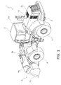
- FIG. 1 is a perspective view of a wheel loader as seen from the left rear.
- “right,” “left,” “up,” and “down” indicate directions relative to a state of looking forward from the operating cabin, and “vehicle width direction” and “left-right direction” have the same meaning. Further, “width” signifies a length in the left-right direction.
- a wheel loader 1 includes a vehicle body frame 2, a work implement 3, front wheels 4, rear wheels 5, and a cab 6 as illustrated in FIG. 1 .
- the wheel loader 1 is capable of traveling due to the rotation of the front wheels 4 and the rear wheels 5, and desired work can be conducted using the work implement 3.
- the vehicle body frame 2 includes a front body part and a rear body part, and the front body part and the rear body part are connected to each other to allow for swinging in the left-right direction.
- the work implement 3 and the front wheels 4 are provided on the front body part.
- the rear wheels 5 and the cab 6 are provided on the rear body part.
- An operating cabin 6a, various operating members and operating panels are provided inside the cab 6.
- the work implement 3 is disposed at the front of the front body part and includes a bucket 3a, a bucket cylinder 3b and the like.
- Fenders 4a, 5a are respectively provided above the front wheels 4 and the rear wheels 5.
- FIG. 2 is a perspective view of an area in the vicinity of the air cleaner as seen from the right front.
- An expansion member 9 assumes an expanded posture in FIG. 2 .
- the rear wheel fender 5a has a fender front part 5b and a fender rear part 5c.
- the fender front part 5b is configured by a horizontal portion and a sloped portion that slopes forward and downward from the horizontal portion.
- the fender rear part 5c is formed in an arced shape as seen from the side and covers the upper part and the upper rear part of the rear wheel 5.
- a mud guard 5d extends downward from the front edge of the fender front part 5b so as to cover the front of the rear wheel 5. More specifically, the mud guard 5d is formed along a rear strut 82b of a ladder 8 to be described below.
- the cab 6 has a cab body 6b and a door 6c.
- the door 6c is supported at a rear edge part by a hinge on the cab body 6b, and a front edge part is able to be opened and closed.
- the maximum degree of opening of the door 6c is limited by a stopper 6d provided on the outside of the cab body 6b.
- a platform 7 is disposed at the left side of the cab 6. More specifically, the platform 7 extends to the left from a lower end part of the cab 6. As a result, the operator can easily climb up and down the ladder 8 since a standing space is secured on the outside of the door 6c.
- the platform 7 is attached to the vehicle frame 2.
- the ladder 8 is provided at the left side of the cab 6 to allow the operator to climb up to and down from the cab 6. More specifically, the ladder 8 extends downward from the platform 7 and is disposed in front of the rear wheel fender 5a.
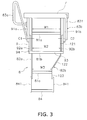
- FIG. 3 is a side view illustrating the ladder 8 and the platform 7 as seen from the left side
- FIG. 4 is a front view illustrating the ladder 8 and the platform 7 as seen from the front.
- the steps are depicted with dashed lines in FIG. 4 so that the positions of the steps can be understood.
- the expansion member 9 assumes the expanded posture in FIG. 3 and FIG. 4 .
- the ladder 8 has a plurality (e.g., three) of steps 81 a to 81 c, a front strut 82a, the rear strut 82b, and a supplementary step 84.
- the three steps 81 a to 81 c are horizontally disposed with intervals therebetween in the vertical direction, and are disposed from the top in order of the first step 81 a, the second step 81 b, and the third step 81 c.
- the second step 81 b corresponds to the at least one step in the present invention.
- the steps 81 a to 81 c are rectangular plates as seen in a plan view and extend in the front-back direction of the vehicle.
- the first and second steps 81 a and 81 b are longer in the vehicle front-back direction of the vehicle than the third step 81c.
- respective lengths W1 and W2 of the first and second steps 81 a and 81 b in the vehicle front-back direction are approximately 430 mm to 480 mm while a length W3 of the third step 81 c in the vehicle front-back direction is approximately 300 mm to 350 mm.
- lengths D1 to D3 in the vehicle width direction of the first to third steps 81 a to 81 c are approximately the same, and while not limited in particular are in the range of 100 mm to 140 mm.
- the steps 81 a to 81 c protrude in the vehicle width direction. Specifically, the steps 81 a to 81 c protrude in the direction toward the left (toward the right in FIG. 4 ). That is, the second step 81 b protrudes further to the left than the first step 81 a, and the third step 81 c protrudes further to the left than the second step 81 b.
- the first step 81 a protrudes further to the left than the platform 7. Protrusion amounts L1 to L3 of the respective first to third steps 81 a to 81 c are approximately the same.
- the protrusion amount L1 of the first step 81 a is the distance in the vehicle width direction between the left edge (right edge in FIG. 4 ) of the first step 81 a and the left edge of the platform 7.
- the protrusion amount L2 of the second step 81 b is the distance in the vehicle width direction between the left edge of the second step 81 b and the left edge of the first step 81 a.
- the protrusion amount L3 of the third step 81c is the distance in the vehicle width direction between the left edge of the third step 81c and the left edge of the second step 81 b. While not limited in particular, the protrusion amounts L1 to L3 of the first to third steps 81 a to 81 c are preferably in the range of 50 mm to 65 mm.
- the front strut 82a and the rear strut 82b extend in the vertical direction and are provided with an interval therebetween in the vehicle front-back direction.
- the first to third steps 81 a to 81c extend between the front strut 82a and the rear strut 82b.
- the front strut 82a is a plate-like member and extends vertically as seen in a side view.
- the rear strut 82b has an upper part 121, a middle part 122, and a lower part 123 in order from the top.
- the first step 81 a and the second step 81 b are fixed to the upper part 121 and the third step 81 c is fixed to lower part 123.
- the upper part 121 extends vertically downward from the platform 7.
- the middle part 122 extends downward and toward the front from the lower end of the upper part 121. Specifically, the middle part 122 is inclined so that the upper end thereof is positioned further to the rear than the lower end.
- the lower part 123 extends vertically downward from the lower end of the middle part 122. Specifically, the lower part 123 is positioned further toward the front than the upper part 121. Since the front strut 82a extends vertically downward, the first and second steps 81 a and 81c extend further to the rear than the third step 81c.
- a pair of elastic strips 841 that extend vertically downward is attached to the lower end parts of the front strut 82a and the rear strut 82b.
- the supplementary step 84 that extends in the vehicle front-back direction is provided so as to join the lower end parts of the elastic strips 841 together.
- the supplementary step 84 is shorter in the vehicle front-back direction than the first step 81 a and the second step 81 b, and preferably has approximately the same dimensions as the third step 81 c as seen in a plan view.
- the supplementary step 84 protrudes further to the left than the third step 81 c.
- a protrusion amount L4 of the supplementary step 84 is approximately the same as the protrusion amounts L1 to L3 of the steps 81 a to 81 c.
- the protrusion amount L4 of the supplementary step 84 is the distance in the vehicle width direction between the left edge (right edge in FIG. 4 ) of the supplementary step 84 and the left edge of the third step 81 c.
- the expansion member 9 is a member for expanding the distance D2 in the vehicle width direction of the second step 81 b of the ladder 8.
- the expansion member 9 has a front fixed part (example of fixed part) 91 a, a rear fixed part (example of fixed part) 91 b, a front arm part (example of arm part) 92a, a rear arm part (example of arm part) 92b, and a flat part 93.
- the front arm part 92a, the rear arm part 92b, and the flat part 93 are formed in an integrated manner.
- the front fixed part 91 a and the rear fixed part 91 b extend downward from the lower surface of the platform 7.
- the front fixed part 91 a extends along the front strut 82a in front of the front strut 82a.
- An interval is formed between the front fixed part 91 a and the front strut 82a.
- the rear fixed part 91 b extends along the rear strut 82b to the rear of the rear strut 82b.
- An interval is formed between the rear fixed part 91 b and the rear strut 82b.
- the front arm part 92a is coupled to the lower end part of the front fixed part 91 a in a swingable manner around a first swing shaft C1
- the rear arm part 92b is coupled to the lower end part of the rear fixed part 91 b in a swingable manner around a second swing shaft C2.
- the flat part 93 extends between the distal end part of the front arm part 92a and the distal end part of the rear arm part 92b. That is, the flat part 93 which has a rectangular shape as seen in a plan view extends in the vehicle front-back direction.
- the front end of the flat part 93 is coupled to the distal end part of the front arm part 92a, and the rear end of the flat part 93 is coupled to the distal end part of the rear arm part 92b.
- the length of the flat part 93 in the vehicle front-back direction is slightly longer than the length W2 of the second step 81 b.
- the front arm part 92a, the rear arm part 92b, and the flat part 93 are formed in an integrated manner. These components are referred to collectively as a body section 94 hereinbelow.
- the body section 94 is able to swing with respect to the front fixed part 91 a and the rear fixed part 91 b.
- the expansion member 9 is able to assume the expanded posture and the retracted posture by swinging the body section 94. Specifically, the expansion member 9 assumes the state illustrated in FIGS. 2 , 3 and 4 when in the expanded posture. That is, the expansion member 9 abuts the second step 81 b and protrudes in the vehicle width direction when assuming the expanded posture. Specifically, the expansion member 9 is positioned on the left side of the second step 81 b so that the flat part 93 abuts the second step 81 b.
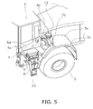
- the expansion member 9 assumes the retracted posture illustrated in FIGS. 5 and 6 from the expanded posture illustrated in FIG. 4 by swinging the body section 94 in the anticlockwise direction as indicated by the arrow.
- the flat part 93 is retracted from the left side of the second step 81 b when the expansion member 9 assumes the retracted posture.
- the flat part 93 is positioned below the platform 7 when the expansion member 9 assumes the retracted posture.
- a first handrail member 83a is provided on the front fixed part 91 a
- a second handrail member 83b is provided on the rear fixed part 91 b.
- the first and second handrail members 83a and 83b are used by the operator to ascend and descend the ladder 8.
- the second handrail member 83b has a vertical part 831 that extends vertically.
- the vertical part 831 is positioned to the left of the rear strut 83b.
- the upper end of the second handrail member 83b is positioned below the platform 7.
- FIG. 7 is a view of the rear body part as seen from the left side of the vehicle with a vehicle body cover 10 ( FIG. 1 ) to the rear of the cab 6 and the rear wheel fender 5a ( FIG. 1 ) removed.
- the vehicle body cover 10 is a member that demarcates an engine room 101 for housing the engine 15. Specifically, the vehicle body cover 10 covers the engine 15. As illustrated in FIG. 7 , the engine 15, a cooling unit 16 disposed to the rear of the engine 15, a supporting mechanism 17, and an exhaust gas post-treatment device 18 mounted on the supporting mechanism 17 above the engine 15 are disposed in a rear part of the rear body part. An operating fluid tank 19 is disposed between the cab 6 and the engine 15.
- the engine 15 is a so-called vertical mounted engine and is disposed so that a crankshaft extends in the vehicle front-back direction.
- the engine 15 is supported on the vehicle frame 2 via a rubber mount.
- a turbo charger 22 that supercharges the air intake due to the exhaust gas is provided on the left side of the engine 15.
- the turbo charger 22 is provided so that an exhaust gas outlet faces to the rear.
- a connecting pipe 23 is provided between the turbo charger 22 and the exhaust gas post-treatment device 18.
- a flexible intake pipe 24 made of plastic is provided between the turbo charger 22 and the air cleaner 13. A difference in vibration between the engine 15 and the air cleaner 13 is absorbed by the intake pipe 24.
- the exhaust gas post-treatment device 18 is equipped with a diesel particulate filter device 45, a connecting pipe 48, and a nitrogen oxide reduction catalyst device 47 in order from the exhaust gas upstream side of the engine 15 (hereinafter referred to simply as "upstream side").
- a urea aqueous solution injection device 46 is attached to the connecting pipe 48.
- the diesel particulate filter device 45 collects particulate matter such as smoke and the like in the exhaust gas, and is mounted on the rear part of a base plate 28 of the supporting mechanism 17.
- the urea aqueous solution injection device 46 emits a urea aqueous solution sucked up by a pump that is not illustrated from a urea aqueous solution tank that is not illustrated, and adds the urea aqueous solution to the exhaust gas as a reducing agent.
- the added urea aqueous solution is hydrolyzed to become ammonia, and the ammonia is fed with the exhaust gas through the connecting pipe 48 to the nitrogen oxide reduction catalyst device 47.
- the ammonia from the urea aqueous solution injection device 46 is used as a reducing agent to purify by reduction the nitrogen oxides in the exhaust gas in the nitrogen oxide reduction catalyst device 47.
- the nitrogen oxide reduction catalyst device 47 is mounted on the front part of the base plate 28 of the supporting mechanism 17 in the same way as the diesel particulate filter device 45.
- the diesel particulate filter device 45 and the nitrogen oxide reduction catalyst device 47 are fixed to the base plate 28 with each of the separate attachment plates.
- the diesel particulate filter device 45 and the nitrogen oxide reduction catalyst device 47 are disposed parallel to each other. Specifically, the diesel particulate filter device 45 and the nitrogen oxide reduction catalyst device 47 are both cylindrical and the center axes thereof are disposed so as to extend in the left-right direction and are parallel to each other.
- An exhaust gas inlet 45a is provided on the left edge part of the diesel particulate filter device 45, and an opening of the exhaust gas inlet 45a faces toward the rear.
- An exhaust gas outlet 45b is provided on the right edge part of the diesel particulate filter device 45, and an opening of the exhaust gas outlet 45b faces toward the front.
- An exhaust gas inlet 47a is provided on the left edge part of the nitrogen oxide reduction catalyst device 47, and an opening of the exhaust gas inlet 47a faces toward the rear.
- An exhaust gas outlet 47b is provided on the right edge part of the nitrogen oxide reduction catalyst device 47, and an opening of the exhaust gas outlet 47b faces toward the rear and obliquely upward.
- the connecting pipe 48 is disposed between the exhaust gas outlet 45b of the diesel particulate filter device 45 and the exhaust gas inlet 47a of the nitrogen oxide reduction catalyst device 47.
- the connecting pipe 48 has a first bend section 48a, a linear section 48b, and a second bend section 48c, and the entire connecting pipe 48 forms an S shape.
- the first bend section 48a is located near the exhaust gas outlet 45b of the diesel particulate filter device 45
- the second bend section 48c is located near the exhaust gas inlet 47a of the nitrogen oxide reduction catalyst device 47.
- the linear section 48b is located between the first bend section 48a and the second bend section 48c and is disposed parallel to the diesel particulate filter device 45 and the nitrogen oxide reduction catalyst device 47.
- the urea aqueous solution injection device 46 is provided on the first bend section 48a and emits a urea aqueous solution into the connecting pipe 48.
- the emitted urea aqueous solution becomes evenly mixed with the exhaust gas while passing through the long linear section 48b.
- the air cleaner 13 and a disposition thereof are explained with reference to FIGS. 2 and 9 .
- the air cleaner 13 is disposed outside of the engine room, that is, to the outside of the vehicle body cover 10.
- the air cleaner 13 is disposed above and to the rear of the expansion member 9 when the expansion member assumes the expanded posture.
- the air cleaner 13 is disposed in a position to allow the operator to reach the air cleaner 13 with his hands while standing on the second step 81b of the ladder 8.
- the air cleaner 13 is provided on the upper part of the rear wheel fender 5a.
- the air cleaner 13 is mounted on the horizontal portion of the fender front part 5b.
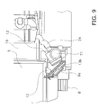
- FIG. 9 is a plan view of the air cleaner 13 and a portion that pertains to the air cleaner 13 with the vehicle body cover 10 and the air cleaner cover 70 removed.
- the air cleaner 13 is cylindrical and is provided with a cap 71 that covers an air intake mouth 13a on the upper part of the air cleaner 13, and with an openable and closable lid 13b on the front part of the air cleaner 13.
- a filter 72 is provided in an attachable and detachable manner inside the air cleaner 13.
- the air cleaner cover 70 covers most of the air cleaner 13 excluding the front edge part to which the air intake mouth 13a, the cap 71, and the lid 13b are attached.
- the filter 72 can be maintained and exchanged by opening the lid 13b and pulling the filter 72 out obliquely toward the front.
- the air cleaner 13 is disposed on the upper part of the fender front part 5b of the rear wheel fender 5a to the rear of the cab 6. More specifically, the front part of the air cleaner 13 is located to the rear of the ladder 8 and to the left of the rear end part of the cab 6, and the rear part of the air cleaner 13 is located to the left of the front part of the operating fluid tank 19.
- a center axis C of the air cleaner 13 is substantially horizontal and is slanted with respect to the center axis extending to the front and rear of the vehicle so that the front part of the air cleaner 13 is further away from the cab 6 than the rear part as illustrated in FIG. 8 .
- the filter 72 can be removed toward the front along the center axis C.
- the stopper 6d for limiting the maximum opening degree of the door 6c is provided on the cab 6, and the front part of the air cleaner 13 is positioned so as to not obstruct the door 6c even when the door 6c is opened to the greatest amount to abut the stopper 6d.
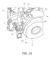
- the operator can stand on the flat part 93 and the second step 81 b of the ladder 8 and open the lid 13b of the air cleaner 13 to easily perform maintenance work or exchange work of the filter 72 as illustrated in FIG. 10 .
- air is introduced from the air cleaner 13 and fed into the engine 15 through the intake pipe 24 and the turbo charger 22.
- Exhaust gas from the engine 15 is introduced through the connecting pipe 23 into the exhaust gas post-treatment device 18 after driving the turbo charger 22.
- Particulate matter such as smoke is collected by the diesel particulate filter device 45 in the exhaust gas post-treatment device 18.
- the exhaust gas is then introduced into the urea aqueous solution injection device 46.
- Urea aqueous solution is emitted into the exhaust gas in the urea aqueous solution injection device 46.
- the emitted urea aqueous solution mixes with the exhaust gas inside the connecting pipe 48. Consequently, the urea aqueous solution is hydrolyzed by the heat of the exhaust gas and water vapor in the exhaust gas to become ammonia.
- the ammonia generated in this way is fed with the exhaust gas through the connecting pipe 48 to the nitrogen oxide reduction catalyst device 47.
- the ammonia is used as the reducing agent to purify by reduction the nitrogen oxides in the exhaust gas in the nitrogen oxide reduction catalyst device 47.
- the difference between the two vibrations can be sufficiently absorbed since the relatively long flexible pipe sections 54c, 54d are formed in the extending section 54a of the connecting pipe 23. Therefore, the vibration of the engine 15 can be suppressed.
- the operator When removing the filter 72 from the air cleaner 13, the operator first swings the body section 94 of the expansion member 9 to make the expansion member 9 assume the expanded posture as illustrated in FIG. 10 . The operator then stands on the second step 81b of the ladder 8 and the flat part 93 of the expansion member 9 and opens the lid 13b of the air cleaner 13. The filter 72 of the air cleaner 13 may be pulled out toward the front along the center axis C of the air cleaner 13. At this time, since the air cleaner 13 is inclined so that the front side thereof is further away from the cab 6 than the rear side thereof, the work to remove the filter 72 is easy to perform. When the maintenance work is completed, the operator swings the body section 94 of the expansion member 9 so that the expansion member 9 assumes the retracted posture as illustrated in FIGS. 5 and 6 .
- the air cleaner 13 Since the air cleaner 13 is disposed outside of the vehicle body cover 10 and above and to the rear of the ladder 8, the top plate of the engine room does not become higher and the diesel particulate filter device 45 and the nitrogen oxide reduction catalyst device 47 can be disposed above the engine 15. Therefore, a reduction in visibility to the rear can be avoided even if the nitrogen oxide reduction catalyst device 47 is added to the exhaust gas post-treatment device 18.
- the air cleaner 13 Since the air cleaner 13 is disposed above and to the rear of the ladder 8, maintenance work on the air cleaner 13 can be performed by the operator while standing on the ladder and the maintenance work can be performed easily.
- the expansion member 9 assumes the expanded posture, the flat part 93 of the expansion member 9 abuts the second step 81 b at the left side of the second step 81 b.
- the operator is able to work while standing on the second step 81 b and the flat part 93 and consequently is able to perform the maintenance work of the air cleaner 13 in a stable posture.
- the expansion member 9 assumes the retracted posture whereby the expansion member 9 does not become an obstruction while climbing up to and down from the cab 6.
- the second step 81 b is longer in the vehicle front-back direction than the third step 81c. According to this configuration, the operator is able to perform the maintenance work on the air cleaner 13 while maintaining a stable posture on the second step 81 b.
- the air cleaner 13 is configured to allow the filter 72 to be pulled out toward the ladder 8, and the air cleaner 13 is inclined so that a side from which the filter 72 is pulled out is further away from the cab 6 than the opposite side. Therefore, the operator can easily pull out the filter 72 while standing on the second step 81 b if the ladder 8 and maintenance work can be conducted more easily.
- the expansion member 9 is attached to the platform 7 and not to the ladder 8 and thus the expansion member 9 functions effectively even if the ladder 8 is deformed due to a collision and the like.
- the upper part 121 to which the first and second steps 81 a and 81 b are fixed is positioned further to the rear than the lower part 123 to which the third step 81 c is fixed. That is, the second step 81 b extends further to the rear than the third step 81 c and the operator is able to perform the maintenance work in a position closer to the air cleaner 13.
- the vertical part 831 of the second handrail member 83b extends vertically on the left side of the rear strut 82b.
- the ladder 8 has the three steps including the first to third steps 81 a to 81c in the above embodiment, the ladder 8 is not limited in particular and may have four or more steps or two steps or less.
- the air cleaner 13 may be fixed to another member so long as the air cleaner 13 is positioned above and to the rear of the ladder.
- the air cleaner 13 may be fixed to the upper part of an integrated rear wheel fender.
- the ladder 8 and the air cleaner 13 may be provided on the right side of the cab 6.
- the attachment component is not limited in particular, and the expansion member 9 may be attached to the ladder 8, for example.
- the expansion member 9 has the flat part 93, the front arm part 92a, and the rear arm part 92b, and the distal end part of the front arm part 92a may be attached to the front strut 82a of the ladder 8 in a swingable manner, and the distal end part of the rear arm part 92b may be attached to the rear strut 82b of the ladder 8.
- the fixed part of the expansion member 9 may be omitted.
- the expansion member 9 is configured to expand the length of the second step 81 b in the vehicle width direction
- the expansion member 9 is not limited to this configuration.
- the expansion member 9 may be configured to expand the length of the first step 81 a in the vehicle width direction.
- the flat part 93 is positioned to the left side of the first step 81 a so as to abut the first step 81 a.
- the first step 81 a corresponds to the at least one step in the present invention.
- the expansion member 9 may be provided as two expansion members 9 and configured so as to expand the lengths of both the first step 81 a and the second step 81 b in the vehicle width direction.
- the first step 81 a and the second step 81 b correspond to the at least one step in the present invention. That is, more than one of the at least one step may be provided.
- the expansion member 9 is able to assume the expanded posture and the retracted posture in the above embodiment, the expansion member 9 is not limited in this way.
- the expansion member 9 may be configured so as to assume only the expanded posture.
- the expansion member 9 may be attached, for example, to the platform 7 or the ladder 8 in a detachable manner. The expansion member 9 then assumes the expanded posture while the expansion member 9 is attached.
Landscapes
- Engineering & Computer Science (AREA)
- Mechanical Engineering (AREA)
- General Engineering & Computer Science (AREA)
- Chemical & Material Sciences (AREA)
- Combustion & Propulsion (AREA)
- Civil Engineering (AREA)
- Mining & Mineral Resources (AREA)
- Structural Engineering (AREA)
- Transportation (AREA)
- Body Structure For Vehicles (AREA)
- Cooling, Air Intake And Gas Exhaust, And Fuel Tank Arrangements In Propulsion Units (AREA)
- Component Parts Of Construction Machinery (AREA)
- Exhaust Gas After Treatment (AREA)
Description
- The present invention relates to a wheel loader.
- An exhaust gas post-treatment device is mounted on a wheel loader. The exhaust gas post-treatment device includes a diesel particulate filter device that collects and removes particulate matter of smoke and the like included in the diesel engine exhaust gas. The diesel particulate filter device is mounted in a row with an air cleaner above the engine. A nitrogen oxide reduction catalyst device may also be provided to remove NOx from the exhaust gas. The nitrogen oxide reduction catalyst device is provided on the exhaust downstream side of the diesel particulate filter device.
- As described above, while the diesel particulate filter device is disposed with the air cleaner above the engine, the installation location of the nitrogen oxide reduction catalyst device becomes a problem if the nitrogen oxide reduction catalyst device is installed along with the diesel particulate filter device. Since the nitrogen oxide reduction catalyst device needs to be disposed on the exhaust downstream side of the diesel particulate filter device, generally the nitrogen oxide reduction catalyst device is mounted in a row with the air cleaner and the diesel particulate filter device above the engine if the nitrogen oxide reduction catalyst device is installed along with the diesel particulate filter device.
- However, a problem arises with the spatial relationship when the air cleaner, the diesel particulate filter device, and the nitrogen oxide reduction catalyst device are all disposed in a row above the engine. Therefore, although the disposition of a relatively light air cleaner above the diesel particulate filter device and the nitrogen oxide reduction catalyst device may be considered, the top plate of the engine room becomes higher in this case and visibility to the rear is reduced.
- Accordingly, a configuration has been proposed for a large-scale dump truck described in
Patent Document 1 in which an engine room is provided beside the cab and an air cleaner is disposed on the outside of the engine room. With such a configuration, visibility to the rear is not reduced when the air cleaner is disposed on the upper portion of the engine room. - Patent Document 1: Japanese Patent Laid-open No.
2003-335268 - However, since the engine room is disposed to the rear of the cab in a wheel loader, visibility to the rear may become reduced if the configuration described in
Patent Document 1 is applied as-is to the wheel loader. Further, the air cleaner needs to be disposed to allow for ease of maintenance work since the filter inside the air cleaner requires regular cleaning and exchanging at certain time periods. - An object of the present invention is to prevent a reduction in visibility to the rear and to enable ease of maintenance work in a wheel loader.
- A wheel loader according to a first aspect of the present invention is provided with a cab, a ladder, an expansion member, a vehicle body cover, an engine, and an air cleaner. The cab is provided with a driver seat inside the cab. The ladder is provided at a side of the cab. The ladder has a plurality of steps disposed with intervals therebetween. The expansion member assumes an expanded posture. The expansion member abuts at least one step and protrudes in the vehicle width direction when in the expanded posture. The vehicle body cover is disposed to the rear of the cab and demarcates an engine room. The engine is disposed inside the engine room. The air cleaner includes therein a filter that is exchangeable and cleans air supplied to the engine. The air cleaner is disposed outside of the vehicle body cover. The air cleaner is disposed above and to the rear of the expansion member when the expansion member assumes the expanded posture.
- The air cleaner in the wheel loader is provided on the outside of the vehicle body cover and is not provided in the engine room. According to this configuration, since the air cleaner is disposed outside of the engine room, a top plate of the engine room does not need to be made higher even if an exhaust gas post-treatment device is installed above the engine inside the engine room. Therefore, reduction in visibility to the rear can be avoided despite the installation of the exhaust gas post-treatment device.
- Moreover, since the air cleaner is disposed above and to the rear of the expansion member while the expansion member assumes the expanded posture, maintenance work on the air cleaner can be performed by the operator while on the ladder and the maintenance work can be performed easily. The expansion member abuts at least one step when the expansion member assumes the expanded posture. As a result, the operator is able to work while standing on the at least one step and the expansion member. In this way, the operator is able to perform the air cleaner maintenance work in a stable posture because the foothold for the operator is widened when working.
- The expansion member preferably assumes a retracted posture in which the expansion member is retracted from the at least one step. That is, the expansion member is able to assume the expanded posture and the retracted posture. According to this configuration, when the operator is not performing maintenance work, that is, when the ladder is used for climbing up to and down from the cab, the expansion member does not become an obstruction while climbing up to and down from the cab due to the retracted posture of the expansion member.
- The at least one step preferably has a length in the vehicle front-back direction greater than that of the other steps. According to this configuration, the operator is able to perform the maintenance work on the air cleaner while maintaining a stable posture.
- The air cleaner is preferably configured so that the filter can be pulled out toward the ladder and disposed so as to be inclined so that the pulling-out side of the filter is further away from the cab than the opposite side. According to this configuration, the operator is able to remove the filter easily while standing on the at least one step of the ladder.
- The wheel loader preferably is further provided with a platform disposed at the side of the cab. The expansion member is positioned under the platform in the retracted posture. According to this configuration, the expansion member does not become an obstruction when the operator uses the ladder for climbing up to and down from the cab due to the expansion member being positioned below the platform.
- The expansion member is preferably attached to the platform. According to this configuration, even if the ladder is deformed due to a collision, the expansion member can function effectively since the expansion member is attached to the platform and not to the ladder.
- The expansion member preferably has a fixed part, an arm part, and a flat part. The fixed part extends downward from the platform. The arm part couples to the lower end part of the fixed part is a swingable manner. The flat part extends from the arm part in the vehicle front-back direction. The flat part abuts the at least one step in the expanded posture. According to this configuration, the expansion member is able to selectively assume the expanded posture and the retracted posture by swinging the arm part with respect to the fixed part.
- The ladder preferably extends downward from the platform disposed at the side of the cab. A first step positioned at the top of the plurality of steps protrudes from the platform in the vehicle width direction. Steps other than the first step protrude in the vehicle width direction from one step above. A protrusion amount of each step is fixed.
- According to this configuration, the operator is able to ascend and descend the steps of the ladder smoothly, the expansion member being positioned in the retracted posture.
- The ladder preferably has a front strut and a rear strut that extend in the vertical direction and that are disposed away from each other in the vehicle front-back direction. The steps extend so as to cross between the front strut and the rear strut. The rear strut has an upper part and a lower part. The upper part of the rear strut has attached thereto a first step positioned at the top and a second step positioned second from the top among the plurality of steps. The lower part of the rear strut has another step attached thereto and the lower part is positioned further toward the front than the upper part.
- According to this configuration, the first and second steps are attached to the upper part of the rear strut and the upper part of the rear strut is positioned further to the rear than the lower part. As a result, the first and second steps extend further to the rear than the other steps and the operator is able to perform the maintenance work in a position near the air cleaner. In this case, the at least one step corresponds to the first step or the second step.
- The rear strut preferably further has a middle part that couples the upper part and the lower part. The middle part is inclined rearward in an upward direction as seen in a side view.
- The wheel loader preferably further has a handrail member provided along the rear strut. The handrail member has a vertical part that extends vertically. The vertical part is positioned to the outside of the rear strut in the vehicle width direction. According to this configuration, since the vertical part of the handrail member is positioned to the outside of the rear strut in the vehicle width direction, the operator is able to perform the maintenance work while applying his weight onto the vertical part, and consequently is able to perform the maintenance work of the air cleaner while maintaining a more stable posture.
- An upper edge of the handrail member is preferably positioned below the platform disposed at the side of the cab. According to this configuration, the operator will not trip over the handrail member while standing on the platform.
- The ladder preferably further has a supplementary step that is below the step positioned at the bottom and that hangs down with elastic strips. According to this configuration, the operator is able to easily climb up to the step positioned at the bottom among the plurality of steps described above, and easily climb down from the step positioned at the bottom to the ground. Since the supplementary step is disposed in a position near the ground, the supplementary step or the elastic strips may collide with an obstruction on the ground. However, the elastic strips for suspending the supplementary step do not undergo plastic deformation.
- The cab preferably has a cab body and a door. The rear part of the door is supported by the cab body. The door can be opened and closed toward the front. The air cleaner is disposed at a location that does not obstruct the door when the door is fully open.
- According to this configuration, the door is not obstructed by the air cleaner when the driver opens or closes the door to enter or exit the cab.
- The wheel loader preferably further includes an operating fluid tank disposed between the cab and the engine. The air cleaner is disposed at the side of the operating fluid tank.
- According to this configuration, since the air cleaner is disposed outside of the engine room as described above, a reduction in visibility to the rear is avoided even if the exhaust gas post-treatment device is provided, and the maintenance work on the air cleaner can be performed easily.
- The wheel loader is preferably provided with a rear wheel fender disposed above a rear wheel. The air cleaner is fixed to an upper part of the rear wheel fender.
- According to this configuration, since the air cleaner is disposed outside of the engine room as described above, a reduction in visibility to the rear is avoided even if the exhaust gas post-treatment device is provided, and the maintenance work on the air cleaner can be performed easily as described above.
- According to the present invention, a reduction in visibility to the rear is prevented and the maintenance work on the air cleaner can be performed easily.
-
-
FIG. 1 is an external perspective view of a wheel loader. -
FIG. 2 is an external perspective partial view from the left front of the wheel loader ofFIG. 1 . -
FIG. 3 is a side view of a ladder. -
FIG. 4 is a front view of a ladder. -
FIG. 5 is an external perspective partial view from the left front of the wheel loader. -
FIG. 6 is a front view of the ladder. -
FIG. 7 is a side partial view with the vehicle body cover of the wheel loader removed. -
FIG. 8 is a plan view of a disposition of the air cleaner. -
FIG. 9 illustrates a relationship between the air cleaner and a door. -
FIG. 10 illustrates an appearance of maintenance work on the air cleaner. - An embodiment of a wheel loader according to the present invention will be explained below with reference to the drawings.
FIG. 1 is a perspective view of a wheel loader as seen from the left rear. In the following description, "right," "left," "up," and "down" indicate directions relative to a state of looking forward from the operating cabin, and "vehicle width direction" and "left-right direction" have the same meaning. Further, "width" signifies a length in the left-right direction. - A
wheel loader 1 includes avehicle body frame 2, a work implement 3,front wheels 4,rear wheels 5, and acab 6 as illustrated inFIG. 1 . Thewheel loader 1 is capable of traveling due to the rotation of thefront wheels 4 and therear wheels 5, and desired work can be conducted using the work implement 3. - The
vehicle body frame 2 includes a front body part and a rear body part, and the front body part and the rear body part are connected to each other to allow for swinging in the left-right direction. The work implement 3 and thefront wheels 4 are provided on the front body part. Therear wheels 5 and thecab 6 are provided on the rear body part. An operatingcabin 6a, various operating members and operating panels are provided inside thecab 6. The work implement 3 is disposed at the front of the front body part and includes abucket 3a, abucket cylinder 3b and the like.Fenders front wheels 4 and therear wheels 5. -
FIG. 2 is a perspective view of an area in the vicinity of the air cleaner as seen from the right front. Anexpansion member 9 assumes an expanded posture inFIG. 2 . As illustrated inFIG. 2 , therear wheel fender 5a has a fenderfront part 5b and a fenderrear part 5c. The fenderfront part 5b is configured by a horizontal portion and a sloped portion that slopes forward and downward from the horizontal portion. The fenderrear part 5c is formed in an arced shape as seen from the side and covers the upper part and the upper rear part of therear wheel 5. Amud guard 5d extends downward from the front edge of the fenderfront part 5b so as to cover the front of therear wheel 5. More specifically, themud guard 5d is formed along arear strut 82b of aladder 8 to be described below. - The
cab 6 has acab body 6b and adoor 6c. Thedoor 6c is supported at a rear edge part by a hinge on thecab body 6b, and a front edge part is able to be opened and closed. The maximum degree of opening of thedoor 6c is limited by astopper 6d provided on the outside of thecab body 6b. - A
platform 7 is disposed at the left side of thecab 6. More specifically, theplatform 7 extends to the left from a lower end part of thecab 6. As a result, the operator can easily climb up and down theladder 8 since a standing space is secured on the outside of thedoor 6c. Theplatform 7 is attached to thevehicle frame 2. - The
ladder 8 is provided at the left side of thecab 6 to allow the operator to climb up to and down from thecab 6. More specifically, theladder 8 extends downward from theplatform 7 and is disposed in front of therear wheel fender 5a. -
FIG. 3 is a side view illustrating theladder 8 and theplatform 7 as seen from the left side, andFIG. 4 is a front view illustrating theladder 8 and theplatform 7 as seen from the front. The steps are depicted with dashed lines inFIG. 4 so that the positions of the steps can be understood. Theexpansion member 9 assumes the expanded posture inFIG. 3 andFIG. 4 . As illustrated inFIGS. 3 and4 , theladder 8 has a plurality (e.g., three) ofsteps 81 a to 81 c, afront strut 82a, therear strut 82b, and asupplementary step 84. The threesteps 81 a to 81 c are horizontally disposed with intervals therebetween in the vertical direction, and are disposed from the top in order of thefirst step 81 a, thesecond step 81 b, and thethird step 81 c. Thesecond step 81 b corresponds to the at least one step in the present invention. Thesteps 81 a to 81 c are rectangular plates as seen in a plan view and extend in the front-back direction of the vehicle. The first andsecond steps third step 81c. For example, while not limited in particular, respective lengths W1 and W2 of the first andsecond steps third step 81 c in the vehicle front-back direction is approximately 300 mm to 350 mm. Moreover, lengths D1 to D3 in the vehicle width direction of the first tothird steps 81 a to 81 c are approximately the same, and while not limited in particular are in the range of 100 mm to 140 mm. - As illustrated in
FIG. 4 , thesteps 81 a to 81 c protrude in the vehicle width direction. Specifically, thesteps 81 a to 81 c protrude in the direction toward the left (toward the right inFIG. 4 ). That is, thesecond step 81 b protrudes further to the left than thefirst step 81 a, and thethird step 81 c protrudes further to the left than thesecond step 81 b. Thefirst step 81 a protrudes further to the left than theplatform 7. Protrusion amounts L1 to L3 of the respective first tothird steps 81 a to 81 c are approximately the same. The protrusion amount L1 of thefirst step 81 a is the distance in the vehicle width direction between the left edge (right edge inFIG. 4 ) of thefirst step 81 a and the left edge of theplatform 7. The protrusion amount L2 of thesecond step 81 b is the distance in the vehicle width direction between the left edge of thesecond step 81 b and the left edge of thefirst step 81 a. The protrusion amount L3 of thethird step 81c is the distance in the vehicle width direction between the left edge of thethird step 81c and the left edge of thesecond step 81 b. While not limited in particular, the protrusion amounts L1 to L3 of the first tothird steps 81 a to 81 c are preferably in the range of 50 mm to 65 mm. - As illustrated in
FIG. 3 , thefront strut 82a and therear strut 82b extend in the vertical direction and are provided with an interval therebetween in the vehicle front-back direction. The first tothird steps 81 a to 81c extend between thefront strut 82a and therear strut 82b. Thefront strut 82a is a plate-like member and extends vertically as seen in a side view. Therear strut 82b has anupper part 121, amiddle part 122, and alower part 123 in order from the top. Thefirst step 81 a and thesecond step 81 b are fixed to theupper part 121 and thethird step 81 c is fixed tolower part 123. Theupper part 121 extends vertically downward from theplatform 7. Themiddle part 122 extends downward and toward the front from the lower end of theupper part 121. Specifically, themiddle part 122 is inclined so that the upper end thereof is positioned further to the rear than the lower end. Thelower part 123 extends vertically downward from the lower end of themiddle part 122. Specifically, thelower part 123 is positioned further toward the front than theupper part 121. Since thefront strut 82a extends vertically downward, the first andsecond steps third step 81c. - A pair of
elastic strips 841 that extend vertically downward is attached to the lower end parts of thefront strut 82a and therear strut 82b. Thesupplementary step 84 that extends in the vehicle front-back direction is provided so as to join the lower end parts of theelastic strips 841 together. Thesupplementary step 84 is shorter in the vehicle front-back direction than thefirst step 81 a and thesecond step 81 b, and preferably has approximately the same dimensions as thethird step 81 c as seen in a plan view. - As illustrated in
FIG. 4 , thesupplementary step 84 protrudes further to the left than thethird step 81 c. A protrusion amount L4 of thesupplementary step 84 is approximately the same as the protrusion amounts L1 to L3 of thesteps 81 a to 81 c. The protrusion amount L4 of thesupplementary step 84 is the distance in the vehicle width direction between the left edge (right edge inFIG. 4 ) of thesupplementary step 84 and the left edge of thethird step 81 c. - As illustrated in
FIGS 3 and4 , theexpansion member 9 is a member for expanding the distance D2 in the vehicle width direction of thesecond step 81 b of theladder 8. Theexpansion member 9 has a front fixed part (example of fixed part) 91 a, a rear fixed part (example of fixed part) 91 b, a front arm part (example of arm part) 92a, a rear arm part (example of arm part) 92b, and aflat part 93. Thefront arm part 92a, therear arm part 92b, and theflat part 93 are formed in an integrated manner. - The front
fixed part 91 a and the rear fixedpart 91 b extend downward from the lower surface of theplatform 7. The frontfixed part 91 a extends along thefront strut 82a in front of thefront strut 82a. An interval is formed between the front fixedpart 91 a and thefront strut 82a. The rearfixed part 91 b extends along therear strut 82b to the rear of therear strut 82b. An interval is formed between the rear fixedpart 91 b and therear strut 82b. - The
front arm part 92a is coupled to the lower end part of the front fixedpart 91 a in a swingable manner around a first swing shaft C1, and therear arm part 92b is coupled to the lower end part of the rear fixedpart 91 b in a swingable manner around a second swing shaft C2. Theflat part 93 extends between the distal end part of thefront arm part 92a and the distal end part of therear arm part 92b. That is, theflat part 93 which has a rectangular shape as seen in a plan view extends in the vehicle front-back direction. The front end of theflat part 93 is coupled to the distal end part of thefront arm part 92a, and the rear end of theflat part 93 is coupled to the distal end part of therear arm part 92b. The length of theflat part 93 in the vehicle front-back direction is slightly longer than the length W2 of thesecond step 81 b. - As mentioned above, the
front arm part 92a, therear arm part 92b, and theflat part 93 are formed in an integrated manner. These components are referred to collectively as abody section 94 hereinbelow. Thebody section 94 is able to swing with respect to the front fixedpart 91 a and the rear fixedpart 91 b. Theexpansion member 9 is able to assume the expanded posture and the retracted posture by swinging thebody section 94. Specifically, theexpansion member 9 assumes the state illustrated inFIGS. 2 ,3 and4 when in the expanded posture. That is, theexpansion member 9 abuts thesecond step 81 b and protrudes in the vehicle width direction when assuming the expanded posture. Specifically, theexpansion member 9 is positioned on the left side of thesecond step 81 b so that theflat part 93 abuts thesecond step 81 b. - The
expansion member 9 assumes the retracted posture illustrated inFIGS. 5 and6 from the expanded posture illustrated inFIG. 4 by swinging thebody section 94 in the anticlockwise direction as indicated by the arrow. As illustrated inFIGS. 5 and6 , theflat part 93 is retracted from the left side of thesecond step 81 b when theexpansion member 9 assumes the retracted posture. Specifically, theflat part 93 is positioned below theplatform 7 when theexpansion member 9 assumes the retracted posture. - As illustrated in
FIG. 3 , afirst handrail member 83a is provided on the front fixedpart 91 a, and asecond handrail member 83b is provided on the rear fixedpart 91 b. The first andsecond handrail members ladder 8. Thesecond handrail member 83b has avertical part 831 that extends vertically. Thevertical part 831 is positioned to the left of therear strut 83b. The upper end of thesecond handrail member 83b is positioned below theplatform 7. -
FIG. 7 is a view of the rear body part as seen from the left side of the vehicle with a vehicle body cover 10 (FIG. 1 ) to the rear of thecab 6 and therear wheel fender 5a (FIG. 1 ) removed. Thevehicle body cover 10 is a member that demarcates an engine room 101 for housing theengine 15. Specifically, the vehicle body cover 10 covers theengine 15. As illustrated inFIG. 7 , theengine 15, a coolingunit 16 disposed to the rear of theengine 15, a supportingmechanism 17, and an exhaust gaspost-treatment device 18 mounted on the supportingmechanism 17 above theengine 15 are disposed in a rear part of the rear body part. An operatingfluid tank 19 is disposed between thecab 6 and theengine 15. - The
engine 15 is a so-called vertical mounted engine and is disposed so that a crankshaft extends in the vehicle front-back direction. Theengine 15 is supported on thevehicle frame 2 via a rubber mount. - As illustrated in
FIG. 7 , aturbo charger 22 that supercharges the air intake due to the exhaust gas is provided on the left side of theengine 15. Theturbo charger 22 is provided so that an exhaust gas outlet faces to the rear. A connectingpipe 23 is provided between theturbo charger 22 and the exhaust gaspost-treatment device 18. Aflexible intake pipe 24 made of plastic is provided between theturbo charger 22 and theair cleaner 13. A difference in vibration between theengine 15 and theair cleaner 13 is absorbed by theintake pipe 24. - As illustrated in
FIG. 8 , the exhaust gaspost-treatment device 18 is equipped with a dieselparticulate filter device 45, a connectingpipe 48, and a nitrogen oxidereduction catalyst device 47 in order from the exhaust gas upstream side of the engine 15 (hereinafter referred to simply as "upstream side"). A urea aqueoussolution injection device 46 is attached to the connectingpipe 48. - The diesel
particulate filter device 45 collects particulate matter such as smoke and the like in the exhaust gas, and is mounted on the rear part of a base plate 28 of the supportingmechanism 17. The urea aqueoussolution injection device 46 emits a urea aqueous solution sucked up by a pump that is not illustrated from a urea aqueous solution tank that is not illustrated, and adds the urea aqueous solution to the exhaust gas as a reducing agent. The added urea aqueous solution is hydrolyzed to become ammonia, and the ammonia is fed with the exhaust gas through the connectingpipe 48 to the nitrogen oxidereduction catalyst device 47. The ammonia from the urea aqueoussolution injection device 46 is used as a reducing agent to purify by reduction the nitrogen oxides in the exhaust gas in the nitrogen oxidereduction catalyst device 47. The nitrogen oxidereduction catalyst device 47 is mounted on the front part of the base plate 28 of the supportingmechanism 17 in the same way as the dieselparticulate filter device 45. The dieselparticulate filter device 45 and the nitrogen oxidereduction catalyst device 47 are fixed to the base plate 28 with each of the separate attachment plates. - The diesel
particulate filter device 45 and the nitrogen oxidereduction catalyst device 47 are disposed parallel to each other. Specifically, the dieselparticulate filter device 45 and the nitrogen oxidereduction catalyst device 47 are both cylindrical and the center axes thereof are disposed so as to extend in the left-right direction and are parallel to each other. Anexhaust gas inlet 45a is provided on the left edge part of the dieselparticulate filter device 45, and an opening of theexhaust gas inlet 45a faces toward the rear. Anexhaust gas outlet 45b is provided on the right edge part of the dieselparticulate filter device 45, and an opening of theexhaust gas outlet 45b faces toward the front. Anexhaust gas inlet 47a is provided on the left edge part of the nitrogen oxidereduction catalyst device 47, and an opening of theexhaust gas inlet 47a faces toward the rear. Anexhaust gas outlet 47b is provided on the right edge part of the nitrogen oxidereduction catalyst device 47, and an opening of theexhaust gas outlet 47b faces toward the rear and obliquely upward. The connectingpipe 48 is disposed between theexhaust gas outlet 45b of the dieselparticulate filter device 45 and theexhaust gas inlet 47a of the nitrogen oxidereduction catalyst device 47. - As illustrated in
FIG. 8 , the connectingpipe 48 has afirst bend section 48a, alinear section 48b, and asecond bend section 48c, and the entire connectingpipe 48 forms an S shape. Thefirst bend section 48a is located near theexhaust gas outlet 45b of the dieselparticulate filter device 45, and thesecond bend section 48c is located near theexhaust gas inlet 47a of the nitrogen oxidereduction catalyst device 47. Thelinear section 48b is located between thefirst bend section 48a and thesecond bend section 48c and is disposed parallel to the dieselparticulate filter device 45 and the nitrogen oxidereduction catalyst device 47. - The urea aqueous
solution injection device 46 is provided on thefirst bend section 48a and emits a urea aqueous solution into the connectingpipe 48. The emitted urea aqueous solution becomes evenly mixed with the exhaust gas while passing through the longlinear section 48b. - The
air cleaner 13 and a disposition thereof are explained with reference toFIGS. 2 and9 . Theair cleaner 13 is disposed outside of the engine room, that is, to the outside of thevehicle body cover 10. Theair cleaner 13 is disposed above and to the rear of theexpansion member 9 when the expansion member assumes the expanded posture. Theair cleaner 13 is disposed in a position to allow the operator to reach theair cleaner 13 with his hands while standing on thesecond step 81b of theladder 8. Specifically, theair cleaner 13 is provided on the upper part of therear wheel fender 5a. Specifically, theair cleaner 13 is mounted on the horizontal portion of the fenderfront part 5b. - As illustrated in
FIG. 2 , except for a portion thereof, theair cleaner 13 is covered by an aircleaner cover 70 that is provided on the outside of thevehicle body cover 10.FIG. 9 is a plan view of theair cleaner 13 and a portion that pertains to theair cleaner 13 with thevehicle body cover 10 and the aircleaner cover 70 removed. - As illustrated in
FIGS. 2 ,8 , and9 , theair cleaner 13 is cylindrical and is provided with acap 71 that covers anair intake mouth 13a on the upper part of theair cleaner 13, and with an openable andclosable lid 13b on the front part of theair cleaner 13. Afilter 72 is provided in an attachable and detachable manner inside theair cleaner 13. The aircleaner cover 70 covers most of theair cleaner 13 excluding the front edge part to which theair intake mouth 13a, thecap 71, and thelid 13b are attached. Thefilter 72 can be maintained and exchanged by opening thelid 13b and pulling thefilter 72 out obliquely toward the front. - The disposition of the
air cleaner 13 is explained in detail below. - As illustrated in
FIG. 9 , theair cleaner 13 is disposed on the upper part of the fenderfront part 5b of therear wheel fender 5a to the rear of thecab 6. More specifically, the front part of theair cleaner 13 is located to the rear of theladder 8 and to the left of the rear end part of thecab 6, and the rear part of theair cleaner 13 is located to the left of the front part of the operatingfluid tank 19. A center axis C of theair cleaner 13 is substantially horizontal and is slanted with respect to the center axis extending to the front and rear of the vehicle so that the front part of theair cleaner 13 is further away from thecab 6 than the rear part as illustrated inFIG. 8 . As described above, thefilter 72 can be removed toward the front along the center axis C. - As described above, the
stopper 6d for limiting the maximum opening degree of thedoor 6c is provided on thecab 6, and the front part of theair cleaner 13 is positioned so as to not obstruct thedoor 6c even when thedoor 6c is opened to the greatest amount to abut thestopper 6d. - Due to the disposition of the
air cleaner 13 as described above, the operator can stand on theflat part 93 and thesecond step 81 b of theladder 8 and open thelid 13b of theair cleaner 13 to easily perform maintenance work or exchange work of thefilter 72 as illustrated inFIG. 10 . - As illustrated in
FIG. 7 , air is introduced from theair cleaner 13 and fed into theengine 15 through theintake pipe 24 and theturbo charger 22. Exhaust gas from theengine 15 is introduced through the connectingpipe 23 into the exhaust gaspost-treatment device 18 after driving theturbo charger 22. - Particulate matter such as smoke is collected by the diesel
particulate filter device 45 in the exhaust gaspost-treatment device 18. Next, the exhaust gas is then introduced into the urea aqueoussolution injection device 46. Urea aqueous solution is emitted into the exhaust gas in the urea aqueoussolution injection device 46. The emitted urea aqueous solution mixes with the exhaust gas inside the connectingpipe 48. Consequently, the urea aqueous solution is hydrolyzed by the heat of the exhaust gas and water vapor in the exhaust gas to become ammonia. The ammonia generated in this way is fed with the exhaust gas through the connectingpipe 48 to the nitrogen oxidereduction catalyst device 47. The ammonia is used as the reducing agent to purify by reduction the nitrogen oxides in the exhaust gas in the nitrogen oxidereduction catalyst device 47. - In the state in which the exhaust gas
post-treatment device 18 is assembled, theengine 15 and the transmission 20 are mounted on thevehicle body frame 2 via rubber mounts 21, and the exhaust gaspost-treatment device 18 is mounted directly onto thevehicle body frame 2 via the supportingmechanism 17. As a result, a difference arises between the vibrations from theengine 15 and the vibrations from the exhaust gaspost-treatment device 18 while the vehicle is being driven. - However, the difference between the two vibrations can be sufficiently absorbed since the relatively long flexible pipe sections 54c, 54d are formed in the extending section 54a of the connecting
pipe 23. Therefore, the vibration of theengine 15 can be suppressed. - Exchange work and cleaning of the
filter 72 are required at certain time periods in theair cleaner 13. At this time thefilter 72 is necessarily removed from theair cleaner 13. - When removing the
filter 72 from theair cleaner 13, the operator first swings thebody section 94 of theexpansion member 9 to make theexpansion member 9 assume the expanded posture as illustrated inFIG. 10 . The operator then stands on thesecond step 81b of theladder 8 and theflat part 93 of theexpansion member 9 and opens thelid 13b of theair cleaner 13. Thefilter 72 of theair cleaner 13 may be pulled out toward the front along the center axis C of theair cleaner 13. At this time, since theair cleaner 13 is inclined so that the front side thereof is further away from thecab 6 than the rear side thereof, the work to remove thefilter 72 is easy to perform. When the maintenance work is completed, the operator swings thebody section 94 of theexpansion member 9 so that theexpansion member 9 assumes the retracted posture as illustrated inFIGS. 5 and6 . - Since the
air cleaner 13 is disposed outside of thevehicle body cover 10 and above and to the rear of theladder 8, the top plate of the engine room does not become higher and the dieselparticulate filter device 45 and the nitrogen oxidereduction catalyst device 47 can be disposed above theengine 15. Therefore, a reduction in visibility to the rear can be avoided even if the nitrogen oxidereduction catalyst device 47 is added to the exhaust gaspost-treatment device 18. - Since the
air cleaner 13 is disposed above and to the rear of theladder 8, maintenance work on theair cleaner 13 can be performed by the operator while standing on the ladder and the maintenance work can be performed easily. When theexpansion member 9 assumes the expanded posture, theflat part 93 of theexpansion member 9 abuts thesecond step 81 b at the left side of thesecond step 81 b. As a result, the operator is able to work while standing on thesecond step 81 b and theflat part 93 and consequently is able to perform the maintenance work of theair cleaner 13 in a stable posture. When the operator is not performing maintenance work, that is, when theladder 8 is used for climbing up to and down from thecab 6, theexpansion member 9 assumes the retracted posture whereby theexpansion member 9 does not become an obstruction while climbing up to and down from thecab 6. - The
second step 81 b is longer in the vehicle front-back direction than thethird step 81c. According to this configuration, the operator is able to perform the maintenance work on theair cleaner 13 while maintaining a stable posture on thesecond step 81 b. - The
air cleaner 13 is configured to allow thefilter 72 to be pulled out toward theladder 8, and theair cleaner 13 is inclined so that a side from which thefilter 72 is pulled out is further away from thecab 6 than the opposite side. Therefore, the operator can easily pull out thefilter 72 while standing on thesecond step 81 b if theladder 8 and maintenance work can be conducted more easily. - The
expansion member 9 is attached to theplatform 7 and not to theladder 8 and thus theexpansion member 9 functions effectively even if theladder 8 is deformed due to a collision and the like. - The
upper part 121 to which the first andsecond steps lower part 123 to which thethird step 81 c is fixed. That is, thesecond step 81 b extends further to the rear than thethird step 81 c and the operator is able to perform the maintenance work in a position closer to theair cleaner 13. - The
vertical part 831 of thesecond handrail member 83b extends vertically on the left side of therear strut 82b. Thus, the operator is able to perform the maintenance work of theair cleaner 13 while applying his weight onto thevertical part 831, and consequently is able to perform the maintenance work of theair cleaner 13 while maintaining a more stable posture. - The present invention is not limited to the above embodiments and various changes and modifications may be made without departing from the spirit of the invention.
- While the
ladder 8 has the three steps including the first tothird steps 81 a to 81c in the above embodiment, theladder 8 is not limited in particular and may have four or more steps or two steps or less. - While the
air cleaner 13 is fixed to therear wheel fender 5a in the previous embodiment, theair cleaner 13 may be fixed to another member so long as theair cleaner 13 is positioned above and to the rear of the ladder. - While a case in which the
rear wheel fender 5a is divided into two parts and theair cleaner 13 is fixed to the fenderfront part 5b is described in the previous embodiment, theair cleaner 13 may be fixed to the upper part of an integrated rear wheel fender. - While a case in which the
ladder 8 and theair cleaner 13 are provided on the left side of thecab 6 is described in the previous embodiment, theladder 8 and theair cleaner 13 may be provided on the right side of thecab 6. - While the
expansion member 9 is attached to theplatform 7 in the above embodiment, the attachment component is not limited in particular, and theexpansion member 9 may be attached to theladder 8, for example. Specifically as illustrated in FIG. 17, theexpansion member 9 has theflat part 93, thefront arm part 92a, and therear arm part 92b, and the distal end part of thefront arm part 92a may be attached to thefront strut 82a of theladder 8 in a swingable manner, and the distal end part of therear arm part 92b may be attached to therear strut 82b of theladder 8. In this case, the fixed part of theexpansion member 9 may be omitted. - While the
expansion member 9 is configured to expand the length of thesecond step 81 b in the vehicle width direction, theexpansion member 9 is not limited to this configuration. For example as illustrated in FIG. 18, theexpansion member 9 may be configured to expand the length of thefirst step 81 a in the vehicle width direction. In this case, when theexpansion member 9 assumes the expanded posture, theflat part 93 is positioned to the left side of thefirst step 81 a so as to abut thefirst step 81 a. In this case, thefirst step 81 a corresponds to the at least one step in the present invention. Theexpansion member 9 may be provided as twoexpansion members 9 and configured so as to expand the lengths of both thefirst step 81 a and thesecond step 81 b in the vehicle width direction. In this case, thefirst step 81 a and thesecond step 81 b correspond to the at least one step in the present invention. That is, more than one of the at least one step may be provided. - While the
expansion member 9 is able to assume the expanded posture and the retracted posture in the above embodiment, theexpansion member 9 is not limited in this way. For example, theexpansion member 9 may be configured so as to assume only the expanded posture. In this case, theexpansion member 9 may be attached, for example, to theplatform 7 or theladder 8 in a detachable manner. Theexpansion member 9 then assumes the expanded posture while theexpansion member 9 is attached. -
- 1: Wheel loader
- 2: Vehicle body frame
- 6: Cab
- 5: Rear wheels
- 5a: Rear wheel fender
- 6a: Operating cabin
- 6b: Cab body
- 7: Platform
- 8: Ladder
- 81a: First step
- 81b: Second step
- 81c: Third step
- 82a: Front strut
- 82b: Rear strut
- 9: Expansion member
- 91a: Front fixed part
- 91b: Rear fixed part
- 92a: Front arm part
- 92b: Rear arm part
- 93: Flat part
- 121: Upper part
- 122: Middle part
- 123: Lower part
- 83b: Second handrail member
- 831: Vertical member
- 84: Supplementary step
- 841: Elastic strips
- 6c: Door
- 6d: Stopper
- 13: Air cleaner
- 13a: Air intake
- 13b: Lid
- 15: Engine
- 17: Supporting mechanism
- 18: Exhaust gas post-treatment device
- 19: Operating fluid tank
- 45: Diesel particulate collection and filter device
- 47: Selective reduction catalytic converter
Claims (13)
- A wheel loader comprising:a cab provided with a driver seat thereinside;a ladder having a plurality of steps disposed with intervals therebetween, the ladder provided at a side of the cab;an expansion member configured to assume an expanded posture of abutting at least one step and protruding in the vehicle width direction;a vehicle body cover disposed to the rear of the cab and demarcating an engine room;an engine disposed inside the engine room; andan air cleaner having therein a filter that is exchangeable, the air cleaner being disposed outside of the vehicle body cover, the air cleaner cleaning air supplied to the engine;wherein,when the expansion member assumes the expanded posture, the air cleaner is disposed above and to the rear of the expansion member.
- The wheel loader according to claim 1, wherein
the expansion member assumes a retracted posture in which the expansion member is retracted from the at least one step. - The wheel loader according to claim 1 or 2, wherein:the at least one step has a length in the vehicle front-back direction greater than that of the other steps.
- The wheel loader according to any one of claims 1 to 3, wherein:the air cleaner is configured so that the filter can be pulled out toward the ladder and disposed so as to be inclined so that a pulling-out side of the filter is further away from the cab than the opposite side.
- The wheel loader according to claim 2, further comprising:a platform disposed at the side of the cab, whereinthe expansion member is positioned under the platform in the retracted posture.
- The wheel loader according to claim 5, wherein:the expansion member is attached to the platform.
- The wheel loader according to claim 6, wherein:the expansion member has:a fixed part extending downward from the platform;an arm part coupled to a lower end part of the fixed part in a swingable manner; anda flat part extending from the arm part in the vehicle front-back direction and abutting the at least one step in the expanded posture.
- The wheel loader according to any one of claims 1 to 7, wherein:the ladder extends downward from a platform disposed at the side of the cab;a first step positioned at the top of the plurality of steps protrudes from the platform in the vehicle width direction;steps other than the first step protrude in the vehicle width direction with respect to one step thereabove; anda protrusion amount of the steps is fixed.
- The wheel loader according to any one of claims 1 to 8, wherein:the ladder has a front strut and a rear strut that extend in the vertical direction and that are disposed away from each other in the vehicle front-back direction;the steps extend so as to cross between the front strut and the rear strut; andthe rear strut has an upper part to which a first step positioned at the top and a second step positioned second from the top among the plurality of steps are attached, and a lower part to which another step is attached, the lower part being positioned further toward the front than the upper part.
- The wheel loader according to claim 9, wherein:the rear strut further has a middle part that couples the upper part and the lower part; andthe middle part is inclined rearward in an upward direction as seen in a side view.
- The wheel loader according to claim 9 or 10, further comprising:a handrail member provided along the rear strut; wherein,the handrail member has a vertical part that extends vertically; andthe vertical part is positioned to the outside in the vehicle width direction of the rear strut.
- The wheel loader according to claim 11, wherein:an upper edge of the handrail member is positioned below the platform installed at the side of the cab.
- The wheel loader according to any one of claims 1 to 12, wherein:the ladder further has a supplementary step that is below the step positioned at the bottom and that hangs down with elastic strips.
Applications Claiming Priority (2)
| Application Number | Priority Date | Filing Date | Title |
|---|---|---|---|
| JP2013164759 | 2013-08-08 | ||
| PCT/JP2014/070593 WO2015020036A1 (en) | 2013-08-08 | 2014-08-05 | Wheel loader |
Publications (3)
| Publication Number | Publication Date |
|---|---|
| EP2873777A1 true EP2873777A1 (en) | 2015-05-20 |
| EP2873777A4 EP2873777A4 (en) | 2016-01-06 |
| EP2873777B1 EP2873777B1 (en) | 2016-11-23 |
Family
ID=52461367
Family Applications (1)
| Application Number | Title | Priority Date | Filing Date |
|---|---|---|---|
| EP14833566.4A Active EP2873777B1 (en) | 2013-08-08 | 2014-08-05 | Wheel loader |
Country Status (5)
| Country | Link |
|---|---|
| US (1) | US9657456B2 (en) |
| EP (1) | EP2873777B1 (en) |
| JP (1) | JP5982501B2 (en) |
| CN (1) | CN104520514B (en) |
| WO (1) | WO2015020036A1 (en) |
Cited By (1)
| Publication number | Priority date | Publication date | Assignee | Title |
|---|---|---|---|---|
| EP3351460A4 (en) * | 2016-12-08 | 2018-11-14 | Komatsu Ltd. | Front fender and wheel loader |
Families Citing this family (8)
| Publication number | Priority date | Publication date | Assignee | Title |
|---|---|---|---|---|
| JP6297905B2 (en) * | 2014-04-22 | 2018-03-20 | 日立建機株式会社 | Construction machinery |
| EP2985166B1 (en) * | 2014-08-14 | 2017-08-02 | CNH Industrial Italia S.p.A. | Exhaust system for an off-road vehicle |
| JP2017082414A (en) * | 2015-10-23 | 2017-05-18 | 株式会社小松製作所 | Tractor |
| JP6697371B2 (en) * | 2016-11-18 | 2020-05-20 | 日立建機株式会社 | Construction machinery |
| IT201900022053A1 (en) * | 2019-11-25 | 2021-05-25 | Manitou Italia Srl | Access ladder for a vehicle. |
| US11198378B1 (en) * | 2021-06-24 | 2021-12-14 | Ming C Kuo | Double-deck passenger vehicle |
| USD1086224S1 (en) | 2023-05-26 | 2025-07-29 | Volvo Construction Equipment Ab | Wheel loader |
| US12428159B1 (en) * | 2025-04-08 | 2025-09-30 | Ming C Kuo | Double-deck passenger vehicle |
Family Cites Families (37)
| Publication number | Priority date | Publication date | Assignee | Title |
|---|---|---|---|---|
| US2804355A (en) * | 1955-05-27 | 1957-08-27 | John J Bartley | Auxiliary step and supporting brackets for attachment to ladders |
| US2871067A (en) * | 1956-03-28 | 1959-01-27 | James W Brogdon | Stand-on platform for a ladder |
| US3067836A (en) * | 1961-05-01 | 1962-12-11 | William J Carnicelli | Adjustable step for ladders |
| US3933216A (en) * | 1975-02-20 | 1976-01-20 | Steiger Tractor Inc. | Vehicle with aligned intake and exhaust pipes |
| US4086975A (en) * | 1976-11-30 | 1978-05-02 | Steiger Tractor Inc. | Articulated tractor with multiple power plants |
| JPS54161744U (en) * | 1978-01-25 | 1979-11-12 | ||
| US5046582A (en) * | 1990-10-03 | 1991-09-10 | Albrecht Leonard N | Foldable ladder combination with truck cargo carrier |
| US5337857A (en) * | 1993-07-27 | 1994-08-16 | Spalt Taylor E | Ladder adaptable platform |
| JP2000247184A (en) * | 1999-02-26 | 2000-09-12 | Komatsu Ltd | Upper turning type vehicle having a ladder type lifting step |
| US20030085074A1 (en) * | 2001-01-08 | 2003-05-08 | Terry Harmston | Ladder step and platform |
| JP4090019B2 (en) * | 2002-05-17 | 2008-05-28 | 株式会社小松製作所 | Easy vehicle assembly |
| JP2006035208A (en) * | 2004-06-23 | 2006-02-09 | Komatsu Ltd | Air cleaner |
| US7905324B2 (en) * | 2004-07-15 | 2011-03-15 | Caterpillar Inc. | Access system for a moveable vehicle |
| US7578371B2 (en) * | 2004-10-28 | 2009-08-25 | Allred Iii Philip | Universal hinged treads for folding attic stairs |
| JP2006341667A (en) | 2005-06-07 | 2006-12-21 | Yanmar Co Ltd | Self-propelled working machine |
| US20070131466A1 (en) | 2005-12-12 | 2007-06-14 | Gutzwiller Timothy M | Work machine with electrical and hydraulic service centers |
| JP4520938B2 (en) | 2005-12-14 | 2010-08-11 | 株式会社小松製作所 | Construction vehicle |
| US8657070B2 (en) * | 2006-03-14 | 2014-02-25 | Richard O'Brien | Ladder step attachment device |
| CN101542045B (en) * | 2006-11-28 | 2011-12-07 | 日立建机株式会社 | Construction machine |
| DE102007018103A1 (en) * | 2007-05-19 | 2008-11-20 | Hinrich Baumann | Step ladder for use with carrying ladder, has set of steps provided in contact at front end to use ladder like normal rung ladder, which enable user to hold ladder with hands and provide more security |
| DE102007023568B3 (en) * | 2007-05-21 | 2008-12-11 | Komatsu Ltd. | Operator seat for a construction machine and thus provided cabin and construction machine |
| US8113315B2 (en) * | 2008-04-15 | 2012-02-14 | Cnh America Llc | Rear deck service ladder and handle assembly for combines |
| US20100025954A1 (en) | 2008-06-21 | 2010-02-04 | George Gottlinger | Portable service accessory for a truck tractor |
| JP3146866U (en) * | 2008-09-24 | 2008-12-04 | Tcm株式会社 | Steps for getting on and off industrial vehicles |
| JP2010084322A (en) * | 2008-09-29 | 2010-04-15 | Caterpillar Japan Ltd | Washer tank mounting structure of working machine |
| DE202008013393U1 (en) * | 2008-10-09 | 2010-04-22 | Wirtgen Gmbh | Construction machine, in particular road construction machine or open pit mining machine |
| ITAR20100013A1 (en) * | 2010-05-18 | 2011-11-19 | Leonardo Mattoni | INNOVATIVE KIT FOR WORKS IN SAFETY AND COMFORT ON THE STAIRS. |
| US8371077B2 (en) * | 2010-05-27 | 2013-02-12 | Danielle Delhomme | Roll-away staircase |
| JP5033226B2 (en) * | 2010-08-02 | 2012-09-26 | 株式会社小松製作所 | Work vehicle |
| JP5641984B2 (en) * | 2011-03-07 | 2014-12-17 | 日立建機株式会社 | Work machine |
| US8585064B2 (en) * | 2011-04-21 | 2013-11-19 | ET Works, LLC | Pivoting axle suspension assembly for a crop sprayer |
| JP5420605B2 (en) * | 2011-08-08 | 2014-02-19 | 株式会社小松製作所 | Wheel loader |
| JP5824414B2 (en) * | 2012-05-28 | 2015-11-25 | 日立建機株式会社 | Construction machinery |
| CN103906878B (en) | 2012-10-26 | 2015-06-24 | 株式会社小松制作所 | Wheel loader |
| CN203020205U (en) | 2012-11-23 | 2013-06-26 | 卡特彼勒公司 | Service unit used for vehicle and corresponding engineering machinery |
| JP6012760B2 (en) * | 2012-12-05 | 2016-10-25 | 日立建機株式会社 | Construction machinery |
| EP2824244B1 (en) | 2013-08-07 | 2015-11-18 | Komatsu Ltd. | Wheel loader |
-
2014
- 2014-08-05 WO PCT/JP2014/070593 patent/WO2015020036A1/en not_active Ceased
- 2014-08-05 EP EP14833566.4A patent/EP2873777B1/en active Active
- 2014-08-05 CN CN201480002054.XA patent/CN104520514B/en active Active
- 2014-08-05 US US14/419,021 patent/US9657456B2/en not_active Expired - Fee Related
- 2014-08-05 JP JP2014557901A patent/JP5982501B2/en not_active Expired - Fee Related
Cited By (2)
| Publication number | Priority date | Publication date | Assignee | Title |
|---|---|---|---|---|
| EP3351460A4 (en) * | 2016-12-08 | 2018-11-14 | Komatsu Ltd. | Front fender and wheel loader |
| US10308289B2 (en) | 2016-12-08 | 2019-06-04 | Komatsu Ltd. | Front fender and wheel loader |
Also Published As
| Publication number | Publication date |
|---|---|
| CN104520514B (en) | 2016-07-06 |
| EP2873777A4 (en) | 2016-01-06 |
| WO2015020036A1 (en) | 2015-02-12 |
| JP5982501B2 (en) | 2016-08-31 |
| EP2873777B1 (en) | 2016-11-23 |
| US20160032562A1 (en) | 2016-02-04 |
| JPWO2015020036A1 (en) | 2017-03-02 |
| US9657456B2 (en) | 2017-05-23 |
| CN104520514A (en) | 2015-04-15 |
Similar Documents
| Publication | Publication Date | Title |
|---|---|---|
| EP2873777B1 (en) | Wheel loader | |
| EP2824244B1 (en) | Wheel loader | |
| EP2746464B1 (en) | Wheel loader | |
| EP2743472B1 (en) | Work vehicle | |
| CN103917395B (en) | Discharging vehicle | |
| EP2762644A1 (en) | Wheel loader | |
| CN104755713B (en) | Work vehicle | |
| EP3009759B1 (en) | Utility vehicle | |
| US20130241228A1 (en) | Work Vehicle | |
| CN105074153A (en) | Work machine | |
| US9540979B2 (en) | Working vehicle | |
| EP3009290B1 (en) | Work vehicle | |
| JP6513038B2 (en) | Shovel | |
| JP6879288B2 (en) | Work vehicle |
Legal Events
| Date | Code | Title | Description |
|---|---|---|---|
| PUAI | Public reference made under article 153(3) epc to a published international application that has entered the european phase |
Free format text: ORIGINAL CODE: 0009012 |
|
| 17P | Request for examination filed |
Effective date: 20150212 |
|
| AK | Designated contracting states |
Kind code of ref document: A1 Designated state(s): AL AT BE BG CH CY CZ DE DK EE ES FI FR GB GR HR HU IE IS IT LI LT LU LV MC MK MT NL NO PL PT RO RS SE SI SK SM TR |
|
| AX | Request for extension of the european patent |
Extension state: BA ME |
|
| RA4 | Supplementary search report drawn up and despatched (corrected) |
Effective date: 20151209 |
|
| RIC1 | Information provided on ipc code assigned before grant |
Ipc: E06C 5/24 20060101ALI20151203BHEP Ipc: E06C 5/02 20060101ALI20151203BHEP Ipc: F02M 35/04 20060101ALI20151203BHEP Ipc: E02F 9/08 20060101ALI20151203BHEP Ipc: B60R 3/00 20060101ALI20151203BHEP Ipc: E02F 9/16 20060101AFI20151203BHEP Ipc: F02M 35/024 20060101ALN20151203BHEP Ipc: F02M 35/02 20060101ALN20151203BHEP |
|
| GRAP | Despatch of communication of intention to grant a patent |
Free format text: ORIGINAL CODE: EPIDOSNIGR1 |
|
| RIC1 | Information provided on ipc code assigned before grant |
Ipc: E06C 5/02 20060101ALI20160706BHEP Ipc: F02M 35/02 20060101ALN20160706BHEP Ipc: E06C 5/24 20060101ALI20160706BHEP Ipc: B60R 3/00 20060101ALI20160706BHEP Ipc: E02F 9/16 20060101AFI20160706BHEP Ipc: F02M 35/04 20060101ALI20160706BHEP Ipc: E02F 9/08 20060101ALI20160706BHEP Ipc: F02M 35/024 20060101ALN20160706BHEP |
|
| RIC1 | Information provided on ipc code assigned before grant |
Ipc: F02M 35/04 20060101ALI20160708BHEP Ipc: B60K 13/02 20060101ALI20160708BHEP Ipc: E06C 5/24 20060101ALI20160708BHEP Ipc: F02M 35/024 20060101ALN20160708BHEP Ipc: E02F 9/16 20060101AFI20160708BHEP Ipc: E06C 5/02 20060101ALI20160708BHEP Ipc: B60R 3/00 20060101ALI20160708BHEP Ipc: E02F 9/08 20060101ALI20160708BHEP Ipc: F02M 35/02 20060101ALN20160708BHEP |
|
| DAX | Request for extension of the european patent (deleted) | ||
| INTG | Intention to grant announced |
Effective date: 20160802 |
|
| GRAS | Grant fee paid |
Free format text: ORIGINAL CODE: EPIDOSNIGR3 |
|
| GRAA | (expected) grant |
Free format text: ORIGINAL CODE: 0009210 |
|
| AK | Designated contracting states |
Kind code of ref document: B1 Designated state(s): AL AT BE BG CH CY CZ DE DK EE ES FI FR GB GR HR HU IE IS IT LI LT LU LV MC MK MT NL NO PL PT RO RS SE SI SK SM TR |
|
| REG | Reference to a national code |
Ref country code: GB Ref legal event code: FG4D |
|
| REG | Reference to a national code |
Ref country code: CH Ref legal event code: EP |
|
| REG | Reference to a national code |
Ref country code: IE Ref legal event code: FG4D |
|
| REG | Reference to a national code |
Ref country code: AT Ref legal event code: REF Ref document number: 848059 Country of ref document: AT Kind code of ref document: T Effective date: 20161215 |
|
| REG | Reference to a national code |
Ref country code: DE Ref legal event code: R096 Ref document number: 602014005084 Country of ref document: DE |
|
| REG | Reference to a national code |
Ref country code: SE Ref legal event code: TRGR |
|
| PG25 | Lapsed in a contracting state [announced via postgrant information from national office to epo] |
Ref country code: LV Free format text: LAPSE BECAUSE OF FAILURE TO SUBMIT A TRANSLATION OF THE DESCRIPTION OR TO PAY THE FEE WITHIN THE PRESCRIBED TIME-LIMIT Effective date: 20161123 |
|
| REG | Reference to a national code |
Ref country code: LT Ref legal event code: MG4D |
|
| REG | Reference to a national code |
Ref country code: NL Ref legal event code: MP Effective date: 20161123 |
|
| REG | Reference to a national code |
Ref country code: AT Ref legal event code: MK05 Ref document number: 848059 Country of ref document: AT Kind code of ref document: T Effective date: 20161123 |
|
| PG25 | Lapsed in a contracting state [announced via postgrant information from national office to epo] |
Ref country code: NL Free format text: LAPSE BECAUSE OF FAILURE TO SUBMIT A TRANSLATION OF THE DESCRIPTION OR TO PAY THE FEE WITHIN THE PRESCRIBED TIME-LIMIT Effective date: 20161123 Ref country code: LT Free format text: LAPSE BECAUSE OF FAILURE TO SUBMIT A TRANSLATION OF THE DESCRIPTION OR TO PAY THE FEE WITHIN THE PRESCRIBED TIME-LIMIT Effective date: 20161123 Ref country code: NO Free format text: LAPSE BECAUSE OF FAILURE TO SUBMIT A TRANSLATION OF THE DESCRIPTION OR TO PAY THE FEE WITHIN THE PRESCRIBED TIME-LIMIT Effective date: 20170223 Ref country code: GR Free format text: LAPSE BECAUSE OF FAILURE TO SUBMIT A TRANSLATION OF THE DESCRIPTION OR TO PAY THE FEE WITHIN THE PRESCRIBED TIME-LIMIT Effective date: 20170224 |
|
| PG25 | Lapsed in a contracting state [announced via postgrant information from national office to epo] |
Ref country code: ES Free format text: LAPSE BECAUSE OF FAILURE TO SUBMIT A TRANSLATION OF THE DESCRIPTION OR TO PAY THE FEE WITHIN THE PRESCRIBED TIME-LIMIT Effective date: 20161123 Ref country code: PT Free format text: LAPSE BECAUSE OF FAILURE TO SUBMIT A TRANSLATION OF THE DESCRIPTION OR TO PAY THE FEE WITHIN THE PRESCRIBED TIME-LIMIT Effective date: 20170323 Ref country code: HR Free format text: LAPSE BECAUSE OF FAILURE TO SUBMIT A TRANSLATION OF THE DESCRIPTION OR TO PAY THE FEE WITHIN THE PRESCRIBED TIME-LIMIT Effective date: 20161123 Ref country code: RS Free format text: LAPSE BECAUSE OF FAILURE TO SUBMIT A TRANSLATION OF THE DESCRIPTION OR TO PAY THE FEE WITHIN THE PRESCRIBED TIME-LIMIT Effective date: 20161123 Ref country code: PL Free format text: LAPSE BECAUSE OF FAILURE TO SUBMIT A TRANSLATION OF THE DESCRIPTION OR TO PAY THE FEE WITHIN THE PRESCRIBED TIME-LIMIT Effective date: 20161123 Ref country code: AT Free format text: LAPSE BECAUSE OF FAILURE TO SUBMIT A TRANSLATION OF THE DESCRIPTION OR TO PAY THE FEE WITHIN THE PRESCRIBED TIME-LIMIT Effective date: 20161123 Ref country code: FI Free format text: LAPSE BECAUSE OF FAILURE TO SUBMIT A TRANSLATION OF THE DESCRIPTION OR TO PAY THE FEE WITHIN THE PRESCRIBED TIME-LIMIT Effective date: 20161123 |
|
| PG25 | Lapsed in a contracting state [announced via postgrant information from national office to epo] |
Ref country code: EE Free format text: LAPSE BECAUSE OF FAILURE TO SUBMIT A TRANSLATION OF THE DESCRIPTION OR TO PAY THE FEE WITHIN THE PRESCRIBED TIME-LIMIT Effective date: 20161123 Ref country code: CZ Free format text: LAPSE BECAUSE OF FAILURE TO SUBMIT A TRANSLATION OF THE DESCRIPTION OR TO PAY THE FEE WITHIN THE PRESCRIBED TIME-LIMIT Effective date: 20161123 Ref country code: SK Free format text: LAPSE BECAUSE OF FAILURE TO SUBMIT A TRANSLATION OF THE DESCRIPTION OR TO PAY THE FEE WITHIN THE PRESCRIBED TIME-LIMIT Effective date: 20161123 Ref country code: DK Free format text: LAPSE BECAUSE OF FAILURE TO SUBMIT A TRANSLATION OF THE DESCRIPTION OR TO PAY THE FEE WITHIN THE PRESCRIBED TIME-LIMIT Effective date: 20161123 Ref country code: RO Free format text: LAPSE BECAUSE OF FAILURE TO SUBMIT A TRANSLATION OF THE DESCRIPTION OR TO PAY THE FEE WITHIN THE PRESCRIBED TIME-LIMIT Effective date: 20161123 |
|
| REG | Reference to a national code |
Ref country code: DE Ref legal event code: R097 Ref document number: 602014005084 Country of ref document: DE |
|
| PG25 | Lapsed in a contracting state [announced via postgrant information from national office to epo] |
Ref country code: SM Free format text: LAPSE BECAUSE OF FAILURE TO SUBMIT A TRANSLATION OF THE DESCRIPTION OR TO PAY THE FEE WITHIN THE PRESCRIBED TIME-LIMIT Effective date: 20161123 Ref country code: IT Free format text: LAPSE BECAUSE OF FAILURE TO SUBMIT A TRANSLATION OF THE DESCRIPTION OR TO PAY THE FEE WITHIN THE PRESCRIBED TIME-LIMIT Effective date: 20161123 Ref country code: BG Free format text: LAPSE BECAUSE OF FAILURE TO SUBMIT A TRANSLATION OF THE DESCRIPTION OR TO PAY THE FEE WITHIN THE PRESCRIBED TIME-LIMIT Effective date: 20170223 Ref country code: BE Free format text: LAPSE BECAUSE OF FAILURE TO SUBMIT A TRANSLATION OF THE DESCRIPTION OR TO PAY THE FEE WITHIN THE PRESCRIBED TIME-LIMIT Effective date: 20161123 |
|
| PLBE | No opposition filed within time limit |
Free format text: ORIGINAL CODE: 0009261 |
|
| STAA | Information on the status of an ep patent application or granted ep patent |
Free format text: STATUS: NO OPPOSITION FILED WITHIN TIME LIMIT |
|
| 26N | No opposition filed |
Effective date: 20170824 |
|
| PG25 | Lapsed in a contracting state [announced via postgrant information from national office to epo] |
Ref country code: SI Free format text: LAPSE BECAUSE OF FAILURE TO SUBMIT A TRANSLATION OF THE DESCRIPTION OR TO PAY THE FEE WITHIN THE PRESCRIBED TIME-LIMIT Effective date: 20161123 |
|
| REG | Reference to a national code |
Ref country code: CH Ref legal event code: PL |
|
| PG25 | Lapsed in a contracting state [announced via postgrant information from national office to epo] |
Ref country code: MC Free format text: LAPSE BECAUSE OF FAILURE TO SUBMIT A TRANSLATION OF THE DESCRIPTION OR TO PAY THE FEE WITHIN THE PRESCRIBED TIME-LIMIT Effective date: 20161123 |
|
| PG25 | Lapsed in a contracting state [announced via postgrant information from national office to epo] |
Ref country code: CH Free format text: LAPSE BECAUSE OF NON-PAYMENT OF DUE FEES Effective date: 20170831 Ref country code: LI Free format text: LAPSE BECAUSE OF NON-PAYMENT OF DUE FEES Effective date: 20170831 |
|
| REG | Reference to a national code |
Ref country code: FR Ref legal event code: ST Effective date: 20180430 |
|
| REG | Reference to a national code |
Ref country code: IE Ref legal event code: MM4A |
|
| PG25 | Lapsed in a contracting state [announced via postgrant information from national office to epo] |
Ref country code: LU Free format text: LAPSE BECAUSE OF NON-PAYMENT OF DUE FEES Effective date: 20170805 |
|
| PG25 | Lapsed in a contracting state [announced via postgrant information from national office to epo] |
Ref country code: IE Free format text: LAPSE BECAUSE OF NON-PAYMENT OF DUE FEES Effective date: 20170805 |
|
| PG25 | Lapsed in a contracting state [announced via postgrant information from national office to epo] |
Ref country code: FR Free format text: LAPSE BECAUSE OF NON-PAYMENT OF DUE FEES Effective date: 20170831 |
|
| PG25 | Lapsed in a contracting state [announced via postgrant information from national office to epo] |
Ref country code: MT Free format text: LAPSE BECAUSE OF NON-PAYMENT OF DUE FEES Effective date: 20170805 |
|
| GBPC | Gb: european patent ceased through non-payment of renewal fee |
Effective date: 20180805 |
|
| PG25 | Lapsed in a contracting state [announced via postgrant information from national office to epo] |
Ref country code: HU Free format text: LAPSE BECAUSE OF FAILURE TO SUBMIT A TRANSLATION OF THE DESCRIPTION OR TO PAY THE FEE WITHIN THE PRESCRIBED TIME-LIMIT; INVALID AB INITIO Effective date: 20140805 |
|
| PG25 | Lapsed in a contracting state [announced via postgrant information from national office to epo] |
Ref country code: CY Free format text: LAPSE BECAUSE OF FAILURE TO SUBMIT A TRANSLATION OF THE DESCRIPTION OR TO PAY THE FEE WITHIN THE PRESCRIBED TIME-LIMIT Effective date: 20161123 Ref country code: GB Free format text: LAPSE BECAUSE OF NON-PAYMENT OF DUE FEES Effective date: 20180805 |
|
| PG25 | Lapsed in a contracting state [announced via postgrant information from national office to epo] |
Ref country code: MK Free format text: LAPSE BECAUSE OF FAILURE TO SUBMIT A TRANSLATION OF THE DESCRIPTION OR TO PAY THE FEE WITHIN THE PRESCRIBED TIME-LIMIT Effective date: 20161123 |
|
| PG25 | Lapsed in a contracting state [announced via postgrant information from national office to epo] |
Ref country code: TR Free format text: LAPSE BECAUSE OF FAILURE TO SUBMIT A TRANSLATION OF THE DESCRIPTION OR TO PAY THE FEE WITHIN THE PRESCRIBED TIME-LIMIT Effective date: 20161123 |
|
| PG25 | Lapsed in a contracting state [announced via postgrant information from national office to epo] |
Ref country code: AL Free format text: LAPSE BECAUSE OF FAILURE TO SUBMIT A TRANSLATION OF THE DESCRIPTION OR TO PAY THE FEE WITHIN THE PRESCRIBED TIME-LIMIT Effective date: 20161123 Ref country code: IS Free format text: LAPSE BECAUSE OF FAILURE TO SUBMIT A TRANSLATION OF THE DESCRIPTION OR TO PAY THE FEE WITHIN THE PRESCRIBED TIME-LIMIT Effective date: 20170323 |
|
| PGFP | Annual fee paid to national office [announced via postgrant information from national office to epo] |
Ref country code: SE Payment date: 20240702 Year of fee payment: 11 |
|
| PGFP | Annual fee paid to national office [announced via postgrant information from national office to epo] |
Ref country code: DE Payment date: 20250702 Year of fee payment: 12 |