EP2746464B1 - Wheel loader - Google Patents
Wheel loader Download PDFInfo
- Publication number
- EP2746464B1 EP2746464B1 EP12867723.4A EP12867723A EP2746464B1 EP 2746464 B1 EP2746464 B1 EP 2746464B1 EP 12867723 A EP12867723 A EP 12867723A EP 2746464 B1 EP2746464 B1 EP 2746464B1
- Authority
- EP
- European Patent Office
- Prior art keywords
- air cleaner
- cab
- engine
- disposed
- exhaust gas
- Prior art date
- Legal status (The legal status is an assumption and is not a legal conclusion. Google has not performed a legal analysis and makes no representation as to the accuracy of the status listed.)
- Active
Links
- MWUXSHHQAYIFBG-UHFFFAOYSA-N Nitric oxide Chemical compound O=[N] MWUXSHHQAYIFBG-UHFFFAOYSA-N 0.000 claims description 96
- 239000007789 gas Substances 0.000 claims description 75
- 230000009467 reduction Effects 0.000 claims description 40
- 238000001914 filtration Methods 0.000 claims description 33
- 238000012805 post-processing Methods 0.000 claims description 32
- 239000003054 catalyst Substances 0.000 claims description 30
- 230000007246 mechanism Effects 0.000 claims description 26
- 239000012530 fluid Substances 0.000 claims description 9
- 230000001174 ascending effect Effects 0.000 claims description 3
- 238000011144 upstream manufacturing Methods 0.000 description 17
- 238000012423 maintenance Methods 0.000 description 16
- XSQUKJJJFZCRTK-UHFFFAOYSA-N Urea Chemical compound NC(N)=O XSQUKJJJFZCRTK-UHFFFAOYSA-N 0.000 description 14
- 239000007864 aqueous solution Substances 0.000 description 14
- 239000004202 carbamide Substances 0.000 description 14
- QGZKDVFQNNGYKY-UHFFFAOYSA-N Ammonia Chemical compound N QGZKDVFQNNGYKY-UHFFFAOYSA-N 0.000 description 12
- 229910021529 ammonia Inorganic materials 0.000 description 6
- 238000001816 cooling Methods 0.000 description 5
- 230000005540 biological transmission Effects 0.000 description 4
- 239000002184 metal Substances 0.000 description 4
- 239000013618 particulate matter Substances 0.000 description 4
- 239000003638 chemical reducing agent Substances 0.000 description 3
- 230000008878 coupling Effects 0.000 description 3
- 238000010168 coupling process Methods 0.000 description 3
- 238000005859 coupling reaction Methods 0.000 description 3
- 239000004071 soot Substances 0.000 description 3
- 238000004140 cleaning Methods 0.000 description 2
- 238000009434 installation Methods 0.000 description 2
- 230000003197 catalytic effect Effects 0.000 description 1
- 230000000694 effects Effects 0.000 description 1
- 238000005516 engineering process Methods 0.000 description 1
- 230000002708 enhancing effect Effects 0.000 description 1
- 238000012986 modification Methods 0.000 description 1
- 230000004048 modification Effects 0.000 description 1
- 238000004806 packaging method and process Methods 0.000 description 1
- 239000004033 plastic Substances 0.000 description 1
- 239000000243 solution Substances 0.000 description 1
- 229910001220 stainless steel Inorganic materials 0.000 description 1
- 239000010935 stainless steel Substances 0.000 description 1
- 239000000126 substance Substances 0.000 description 1
- XLYOFNOQVPJJNP-UHFFFAOYSA-N water Chemical compound O XLYOFNOQVPJJNP-UHFFFAOYSA-N 0.000 description 1
Images


Classifications
-
- E—FIXED CONSTRUCTIONS
- E02—HYDRAULIC ENGINEERING; FOUNDATIONS; SOIL SHIFTING
- E02F—DREDGING; SOIL-SHIFTING
- E02F9/00—Component parts of dredgers or soil-shifting machines, not restricted to one of the kinds covered by groups E02F3/00 - E02F7/00
- E02F9/08—Superstructures; Supports for superstructures
- E02F9/0858—Arrangement of component parts installed on superstructures not otherwise provided for, e.g. electric components, fenders, air-conditioning units
- E02F9/0866—Engine compartment, e.g. heat exchangers, exhaust filters, cooling devices, silencers, mufflers, position of hydraulic pumps in the engine compartment
-
- B—PERFORMING OPERATIONS; TRANSPORTING
- B60—VEHICLES IN GENERAL
- B60K—ARRANGEMENT OR MOUNTING OF PROPULSION UNITS OR OF TRANSMISSIONS IN VEHICLES; ARRANGEMENT OR MOUNTING OF PLURAL DIVERSE PRIME-MOVERS IN VEHICLES; AUXILIARY DRIVES FOR VEHICLES; INSTRUMENTATION OR DASHBOARDS FOR VEHICLES; ARRANGEMENTS IN CONNECTION WITH COOLING, AIR INTAKE, GAS EXHAUST OR FUEL SUPPLY OF PROPULSION UNITS IN VEHICLES
- B60K13/00—Arrangement in connection with combustion air intake or gas exhaust of propulsion units
- B60K13/02—Arrangement in connection with combustion air intake or gas exhaust of propulsion units concerning intake
-
- E—FIXED CONSTRUCTIONS
- E02—HYDRAULIC ENGINEERING; FOUNDATIONS; SOIL SHIFTING
- E02F—DREDGING; SOIL-SHIFTING
- E02F9/00—Component parts of dredgers or soil-shifting machines, not restricted to one of the kinds covered by groups E02F3/00 - E02F7/00
- E02F9/08—Superstructures; Supports for superstructures
- E02F9/0833—Improving access, e.g. for maintenance, steps for improving driver's access, handrails
-
- E—FIXED CONSTRUCTIONS
- E02—HYDRAULIC ENGINEERING; FOUNDATIONS; SOIL SHIFTING
- E02F—DREDGING; SOIL-SHIFTING
- E02F9/00—Component parts of dredgers or soil-shifting machines, not restricted to one of the kinds covered by groups E02F3/00 - E02F7/00
- E02F9/08—Superstructures; Supports for superstructures
- E02F9/0858—Arrangement of component parts installed on superstructures not otherwise provided for, e.g. electric components, fenders, air-conditioning units
- E02F9/0883—Tanks, e.g. oil tank, urea tank, fuel tank
-
- E—FIXED CONSTRUCTIONS
- E02—HYDRAULIC ENGINEERING; FOUNDATIONS; SOIL SHIFTING
- E02F—DREDGING; SOIL-SHIFTING
- E02F9/00—Component parts of dredgers or soil-shifting machines, not restricted to one of the kinds covered by groups E02F3/00 - E02F7/00
- E02F9/16—Cabins, platforms, or the like, for drivers
-
- F—MECHANICAL ENGINEERING; LIGHTING; HEATING; WEAPONS; BLASTING
- F02—COMBUSTION ENGINES; HOT-GAS OR COMBUSTION-PRODUCT ENGINE PLANTS
- F02M—SUPPLYING COMBUSTION ENGINES IN GENERAL WITH COMBUSTIBLE MIXTURES OR CONSTITUENTS THEREOF
- F02M35/00—Combustion-air cleaners, air intakes, intake silencers, or induction systems specially adapted for, or arranged on, internal-combustion engines
- F02M35/16—Combustion-air cleaners, air intakes, intake silencers, or induction systems specially adapted for, or arranged on, internal-combustion engines characterised by use in vehicles
- F02M35/164—Heavy duty vehicles, e.g. trucks, trains, agricultural or construction machines
Definitions
- the present invention relates to a wheel loader and in particular to a wheel loader equipped with an air cleaner.
- An exhaust gas post-processing device is mounted on a wheel loader.
- the exhaust gas post-processing device includes a diesel particulate filtering device that collects and removes particulate matter of soot and the like included in the diesel engine exhaust gas.
- the diesel particulate filtering device is mounted in a row with an air cleaner on an upper portion of the engine.
- a nitrogen oxide reduction catalyst device may also be provided to remove NOx from the exhaust gas.
- the nitrogen oxide reduction catalyst device is provided on the exhaust downstream side of the diesel particulate filtering device.
- the installation location of the nitrogen oxide reduction catalyst device becomes a problem if the nitrogen oxide reduction catalyst device is installed in addition to the diesel particulate filtering device. Since the nitrogen oxide reduction catalyst device needs to be disposed on the exhaust downstream side of the diesel particulate filtering device, generally the nitrogen oxide reduction catalyst device is mounted in a row with the air cleaner and the diesel particulate filtering device on the upper portion of the engine when the nitrogen oxide reduction catalyst device is installed in addition to the diesel particulate filtering device.
- JP 2012-184602 A discloses wheel loader comprising a frame, an engine, and an exhaust gas purifier.
- the purifier is provided with a filter for catching particulate substances contained in an exhaust gas discharged from the engine.
- An exhaust gas purifier support member is disposed within the engine compartment for mounting the exhaust gas purifier in a suspended manner from the engine hood. Thereby vibrations of the exhaust gas purifier are suppressed.
- US 2012/018732 A1 discloses a motor grader having a cab placed on a mainframe, and two ground engaging members rotatably coupled to the mainframe.
- An engine is coupled to the mainframe and placed within an engine compartment.
- a cooling package includes a radiator coupled to the mainframe and placed within the engine compartment, where the radiator is placed forward the engine and rearward the cab.
- An enclosure partially encloses the engine compartment, and includes an air intake forward the radiator and rearward the cab and in line between the radiator and the cab.
- the enclosure includes the air intake forward the radiator and rearward the cab and in line between the radiator and the cab, thus enabling efficient operation of the cooling package.
- the radiator of the cooling package is placed forward the engine and rearward the cab, thus enabling efficient packaging of remaining components within the enclosure, and hence enhancing visibility of the surrounding terrain around the machine.
- An object of the present invention is to dispose the air cleaner on the wheel loader in such a way as to prevent a reduction in visibility to the rear and to enable ease of maintenance work.
- a wheel loader has a cab with a driver's seat provided therein, steps provided beside the cab for ascending to and descending from the cab, an engine disposed to the rear of the cab, and an air cleaner.
- the air cleaner includes a filter that can be exchanged by being pulled out horizontally, and is connected to the engine via an intake pipe.
- the air cleaner is slanted so that a front side from which the filter can be pulled out is further away from the cab than an opposite rear side.
- the wheel loader is characterized in that the air cleaner is disposed to the outside of the vehicle cover, beside the rear of the cab, and to the rear of the steps, such that the filter can be pulled out toward the steps.
- the air cleaner in the wheel loader is provided on the outside of the vehicle body cover and to the rear of the cab, and is not provided on the engine room.
- the air cleaner is disposed so as to be slanted so that the front side from which the filter is pulled out is further away from the cab than the opposite rear side.
- the air cleaner is disposed beside the rear of the cab and to the rear of the steps in such a way, that the filter is pulled out toward the steps.
- the air cleaner since the air cleaner is disposed outside of the engine room, the top plate of the engine room does not need to be made higher even if the exhaust gas post-processing device is installed above the engine inside the engine room. Therefore, a reduction in visibility to the rear can be avoided even with the installation of the exhaust gas post-processing device. Further, an operator is able to perform maintenance of the air cleaner while standing on the steps and thus maintenance work becomes easier. Furthermore, since the air cleaner is disposed in a slanted manner so that the side from which the filter is pulled out is further away from the cab than the opposite side, the filter can be removed easily when exchanging the filter. Since the air cleaner is disposed to the rear of the steps, work can be performed more easily when the operator stands on the steps to perform the maintenance of the air cleaner.
- a wheel loader is related to the wheel loader of the first aspect, wherein the cab has a cab body and a door supported by a rear portion of the cab body so that the front side of the door is openable and closable.
- the air cleaner is disposed at a location that does not obstruct the door when the door is fully open.
- the door is not obstructed by the air cleaner when the operator opens or closes the door to enter or exit the cab.
- a wheel loader is related to the wheel loader of the first or second aspect, and further comprises an operating fluid tank disposed between the cab and the engine, wherein the air cleaner is disposed beside the operating fluid tank.
- a wheel loader is related to the wheel loader of any of the first to third aspects, and further comprises a rear wheel fender disposed above a rear wheel, wherein the air cleaner is fixed to an upper portion of the rear wheel fender.
- a wheel loader is related to the wheel loader of any of the first to fourth aspects, and further includes an exhaust gas post-processing device that is disposed above the engine and includes a diesel particulate filtering device and a nitrogen oxide reduction catalyst device that are disposed in a row in the front-back direction.
- the air cleaner is disposed toward the rear portion of the cab, the diesel particulate filtering device and the nitrogen oxide reduction catalyst device can be installed above the engine without hampering visibility to the rear.
- a wheel loader is related to the wheel loader of the fifth aspect, and further comprises a vehicle body frame that supports the engine, and a supporting mechanism that is fixed to the vehicle body frame and upon which is mounted the exhaust gas post-processing device.
- the exhaust gas post-processing device that includes the diesel particulate filtering device and the nitrogen oxide reduction catalyst device is heavy. As a result, when the above devices are supported directly by the engine, the center of mass of the structure including the engine increases and the engine vibration becomes very large.
- the supporting mechanism fixed to the vehicle body frame is provided in the wheel loader of the sixth aspect and the exhaust gas post-processing device is mounted on the supporting mechanism.
- engine vibration can be suppressed.
- a wheel loader further comprises an air cleaner cover covering portions except for a pull-out opening for the filter and an air intake mouth.
- the air cleaner can be protected by the air cleaner cover.
- a reduction in visibility to the rear is prevented and maintenance work on the air cleaner can be performed more easily in the wheel loader of the present invention as described above since the air cleaner is disposed toward the rear portion of the cab and is disposed in a slanted manner so that the front from where the filter is pulled out is further away from the cab.
- FIG. 1 illustrates an external perspective view of a wheel loader 1 according to an embodiment of the present invention.
- FIG. 2 illustrates a portion of the wheel loader on the left side of the cab.
- front refers to the front of the vehicle and “rear” refers to the rear of the vehicle.
- rear refers to the rear of the vehicle.
- Left and right refer respectively to the left and right of the vehicle looking toward the front of the vehicle.
- the wheel loader 1 includes a vehicle body frame 2, working equipment 3, front wheels 4, rear wheels 5, and a cab 6.
- the wheel loader 1 is capable of traveling due to the rotation of the front wheels 4 and the rear wheels 5, and desired work can be conducted using the working equipment 3.
- the vehicle body frame 2 includes a front body portion and a rear body portion which are connected to each other to allow for pivoting in the crosswise direction.
- the working equipment 3 and the front wheels 4 are provided on the front body portion.
- the rear wheels 5 and the cab 6 are provided on the rear body portion.
- the working equipment 3 is disposed at the front of the front body portion and includes a bucket 7, a bucket cylinder 8 and the like.
- Fenders 4a, 5a are respectively provided above and to the rear of the front wheels 4 and the rear wheels 5.
- An operating cabin 6a and various operating members and an operating panel are provided inside the cab 6.
- steps 10 for ascending to and descending from the cab 6 are provided on the left side of the cab 6.
- the steps 10 are disposed in front of the rear wheel fender 5a.
- a door 11 is provided in the cab 6 with the rear thereof supported by a hinge on the cab body 6b and the front thereof being openable and closable. The maximum degree of opening of the door 11 is limited by a stopper 12 provided on the outside of the cab body 6b.
- An air cleaner 13 is disposed on an upper portion of the rear wheel fender 5a on the left side. A detailed explanation of the air cleaner 13 is provided below. Foreign matter in the air drawn into the engine 15 is removed and the air is purified by the air cleaner 13.
- FIG. 3 is a view of the rear body portion as seen from the left side of the vehicle with a vehicle body cover 9 ( FIG. 1 ) to the rear of the cab 6 removed.
- the engine 15, a cooling unit 16 disposed to the rear of the engine 15, a supporting mechanism 17, and an exhaust gas post-processing device 18 mounted on the supporting mechanism 17 above the engine 15 are disposed in the rear portion of the rear body portion.
- An operating fluid tank 19 is disposed between the cab 6 and the engine 15.
- the engine 15 is a so-called vertical mounted engine and is disposed so that a crankshaft extends in the front-back direction.
- the engine 15 is fixed to a transmission 20 with bolts to form an integrated structure as illustrated in FIG. 4 .
- the engine 15 and the transmission 20 are supported in four locations on the vehicle body frame 2 via rubber mounts 21.
- a turbo charger 22 that supercharges intake air with the exhaust gas is provided on the left side of the engine 15.
- the turbo charger 22 is provided so that an exhaust gas outlet faces to the rear.
- a pipe unit 23 is provided between the turbo charger 22 and the exhaust gas post-processing device 18.
- a flexible intake pipe 24 made of rubber or plastic is provided between the turbo charger 22 and the air cleaner 13. A difference in vibration between the engine 15 and the air cleaner 13 is absorbed by the intake pipe 24.
- FIG. 5 is a perspective view of a portion of FIG. 3 as seen from the rear.
- FIG. 6 is a perspective view illustrating the supporting mechanism 17 in a disassembled state.
- the supporting mechanism 17 is fixed directly to the vehicle body frame 2 with bolts and is configured by a front supporting frame 26, a rear supporting frame 27, and a base plate 28.
- side frames 2a, 2b that extend in the front-back direction are provided respectively on the left and right sides of the rear body portion.
- Brackets 29 are provided in the front and back of the left and right side frames 2a, 2b and the front supporting frame 26 and the rear supporting frame 27 are fixed to the brackets 29.
- the front supporting frame 26 includes left and right side portions 30, 31, a top plate portion 32, and a connecting portion 33. Front portions of the left and right side portions 30, 31 are formed in rectangle shape and respectively have substantially semi-circular notched portions 30a, 31 a. Plates of the left and right side portions 30, 31 have attachment portions 30b, 31 b formed at the lower ends thereof to extend to the outside. The attachment portions 30b, 31 b are fixed with a plurality of bolts 34 to the brackets 29 provided on the inside of the left and right side frames 2a, 2b.
- the top plate portion 32 is provided to connect the upper portions of the left and right side portions 30, 31.
- the operating fluid tank 19 is mounted on the upper surface of the top plate portion 32.
- the front supporting frame 26 also acts as a base to support the operating fluid tank 19.
- the connecting portion 33 connects the rear portions of the left and right side portions 30, 31.
- the center portion in the crosswise direction of the connecting portion 33 projects further upward than the upper surface of the top plate portion 32 to form a front supporting portion 35.
- the width in the crosswise direction of the front supporting portion 35 is formed to be narrower than the width in the crosswise direction of the top plate portion 32.
- the rear supporting frame 27 includes left and right posts 37, 38, a top beam 39, and a rear supporting portion 40.
- the left and right posts 37, 38 respectively include attachment portions 37a, 38a at the lower ends thereof.
- the attachment portions 37a, 38a are substantially triangular as seen from the side and the lower ends thereof are formed to extend toward the inside.
- the portions extending toward the inside are fixed with a plurality of bolts 41 to the brackets 29 provided on the inside of the left and right side frames 2a, 2b.
- the top beam 39 connects the upper portions of the left and right posts 37, 38, and the rear supporting portion 40 is provided in the center portion in the crosswise direction of the top beam 39.
- the rear supporting portion 40 projects further upward than the top beam 39 and is formed to be at the same height as the front supporting portion 35 of the front supporting frame 26.
- the base plate 28 is provided between the front supporting portion 35 of the front supporting frame 26 and the rear supporting portion 40 of the rear supporting frame 27.
- the base plate 28 is formed to have a rectangular shape and the width in the crosswise direction is substantially the same as the widths of the front supporting portion 35 and the rear supporting portion 40.
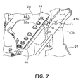
- a shim 43 can be mounted in two locations in the crosswise direction between the bottom surface of the base plate 28 and the top surface of the rear supporting portion 40 of the rear supporting frame 27 (only one is illustrated in FIG. 7 ).
- the shim 43 is used for adjusting the height of the exhaust gas post-processing device 18 and the pipe unit 23 when the base plate 28 upon which is mounted the exhaust gas post-processing device 18 is fixed to the rear supporting portion 40 of the rear supporting frame 27.
- the shim 43 is rectangular and has a pair of notches 43a that open to one side at both ends in the crosswise direction, and a through hole 43b located between the pair of notches 43a.
- the shim 43 is fixed to the top surface of the rear supporting portion 40 by a bolt 44.
- a large hole 28a with a diameter greater than the head of the bolt 44 is formed in the base plate 28 in the location where the bolt 44 is provided. Obstruction between the base plate 28 and the bolt 44 can be avoided as a result of the hole 28a. Therefore, the base plate 28 can be attached or detached with the shim 43 fixed to the rear supporting portion 40.
- the shim 43 can be prepared in various thicknesses or one or a plurality of shims 43 can be used in combination to allow the height to be adjusted.
- the exhaust gas post-processing device 18 is equipped with a diesel particulate filtering device 45, a connecting pipe 48, and a nitrogen oxide reduction catalyst device 47 in order from the exhaust gas upstream side of the engine 15 (hereinafter referred to simply as "upstream side").
- An urea aqueous solution mixing device 46 is attached to the connecting pipe 48.
- the diesel particulate filtering device 45 collects particulate matter such as soot and the like in the exhaust gas, and is mounted on the rear portion of the base plate 28 of the supporting mechanism 17.
- the urea aqueous solution mixing device 46 emits an urea aqueous solution sucked up by a pump that is not illustrated from an urea aqueous solution tank that is not illustrated, and adds the urea aqueous solution to the exhaust gas as a reducing agent.
- the added urea aqueous solution is hydrolyzed to become ammonia, and the ammonia is fed with the exhaust gas through the connecting pipe 48 to the nitrogen oxide reduction catalyst device 47.
- the ammonia from the urea aqueous solution mixing device 46 is used as the reducing agent to purify by reduction the nitrogen oxides in the exhaust gas in the nitrogen oxide reduction catalyst device 47.
- the nitrogen oxide reduction catalyst device 47 is mounted on the front portion of the base plate 28 of the supporting mechanism 17 in the same way as the diesel particulate filtering device 45.
- the diesel particulate filtering device 45 and the nitrogen oxide reduction catalyst device 47 are fixed to the base plate 28 via each of the separate attachment plates.
- the diesel particulate filtering device 45 and the nitrogen oxide reduction catalyst device 47 are disposed parallel to each other. Specifically, the diesel particulate filtering device 45 and the nitrogen oxide reduction catalyst device 47 are both cylindrical and the center axes thereof are disposed so as to extend in the crosswise direction and be parallel to each other.
- An exhaust gas inlet 45a is provided on the left edge portion of the diesel particulate filtering device 45, and an opening of the exhaust gas inlet 45a faces toward the rear.
- An exhaust gas outlet 45b is provided on the right edge portion of the diesel particulate filtering device 45, and an opening of the exhaust gas outlet 45b faces toward the front.
- An exhaust gas inlet 47a is provided on the left edge portion of the nitrogen oxide reduction catalyst device 47, and an opening of the exhaust gas inlet 47a faces toward the rear.
- An exhaust gas outlet 47b is provided on the right edge portion of the nitrogen oxide reduction catalyst device 47, and an opening of the exhaust gas outlet 47b faces toward the rear and obliquely upward.
- the connecting pipe 48 is disposed between the exhaust gas outlet 45b of the diesel particulate filtering device 45 and the exhaust gas inlet 47a of the nitrogen oxide reduction catalyst device 47.
- the connecting pipe 48 has a first bend section 48a, a linear section 48b, and a second bend section 48c, and the entire connecting pipe 48 forms an S shape.
- the first bend section 48a is located near the exhaust gas outlet 45b of the diesel particulate filtering device 45
- the second bend section 48c is located near the exhaust gas inlet 47a of the nitrogen oxide reduction catalyst device 47.
- the linear section 48b is located between the first bend section 48a and the second bend section 48c and is disposed parallel to the diesel particulate filtering device 45 and the nitrogen oxide reduction catalyst device 47.
- the urea aqueous solution mixing device 46 is provided on the first bend section 48a and emits an urea aqueous solution into the connecting pipe 48.
- the emitted urea aqueous solution becomes evenly mixed with the exhaust gas while passing through the long linear section 48b.
- the lengths in the crosswise direction of the diesel particulate filtering device 45 and the nitrogen oxide reduction catalyst device 47 are formed to be longer than the width in the crosswise direction of the base plate 28.
- FIG. 8 illustrates an enlargement of the pipe unit 23.
- the pipe unit 23 has an upstream side pipe 51 and a downstream side pipe 52.
- the upstream side pipe 51 includes a pipe body 54, and a front flange 55 and a rear flange 56 respectively provided at either end of the pipe body 54.
- Spherical joints 57 are provided between the pipe body 54 and the front and rear flanges 55, 56.
- the pipe body 54 is made of stainless steel and includes a linear extending section 54a that extends from the front toward the rear, and a bend section 54b that bends upward from the rear end portion of the extension 54a.
- Two bellows-like flexible pipe sections 54c, 54d are formed in the extending section 54a.
- the front and rear flanges 55, 56 respectively include rectangular connecting end faces 55a, 56a and pipe sections 55b, 56b that respectively extend from the connecting ends 55a, 56a.
- the connecting end face 55a of the front flange 55 is connected to an exhaust gas outlet of the turbo charger 22.
- the connecting end face 56a of the rear flange 56 is connected to the downstream side pipe 52.
- a spherical joint that uses the known technology disclosed in US Patent No. 2011/007415 may be used for example as the spherical joint 57.
- the upstream side pipe 51 is fixed to the left post 37 of the rear supporting frame 27 via a fixing plate 60 and a U-shaped metal fitting 61.
- the fixing plate 60 is L-shaped and a lower side thereof is fixed to the upper portion of the left post 37. Both ends of the U-shaped metal fitting 61 that holds the rear portion (exhaust gas downstream side) of the flexible pipe section 54d of the pipe body 54 are fixed to the standing side of the fixing plate 60 with nuts 62.
- the downstream side pipe 52 is a 90-degree elbow and includes a first pipe section 64 that is connected to the diesel particulate filtering device 45, and a second pipe section 65 that is orthogonal to the first pipe section 64.
- the second pipe section 65 is configured by the bend section 54b of the upstream side pipe 51 and a linking section that links the lower and upper sections of the connecting pipe 23.
- a flange 64a is formed at the exhaust gas downstream side end of the first pipe section 64 and is connected to the exhaust gas inlet 45a of the diesel particulate filtering device 45.
- a flange 65a is formed at the exhaust gas upstream side end of the second pipe section 65 and is connected to the connecting end face 56a of the rear flange 56 of the upstream side pipe 51.
- one or two bolt through holes H in the flange F is formed to have a larger diameter than the diameter of a coupling bolt B.
- the air cleaner 13 and a disposition thereof are explained with reference to FIGS. 2 and 11 .
- the air cleaner 13 is provided outside of the engine room and on the upper portion of the rear wheel fender 5a.
- the rear wheel fender 5a is configured of a fender front portion 5b and a fender rear portion 5c fastened to the fender front portion 5b.
- the fender front portion 5b is configured by a horizontal portion and a sloped portion that slopes forward and downward from the horizontal portion.
- the fender rear portion 5c is formed in an arced shape as seen from the side and covers the upper portion and the upper rear portion of the rear wheel 5.
- the air cleaner 13 is mounted on the horizontal portion of the fender front portion 5b.
- FIG. 11 is a plan view of the air cleaner 13 and portions related to the air cleaner 13 with the vehicle body cover 9 and the air cleaner cover 70 removed.
- the air cleaner 13 is cylindrical and a cap 71 that covers an air intake mouth 13a is provided on the upper portion of the air cleaner 13, and an openable and closable lid 13b is provided on the front portion of the air cleaner 13.
- a filter 72 is provided in an attachable and detachable manner inside the air cleaner 13.
- the air cleaner cover 70 covers most of the air cleaner 13 excluding the front end portion to which the air intake mouth 13a, the cap 71, and the lid 13b are attached.
- the filter 72 can be maintained and exchanged by opening the lid 13b and pulling the filter 72 out obliquely toward the front.
- the air cleaner 13 is disposed on the upper portion of the fender front portion 5b of the rear wheel fender 5a and the lateral side of the rear of the cab 6. More specifically, the front portion of the air cleaner 13 is located to the rear of the steps 10 and beside the rear end portion of the cab 6, and the rear portion of the air cleaner 13 is located beside the front portion of the operating fluid tank 19.
- a center axis C of the air cleaner 13 is substantially horizontal and is slanted with respect to a center axis extending to the front and rear of the vehicle so that the front portion of the air cleaner 13 is further away from the cab 6 than the rear portion.
- the filter 72 can be pulled out toward the front along the center axis C.
- the stopper 12 is provided on the cab 6 to limit the maximum opening degree of the door 11, and as illustrated in FIG. 12 , the front end portion of the air cleaner 13 is disposed in a location that does not obstruct the door 11 even if the door 11 is opened to the maximum to abut the stopper 12.
- the operator can stand on the steps 10 and open the lid 13b of the air cleaner 13 to easily perform maintenance or exchange the filter 72 as illustrated in FIG. 12 .
- air is introduced from the air cleaner 13 and fed into the engine 15 through the intake pipe 24 and the turbo charger 22.
- Exhaust gas from the engine 15 is introduced through the pipe unit 23 into the exhaust gas post-processing device 18 after driving the turbo charger 22.
- Particulate matter such as soot is collected by the diesel particulate filtering device 45 in the exhaust gas post-processing device 18.
- the particulate matter is introduced into the urea aqueous solution mixing device 46.
- An urea aqueous solution is emitted into the exhaust gas to mix with the exhaust gas in the urea aqueous solution mixing device 46. Consequently, the urea aqueous solution is hydrolyzed by the heat of the exhaust gas and water vapor in the exhaust gas to become ammonia.
- the ammonia generated in this way is fed with the exhaust gas through the connecting pipe 48 to the nitrogen oxide reduction catalyst device 47.
- the ammonia is used as the reducing agent to purify by reduction the nitrogen oxides in the exhaust gas in the nitrogen oxide reduction catalyst device 47.
- the diesel particulate filtering device 45 is desirably removed from the vehicle at certain time periods for maintenance. Accordingly, the exhaust gas post-processing device 18 is made into a sub-unit with the base plate 28 to facilitate assembly and maintenance of the exhaust gas post-processing device 18. When assembling the sub-unit onto the supporting mechanism 17, the pipe unit 23 is fixed to the engine 15 and the supporting mechanism 17.
- the front flange 55 of the upstream side pipe 51 is connected to the exhaust gas outlet of the turbo charger 22, and the downstream side of the flexible pipe 54d of the pipe body 54 is fixed to the supporting mechanism 17 with the fixing plate 60 and the U-shaped metal fitting 61.
- the upstream side pipe 51 and the spherical joint 57 on the exhaust gas upstream side are connected temporarily.
- the U-shaped metal fitting 61 is also fastened temporarily.
- the downstream side pipe 52 is connected to the upstream side pipe 51.
- the upstream side pipe 51 and the downstream side pipe 52 may be connected to each other before coupling the upstream side pipe 51 to the turbo charger 22.
- the flanges 56 and 65a are connected to each other with the exhaust gas downstream side spherical joint 57 in a temporarily fastened state.
- the sub-unit is supported by the supporting mechanism 17 in a state in which the pipe unit 23 is fixed to the engine 15 and the supporting mechanism 17 side.
- both the heights thereof are adjusted by the shim 43 and adjustment in the front-rear, vertical, and crosswise directions are performed by adjusting the assembly of the flanges 64a, 65a at both ends of the downstream side pipe 52.
- angle adjustment of the sub-unit and the supporting mechanism 17 is performed with the spherical joints 57 at either end of the upstream side pipe 51.
- the shim adjustments are rarely performed during maintenance since the adjustments are performed by the manufacturer before shipping.
- the engine 15 and the transmission 20 are mounted on the vehicle body frame 2 via the rubber mounts 21, and the exhaust gas post-processing device 18 is mounted directly onto the vehicle body frame 2 via the supporting mechanism 17.
- the exhaust gas post-processing device 18 is mounted directly onto the vehicle body frame 2 via the supporting mechanism 17.
- the difference between the two vibrations can be sufficiently absorbed since the relatively long flexible pipe sections 54c, 54d are formed in the extending section 54a of the pipe unit 23. Therefore, the vibration of the engine 15 can be suppressed.
- Exchanging and cleaning of the filter 72 are desirably performed at certain time periods in the air cleaner 13. At this time the filter 72 is desirably removed from the air cleaner 13.
- the operator When removing the filter 72 from the air cleaner 13, the operator stands on the steps 10 and opens the lid 13b of the air cleaner 13 as illustrated in FIG. 13.
- the filter 72 of the air cleaner 13 may be pulled out toward the front along the center axis C of the air cleaner 13. At this time, since the air cleaner 13 is slanted so that the front side thereof is further away from the cab 6 than the rear side thereof, the work to remove the filter 72 is easy to perform.
- a reduction in visibility to the rear is prevented and maintenance work on the air cleaner can be performed more easily in the wheel loader of the present invention since the air cleaner is disposed toward the rear portion of the cab and is disposed in a slanted manner so that the front from where the filter is pulled out is further away from the cab.
Description
- The present invention relates to a wheel loader and in particular to a wheel loader equipped with an air cleaner.
- An exhaust gas post-processing device is mounted on a wheel loader. The exhaust gas post-processing device includes a diesel particulate filtering device that collects and removes particulate matter of soot and the like included in the diesel engine exhaust gas. The diesel particulate filtering device is mounted in a row with an air cleaner on an upper portion of the engine. A nitrogen oxide reduction catalyst device may also be provided to remove NOx from the exhaust gas. The nitrogen oxide reduction catalyst device is provided on the exhaust downstream side of the diesel particulate filtering device.
- As described above, while the diesel particulate filtering device is disposed with the air cleaner on an upper portion of the engine, the installation location of the nitrogen oxide reduction catalyst device becomes a problem if the nitrogen oxide reduction catalyst device is installed in addition to the diesel particulate filtering device. Since the nitrogen oxide reduction catalyst device needs to be disposed on the exhaust downstream side of the diesel particulate filtering device, generally the nitrogen oxide reduction catalyst device is mounted in a row with the air cleaner and the diesel particulate filtering device on the upper portion of the engine when the nitrogen oxide reduction catalyst device is installed in addition to the diesel particulate filtering device.
- However, a problem arises with the spatial relationship when the air cleaner, the diesel particulate filtering device, and the nitrogen oxide reduction catalyst device are all disposed in a row above the engine. Therefore, while disposing a relatively light air cleaner above the diesel particulate filtering device and the nitrogen oxide reduction catalyst device may be considered, the top plate of the engine room becomes higher in this case and visibility to the rear is reduced.
- Accordingly, a configuration has been proposed for a large-scale dump truck described in
JP 2003-335268 A -
JP 2012-184602 A -
US 2012/018732 A1 discloses a motor grader having a cab placed on a mainframe, and two ground engaging members rotatably coupled to the mainframe. An engine is coupled to the mainframe and placed within an engine compartment. A cooling package includes a radiator coupled to the mainframe and placed within the engine compartment, where the radiator is placed forward the engine and rearward the cab. An enclosure partially encloses the engine compartment, and includes an air intake forward the radiator and rearward the cab and in line between the radiator and the cab. The enclosure includes the air intake forward the radiator and rearward the cab and in line between the radiator and the cab, thus enabling efficient operation of the cooling package. The radiator of the cooling package is placed forward the engine and rearward the cab, thus enabling efficient packaging of remaining components within the enclosure, and hence enhancing visibility of the surrounding terrain around the machine. - However, since the engine room is disposed to the rear of the cab in a wheel loader, visibility to the rear may become reduced if the configuration described in Patent Document 1 is applied as-is to the wheel loader. Further, the air cleaner needs to be disposed to allow for ease of maintenance work since the filter inside the air cleaner requires regular cleaning and exchanging at certain time periods.
- An object of the present invention is to dispose the air cleaner on the wheel loader in such a way as to prevent a reduction in visibility to the rear and to enable ease of maintenance work.
- A wheel loader according to a first aspect of the present invention has a cab with a driver's seat provided therein, steps provided beside the cab for ascending to and descending from the cab, an engine disposed to the rear of the cab, and an air cleaner. The air cleaner includes a filter that can be exchanged by being pulled out horizontally, and is connected to the engine via an intake pipe. The air cleaner is slanted so that a front side from which the filter can be pulled out is further away from the cab than an opposite rear side. The wheel loader is characterized in that the air cleaner is disposed to the outside of the vehicle cover, beside the rear of the cab, and to the rear of the steps, such that the filter can be pulled out toward the steps.
- The air cleaner in the wheel loader is provided on the outside of the vehicle body cover and to the rear of the cab, and is not provided on the engine room. The air cleaner is disposed so as to be slanted so that the front side from which the filter is pulled out is further away from the cab than the opposite rear side. The air cleaner is disposed beside the rear of the cab and to the rear of the steps in such a way, that the filter is pulled out toward the steps.
- In this case, since the air cleaner is disposed outside of the engine room, the top plate of the engine room does not need to be made higher even if the exhaust gas post-processing device is installed above the engine inside the engine room. Therefore, a reduction in visibility to the rear can be avoided even with the installation of the exhaust gas post-processing device. Further, an operator is able to perform maintenance of the air cleaner while standing on the steps and thus maintenance work becomes easier. Furthermore, since the air cleaner is disposed in a slanted manner so that the side from which the filter is pulled out is further away from the cab than the opposite side, the filter can be removed easily when exchanging the filter. Since the air cleaner is disposed to the rear of the steps, work can be performed more easily when the operator stands on the steps to perform the maintenance of the air cleaner.
- A wheel loader according to a second aspect of the present invention is related to the wheel loader of the first aspect, wherein the cab has a cab body and a door supported by a rear portion of the cab body so that the front side of the door is openable and closable. The air cleaner is disposed at a location that does not obstruct the door when the door is fully open.
- The door is not obstructed by the air cleaner when the operator opens or closes the door to enter or exit the cab.
- A wheel loader according to a third aspect of the present invention is related to the wheel loader of the first or second aspect, and further comprises an operating fluid tank disposed between the cab and the engine, wherein the air cleaner is disposed beside the operating fluid tank.
- Similar to the wheel loader of the first aspect, a reduction in visibility to the rear can be avoided even if the exhaust gas post-processing device is installed, and the maintenance work of the air cleaner can be performed more easily.
- A wheel loader according to a fourth aspect of the present invention is related to the wheel loader of any of the first to third aspects, and further comprises a rear wheel fender disposed above a rear wheel, wherein the air cleaner is fixed to an upper portion of the rear wheel fender.
- Similar to the wheel loader of the first and third aspects, a reduction in visibility to the rear can be avoided even if the exhaust gas post-processing device is installed, and the maintenance work of the air cleaner can be performed more easily.
- A wheel loader according to a fifth aspect of the present invention is related to the wheel loader of any of the first to fourth aspects, and further includes an exhaust gas post-processing device that is disposed above the engine and includes a diesel particulate filtering device and a nitrogen oxide reduction catalyst device that are disposed in a row in the front-back direction.
- Since the air cleaner is disposed toward the rear portion of the cab, the diesel particulate filtering device and the nitrogen oxide reduction catalyst device can be installed above the engine without hampering visibility to the rear.
- A wheel loader according to a sixth aspect of the present invention is related to the wheel loader of the fifth aspect, and further comprises a vehicle body frame that supports the engine, and a supporting mechanism that is fixed to the vehicle body frame and upon which is mounted the exhaust gas post-processing device.
- The exhaust gas post-processing device that includes the diesel particulate filtering device and the nitrogen oxide reduction catalyst device is heavy. As a result, when the above devices are supported directly by the engine, the center of mass of the structure including the engine increases and the engine vibration becomes very large.
- Accordingly, the supporting mechanism fixed to the vehicle body frame is provided in the wheel loader of the sixth aspect and the exhaust gas post-processing device is mounted on the supporting mechanism. As a result, engine vibration can be suppressed.
- A wheel loader according to an seventh aspect of the present invention further comprises an air cleaner cover covering portions except for a pull-out opening for the filter and an air intake mouth.
- The air cleaner can be protected by the air cleaner cover.
- A reduction in visibility to the rear is prevented and maintenance work on the air cleaner can be performed more easily in the wheel loader of the present invention as described above since the air cleaner is disposed toward the rear portion of the cab and is disposed in a slanted manner so that the front from where the filter is pulled out is further away from the cab.
-
-
FIG. 1 is an external perspective view of a wheel loader according to a first embodiment of the present invention. -
FIG. 2 is an external perspective partial view from the left front of the wheel loader ofFIG. 1 . -
FIG. 3 is a side partial view with the vehicle body cover of the wheel loader ofFIG. 1 removed. -
FIG. 4 illustrates a mounted state of an engine and a transmission. -
FIG. 5 is a perspective view illustrating an exhaust gas post-processing device and a supporting mechanism. -
FIG. 6 is an exploded perspective view of the supporting mechanism. -
FIG. 7 illustrates a shim attached to the supporting mechanism. -
FIG. 8 is an external perspective view of a pipe unit. -
FIG. 9 is a schematic view for explaining an adjustment function of a flange connecting portion. -
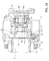
FIG. 10 is a plan view of a disposition of the air cleaner. -
FIG. 11 illustrates a relationship between the air cleaner and the door. -
FIG. 12 illustrates an appearance of maintenance work on the air cleaner. -
FIG. 1 illustrates an external perspective view of a wheel loader 1 according to an embodiment of the present invention.FIG. 2 illustrates a portion of the wheel loader on the left side of the cab. - In the following explanation, "front" refers to the front of the vehicle and "rear" refers to the rear of the vehicle. "Left" and "right" refer respectively to the left and right of the vehicle looking toward the front of the vehicle.
- The wheel loader 1 includes a
vehicle body frame 2, workingequipment 3, front wheels 4,rear wheels 5, and acab 6. The wheel loader 1 is capable of traveling due to the rotation of the front wheels 4 and therear wheels 5, and desired work can be conducted using the workingequipment 3. - The
vehicle body frame 2 includes a front body portion and a rear body portion which are connected to each other to allow for pivoting in the crosswise direction. The workingequipment 3 and the front wheels 4 are provided on the front body portion. Therear wheels 5 and thecab 6 are provided on the rear body portion. The workingequipment 3 is disposed at the front of the front body portion and includes a bucket 7, abucket cylinder 8 and the like.Fenders rear wheels 5. An operating cabin 6a and various operating members and an operating panel are provided inside thecab 6. - As illustrated in
FIG. 2 , steps 10 for ascending to and descending from thecab 6 are provided on the left side of thecab 6. Thesteps 10 are disposed in front of therear wheel fender 5a. Adoor 11 is provided in thecab 6 with the rear thereof supported by a hinge on thecab body 6b and the front thereof being openable and closable. The maximum degree of opening of thedoor 11 is limited by astopper 12 provided on the outside of thecab body 6b. Anair cleaner 13 is disposed on an upper portion of therear wheel fender 5a on the left side. A detailed explanation of theair cleaner 13 is provided below. Foreign matter in the air drawn into theengine 15 is removed and the air is purified by theair cleaner 13. -
FIG. 3 is a view of the rear body portion as seen from the left side of the vehicle with a vehicle body cover 9 (FIG. 1 ) to the rear of thecab 6 removed. As illustrated inFIG. 3 , theengine 15, a coolingunit 16 disposed to the rear of theengine 15, a supportingmechanism 17, and an exhaustgas post-processing device 18 mounted on the supportingmechanism 17 above theengine 15 are disposed in the rear portion of the rear body portion. An operatingfluid tank 19 is disposed between thecab 6 and theengine 15. - The
engine 15 is a so-called vertical mounted engine and is disposed so that a crankshaft extends in the front-back direction. Theengine 15 is fixed to atransmission 20 with bolts to form an integrated structure as illustrated inFIG. 4 . Theengine 15 and thetransmission 20 are supported in four locations on thevehicle body frame 2 via rubber mounts 21. - As illustrated in
FIG. 3 , aturbo charger 22 that supercharges intake air with the exhaust gas is provided on the left side of theengine 15. Theturbo charger 22 is provided so that an exhaust gas outlet faces to the rear. Apipe unit 23 is provided between theturbo charger 22 and the exhaustgas post-processing device 18. Aflexible intake pipe 24 made of rubber or plastic is provided between theturbo charger 22 and theair cleaner 13. A difference in vibration between theengine 15 and theair cleaner 13 is absorbed by theintake pipe 24. -
FIG. 5 is a perspective view of a portion ofFIG. 3 as seen from the rear.FIG. 6 is a perspective view illustrating the supportingmechanism 17 in a disassembled state. As illustrated inFIGS. 5 and6 , the supportingmechanism 17 is fixed directly to thevehicle body frame 2 with bolts and is configured by a front supportingframe 26, arear supporting frame 27, and abase plate 28. More specifically as illustrated inFIG. 5 ,side frames Brackets 29 are provided in the front and back of the left and right side frames 2a, 2b and the front supportingframe 26 and therear supporting frame 27 are fixed to thebrackets 29. - The front supporting
frame 26 includes left andright side portions top plate portion 32, and a connectingportion 33. Front portions of the left andright side portions portions 30a, 31 a. Plates of the left andright side portions attachment portions attachment portions bolts 34 to thebrackets 29 provided on the inside of the left and right side frames 2a, 2b. Thetop plate portion 32 is provided to connect the upper portions of the left andright side portions fluid tank 19 is mounted on the upper surface of thetop plate portion 32. That is, the front supportingframe 26 also acts as a base to support the operatingfluid tank 19. The connectingportion 33 connects the rear portions of the left andright side portions portion 33 projects further upward than the upper surface of thetop plate portion 32 to form afront supporting portion 35. The width in the crosswise direction of the front supportingportion 35 is formed to be narrower than the width in the crosswise direction of thetop plate portion 32. - The
rear supporting frame 27 includes left andright posts top beam 39, and arear supporting portion 40. The left andright posts attachment portions attachment portions bolts 41 to thebrackets 29 provided on the inside of the left and right side frames 2a, 2b. Thetop beam 39 connects the upper portions of the left andright posts rear supporting portion 40 is provided in the center portion in the crosswise direction of thetop beam 39. Therear supporting portion 40 projects further upward than thetop beam 39 and is formed to be at the same height as thefront supporting portion 35 of the front supportingframe 26. - Since the
rear supporting portion 40 projects upward further than thetop beam 39 and the width in the crosswise direction is shorter than thetop beam 39 in therear supporting frame 27 as described above, spaces S1, S2 for disposing members are formed in the crosswise direction of therear supporting portion 40. In the present embodiment, a portion of thepipe unit 23 and pipes 42a, 42b connected to acooling unit 16 are disposed so as to use the spaces S1, S2 as illustrated inFIG. 3 . - The
base plate 28 is provided between the front supportingportion 35 of the front supportingframe 26 and therear supporting portion 40 of the rear supportingframe 27. Thebase plate 28 is formed to have a rectangular shape and the width in the crosswise direction is substantially the same as the widths of the front supportingportion 35 and therear supporting portion 40. - As illustrated in
FIG. 7 , ashim 43 can be mounted in two locations in the crosswise direction between the bottom surface of thebase plate 28 and the top surface of therear supporting portion 40 of the rear supporting frame 27 (only one is illustrated inFIG. 7 ). Theshim 43 is used for adjusting the height of the exhaustgas post-processing device 18 and thepipe unit 23 when thebase plate 28 upon which is mounted the exhaustgas post-processing device 18 is fixed to therear supporting portion 40 of the rear supportingframe 27. Theshim 43 is rectangular and has a pair ofnotches 43a that open to one side at both ends in the crosswise direction, and a throughhole 43b located between the pair ofnotches 43a. - The
shim 43 is fixed to the top surface of therear supporting portion 40 by abolt 44. Alarge hole 28a with a diameter greater than the head of thebolt 44 is formed in thebase plate 28 in the location where thebolt 44 is provided. Obstruction between thebase plate 28 and thebolt 44 can be avoided as a result of thehole 28a. Therefore, thebase plate 28 can be attached or detached with theshim 43 fixed to therear supporting portion 40. - The
shim 43 can be prepared in various thicknesses or one or a plurality ofshims 43 can be used in combination to allow the height to be adjusted. - As illustrated in
FIGS. 5 and6 , the exhaustgas post-processing device 18 is equipped with a dieselparticulate filtering device 45, a connectingpipe 48, and a nitrogen oxidereduction catalyst device 47 in order from the exhaust gas upstream side of the engine 15 (hereinafter referred to simply as "upstream side"). An urea aqueoussolution mixing device 46 is attached to the connectingpipe 48. - The diesel
particulate filtering device 45 collects particulate matter such as soot and the like in the exhaust gas, and is mounted on the rear portion of thebase plate 28 of the supportingmechanism 17. The urea aqueoussolution mixing device 46 emits an urea aqueous solution sucked up by a pump that is not illustrated from an urea aqueous solution tank that is not illustrated, and adds the urea aqueous solution to the exhaust gas as a reducing agent. The added urea aqueous solution is hydrolyzed to become ammonia, and the ammonia is fed with the exhaust gas through the connectingpipe 48 to the nitrogen oxidereduction catalyst device 47. The ammonia from the urea aqueoussolution mixing device 46 is used as the reducing agent to purify by reduction the nitrogen oxides in the exhaust gas in the nitrogen oxidereduction catalyst device 47. The nitrogen oxidereduction catalyst device 47 is mounted on the front portion of thebase plate 28 of the supportingmechanism 17 in the same way as the dieselparticulate filtering device 45. The dieselparticulate filtering device 45 and the nitrogen oxidereduction catalyst device 47 are fixed to thebase plate 28 via each of the separate attachment plates. - The diesel
particulate filtering device 45 and the nitrogen oxidereduction catalyst device 47 are disposed parallel to each other. Specifically, the dieselparticulate filtering device 45 and the nitrogen oxidereduction catalyst device 47 are both cylindrical and the center axes thereof are disposed so as to extend in the crosswise direction and be parallel to each other. Anexhaust gas inlet 45a is provided on the left edge portion of the dieselparticulate filtering device 45, and an opening of theexhaust gas inlet 45a faces toward the rear. Anexhaust gas outlet 45b is provided on the right edge portion of the dieselparticulate filtering device 45, and an opening of theexhaust gas outlet 45b faces toward the front. Anexhaust gas inlet 47a is provided on the left edge portion of the nitrogen oxidereduction catalyst device 47, and an opening of theexhaust gas inlet 47a faces toward the rear. Anexhaust gas outlet 47b is provided on the right edge portion of the nitrogen oxidereduction catalyst device 47, and an opening of theexhaust gas outlet 47b faces toward the rear and obliquely upward. The connectingpipe 48 is disposed between theexhaust gas outlet 45b of the dieselparticulate filtering device 45 and theexhaust gas inlet 47a of the nitrogen oxidereduction catalyst device 47. - As illustrated in
FIGS. 5 and10 , the connectingpipe 48 has afirst bend section 48a, alinear section 48b, and asecond bend section 48c, and the entire connectingpipe 48 forms an S shape. Thefirst bend section 48a is located near theexhaust gas outlet 45b of the dieselparticulate filtering device 45, and thesecond bend section 48c is located near theexhaust gas inlet 47a of the nitrogen oxidereduction catalyst device 47. Thelinear section 48b is located between thefirst bend section 48a and thesecond bend section 48c and is disposed parallel to the dieselparticulate filtering device 45 and the nitrogen oxidereduction catalyst device 47. - The urea aqueous
solution mixing device 46 is provided on thefirst bend section 48a and emits an urea aqueous solution into the connectingpipe 48. The emitted urea aqueous solution becomes evenly mixed with the exhaust gas while passing through the longlinear section 48b. - The lengths in the crosswise direction of the diesel
particulate filtering device 45 and the nitrogen oxidereduction catalyst device 47 are formed to be longer than the width in the crosswise direction of thebase plate 28. -
FIG. 8 illustrates an enlargement of thepipe unit 23. Thepipe unit 23 has anupstream side pipe 51 and adownstream side pipe 52. - The
upstream side pipe 51 includes apipe body 54, and afront flange 55 and arear flange 56 respectively provided at either end of thepipe body 54.Spherical joints 57 are provided between thepipe body 54 and the front andrear flanges - The
pipe body 54 is made of stainless steel and includes a linear extendingsection 54a that extends from the front toward the rear, and abend section 54b that bends upward from the rear end portion of theextension 54a. Two bellows-likeflexible pipe sections section 54a. The front andrear flanges pipe sections end face 55a of thefront flange 55 is connected to an exhaust gas outlet of theturbo charger 22. The connectingend face 56a of therear flange 56 is connected to thedownstream side pipe 52. - A spherical joint that uses the known technology disclosed in
US Patent No. 2011/007415 may be used for example as the spherical joint 57. - As illustrated in
FIG. 8 , theupstream side pipe 51 is fixed to theleft post 37 of the rear supportingframe 27 via a fixingplate 60 and aU-shaped metal fitting 61. The fixingplate 60 is L-shaped and a lower side thereof is fixed to the upper portion of theleft post 37. Both ends of the U-shaped metal fitting 61 that holds the rear portion (exhaust gas downstream side) of theflexible pipe section 54d of thepipe body 54 are fixed to the standing side of the fixingplate 60 with nuts 62. - The
downstream side pipe 52 is a 90-degree elbow and includes afirst pipe section 64 that is connected to the dieselparticulate filtering device 45, and asecond pipe section 65 that is orthogonal to thefirst pipe section 64. Thesecond pipe section 65 is configured by thebend section 54b of theupstream side pipe 51 and a linking section that links the lower and upper sections of the connectingpipe 23. - A
flange 64a is formed at the exhaust gas downstream side end of thefirst pipe section 64 and is connected to theexhaust gas inlet 45a of the dieselparticulate filtering device 45. Aflange 65a is formed at the exhaust gas upstream side end of thesecond pipe section 65 and is connected to the connectingend face 56a of therear flange 56 of theupstream side pipe 51. - As schematically illustrated in
FIG. 9 , in the connection of a flange F (collective name for flanges), one or two bolt through holes H in the flange F is formed to have a larger diameter than the diameter of a coupling bolt B. As a result, when mounting the exhaustgas post-processing device 18 on thebase plate 28 to make a sub-unit and when assembling the sub-unit with thepipe unit 23 fixed to therear supporting frame 27, an assembly error can be absorbed even if an error exists in the positional relationship between the exhaustgas post-processing device 18 and thepipe unit 23. That is, the assembly structure of the flanges F functions as an adjusting mechanism for adjusting the assembly location. - The
air cleaner 13 and a disposition thereof are explained with reference toFIGS. 2 and11 . Theair cleaner 13 is provided outside of the engine room and on the upper portion of therear wheel fender 5a. Therear wheel fender 5a is configured of afender front portion 5b and a fenderrear portion 5c fastened to thefender front portion 5b. Thefender front portion 5b is configured by a horizontal portion and a sloped portion that slopes forward and downward from the horizontal portion. The fenderrear portion 5c is formed in an arced shape as seen from the side and covers the upper portion and the upper rear portion of therear wheel 5. Theair cleaner 13 is mounted on the horizontal portion of thefender front portion 5b. - As illustrated in
FIG. 2 , except for a portion thereof, theair cleaner 13 is covered by an aircleaner cover 70 that is provided on the outside of thevehicle body cover 9.FIG. 11 is a plan view of theair cleaner 13 and portions related to theair cleaner 13 with thevehicle body cover 9 and the aircleaner cover 70 removed. - As illustrated in
FIGS. 2 and11 , theair cleaner 13 is cylindrical and acap 71 that covers anair intake mouth 13a is provided on the upper portion of theair cleaner 13, and an openable andclosable lid 13b is provided on the front portion of theair cleaner 13. Afilter 72 is provided in an attachable and detachable manner inside theair cleaner 13. The aircleaner cover 70 covers most of theair cleaner 13 excluding the front end portion to which theair intake mouth 13a, thecap 71, and thelid 13b are attached. Thefilter 72 can be maintained and exchanged by opening thelid 13b and pulling thefilter 72 out obliquely toward the front. - The disposition of the
air cleaner 13 is explained in detail below. - As illustrated in
FIG. 11 , theair cleaner 13 is disposed on the upper portion of thefender front portion 5b of therear wheel fender 5a and the lateral side of the rear of thecab 6. More specifically, the front portion of theair cleaner 13 is located to the rear of thesteps 10 and beside the rear end portion of thecab 6, and the rear portion of theair cleaner 13 is located beside the front portion of the operatingfluid tank 19. A center axis C of theair cleaner 13 is substantially horizontal and is slanted with respect to a center axis extending to the front and rear of the vehicle so that the front portion of theair cleaner 13 is further away from thecab 6 than the rear portion. As described above, thefilter 72 can be pulled out toward the front along the center axis C. - As described above, the
stopper 12 is provided on thecab 6 to limit the maximum opening degree of thedoor 11, and as illustrated inFIG. 12 , the front end portion of theair cleaner 13 is disposed in a location that does not obstruct thedoor 11 even if thedoor 11 is opened to the maximum to abut thestopper 12. - Due to the disposition of the
air cleaner 13 as described above, the operator can stand on thesteps 10 and open thelid 13b of theair cleaner 13 to easily perform maintenance or exchange thefilter 72 as illustrated inFIG. 12 . - As illustrated in
FIG. 3 , air is introduced from theair cleaner 13 and fed into theengine 15 through theintake pipe 24 and theturbo charger 22. Exhaust gas from theengine 15 is introduced through thepipe unit 23 into the exhaustgas post-processing device 18 after driving theturbo charger 22. - Particulate matter such as soot is collected by the diesel
particulate filtering device 45 in the exhaustgas post-processing device 18. Next, the particulate matter is introduced into the urea aqueoussolution mixing device 46. An urea aqueous solution is emitted into the exhaust gas to mix with the exhaust gas in the urea aqueoussolution mixing device 46. Consequently, the urea aqueous solution is hydrolyzed by the heat of the exhaust gas and water vapor in the exhaust gas to become ammonia. The ammonia generated in this way is fed with the exhaust gas through the connectingpipe 48 to the nitrogen oxidereduction catalyst device 47. The ammonia is used as the reducing agent to purify by reduction the nitrogen oxides in the exhaust gas in the nitrogen oxidereduction catalyst device 47. - The diesel
particulate filtering device 45 is desirably removed from the vehicle at certain time periods for maintenance. Accordingly, the exhaustgas post-processing device 18 is made into a sub-unit with thebase plate 28 to facilitate assembly and maintenance of the exhaustgas post-processing device 18. When assembling the sub-unit onto the supportingmechanism 17, thepipe unit 23 is fixed to theengine 15 and the supportingmechanism 17. - Specifically, the
front flange 55 of theupstream side pipe 51 is connected to the exhaust gas outlet of theturbo charger 22, and the downstream side of theflexible pipe 54d of thepipe body 54 is fixed to the supportingmechanism 17 with the fixingplate 60 and theU-shaped metal fitting 61. When coupling theupstream side pipe 51 to theturbo charger 22, theupstream side pipe 51 and the spherical joint 57 on the exhaust gas upstream side are connected temporarily. The U-shaped metal fitting 61 is also fastened temporarily. - Next, the
downstream side pipe 52 is connected to theupstream side pipe 51. Theupstream side pipe 51 and thedownstream side pipe 52 may be connected to each other before coupling theupstream side pipe 51 to theturbo charger 22. As described above, in this case theflanges - As described above, the sub-unit is supported by the supporting
mechanism 17 in a state in which thepipe unit 23 is fixed to theengine 15 and the supportingmechanism 17 side. When assembling the sub-unit on the supportingmechanism 17, both the heights thereof are adjusted by theshim 43 and adjustment in the front-rear, vertical, and crosswise directions are performed by adjusting the assembly of theflanges downstream side pipe 52. Further, angle adjustment of the sub-unit and the supportingmechanism 17 is performed with thespherical joints 57 at either end of theupstream side pipe 51. The shim adjustments are rarely performed during maintenance since the adjustments are performed by the manufacturer before shipping. - Since the relatively long
flexible pipe sections upstream side pipe 51 of thepipe unit 23, an assembly error can be absorbed by theflexible pipe sections - As described above, when the locations of the sub-unit is adjusted appropriately with the
engine 15 and the supportingmechanism 17, the temporarily fastened portions are firmly fixed and the assembly work is completed. - In the state in which the exhaust
gas post-processing device 18 is assembled, theengine 15 and thetransmission 20 are mounted on thevehicle body frame 2 via the rubber mounts 21, and the exhaustgas post-processing device 18 is mounted directly onto thevehicle body frame 2 via the supportingmechanism 17. As a result, a difference arises between vibrations from theengine 15 and vibrations from the exhaustgas post-processing device 18 while the vehicle is operating. - However, the difference between the two vibrations can be sufficiently absorbed since the relatively long
flexible pipe sections section 54a of thepipe unit 23. Therefore, the vibration of theengine 15 can be suppressed. - Exchanging and cleaning of the
filter 72 are desirably performed at certain time periods in theair cleaner 13. At this time thefilter 72 is desirably removed from theair cleaner 13. - When removing the
filter 72 from theair cleaner 13, the operator stands on thesteps 10 and opens thelid 13b of theair cleaner 13 as illustrated in FIG. 13. Thefilter 72 of theair cleaner 13 may be pulled out toward the front along the center axis C of theair cleaner 13. At this time, since theair cleaner 13 is slanted so that the front side thereof is further away from thecab 6 than the rear side thereof, the work to remove thefilter 72 is easy to perform. -
- (1) Since the
air cleaner 13 is disposed outside of the engine room and beside the rear of thecab 6, the upper plate of the engine room does not become higher and the dieselparticulate filtering device 45 and the nitrogen oxidereduction catalyst device 47 can be disposed above theengine 15. Therefore, a reduction in visibility to the rear can be avoided even if the nitrogen oxidereduction catalyst device 47 is added to the exhaustgas post-processing device 18. - (2) The
air cleaner 13 is disposed to the rear of thesteps 10 and slanted so that the front side of theair cleaner 13 from which thefilter 72 is pulled out is further away from thecab 6 than the rear side. Therefore, the operator can easily pull out thefilter 72 while standing on thesteps 10 and maintenance work can be conducted more easily. - (3) The
air cleaner 13 is disposed at a location that does not obstruct thedoor 11 of thecab 6 when thedoor 11 is fully open. Therefore, the driver is able to enter and exit the operating cabin of thecab 6 without worrying about the opening or closing degree of thedoor 11. - (4) The exhaust
gas post-processing device 18 is mounted on the supportingmechanism 17 that is provided independently of theengine 15. Therefore, engine vibration can be suppressed more in comparison to when the diesel particulate filtering device is mounted on the engine as with the conventional device. - The present invention is not limited to the above embodiments and various changes and modifications may be made without departing from the spirit of the invention.
-
- (a) While the
air cleaner 13 is fixed to therear wheel fender 5a in the previous embodiment, the air cleaner may be fixed to another member so long as the air cleaner is located beside the rear of thecab 6. - (b) While a case in which the
rear wheel fender 5a is divided into two portions and theair cleaner 13 is fixed to thefender front portion 5b is described in the previous embodiment, theair cleaner 13 may be fixed to the upper portion of an integrated rear wheel fender. - (c) While a case in which the
steps 10 and theair cleaner 13 are provided on the left side of thecab 6 is described in the previous embodiment, thesteps 10 and theair cleaner 13 may be provided on the right side of thecab 6. - A reduction in visibility to the rear is prevented and maintenance work on the air cleaner can be performed more easily in the wheel loader of the present invention since the air cleaner is disposed toward the rear portion of the cab and is disposed in a slanted manner so that the front from where the filter is pulled out is further away from the cab.
-
- 1: Wheel loader
- 2: Vehicle body frame
- 6: Cab
- 5: Rear wheel
- 5a: Rear wheel fender
- 6a: Operating cabin
- 6b: Cab body
- 10: Steps
- 11: Door
- 12: Stopper
- 13: Air cleaner
- 13a: Air intake
- 13b: Lid
- 15: Engine
- 17: Supporting mechanism
- 18: Exhaust gas post-processing device
- 19: Operating fluid tank
- 45: Diesel particulate collection and filtering device
- 47: Selective reduction catalytic converter
Claims (7)
- A wheel loader (1) comprising:a cab (6) with a driver's seat provided therein;steps (10) provided beside the cab (6) for ascending to and descending from the cab (6);an engine (15) disposed to the rear of the cab (6);a vehicle body cover (9) that covers the engine (15); andan air cleaner (13) having therein a filter (72) that can be exchanged by being pulled out horizontally, the air cleaner (13) connected to the engine (15) via an intake pipe (24), the air cleaner (13) disposed in a slanted manner so that a front side of the air cleaner (13) from which the filter (45) can be pulled out is further away from the cab (6) than an opposite rear side;characterized in thatthe air cleaner (13) is disposed to the outside of the vehicle body cover (9), beside the rear of the cab (6), and to the rear of the steps (10), such that the filter (72) can be pulled out toward the steps (10).
- The wheel loader (1) according to claim 1, characterized in that
the cab (6) has a cab body (6b) and a door (11) supported by a rear portion of the cab body (6b) so that the front side of the door (11) is openable and closable; and
the air cleaner (13) is disposed at a location that does not obstruct the door (11) when the door (11) is fully open - The wheel loader (1) according to any of claims 1 to 2, characterized by
an operating fluid tank (19) disposed between the cab (6) and the engine (15); wherein
the air cleaner (13) is disposed beside the operating fluid tank (19). - The wheel loader (1) according to any of claims 1 to 3, characterized by
a rear wheel fender (5a) disposed above the rear wheel (5), wherein
the air cleaner (13) is fixed to an upper portion of the rear wheel fender (5a). - The wheel loader (1) according to any one of claims 1 to 4, characterized by
an exhaust gas post-processing device (18) that is disposed above the engine (15) and includes a diesel particulate filtering device (45) and a nitrogen oxide reduction catalyst device (47) that are disposed in a row in the front-back direction. - The wheel loader (1) according to claim 5, characterized by
a vehicle body frame (2) that supports the engine (15); and
a supporting mechanism (17) that is fixed to the vehicle body frame (2) and upon which is mounted the exhaust gas post-processing device (18). - The wheel loader (1) according to any of claims 1 to 6, characterized by
an air cleaner cover (70) covering portions except for a pull-out opening for the filter (72) and an air intake (13a) mouth.
Applications Claiming Priority (2)
| Application Number | Priority Date | Filing Date | Title |
|---|---|---|---|
| JP2012237063 | 2012-10-26 | ||
| PCT/JP2012/082114 WO2014064852A1 (en) | 2012-10-26 | 2012-12-12 | Wheel loader |
Publications (3)
| Publication Number | Publication Date |
|---|---|
| EP2746464A1 EP2746464A1 (en) | 2014-06-25 |
| EP2746464A4 EP2746464A4 (en) | 2014-06-25 |
| EP2746464B1 true EP2746464B1 (en) | 2015-03-04 |
Family
ID=49639688
Family Applications (1)
| Application Number | Title | Priority Date | Filing Date |
|---|---|---|---|
| EP12867723.4A Active EP2746464B1 (en) | 2012-10-26 | 2012-12-12 | Wheel loader |
Country Status (4)
| Country | Link |
|---|---|
| US (1) | US9353502B2 (en) |
| EP (1) | EP2746464B1 (en) |
| CN (1) | CN103906878B (en) |
| WO (1) | WO2014064852A1 (en) |
Families Citing this family (13)
| Publication number | Priority date | Publication date | Assignee | Title |
|---|---|---|---|---|
| JP6178149B2 (en) * | 2013-07-24 | 2017-08-09 | ヤンマー株式会社 | Tractor |
| JP6297905B2 (en) * | 2014-04-22 | 2018-03-20 | 日立建機株式会社 | Construction machinery |
| JP5647753B1 (en) * | 2014-06-30 | 2015-01-07 | 株式会社小松製作所 | Work vehicle |
| US9487079B2 (en) * | 2014-08-11 | 2016-11-08 | Deere & Company | Air inlet and cleaner arrangement for work vehicle |
| EP2985166B1 (en) * | 2014-08-14 | 2017-08-02 | CNH Industrial Italia S.p.A. | Exhaust system for an off-road vehicle |
| WO2015118712A1 (en) * | 2014-09-04 | 2015-08-13 | 株式会社小松製作所 | Wheel loader |
| WO2015141530A1 (en) * | 2015-03-10 | 2015-09-24 | 株式会社小松製作所 | Industrial vehicle |
| CN105035175B (en) * | 2015-07-30 | 2018-12-07 | 广西柳工机械股份有限公司 | Applied to the liquid-adding device on LNG loading machine |
| US10467826B2 (en) * | 2016-03-16 | 2019-11-05 | Komatsu Ltd. | Dump truck |
| WO2016163300A1 (en) * | 2016-03-31 | 2016-10-13 | 株式会社小松製作所 | Dump truck |
| CN107558526B (en) * | 2017-10-31 | 2023-08-18 | 三一重机有限公司 | Position-adjustable steel pipe clamp bracket and hydraulic excavator |
| CN107905922A (en) * | 2017-11-30 | 2018-04-13 | 安徽铜冠机械股份有限公司 | Underground transportation vehicle front engine air inlet system and exhaust system |
| CN109184890B (en) * | 2018-08-31 | 2020-07-21 | 广西柳工机械股份有限公司 | Loader engine aftertreatment system |
Family Cites Families (23)
| Publication number | Priority date | Publication date | Assignee | Title |
|---|---|---|---|---|
| US3720279A (en) * | 1971-02-17 | 1973-03-13 | Euclid | Combustion air intake system for an off-the-road vehicle |
| US4917202A (en) * | 1988-12-19 | 1990-04-17 | Caterpillar Inc. | Air inlet deflector assembly for an air cleaner |
| JP2003011679A (en) * | 2001-06-27 | 2003-01-15 | Shin Caterpillar Mitsubishi Ltd | Cooling device for construction machine |
| JP4090019B2 (en) | 2002-05-17 | 2008-05-28 | 株式会社小松製作所 | Easy vehicle assembly |
| US6874589B1 (en) * | 2002-12-16 | 2005-04-05 | Crane Carrier Company | Deck mounted air cleaner assembly for vehicle |
| CN100482901C (en) * | 2004-03-29 | 2009-04-29 | 株式会社久保田 | Swiveling utility machine having swivel deck |
| CN101069002B (en) * | 2004-12-27 | 2010-10-13 | 神钢建设机械株式会社 | Cooling structure of construction machine |
| JP4270239B2 (en) * | 2006-08-11 | 2009-05-27 | コベルコ建機株式会社 | Construction machinery |
| US7717205B2 (en) * | 2006-11-28 | 2010-05-18 | Caterpillar Inc. | Engine hood assembly enclosure with exhaust aftertreatment device integrated therein, and machine using same |
| JP4501945B2 (en) * | 2007-02-23 | 2010-07-14 | コベルコ建機株式会社 | Construction structure of filter for cooler of construction machine |
| US7836967B2 (en) * | 2008-07-28 | 2010-11-23 | Caterpillar Inc | Cooling system packaging arrangement for a machine |
| JP4724241B2 (en) | 2009-07-09 | 2011-07-13 | 株式会社東芝 | Disk storage device and data detection method |
| JP5325081B2 (en) * | 2009-12-07 | 2013-10-23 | 株式会社クボタ | Work vehicle |
| JP5033226B2 (en) * | 2010-08-02 | 2012-09-26 | 株式会社小松製作所 | Work vehicle |
| JP5641984B2 (en) * | 2011-03-07 | 2014-12-17 | 日立建機株式会社 | Work machine |
| CN202055274U (en) * | 2011-05-08 | 2011-11-30 | 煤炭科学研究总院太原研究院 | Multifunctional scraper |
| JP5508351B2 (en) * | 2011-06-30 | 2014-05-28 | 日立建機株式会社 | Work machine |
| JP5510466B2 (en) * | 2012-01-10 | 2014-06-04 | コベルコ建機株式会社 | Construction machinery |
| WO2014064853A1 (en) * | 2012-10-26 | 2014-05-01 | 株式会社小松製作所 | Work vehicle |
| WO2014064956A1 (en) * | 2012-10-26 | 2014-05-01 | 株式会社小松製作所 | Wheel loader |
| CN104302844B (en) * | 2013-02-22 | 2016-01-20 | 株式会社小松制作所 | Wheel loader |
| JP5867485B2 (en) * | 2013-11-20 | 2016-02-24 | コベルコ建機株式会社 | Construction machinery |
| WO2015118712A1 (en) * | 2014-09-04 | 2015-08-13 | 株式会社小松製作所 | Wheel loader |
-
2012
- 2012-12-12 US US14/001,353 patent/US9353502B2/en active Active
- 2012-12-12 CN CN201280014914.2A patent/CN103906878B/en active Active
- 2012-12-12 EP EP12867723.4A patent/EP2746464B1/en active Active
- 2012-12-12 WO PCT/JP2012/082114 patent/WO2014064852A1/en active Application Filing
Also Published As
| Publication number | Publication date |
|---|---|
| EP2746464A1 (en) | 2014-06-25 |
| CN103906878A (en) | 2014-07-02 |
| US9353502B2 (en) | 2016-05-31 |
| WO2014064852A1 (en) | 2014-05-01 |
| US20150299981A1 (en) | 2015-10-22 |
| CN103906878B (en) | 2015-06-24 |
| EP2746464A4 (en) | 2014-06-25 |
Similar Documents
| Publication | Publication Date | Title |
|---|---|---|
| EP2746464B1 (en) | Wheel loader | |
| EP2743472B1 (en) | Work vehicle | |
| EP2762644B1 (en) | Wheel loader | |
| EP2728075B1 (en) | Working machine | |
| JP4705130B2 (en) | Construction machinery | |
| EP2857244B1 (en) | Support mechanism, exhaust gas treatment unit, and wheel loader | |
| EP2853429B1 (en) | Support mechanism, exhaust gas treatment unit, and wheel loader | |
| JP5363681B1 (en) | Work vehicle | |
| US9169619B2 (en) | Wheel loader | |
| US9657456B2 (en) | Wheel loader | |
| US20160138243A1 (en) | Construction machine | |
| JP5325357B1 (en) | Wheel loader | |
| JP6338821B2 (en) | Construction machinery | |
| JP2017141664A (en) | Shovel |
Legal Events
| Date | Code | Title | Description |
|---|---|---|---|
| PUAI | Public reference made under article 153(3) epc to a published international application that has entered the european phase |
Free format text: ORIGINAL CODE: 0009012 |
|
| 17P | Request for examination filed |
Effective date: 20130812 |
|
| A4 | Supplementary search report drawn up and despatched |
Effective date: 20140327 |
|
| AK | Designated contracting states |
Kind code of ref document: A1 Designated state(s): AL AT BE BG CH CY CZ DE DK EE ES FI FR GB GR HR HU IE IS IT LI LT LU LV MC MK MT NL NO PL PT RO RS SE SI SK SM TR |
|
| GRAP | Despatch of communication of intention to grant a patent |
Free format text: ORIGINAL CODE: EPIDOSNIGR1 |
|
| RIC1 | Information provided on ipc code assigned before grant |
Ipc: E02F 9/08 20060101ALI20141016BHEP Ipc: E02F 9/00 20060101AFI20141016BHEP |
|
| DAX | Request for extension of the european patent (deleted) | ||
| INTG | Intention to grant announced |
Effective date: 20141105 |
|
| GRAS | Grant fee paid |
Free format text: ORIGINAL CODE: EPIDOSNIGR3 |
|
| GRAA | (expected) grant |
Free format text: ORIGINAL CODE: 0009210 |
|
| AK | Designated contracting states |
Kind code of ref document: B1 Designated state(s): AL AT BE BG CH CY CZ DE DK EE ES FI FR GB GR HR HU IE IS IT LI LT LU LV MC MK MT NL NO PL PT RO RS SE SI SK SM TR |
|
| REG | Reference to a national code |
Ref country code: GB Ref legal event code: FG4D |
|
| REG | Reference to a national code |
Ref country code: CH Ref legal event code: EP |
|
| REG | Reference to a national code |
Ref country code: IE Ref legal event code: FG4D |
|
| REG | Reference to a national code |
Ref country code: SE Ref legal event code: TRGR |
|
| REG | Reference to a national code |
Ref country code: AT Ref legal event code: REF Ref document number: 714047 Country of ref document: AT Kind code of ref document: T Effective date: 20150415 |
|
| REG | Reference to a national code |
Ref country code: DE Ref legal event code: R096 Ref document number: 602012005742 Country of ref document: DE Effective date: 20150416 |
|
| REG | Reference to a national code |
Ref country code: AT Ref legal event code: MK05 Ref document number: 714047 Country of ref document: AT Kind code of ref document: T Effective date: 20150304 Ref country code: NL Ref legal event code: VDEP Effective date: 20150304 |
|
| PG25 | Lapsed in a contracting state [announced via postgrant information from national office to epo] |
Ref country code: FI Free format text: LAPSE BECAUSE OF FAILURE TO SUBMIT A TRANSLATION OF THE DESCRIPTION OR TO PAY THE FEE WITHIN THE PRESCRIBED TIME-LIMIT Effective date: 20150304 Ref country code: NO Free format text: LAPSE BECAUSE OF FAILURE TO SUBMIT A TRANSLATION OF THE DESCRIPTION OR TO PAY THE FEE WITHIN THE PRESCRIBED TIME-LIMIT Effective date: 20150604 Ref country code: LT Free format text: LAPSE BECAUSE OF FAILURE TO SUBMIT A TRANSLATION OF THE DESCRIPTION OR TO PAY THE FEE WITHIN THE PRESCRIBED TIME-LIMIT Effective date: 20150304 Ref country code: ES Free format text: LAPSE BECAUSE OF FAILURE TO SUBMIT A TRANSLATION OF THE DESCRIPTION OR TO PAY THE FEE WITHIN THE PRESCRIBED TIME-LIMIT Effective date: 20150304 Ref country code: HR Free format text: LAPSE BECAUSE OF FAILURE TO SUBMIT A TRANSLATION OF THE DESCRIPTION OR TO PAY THE FEE WITHIN THE PRESCRIBED TIME-LIMIT Effective date: 20150304 |
|
| REG | Reference to a national code |
Ref country code: LT Ref legal event code: MG4D |
|
| PG25 | Lapsed in a contracting state [announced via postgrant information from national office to epo] |
Ref country code: LV Free format text: LAPSE BECAUSE OF FAILURE TO SUBMIT A TRANSLATION OF THE DESCRIPTION OR TO PAY THE FEE WITHIN THE PRESCRIBED TIME-LIMIT Effective date: 20150304 Ref country code: RS Free format text: LAPSE BECAUSE OF FAILURE TO SUBMIT A TRANSLATION OF THE DESCRIPTION OR TO PAY THE FEE WITHIN THE PRESCRIBED TIME-LIMIT Effective date: 20150304 Ref country code: AT Free format text: LAPSE BECAUSE OF FAILURE TO SUBMIT A TRANSLATION OF THE DESCRIPTION OR TO PAY THE FEE WITHIN THE PRESCRIBED TIME-LIMIT Effective date: 20150304 Ref country code: GR Free format text: LAPSE BECAUSE OF FAILURE TO SUBMIT A TRANSLATION OF THE DESCRIPTION OR TO PAY THE FEE WITHIN THE PRESCRIBED TIME-LIMIT Effective date: 20150605 |
|
| PG25 | Lapsed in a contracting state [announced via postgrant information from national office to epo] |
Ref country code: NL Free format text: LAPSE BECAUSE OF FAILURE TO SUBMIT A TRANSLATION OF THE DESCRIPTION OR TO PAY THE FEE WITHIN THE PRESCRIBED TIME-LIMIT Effective date: 20150304 |
|
| PG25 | Lapsed in a contracting state [announced via postgrant information from national office to epo] |
Ref country code: RO Free format text: LAPSE BECAUSE OF FAILURE TO SUBMIT A TRANSLATION OF THE DESCRIPTION OR TO PAY THE FEE WITHIN THE PRESCRIBED TIME-LIMIT Effective date: 20150304 Ref country code: SK Free format text: LAPSE BECAUSE OF FAILURE TO SUBMIT A TRANSLATION OF THE DESCRIPTION OR TO PAY THE FEE WITHIN THE PRESCRIBED TIME-LIMIT Effective date: 20150304 Ref country code: PT Free format text: LAPSE BECAUSE OF FAILURE TO SUBMIT A TRANSLATION OF THE DESCRIPTION OR TO PAY THE FEE WITHIN THE PRESCRIBED TIME-LIMIT Effective date: 20150706 Ref country code: CZ Free format text: LAPSE BECAUSE OF FAILURE TO SUBMIT A TRANSLATION OF THE DESCRIPTION OR TO PAY THE FEE WITHIN THE PRESCRIBED TIME-LIMIT Effective date: 20150304 Ref country code: EE Free format text: LAPSE BECAUSE OF FAILURE TO SUBMIT A TRANSLATION OF THE DESCRIPTION OR TO PAY THE FEE WITHIN THE PRESCRIBED TIME-LIMIT Effective date: 20150304 |
|
| PG25 | Lapsed in a contracting state [announced via postgrant information from national office to epo] |
Ref country code: IS Free format text: LAPSE BECAUSE OF FAILURE TO SUBMIT A TRANSLATION OF THE DESCRIPTION OR TO PAY THE FEE WITHIN THE PRESCRIBED TIME-LIMIT Effective date: 20150704 Ref country code: PL Free format text: LAPSE BECAUSE OF FAILURE TO SUBMIT A TRANSLATION OF THE DESCRIPTION OR TO PAY THE FEE WITHIN THE PRESCRIBED TIME-LIMIT Effective date: 20150304 |
|
| REG | Reference to a national code |
Ref country code: DE Ref legal event code: R097 Ref document number: 602012005742 Country of ref document: DE |
|
| PG25 | Lapsed in a contracting state [announced via postgrant information from national office to epo] |
Ref country code: IT Free format text: LAPSE BECAUSE OF FAILURE TO SUBMIT A TRANSLATION OF THE DESCRIPTION OR TO PAY THE FEE WITHIN THE PRESCRIBED TIME-LIMIT Effective date: 20150304 |
|
| PLBE | No opposition filed within time limit |
Free format text: ORIGINAL CODE: 0009261 |
|
| STAA | Information on the status of an ep patent application or granted ep patent |
Free format text: STATUS: NO OPPOSITION FILED WITHIN TIME LIMIT |
|
| PG25 | Lapsed in a contracting state [announced via postgrant information from national office to epo] |
Ref country code: DK Free format text: LAPSE BECAUSE OF FAILURE TO SUBMIT A TRANSLATION OF THE DESCRIPTION OR TO PAY THE FEE WITHIN THE PRESCRIBED TIME-LIMIT Effective date: 20150304 |
|
| 26N | No opposition filed |
Effective date: 20151207 |
|
| PG25 | Lapsed in a contracting state [announced via postgrant information from national office to epo] |
Ref country code: SI Free format text: LAPSE BECAUSE OF FAILURE TO SUBMIT A TRANSLATION OF THE DESCRIPTION OR TO PAY THE FEE WITHIN THE PRESCRIBED TIME-LIMIT Effective date: 20150304 |
|
| PG25 | Lapsed in a contracting state [announced via postgrant information from national office to epo] |
Ref country code: BE Free format text: LAPSE BECAUSE OF NON-PAYMENT OF DUE FEES Effective date: 20151231 |
|
| PG25 | Lapsed in a contracting state [announced via postgrant information from national office to epo] |
Ref country code: MC Free format text: LAPSE BECAUSE OF FAILURE TO SUBMIT A TRANSLATION OF THE DESCRIPTION OR TO PAY THE FEE WITHIN THE PRESCRIBED TIME-LIMIT Effective date: 20150304 Ref country code: LU Free format text: LAPSE BECAUSE OF FAILURE TO SUBMIT A TRANSLATION OF THE DESCRIPTION OR TO PAY THE FEE WITHIN THE PRESCRIBED TIME-LIMIT Effective date: 20151212 |
|
| REG | Reference to a national code |
Ref country code: CH Ref legal event code: PL |
|
| PG25 | Lapsed in a contracting state [announced via postgrant information from national office to epo] |
Ref country code: BE Free format text: LAPSE BECAUSE OF FAILURE TO SUBMIT A TRANSLATION OF THE DESCRIPTION OR TO PAY THE FEE WITHIN THE PRESCRIBED TIME-LIMIT Effective date: 20150304 |
|
| REG | Reference to a national code |
Ref country code: IE Ref legal event code: MM4A |
|
| REG | Reference to a national code |
Ref country code: FR Ref legal event code: ST Effective date: 20160831 |
|
| PG25 | Lapsed in a contracting state [announced via postgrant information from national office to epo] |
Ref country code: IE Free format text: LAPSE BECAUSE OF NON-PAYMENT OF DUE FEES Effective date: 20151212 Ref country code: CH Free format text: LAPSE BECAUSE OF NON-PAYMENT OF DUE FEES Effective date: 20151231 Ref country code: LI Free format text: LAPSE BECAUSE OF NON-PAYMENT OF DUE FEES Effective date: 20151231 |
|
| PG25 | Lapsed in a contracting state [announced via postgrant information from national office to epo] |
Ref country code: FR Free format text: LAPSE BECAUSE OF NON-PAYMENT OF DUE FEES Effective date: 20151231 |
|
| PG25 | Lapsed in a contracting state [announced via postgrant information from national office to epo] |
Ref country code: HU Free format text: LAPSE BECAUSE OF FAILURE TO SUBMIT A TRANSLATION OF THE DESCRIPTION OR TO PAY THE FEE WITHIN THE PRESCRIBED TIME-LIMIT; INVALID AB INITIO Effective date: 20121212 Ref country code: BG Free format text: LAPSE BECAUSE OF FAILURE TO SUBMIT A TRANSLATION OF THE DESCRIPTION OR TO PAY THE FEE WITHIN THE PRESCRIBED TIME-LIMIT Effective date: 20150304 Ref country code: SM Free format text: LAPSE BECAUSE OF FAILURE TO SUBMIT A TRANSLATION OF THE DESCRIPTION OR TO PAY THE FEE WITHIN THE PRESCRIBED TIME-LIMIT Effective date: 20150304 |
|
| PG25 | Lapsed in a contracting state [announced via postgrant information from national office to epo] |
Ref country code: CY Free format text: LAPSE BECAUSE OF FAILURE TO SUBMIT A TRANSLATION OF THE DESCRIPTION OR TO PAY THE FEE WITHIN THE PRESCRIBED TIME-LIMIT Effective date: 20150304 |
|
| GBPC | Gb: european patent ceased through non-payment of renewal fee |
Effective date: 20161212 |
|
| PG25 | Lapsed in a contracting state [announced via postgrant information from national office to epo] |
Ref country code: MT Free format text: LAPSE BECAUSE OF FAILURE TO SUBMIT A TRANSLATION OF THE DESCRIPTION OR TO PAY THE FEE WITHIN THE PRESCRIBED TIME-LIMIT Effective date: 20150304 |
|
| PG25 | Lapsed in a contracting state [announced via postgrant information from national office to epo] |
Ref country code: GB Free format text: LAPSE BECAUSE OF NON-PAYMENT OF DUE FEES Effective date: 20161212 |
|
| PG25 | Lapsed in a contracting state [announced via postgrant information from national office to epo] |
Ref country code: MK Free format text: LAPSE BECAUSE OF FAILURE TO SUBMIT A TRANSLATION OF THE DESCRIPTION OR TO PAY THE FEE WITHIN THE PRESCRIBED TIME-LIMIT Effective date: 20150304 |
|
| PG25 | Lapsed in a contracting state [announced via postgrant information from national office to epo] |
Ref country code: AL Free format text: LAPSE BECAUSE OF FAILURE TO SUBMIT A TRANSLATION OF THE DESCRIPTION OR TO PAY THE FEE WITHIN THE PRESCRIBED TIME-LIMIT Effective date: 20150304 Ref country code: TR Free format text: LAPSE BECAUSE OF FAILURE TO SUBMIT A TRANSLATION OF THE DESCRIPTION OR TO PAY THE FEE WITHIN THE PRESCRIBED TIME-LIMIT Effective date: 20150304 |
|
| PGFP | Annual fee paid to national office [announced via postgrant information from national office to epo] |
Ref country code: SE Payment date: 20231110 Year of fee payment: 12 Ref country code: DE Payment date: 20231031 Year of fee payment: 12 |