EP2873646B1 - Particules à base de silicium poreux, leur procédé de préparation et substance active d'anode les comprenant - Google Patents
Particules à base de silicium poreux, leur procédé de préparation et substance active d'anode les comprenant Download PDFInfo
- Publication number
- EP2873646B1 EP2873646B1 EP14814680.6A EP14814680A EP2873646B1 EP 2873646 B1 EP2873646 B1 EP 2873646B1 EP 14814680 A EP14814680 A EP 14814680A EP 2873646 B1 EP2873646 B1 EP 2873646B1
- Authority
- EP
- European Patent Office
- Prior art keywords
- porous silicon
- particles
- particle
- pores
- range
- Prior art date
- Legal status (The legal status is an assumption and is not a legal conclusion. Google has not performed a legal analysis and makes no representation as to the accuracy of the status listed.)
- Active
Links
- 239000011856 silicon-based particle Substances 0.000 title claims description 174
- 229910021426 porous silicon Inorganic materials 0.000 title claims description 155
- 239000006183 anode active material Substances 0.000 title claims description 45
- 238000000034 method Methods 0.000 title claims description 39
- 239000011148 porous material Substances 0.000 claims description 141
- 238000005530 etching Methods 0.000 claims description 99
- 239000002245 particle Substances 0.000 claims description 92
- VYPSYNLAJGMNEJ-UHFFFAOYSA-N Silicium dioxide Chemical compound O=[Si]=O VYPSYNLAJGMNEJ-UHFFFAOYSA-N 0.000 claims description 52
- 229910052814 silicon oxide Inorganic materials 0.000 claims description 52
- 229910052751 metal Inorganic materials 0.000 claims description 47
- 239000002184 metal Substances 0.000 claims description 47
- QSHDDOUJBYECFT-UHFFFAOYSA-N mercury Chemical compound [Hg] QSHDDOUJBYECFT-UHFFFAOYSA-N 0.000 claims description 45
- 229910052753 mercury Inorganic materials 0.000 claims description 45
- 239000003054 catalyst Substances 0.000 claims description 43
- XUIMIQQOPSSXEZ-UHFFFAOYSA-N Silicon Chemical compound [Si] XUIMIQQOPSSXEZ-UHFFFAOYSA-N 0.000 claims description 32
- 229910052710 silicon Inorganic materials 0.000 claims description 32
- 239000010703 silicon Substances 0.000 claims description 32
- OKTJSMMVPCPJKN-UHFFFAOYSA-N Carbon Chemical compound [C] OKTJSMMVPCPJKN-UHFFFAOYSA-N 0.000 claims description 30
- 239000010410 layer Substances 0.000 claims description 26
- 239000010949 copper Substances 0.000 claims description 23
- WHXSMMKQMYFTQS-UHFFFAOYSA-N Lithium Chemical compound [Li] WHXSMMKQMYFTQS-UHFFFAOYSA-N 0.000 claims description 21
- 229910052744 lithium Inorganic materials 0.000 claims description 21
- 230000008859 change Effects 0.000 claims description 19
- 229910052802 copper Inorganic materials 0.000 claims description 19
- 239000007800 oxidant agent Substances 0.000 claims description 19
- 230000001590 oxidative effect Effects 0.000 claims description 19
- RYGMFSIKBFXOCR-UHFFFAOYSA-N Copper Chemical compound [Cu] RYGMFSIKBFXOCR-UHFFFAOYSA-N 0.000 claims description 17
- KRHYYFGTRYWZRS-UHFFFAOYSA-N Fluorane Chemical compound F KRHYYFGTRYWZRS-UHFFFAOYSA-N 0.000 claims description 15
- 229910052799 carbon Inorganic materials 0.000 claims description 15
- PXHVJJICTQNCMI-UHFFFAOYSA-N Nickel Chemical compound [Ni] PXHVJJICTQNCMI-UHFFFAOYSA-N 0.000 claims description 14
- 238000002459 porosimetry Methods 0.000 claims description 14
- 238000002156 mixing Methods 0.000 claims description 13
- OJMIONKXNSYLSR-UHFFFAOYSA-N phosphorous acid Chemical compound OP(O)O OJMIONKXNSYLSR-UHFFFAOYSA-N 0.000 claims description 11
- 239000003575 carbonaceous material Substances 0.000 claims description 10
- BASFCYQUMIYNBI-UHFFFAOYSA-N platinum Chemical compound [Pt] BASFCYQUMIYNBI-UHFFFAOYSA-N 0.000 claims description 10
- 238000003756 stirring Methods 0.000 claims description 10
- 239000007833 carbon precursor Substances 0.000 claims description 9
- 238000000576 coating method Methods 0.000 claims description 8
- 239000011248 coating agent Substances 0.000 claims description 7
- 230000007423 decrease Effects 0.000 claims description 7
- 239000000203 mixture Substances 0.000 claims description 7
- 229910052759 nickel Inorganic materials 0.000 claims description 7
- 239000011247 coating layer Substances 0.000 claims description 6
- 230000008021 deposition Effects 0.000 claims description 5
- 238000010438 heat treatment Methods 0.000 claims description 5
- 229910021383 artificial graphite Inorganic materials 0.000 claims description 4
- 239000000463 material Substances 0.000 claims description 4
- 239000002931 mesocarbon microbead Substances 0.000 claims description 4
- 229910021382 natural graphite Inorganic materials 0.000 claims description 4
- 229910052697 platinum Inorganic materials 0.000 claims description 4
- 229920000049 Carbon (fiber) Polymers 0.000 claims description 3
- 239000004215 Carbon black (E152) Substances 0.000 claims description 3
- 239000006229 carbon black Substances 0.000 claims description 3
- 239000004917 carbon fiber Substances 0.000 claims description 3
- 229930195733 hydrocarbon Natural products 0.000 claims description 3
- 150000002430 hydrocarbons Chemical class 0.000 claims description 3
- DDFHBQSCUXNBSA-UHFFFAOYSA-N 5-(5-carboxythiophen-2-yl)thiophene-2-carboxylic acid Chemical compound S1C(C(=O)O)=CC=C1C1=CC=C(C(O)=O)S1 DDFHBQSCUXNBSA-UHFFFAOYSA-N 0.000 claims description 2
- 229910003638 H2SiF6 Inorganic materials 0.000 claims description 2
- 229910019142 PO4 Inorganic materials 0.000 claims description 2
- LSNNMFCWUKXFEE-UHFFFAOYSA-N Sulfurous acid Chemical compound OS(O)=O LSNNMFCWUKXFEE-UHFFFAOYSA-N 0.000 claims description 2
- 239000002253 acid Substances 0.000 claims description 2
- LDDQLRUQCUTJBB-UHFFFAOYSA-N ammonium fluoride Chemical compound [NH4+].[F-] LDDQLRUQCUTJBB-UHFFFAOYSA-N 0.000 claims description 2
- NBIIXXVUZAFLBC-UHFFFAOYSA-K phosphate Chemical compound [O-]P([O-])([O-])=O NBIIXXVUZAFLBC-UHFFFAOYSA-K 0.000 claims description 2
- 239000010452 phosphate Substances 0.000 claims description 2
- ZEFWRWWINDLIIV-UHFFFAOYSA-N tetrafluorosilane;dihydrofluoride Chemical compound F.F.F[Si](F)(F)F ZEFWRWWINDLIIV-UHFFFAOYSA-N 0.000 claims description 2
- 230000000052 comparative effect Effects 0.000 description 29
- 239000000243 solution Substances 0.000 description 26
- 239000007864 aqueous solution Substances 0.000 description 15
- 239000003792 electrolyte Substances 0.000 description 15
- 238000009826 distribution Methods 0.000 description 14
- 239000002002 slurry Substances 0.000 description 14
- 229910000040 hydrogen fluoride Inorganic materials 0.000 description 12
- ARUVKPQLZAKDPS-UHFFFAOYSA-L copper(II) sulfate Chemical compound [Cu+2].[O-][S+2]([O-])([O-])[O-] ARUVKPQLZAKDPS-UHFFFAOYSA-L 0.000 description 9
- SQGYOTSLMSWVJD-UHFFFAOYSA-N silver(1+) nitrate Chemical compound [Ag+].[O-]N(=O)=O SQGYOTSLMSWVJD-UHFFFAOYSA-N 0.000 description 9
- 238000005259 measurement Methods 0.000 description 8
- -1 polyethylene Polymers 0.000 description 8
- 238000007086 side reaction Methods 0.000 description 8
- 239000008151 electrolyte solution Substances 0.000 description 7
- 229910002804 graphite Inorganic materials 0.000 description 7
- 239000010439 graphite Substances 0.000 description 7
- 239000000843 powder Substances 0.000 description 7
- 230000008569 process Effects 0.000 description 7
- WYURNTSHIVDZCO-UHFFFAOYSA-N Tetrahydrofuran Chemical compound C1CCOC1 WYURNTSHIVDZCO-UHFFFAOYSA-N 0.000 description 6
- 230000015572 biosynthetic process Effects 0.000 description 6
- 238000003486 chemical etching Methods 0.000 description 6
- 230000000694 effects Effects 0.000 description 6
- BVKZGUZCCUSVTD-UHFFFAOYSA-L Carbonate Chemical compound [O-]C([O-])=O BVKZGUZCCUSVTD-UHFFFAOYSA-L 0.000 description 5
- SECXISVLQFMRJM-UHFFFAOYSA-N N-Methylpyrrolidone Chemical compound CN1CCCC1=O SECXISVLQFMRJM-UHFFFAOYSA-N 0.000 description 5
- GRYLNZFGIOXLOG-UHFFFAOYSA-N Nitric acid Chemical compound O[N+]([O-])=O GRYLNZFGIOXLOG-UHFFFAOYSA-N 0.000 description 5
- QAOWNCQODCNURD-UHFFFAOYSA-N Sulfuric acid Chemical compound OS(O)(=O)=O QAOWNCQODCNURD-UHFFFAOYSA-N 0.000 description 5
- 239000011230 binding agent Substances 0.000 description 5
- 239000006258 conductive agent Substances 0.000 description 5
- 229910000365 copper sulfate Inorganic materials 0.000 description 5
- 230000001186 cumulative effect Effects 0.000 description 5
- 230000003247 decreasing effect Effects 0.000 description 5
- 229910017604 nitric acid Inorganic materials 0.000 description 5
- 229910052709 silver Inorganic materials 0.000 description 5
- 239000004332 silver Substances 0.000 description 5
- 239000002904 solvent Substances 0.000 description 5
- IJGRMHOSHXDMSA-UHFFFAOYSA-N Atomic nitrogen Chemical compound N#N IJGRMHOSHXDMSA-UHFFFAOYSA-N 0.000 description 4
- 238000004438 BET method Methods 0.000 description 4
- VGGSQFUCUMXWEO-UHFFFAOYSA-N Ethene Chemical compound C=C VGGSQFUCUMXWEO-UHFFFAOYSA-N 0.000 description 4
- 239000005977 Ethylene Substances 0.000 description 4
- VEXZGXHMUGYJMC-UHFFFAOYSA-N Hydrochloric acid Chemical compound Cl VEXZGXHMUGYJMC-UHFFFAOYSA-N 0.000 description 4
- XEEYBQQBJWHFJM-UHFFFAOYSA-N Iron Chemical compound [Fe] XEEYBQQBJWHFJM-UHFFFAOYSA-N 0.000 description 4
- 229910052782 aluminium Inorganic materials 0.000 description 4
- 238000004458 analytical method Methods 0.000 description 4
- 239000006182 cathode active material Substances 0.000 description 4
- 229920001577 copolymer Polymers 0.000 description 4
- 229910000366 copper(II) sulfate Inorganic materials 0.000 description 4
- 238000001739 density measurement Methods 0.000 description 4
- 238000000151 deposition Methods 0.000 description 4
- 239000002270 dispersing agent Substances 0.000 description 4
- 238000000454 electroless metal deposition Methods 0.000 description 4
- 229910003002 lithium salt Inorganic materials 0.000 description 4
- 159000000002 lithium salts Chemical class 0.000 description 4
- 239000003960 organic solvent Substances 0.000 description 4
- 229920000642 polymer Polymers 0.000 description 4
- 238000002360 preparation method Methods 0.000 description 4
- 238000001878 scanning electron micrograph Methods 0.000 description 4
- 239000000126 substance Substances 0.000 description 4
- QTBSBXVTEAMEQO-UHFFFAOYSA-N Acetic acid Chemical compound CC(O)=O QTBSBXVTEAMEQO-UHFFFAOYSA-N 0.000 description 3
- WEVYAHXRMPXWCK-UHFFFAOYSA-N Acetonitrile Chemical compound CC#N WEVYAHXRMPXWCK-UHFFFAOYSA-N 0.000 description 3
- OIFBSDVPJOWBCH-UHFFFAOYSA-N Diethyl carbonate Chemical compound CCOC(=O)OCC OIFBSDVPJOWBCH-UHFFFAOYSA-N 0.000 description 3
- XEKOWRVHYACXOJ-UHFFFAOYSA-N Ethyl acetate Chemical compound CCOC(C)=O XEKOWRVHYACXOJ-UHFFFAOYSA-N 0.000 description 3
- KMTRUDSVKNLOMY-UHFFFAOYSA-N Ethylene carbonate Chemical compound O=C1OCCO1 KMTRUDSVKNLOMY-UHFFFAOYSA-N 0.000 description 3
- 240000008042 Zea mays Species 0.000 description 3
- 235000005824 Zea mays ssp. parviglumis Nutrition 0.000 description 3
- 235000002017 Zea mays subsp mays Nutrition 0.000 description 3
- XAGFODPZIPBFFR-UHFFFAOYSA-N aluminium Chemical compound [Al] XAGFODPZIPBFFR-UHFFFAOYSA-N 0.000 description 3
- 239000011651 chromium Substances 0.000 description 3
- 235000005822 corn Nutrition 0.000 description 3
- 239000013078 crystal Substances 0.000 description 3
- 239000000835 fiber Substances 0.000 description 3
- XPFVYQJUAUNWIW-UHFFFAOYSA-N furfuryl alcohol Chemical compound OCC1=CC=CO1 XPFVYQJUAUNWIW-UHFFFAOYSA-N 0.000 description 3
- 229910052742 iron Inorganic materials 0.000 description 3
- 238000007561 laser diffraction method Methods 0.000 description 3
- 239000011777 magnesium Substances 0.000 description 3
- 239000011572 manganese Substances 0.000 description 3
- VLTRZXGMWDSKGL-UHFFFAOYSA-M perchlorate Inorganic materials [O-]Cl(=O)(=O)=O VLTRZXGMWDSKGL-UHFFFAOYSA-M 0.000 description 3
- 229910001961 silver nitrate Inorganic materials 0.000 description 3
- 238000004381 surface treatment Methods 0.000 description 3
- YLQBMQCUIZJEEH-UHFFFAOYSA-N tetrahydrofuran Natural products C=1C=COC=1 YLQBMQCUIZJEEH-UHFFFAOYSA-N 0.000 description 3
- DHKHKXVYLBGOIT-UHFFFAOYSA-N 1,1-Diethoxyethane Chemical compound CCOC(C)OCC DHKHKXVYLBGOIT-UHFFFAOYSA-N 0.000 description 2
- YEJRWHAVMIAJKC-UHFFFAOYSA-N 4-Butyrolactone Chemical compound O=C1CCCO1 YEJRWHAVMIAJKC-UHFFFAOYSA-N 0.000 description 2
- SBLRHMKNNHXPHG-UHFFFAOYSA-N 4-fluoro-1,3-dioxolan-2-one Chemical compound FC1COC(=O)O1 SBLRHMKNNHXPHG-UHFFFAOYSA-N 0.000 description 2
- CSCPPACGZOOCGX-UHFFFAOYSA-N Acetone Chemical compound CC(C)=O CSCPPACGZOOCGX-UHFFFAOYSA-N 0.000 description 2
- XKRFYHLGVUSROY-UHFFFAOYSA-N Argon Chemical compound [Ar] XKRFYHLGVUSROY-UHFFFAOYSA-N 0.000 description 2
- IAZDPXIOMUYVGZ-UHFFFAOYSA-N Dimethylsulphoxide Chemical compound CS(C)=O IAZDPXIOMUYVGZ-UHFFFAOYSA-N 0.000 description 2
- 229920002943 EPDM rubber Polymers 0.000 description 2
- YCKRFDGAMUMZLT-UHFFFAOYSA-N Fluorine atom Chemical compound [F] YCKRFDGAMUMZLT-UHFFFAOYSA-N 0.000 description 2
- NIPNSKYNPDTRPC-UHFFFAOYSA-N N-[2-oxo-2-(2,4,6,7-tetrahydrotriazolo[4,5-c]pyridin-5-yl)ethyl]-2-[[3-(trifluoromethoxy)phenyl]methylamino]pyrimidine-5-carboxamide Chemical compound O=C(CNC(=O)C=1C=NC(=NC=1)NCC1=CC(=CC=C1)OC(F)(F)F)N1CC2=C(CC1)NN=N2 NIPNSKYNPDTRPC-UHFFFAOYSA-N 0.000 description 2
- 229910002651 NO3 Inorganic materials 0.000 description 2
- 239000002033 PVDF binder Substances 0.000 description 2
- XLOMVQKBTHCTTD-UHFFFAOYSA-N Zinc monoxide Chemical compound [Zn]=O XLOMVQKBTHCTTD-UHFFFAOYSA-N 0.000 description 2
- 239000006230 acetylene black Substances 0.000 description 2
- 150000001450 anions Chemical class 0.000 description 2
- 229910052796 boron Inorganic materials 0.000 description 2
- 239000011575 calcium Substances 0.000 description 2
- 238000006243 chemical reaction Methods 0.000 description 2
- 229910001914 chlorine tetroxide Inorganic materials 0.000 description 2
- 229910052804 chromium Inorganic materials 0.000 description 2
- 150000001875 compounds Chemical class 0.000 description 2
- IEJIGPNLZYLLBP-UHFFFAOYSA-N dimethyl carbonate Chemical compound COC(=O)OC IEJIGPNLZYLLBP-UHFFFAOYSA-N 0.000 description 2
- 229910001873 dinitrogen Inorganic materials 0.000 description 2
- GNTDGMZSJNCJKK-UHFFFAOYSA-N divanadium pentaoxide Chemical compound O=[V](=O)O[V](=O)=O GNTDGMZSJNCJKK-UHFFFAOYSA-N 0.000 description 2
- FKRCODPIKNYEAC-UHFFFAOYSA-N ethyl propionate Chemical compound CCOC(=O)CC FKRCODPIKNYEAC-UHFFFAOYSA-N 0.000 description 2
- 239000011737 fluorine Substances 0.000 description 2
- 229910052731 fluorine Inorganic materials 0.000 description 2
- 229910052733 gallium Inorganic materials 0.000 description 2
- MLFHJEHSLIIPHL-UHFFFAOYSA-N isoamyl acetate Chemical compound CC(C)CCOC(C)=O MLFHJEHSLIIPHL-UHFFFAOYSA-N 0.000 description 2
- 239000007788 liquid Substances 0.000 description 2
- 229910000625 lithium cobalt oxide Inorganic materials 0.000 description 2
- BFZPBUKRYWOWDV-UHFFFAOYSA-N lithium;oxido(oxo)cobalt Chemical compound [Li+].[O-][Co]=O BFZPBUKRYWOWDV-UHFFFAOYSA-N 0.000 description 2
- 229910052749 magnesium Inorganic materials 0.000 description 2
- 229910052748 manganese Inorganic materials 0.000 description 2
- TZIHFWKZFHZASV-UHFFFAOYSA-N methyl formate Chemical compound COC=O TZIHFWKZFHZASV-UHFFFAOYSA-N 0.000 description 2
- 239000005543 nano-size silicon particle Substances 0.000 description 2
- 239000004745 nonwoven fabric Substances 0.000 description 2
- 230000003647 oxidation Effects 0.000 description 2
- 238000007254 oxidation reaction Methods 0.000 description 2
- 230000000704 physical effect Effects 0.000 description 2
- 229920006254 polymer film Polymers 0.000 description 2
- 229920000098 polyolefin Polymers 0.000 description 2
- 229920002981 polyvinylidene fluoride Polymers 0.000 description 2
- RUOJZAUFBMNUDX-UHFFFAOYSA-N propylene carbonate Chemical compound CC1COC(=O)O1 RUOJZAUFBMNUDX-UHFFFAOYSA-N 0.000 description 2
- 150000003839 salts Chemical class 0.000 description 2
- 239000011734 sodium Substances 0.000 description 2
- 239000010936 titanium Substances 0.000 description 2
- 238000005406 washing Methods 0.000 description 2
- 239000011701 zinc Substances 0.000 description 2
- VAYTZRYEBVHVLE-UHFFFAOYSA-N 1,3-dioxol-2-one Chemical compound O=C1OC=CO1 VAYTZRYEBVHVLE-UHFFFAOYSA-N 0.000 description 1
- HFZLSTDPRQSZCQ-UHFFFAOYSA-N 1-pyrrolidin-3-ylpyrrolidine Chemical compound C1CCCN1C1CNCC1 HFZLSTDPRQSZCQ-UHFFFAOYSA-N 0.000 description 1
- UHOPWFKONJYLCF-UHFFFAOYSA-N 2-(2-sulfanylethyl)isoindole-1,3-dione Chemical compound C1=CC=C2C(=O)N(CCS)C(=O)C2=C1 UHOPWFKONJYLCF-UHFFFAOYSA-N 0.000 description 1
- WWSJZGAPAVMETJ-UHFFFAOYSA-N 2-[4-[2-(2,3-dihydro-1H-inden-2-ylamino)pyrimidin-5-yl]-3-ethoxypyrazol-1-yl]-1-(2,4,6,7-tetrahydrotriazolo[4,5-c]pyridin-5-yl)ethanone Chemical compound C1C(CC2=CC=CC=C12)NC1=NC=C(C=N1)C=1C(=NN(C=1)CC(=O)N1CC2=C(CC1)NN=N2)OCC WWSJZGAPAVMETJ-UHFFFAOYSA-N 0.000 description 1
- ZYPDJSJJXZWZJJ-UHFFFAOYSA-N 2-[4-[2-(2,3-dihydro-1H-inden-2-ylamino)pyrimidin-5-yl]-3-piperidin-4-yloxypyrazol-1-yl]-1-(2,4,6,7-tetrahydrotriazolo[4,5-c]pyridin-5-yl)ethanone Chemical compound C1C(CC2=CC=CC=C12)NC1=NC=C(C=N1)C=1C(=NN(C=1)CC(=O)N1CC2=C(CC1)NN=N2)OC1CCNCC1 ZYPDJSJJXZWZJJ-UHFFFAOYSA-N 0.000 description 1
- WZFUQSJFWNHZHM-UHFFFAOYSA-N 2-[4-[2-(2,3-dihydro-1H-inden-2-ylamino)pyrimidin-5-yl]piperazin-1-yl]-1-(2,4,6,7-tetrahydrotriazolo[4,5-c]pyridin-5-yl)ethanone Chemical compound C1C(CC2=CC=CC=C12)NC1=NC=C(C=N1)N1CCN(CC1)CC(=O)N1CC2=C(CC1)NN=N2 WZFUQSJFWNHZHM-UHFFFAOYSA-N 0.000 description 1
- SJHAYVFVKRXMKG-UHFFFAOYSA-N 4-methyl-1,3,2-dioxathiolane 2-oxide Chemical compound CC1COS(=O)O1 SJHAYVFVKRXMKG-UHFFFAOYSA-N 0.000 description 1
- ZOXJGFHDIHLPTG-UHFFFAOYSA-N Boron Chemical compound [B] ZOXJGFHDIHLPTG-UHFFFAOYSA-N 0.000 description 1
- OYPRJOBELJOOCE-UHFFFAOYSA-N Calcium Chemical compound [Ca] OYPRJOBELJOOCE-UHFFFAOYSA-N 0.000 description 1
- 229920002134 Carboxymethyl cellulose Polymers 0.000 description 1
- VYZAMTAEIAYCRO-UHFFFAOYSA-N Chromium Chemical compound [Cr] VYZAMTAEIAYCRO-UHFFFAOYSA-N 0.000 description 1
- 229910018039 Cu2V2O7 Inorganic materials 0.000 description 1
- XTHFKEDIFFGKHM-UHFFFAOYSA-N Dimethoxyethane Chemical compound COCCOC XTHFKEDIFFGKHM-UHFFFAOYSA-N 0.000 description 1
- LFQSCWFLJHTTHZ-UHFFFAOYSA-N Ethanol Chemical compound CCO LFQSCWFLJHTTHZ-UHFFFAOYSA-N 0.000 description 1
- 229910005143 FSO2 Inorganic materials 0.000 description 1
- 229910017354 Fe2(MoO4)3 Inorganic materials 0.000 description 1
- GYHNNYVSQQEPJS-UHFFFAOYSA-N Gallium Chemical compound [Ga] GYHNNYVSQQEPJS-UHFFFAOYSA-N 0.000 description 1
- UFHFLCQGNIYNRP-UHFFFAOYSA-N Hydrogen Chemical compound [H][H] UFHFLCQGNIYNRP-UHFFFAOYSA-N 0.000 description 1
- 229920002153 Hydroxypropyl cellulose Polymers 0.000 description 1
- DGAQECJNVWCQMB-PUAWFVPOSA-M Ilexoside XXIX Chemical compound C[C@@H]1CC[C@@]2(CC[C@@]3(C(=CC[C@H]4[C@]3(CC[C@@H]5[C@@]4(CC[C@@H](C5(C)C)OS(=O)(=O)[O-])C)C)[C@@H]2[C@]1(C)O)C)C(=O)O[C@H]6[C@@H]([C@H]([C@@H]([C@H](O6)CO)O)O)O.[Na+] DGAQECJNVWCQMB-PUAWFVPOSA-M 0.000 description 1
- 229910007101 Li1+yMn2-yO4 Inorganic materials 0.000 description 1
- 229910007132 Li1+yMn2−yO4 Inorganic materials 0.000 description 1
- 229910003349 Li2CuO2 Inorganic materials 0.000 description 1
- 229910010228 Li2Mn3MO8 Inorganic materials 0.000 description 1
- 229910010521 LiFe3O4 Inorganic materials 0.000 description 1
- 229910014385 LiMn2-yMyO2 Inorganic materials 0.000 description 1
- 229910014774 LiMn2O3 Inorganic materials 0.000 description 1
- 229910014439 LiMn2−yMyO2 Inorganic materials 0.000 description 1
- 229910002993 LiMnO2 Inorganic materials 0.000 description 1
- 229910014713 LiMnO3 Inorganic materials 0.000 description 1
- 229910014383 LiNi1-yMyO2 Inorganic materials 0.000 description 1
- 229910014952 LiNi1−yMyO2 Inorganic materials 0.000 description 1
- 229910001290 LiPF6 Inorganic materials 0.000 description 1
- 229910012930 LiV3O3 Inorganic materials 0.000 description 1
- HBBGRARXTFLTSG-UHFFFAOYSA-N Lithium ion Chemical compound [Li+] HBBGRARXTFLTSG-UHFFFAOYSA-N 0.000 description 1
- 229910002097 Lithium manganese(III,IV) oxide Inorganic materials 0.000 description 1
- FYYHWMGAXLPEAU-UHFFFAOYSA-N Magnesium Chemical compound [Mg] FYYHWMGAXLPEAU-UHFFFAOYSA-N 0.000 description 1
- PWHULOQIROXLJO-UHFFFAOYSA-N Manganese Chemical compound [Mn] PWHULOQIROXLJO-UHFFFAOYSA-N 0.000 description 1
- RJUFJBKOKNCXHH-UHFFFAOYSA-N Methyl propionate Chemical compound CCC(=O)OC RJUFJBKOKNCXHH-UHFFFAOYSA-N 0.000 description 1
- 229910003684 NixCoyMnz Inorganic materials 0.000 description 1
- 229910004150 O2-cAc Inorganic materials 0.000 description 1
- ISWSIDIOOBJBQZ-UHFFFAOYSA-N Phenol Chemical compound OC1=CC=CC=C1 ISWSIDIOOBJBQZ-UHFFFAOYSA-N 0.000 description 1
- OAICVXFJPJFONN-UHFFFAOYSA-N Phosphorus Chemical compound [P] OAICVXFJPJFONN-UHFFFAOYSA-N 0.000 description 1
- 239000004698 Polyethylene Substances 0.000 description 1
- 229920000265 Polyparaphenylene Polymers 0.000 description 1
- 239000004743 Polypropylene Substances 0.000 description 1
- 239000004372 Polyvinyl alcohol Substances 0.000 description 1
- XBDQKXXYIPTUBI-UHFFFAOYSA-M Propionate Chemical compound CCC([O-])=O XBDQKXXYIPTUBI-UHFFFAOYSA-M 0.000 description 1
- 229920002125 Sokalan® Polymers 0.000 description 1
- 229920002472 Starch Polymers 0.000 description 1
- NINIDFKCEFEMDL-UHFFFAOYSA-N Sulfur Chemical compound [S] NINIDFKCEFEMDL-UHFFFAOYSA-N 0.000 description 1
- GWEVSGVZZGPLCZ-UHFFFAOYSA-N Titan oxide Chemical compound O=[Ti]=O GWEVSGVZZGPLCZ-UHFFFAOYSA-N 0.000 description 1
- RTAQQCXQSZGOHL-UHFFFAOYSA-N Titanium Chemical compound [Ti] RTAQQCXQSZGOHL-UHFFFAOYSA-N 0.000 description 1
- QDDVNKWVBSLTMB-UHFFFAOYSA-N [Cu]=O.[Li] Chemical compound [Cu]=O.[Li] QDDVNKWVBSLTMB-UHFFFAOYSA-N 0.000 description 1
- XHCLAFWTIXFWPH-UHFFFAOYSA-N [O-2].[O-2].[O-2].[O-2].[O-2].[V+5].[V+5] Chemical class [O-2].[O-2].[O-2].[O-2].[O-2].[V+5].[V+5] XHCLAFWTIXFWPH-UHFFFAOYSA-N 0.000 description 1
- KXKVLQRXCPHEJC-UHFFFAOYSA-N acetic acid trimethyl ester Natural products COC(C)=O KXKVLQRXCPHEJC-UHFFFAOYSA-N 0.000 description 1
- 239000000654 additive Substances 0.000 description 1
- 230000000996 additive effect Effects 0.000 description 1
- 230000002411 adverse Effects 0.000 description 1
- 229910001420 alkaline earth metal ion Inorganic materials 0.000 description 1
- 229910052786 argon Inorganic materials 0.000 description 1
- 230000002902 bimodal effect Effects 0.000 description 1
- IAQRGUVFOMOMEM-UHFFFAOYSA-N butene Natural products CC=CC IAQRGUVFOMOMEM-UHFFFAOYSA-N 0.000 description 1
- 229910052791 calcium Inorganic materials 0.000 description 1
- 239000002041 carbon nanotube Substances 0.000 description 1
- 229910021393 carbon nanotube Inorganic materials 0.000 description 1
- 150000004649 carbonic acid derivatives Chemical class 0.000 description 1
- 238000005266 casting Methods 0.000 description 1
- 230000015556 catabolic process Effects 0.000 description 1
- 239000000919 ceramic Substances 0.000 description 1
- 239000006231 channel black Substances 0.000 description 1
- 229910017052 cobalt Inorganic materials 0.000 description 1
- 239000010941 cobalt Substances 0.000 description 1
- GUTLYIVDDKVIGB-UHFFFAOYSA-N cobalt atom Chemical compound [Co] GUTLYIVDDKVIGB-UHFFFAOYSA-N 0.000 description 1
- 239000004020 conductor Substances 0.000 description 1
- 238000006731 degradation reaction Methods 0.000 description 1
- 238000009831 deintercalation Methods 0.000 description 1
- 238000011161 development Methods 0.000 description 1
- NJLLQSBAHIKGKF-UHFFFAOYSA-N dipotassium dioxido(oxo)titanium Chemical compound [K+].[K+].[O-][Ti]([O-])=O NJLLQSBAHIKGKF-UHFFFAOYSA-N 0.000 description 1
- VUPKGFBOKBGHFZ-UHFFFAOYSA-N dipropyl carbonate Chemical compound CCCOC(=O)OCCC VUPKGFBOKBGHFZ-UHFFFAOYSA-N 0.000 description 1
- 229920001971 elastomer Polymers 0.000 description 1
- 229940093499 ethyl acetate Drugs 0.000 description 1
- JBTWLSYIZRCDFO-UHFFFAOYSA-N ethyl methyl carbonate Chemical compound CCOC(=O)OC JBTWLSYIZRCDFO-UHFFFAOYSA-N 0.000 description 1
- 238000002474 experimental method Methods 0.000 description 1
- 238000004880 explosion Methods 0.000 description 1
- 238000001914 filtration Methods 0.000 description 1
- NBVXSUQYWXRMNV-UHFFFAOYSA-N fluoromethane Chemical compound FC NBVXSUQYWXRMNV-UHFFFAOYSA-N 0.000 description 1
- 239000011888 foil Substances 0.000 description 1
- 239000006232 furnace black Substances 0.000 description 1
- 239000003365 glass fiber Substances 0.000 description 1
- 229910021385 hard carbon Inorganic materials 0.000 description 1
- 229920001519 homopolymer Polymers 0.000 description 1
- 239000001257 hydrogen Substances 0.000 description 1
- 229910052739 hydrogen Inorganic materials 0.000 description 1
- XMBWDFGMSWQBCA-UHFFFAOYSA-N hydrogen iodide Chemical compound I XMBWDFGMSWQBCA-UHFFFAOYSA-N 0.000 description 1
- 239000001863 hydroxypropyl cellulose Substances 0.000 description 1
- 235000010977 hydroxypropyl cellulose Nutrition 0.000 description 1
- 230000006872 improvement Effects 0.000 description 1
- 229910052738 indium Inorganic materials 0.000 description 1
- APFVFJFRJDLVQX-UHFFFAOYSA-N indium atom Chemical compound [In] APFVFJFRJDLVQX-UHFFFAOYSA-N 0.000 description 1
- 239000003112 inhibitor Substances 0.000 description 1
- 238000009830 intercalation Methods 0.000 description 1
- MVFCKEFYUDZOCX-UHFFFAOYSA-N iron(2+);dinitrate Chemical compound [Fe+2].[O-][N+]([O-])=O.[O-][N+]([O-])=O MVFCKEFYUDZOCX-UHFFFAOYSA-N 0.000 description 1
- VCJMYUPGQJHHFU-UHFFFAOYSA-N iron(3+);trinitrate Chemical compound [Fe+3].[O-][N+]([O-])=O.[O-][N+]([O-])=O.[O-][N+]([O-])=O VCJMYUPGQJHHFU-UHFFFAOYSA-N 0.000 description 1
- 230000002427 irreversible effect Effects 0.000 description 1
- 229940117955 isoamyl acetate Drugs 0.000 description 1
- JMMWKPVZQRWMSS-UHFFFAOYSA-N isopropanol acetate Natural products CC(C)OC(C)=O JMMWKPVZQRWMSS-UHFFFAOYSA-N 0.000 description 1
- 229940011051 isopropyl acetate Drugs 0.000 description 1
- GWYFCOCPABKNJV-UHFFFAOYSA-N isovaleric acid Chemical compound CC(C)CC(O)=O GWYFCOCPABKNJV-UHFFFAOYSA-N 0.000 description 1
- 239000003273 ketjen black Substances 0.000 description 1
- 238000010030 laminating Methods 0.000 description 1
- 238000003475 lamination Methods 0.000 description 1
- 239000006233 lamp black Substances 0.000 description 1
- 229910001416 lithium ion Inorganic materials 0.000 description 1
- 229910021445 lithium manganese complex oxide Inorganic materials 0.000 description 1
- 229910002102 lithium manganese oxide Inorganic materials 0.000 description 1
- QEXMICRJPVUPSN-UHFFFAOYSA-N lithium manganese(2+) oxygen(2-) Chemical class [O-2].[Mn+2].[Li+] QEXMICRJPVUPSN-UHFFFAOYSA-N 0.000 description 1
- VROAXDSNYPAOBJ-UHFFFAOYSA-N lithium;oxido(oxo)nickel Chemical compound [Li+].[O-][Ni]=O VROAXDSNYPAOBJ-UHFFFAOYSA-N 0.000 description 1
- URIIGZKXFBNRAU-UHFFFAOYSA-N lithium;oxonickel Chemical compound [Li].[Ni]=O URIIGZKXFBNRAU-UHFFFAOYSA-N 0.000 description 1
- 230000007257 malfunction Effects 0.000 description 1
- 238000004519 manufacturing process Methods 0.000 description 1
- 238000002844 melting Methods 0.000 description 1
- 230000008018 melting Effects 0.000 description 1
- 229910044991 metal oxide Inorganic materials 0.000 description 1
- 150000004706 metal oxides Chemical class 0.000 description 1
- 238000001465 metallisation Methods 0.000 description 1
- 229940017219 methyl propionate Drugs 0.000 description 1
- KKQAVHGECIBFRQ-UHFFFAOYSA-N methyl propyl carbonate Chemical compound CCCOC(=O)OC KKQAVHGECIBFRQ-UHFFFAOYSA-N 0.000 description 1
- 238000001000 micrograph Methods 0.000 description 1
- 239000012046 mixed solvent Substances 0.000 description 1
- 229910052757 nitrogen Inorganic materials 0.000 description 1
- 239000011255 nonaqueous electrolyte Substances 0.000 description 1
- 239000005486 organic electrolyte Substances 0.000 description 1
- VLTRZXGMWDSKGL-UHFFFAOYSA-N perchloric acid Chemical compound OCl(=O)(=O)=O VLTRZXGMWDSKGL-UHFFFAOYSA-N 0.000 description 1
- 229910052698 phosphorus Inorganic materials 0.000 description 1
- 239000011574 phosphorus Substances 0.000 description 1
- 229920003229 poly(methyl methacrylate) Polymers 0.000 description 1
- 229920005569 poly(vinylidene fluoride-co-hexafluoropropylene) Polymers 0.000 description 1
- 239000004584 polyacrylic acid Substances 0.000 description 1
- 229920002239 polyacrylonitrile Polymers 0.000 description 1
- 229920000573 polyethylene Polymers 0.000 description 1
- 229920000139 polyethylene terephthalate Polymers 0.000 description 1
- 239000005020 polyethylene terephthalate Substances 0.000 description 1
- 239000004926 polymethyl methacrylate Substances 0.000 description 1
- 229920001155 polypropylene Polymers 0.000 description 1
- 229920002451 polyvinyl alcohol Polymers 0.000 description 1
- 229920000036 polyvinylpyrrolidone Polymers 0.000 description 1
- 239000001267 polyvinylpyrrolidone Substances 0.000 description 1
- 235000013855 polyvinylpyrrolidone Nutrition 0.000 description 1
- 238000003825 pressing Methods 0.000 description 1
- 238000012545 processing Methods 0.000 description 1
- 229920001384 propylene homopolymer Polymers 0.000 description 1
- 238000004080 punching Methods 0.000 description 1
- 230000009467 reduction Effects 0.000 description 1
- 239000004627 regenerated cellulose Substances 0.000 description 1
- 238000011160 research Methods 0.000 description 1
- 229920005989 resin Polymers 0.000 description 1
- 239000011347 resin Substances 0.000 description 1
- 239000005060 rubber Substances 0.000 description 1
- 229910052708 sodium Inorganic materials 0.000 description 1
- 238000000992 sputter etching Methods 0.000 description 1
- 239000008107 starch Substances 0.000 description 1
- 235000019698 starch Nutrition 0.000 description 1
- 238000003860 storage Methods 0.000 description 1
- 229920003048 styrene butadiene rubber Polymers 0.000 description 1
- HXJUTPCZVOIRIF-UHFFFAOYSA-N sulfolane Chemical compound O=S1(=O)CCCC1 HXJUTPCZVOIRIF-UHFFFAOYSA-N 0.000 description 1
- 229920005608 sulfonated EPDM Polymers 0.000 description 1
- 239000011593 sulfur Substances 0.000 description 1
- 229910052717 sulfur Inorganic materials 0.000 description 1
- 230000002194 synthesizing effect Effects 0.000 description 1
- 229910052715 tantalum Inorganic materials 0.000 description 1
- GUVRBAGPIYLISA-UHFFFAOYSA-N tantalum atom Chemical compound [Ta] GUVRBAGPIYLISA-UHFFFAOYSA-N 0.000 description 1
- JBQYATWDVHIOAR-UHFFFAOYSA-N tellanylidenegermanium Chemical compound [Te]=[Ge] JBQYATWDVHIOAR-UHFFFAOYSA-N 0.000 description 1
- BFKJFAAPBSQJPD-UHFFFAOYSA-N tetrafluoroethene Chemical group FC(F)=C(F)F BFKJFAAPBSQJPD-UHFFFAOYSA-N 0.000 description 1
- 239000006234 thermal black Substances 0.000 description 1
- 229910052719 titanium Inorganic materials 0.000 description 1
- OGIDPMRJRNCKJF-UHFFFAOYSA-N titanium oxide Inorganic materials [Ti]=O OGIDPMRJRNCKJF-UHFFFAOYSA-N 0.000 description 1
- 229910052723 transition metal Inorganic materials 0.000 description 1
- 150000003624 transition metals Chemical class 0.000 description 1
- LEONUFNNVUYDNQ-UHFFFAOYSA-N vanadium atom Chemical compound [V] LEONUFNNVUYDNQ-UHFFFAOYSA-N 0.000 description 1
- 229910001935 vanadium oxide Inorganic materials 0.000 description 1
- XLYOFNOQVPJJNP-UHFFFAOYSA-N water Substances O XLYOFNOQVPJJNP-UHFFFAOYSA-N 0.000 description 1
- 238000009736 wetting Methods 0.000 description 1
- 229910052725 zinc Inorganic materials 0.000 description 1
- 239000011787 zinc oxide Substances 0.000 description 1
Images
Classifications
-
- H—ELECTRICITY
- H01—ELECTRIC ELEMENTS
- H01M—PROCESSES OR MEANS, e.g. BATTERIES, FOR THE DIRECT CONVERSION OF CHEMICAL ENERGY INTO ELECTRICAL ENERGY
- H01M4/00—Electrodes
- H01M4/02—Electrodes composed of, or comprising, active material
- H01M4/36—Selection of substances as active materials, active masses, active liquids
- H01M4/38—Selection of substances as active materials, active masses, active liquids of elements or alloys
- H01M4/386—Silicon or alloys based on silicon
-
- C—CHEMISTRY; METALLURGY
- C01—INORGANIC CHEMISTRY
- C01B—NON-METALLIC ELEMENTS; COMPOUNDS THEREOF; METALLOIDS OR COMPOUNDS THEREOF NOT COVERED BY SUBCLASS C01C
- C01B33/00—Silicon; Compounds thereof
- C01B33/02—Silicon
-
- C—CHEMISTRY; METALLURGY
- C01—INORGANIC CHEMISTRY
- C01B—NON-METALLIC ELEMENTS; COMPOUNDS THEREOF; METALLOIDS OR COMPOUNDS THEREOF NOT COVERED BY SUBCLASS C01C
- C01B33/00—Silicon; Compounds thereof
- C01B33/02—Silicon
- C01B33/037—Purification
-
- H—ELECTRICITY
- H01—ELECTRIC ELEMENTS
- H01M—PROCESSES OR MEANS, e.g. BATTERIES, FOR THE DIRECT CONVERSION OF CHEMICAL ENERGY INTO ELECTRICAL ENERGY
- H01M10/00—Secondary cells; Manufacture thereof
- H01M10/05—Accumulators with non-aqueous electrolyte
- H01M10/052—Li-accumulators
-
- H—ELECTRICITY
- H01—ELECTRIC ELEMENTS
- H01M—PROCESSES OR MEANS, e.g. BATTERIES, FOR THE DIRECT CONVERSION OF CHEMICAL ENERGY INTO ELECTRICAL ENERGY
- H01M4/00—Electrodes
- H01M4/02—Electrodes composed of, or comprising, active material
- H01M4/62—Selection of inactive substances as ingredients for active masses, e.g. binders, fillers
- H01M4/624—Electric conductive fillers
- H01M4/625—Carbon or graphite
-
- H—ELECTRICITY
- H01—ELECTRIC ELEMENTS
- H01M—PROCESSES OR MEANS, e.g. BATTERIES, FOR THE DIRECT CONVERSION OF CHEMICAL ENERGY INTO ELECTRICAL ENERGY
- H01M4/00—Electrodes
- H01M4/02—Electrodes composed of, or comprising, active material
- H01M4/13—Electrodes for accumulators with non-aqueous electrolyte, e.g. for lithium-accumulators; Processes of manufacture thereof
- H01M4/134—Electrodes based on metals, Si or alloys
-
- H—ELECTRICITY
- H01—ELECTRIC ELEMENTS
- H01M—PROCESSES OR MEANS, e.g. BATTERIES, FOR THE DIRECT CONVERSION OF CHEMICAL ENERGY INTO ELECTRICAL ENERGY
- H01M4/00—Electrodes
- H01M4/02—Electrodes composed of, or comprising, active material
- H01M4/36—Selection of substances as active materials, active masses, active liquids
- H01M4/362—Composites
- H01M4/366—Composites as layered products
-
- Y—GENERAL TAGGING OF NEW TECHNOLOGICAL DEVELOPMENTS; GENERAL TAGGING OF CROSS-SECTIONAL TECHNOLOGIES SPANNING OVER SEVERAL SECTIONS OF THE IPC; TECHNICAL SUBJECTS COVERED BY FORMER USPC CROSS-REFERENCE ART COLLECTIONS [XRACs] AND DIGESTS
- Y02—TECHNOLOGIES OR APPLICATIONS FOR MITIGATION OR ADAPTATION AGAINST CLIMATE CHANGE
- Y02E—REDUCTION OF GREENHOUSE GAS [GHG] EMISSIONS, RELATED TO ENERGY GENERATION, TRANSMISSION OR DISTRIBUTION
- Y02E60/00—Enabling technologies; Technologies with a potential or indirect contribution to GHG emissions mitigation
- Y02E60/10—Energy storage using batteries
-
- Y—GENERAL TAGGING OF NEW TECHNOLOGICAL DEVELOPMENTS; GENERAL TAGGING OF CROSS-SECTIONAL TECHNOLOGIES SPANNING OVER SEVERAL SECTIONS OF THE IPC; TECHNICAL SUBJECTS COVERED BY FORMER USPC CROSS-REFERENCE ART COLLECTIONS [XRACs] AND DIGESTS
- Y02—TECHNOLOGIES OR APPLICATIONS FOR MITIGATION OR ADAPTATION AGAINST CLIMATE CHANGE
- Y02T—CLIMATE CHANGE MITIGATION TECHNOLOGIES RELATED TO TRANSPORTATION
- Y02T10/00—Road transport of goods or passengers
- Y02T10/60—Other road transportation technologies with climate change mitigation effect
- Y02T10/70—Energy storage systems for electromobility, e.g. batteries
Definitions
- the present invention relates to porous silicon-based particles, a method of preparing the same, and a lithium secondary battery including the porous silicon-based particles.
- carbon-based materials including artificial graphite, natural graphite, or hard carbon, which are capable of intercalating/deintercalating lithium, have been used as anode active materials of lithium secondary batteries.
- carbon-based materials since graphite provides advantages in terms of energy density of a lithium battery and also guarantees long lifespan of the lithium secondary battery due to excellent reversibility, graphite has been most widely used.
- graphite may have a low capacity in terms of energy density per unit volume of an electrode and may facilitate side reactions with an organic electrolyte at a high discharge voltage, there is a risk of fire or explosion due to malfunction and overcharge of the battery.
- metal-based anode active materials such as silicon (Si) have been studied. It is known that a Si metal-based anode active material exhibits a high lithium capacity of about 4,200 mAh/g. However, the Si metal-based anode active material may cause a volumetric change of a maximum of 300% or more before and after the reaction with lithium, i.e., during charge and discharge. As a result, conductive networks in the electrode are damaged and contact resistance between particles is increased. Thus, there is a phenomenon in which a battery performance degrades.
- Si silicon
- anode active material which may replace a typical anode active material and may address limitations in the side reactions with an electrolyte, volume expansion during charge and discharge, and performance degradation of a secondary battery.
- the present invention provides porous silicon-based particles which may be more easily dispersed in an anode active material slurry, may minimize side reactions with an electrolyte, and may reduce volume expansion during charge and discharge.
- the present invention also provides a method of preparing the porous silicon-based particles.
- the present invention also provides an anode active material including the porous silicon-based particles.
- the present invention also provides an anode and a lithium secondary battery including the anode active material.
- a porous silicon-based particle including a silicon (Si) or SiO x (0 ⁇ x ⁇ 2) particle, wherein the particle includes a plurality of nonlinear pores, and the nonlinear pores are formed as open pores in a surface of the particle.
- a porous silicon-based particle including: a core part including silicon (Si) or SiO x (0 ⁇ x ⁇ 2); and a Si or SiO x shell part including a plurality of nonlinear pores on the core part, wherein a surface of the shell part has open pores.
- a method of preparing the porous silicon-based particles including the steps of: (i) removing an oxide layer present on surfaces of silicon (Si) or SiO x (0 ⁇ x ⁇ 2) particles using an etching solution; and (ii) forming nonlinear pores in the Si or SiO x (0 ⁇ x ⁇ 2) particles by etching the Si or SiO x (0 ⁇ x ⁇ 2) particles by adding a metal catalyst to the etching solution including the Si or SiOx (0 ⁇ x ⁇ 2)particles having the oxide layer removed therefrom, and mixing and stirring the solution.
- an anode active material including the porous silicon-based particles.
- an anode including the anode active material.
- a lithium secondary battery including the anode.
- Porous silicon-based particles according to an embodiment of the present invention may be more easily dispersed in an anode active material slurry, may minimize side reactions with an electrolyte, and may reduce volume expansion during charge and discharge by including silicon (Si) or SiO x (0 ⁇ x ⁇ 2) particles having a plurality of nonlinear pores.
- the shape, form, and size of pores formed in the porous silicon-based particle may be controlled by adjusting the type of a metal catalyst, the concentration of the catalyst, and etching time.
- a porous silicon-based particle according to an embodiment of the present invention include a silicon (Si) or SiO x (0 ⁇ x ⁇ 2) particle, wherein the particle includes a plurality of nonlinear pores, and the nonlinear pores are formed as open pores in a surface of the particle.
- the porous silicon-based particle may be more easily dispersed in an anode active material slurry, may minimize side reactions with an electrolyte, and may reduce volume expansion during charge and discharge by including the silicon (Si) or SiO x (0 ⁇ x ⁇ 2) particle having a plurality of nonlinear pores.
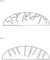
- the porous silicon-based particle according to the embodiment of the present invention includes nonlinear pores as illustrated in FIG. 1 and the nonlinear pores include open pores in the surface of the particle
- the porous silicon-based particle may suppress the volume expansion of an anode active material during charge and/or discharge due to the presence of the open pores in the surface of the particle when used in a lithium secondary battery and may increase a contact area with an electrolyte due to an increase in the specific surface area of the anode active material.
- life characteristics and rate characteristics of the lithium secondary battery including the above anode active material may be improved.
- an average diameter of the open pores is in a range of about 30 nm to about 500 nm, and may be in a range of 30 nm to 300 nm, when observed on the surface of the particle.
- the nonlinear pores may have a nonlinear, corn type structure in which a diameter of the nonlinear pore may gradually decrease in a direction of the center of the porous silicon-based particle.
- At least two or more of the nonlinear pores may be connected to each other.
- a depth of the nonlinear pore may be in a range of 0.1 ⁇ m to 5 ⁇ m.
- the depth of the nonlinear pore denotes a length from the open pore formed at the surface of the porous silicon-based particle to an end of the pore in which the diameter thereof gradually decreases in the direction of the center of the particle, and the depth of the nonlinear pore, for example, may be measured using scanning electron microscope (SEM) images or a mercury porosimeter.
- SEM scanning electron microscope
- a rate of change in volume of mercury intruded into the pore which is measured by mercury porosimetry of the porous silicon-based particles, may have a peak in an average pore diameter range of 30 nm to 2,500 nm, for example, 50 nm to 600 nm.
- a total mercury intrusion volume at the peak may be in a range of 0.5 mL/g to 1.2 mL/g.
- the rate of change in intrusion volume of mercury may have a peak in an average pore diameter range of 30 nm to 2,500 nm from the results of mercury porosimetry measurements denotes that the rate of change in intrusion volume of mercury is distributed so as to have an upward convex curve having a peak in the above average pore diameter range from the results of mercury porosimetry measurements.
- An average particle diameter (D 50 ) of the porous silicon-based particles according to the embodiment of the present invention is in a range of 1 ⁇ m to 20 ⁇ m, may be in a range of 3 ⁇ m to 12 ⁇ m, and for example, may be in a range of 5 ⁇ m to 10 ⁇ m.
- the porous silicon-based particles may be difficult to be dispersed in the anode active material slurry.
- the average particle diameter of the porous silicon-based particles is greater than 20 ⁇ m, since the expansion of the particles due to the charge of lithium ions may become severe, adhesion between particles and adhesion between particles and current collector may decrease as the charge and discharge are repeated. Thus, cycle characteristics may significantly degrade.
- the average particle diameter of the particles may be defined as a particle diameter at 50% in a cumulative particle diameter distribution.
- the average particle diameter (D 50 ) of the particles according to the embodiment of the present invention may be measured by using a laser diffraction method.
- the laser diffraction method may generally measure a particle diameter ranging from a submicron level to a few mm, and may obtain highly repeatable and high resolution results.
- a specific surface area (BET-SSA) of the porous silicon-based particles according to the embodiment of the present invention may be in a range of 5 m 2 /g to 50 m 2 /g, and in the case that a lithium secondary battery is prepared by using the porous silicon-based particles satisfying the above range of the specific surface area as an anode active material, the rate characteristics of the lithium secondary battery may be improved.
- the specific surface area is greater than 50 m 2 /g, the side reactions with the electrolyte may be difficult to be controlled due to the large specific surface area.
- the specific surface area is less than 5 m 2 /g, since pores may not be sufficiently formed, the volume expansion during the charge and discharge with lithium may not be effectively accommodated.
- the specific surface area of the porous silicon-based particles may be measured by a Brunauer-Emmett-Teller (BET) method.
- BET Brunauer-Emmett-Teller
- the specific surface area may be measured by a 6-point BET method according to a nitrogen gas adsorption-flow method using a porosimetry analyzer (Belsorp-II mini by Bell Japan Inc.).
- a porous silicon-based particle including: a core part including Si or SiO x (0 ⁇ x ⁇ 2); and a Si or SiO x shell part including a plurality of nonlinear pores on the core part, wherein a surface of the shell part has open pores.
- a ratio of a length of the core part to a length of the shell part may be in a range of 1:9 to 9:1.
- the shape of the nonlinear pores and open pores according to the embodiment of the present invention and the average diameter of the pores are the same as described above, the shape and average diameter, for example, may be controlled by adjusting the type of a metal catalyst, the concentration of the catalyst, and etching time during the preparation of the porous silicon-based particles.
- a method of preparing porous silicon-based particles according to an embodiment of the present invention may include the steps of: (i) removing an oxide layer present on surfaces of Si or SiO x (0 ⁇ x ⁇ 2) particles using an etching solution; and (ii) forming nonlinear pores in the Si or SiO x (0 ⁇ x ⁇ 2) particles by etching the Si or SiO x (0 ⁇ x ⁇ 2) particles by mixing and stirring the etching solution including the Si or SiO x (0 ⁇ x ⁇ 2) particles with a metal catalyst.
- step (i) may be a step of removing an oxide layer present on surfaces of Si or SiO x (0 ⁇ x ⁇ 2) particles using an etching solution.
- step (i) is a step of removing the oxide layer present on the surfaces of Si or SiO x (0 ⁇ x ⁇ 2) particles, wherein the removing of the oxide layer may be a process of performing a surface treatment so that the Si or SiO x (0 ⁇ x ⁇ 2) particles may be more smoothly and uniformly coated with the metal catalyst using electroless metal deposition.
- the Si or SiO x (0 ⁇ x ⁇ 2) particles are immersed in the etching solution heated to a temperature of about 20°C to about 90°C, and then stirred for about 30 minutes to about 3 hours to remove the natural oxide layer (SiO 2 ) present on the surfaces of the Si or SiO x (0 ⁇ x ⁇ 2) particles.
- the etching solution usable according to an embodiment of the present invention may include at least one solution selected from the group consisting of hydrogen fluoride (HF), hydrofluosilicic acid (H 2 SiF 6 ), and ammonium fluoride (NH 4 F), and for example, the etching solution may be hydrogen fluoride (HF).
- HF hydrogen fluoride
- H 2 SiF 6 hydrofluosilicic acid
- NH 4 F ammonium fluoride
- a concentration of the etching solution may be in a range of 5 M to 20 M.
- step (ii) may be a step of forming nonlinear pores in the Si or SiO x (0 ⁇ x ⁇ 2) particles by etching the Si or SiO x (0 ⁇ x ⁇ 2) particles by mixing and stirring the etching solution including the Si or SiO x (0 ⁇ x ⁇ 2) particles with a metal catalyst.
- the average particle diameter and shape of the pores which may be formed in the Si or SiO x (0 ⁇ x ⁇ 2) particles, may be controlled according to the type and concentration of the metal catalyst and etching (stirring) time.
- a metal is uniformly deposited on the surfaces of the Si or SiO x (0 ⁇ x ⁇ 2) particles through electroless metal deposition and simultaneously, etching is performed by adding the metal catalyst to the etching solution including the Si or SiO x (0 ⁇ x ⁇ 2) particles having the oxide layer removed therefrom, and mixing and stirring the solution.
- etching is performed by adding the metal catalyst to the etching solution including the Si or SiO x (0 ⁇ x ⁇ 2) particles having the oxide layer removed therefrom, and mixing and stirring the solution.
- nonlinear pores may be formed.
- the metal catalyst usable according to an embodiment of the present invention may include any one selected from the group consisting of copper (Cu), platinum (Pt), and nickel (Ni), or two or more elements thereof, and for example, the metal catalyst may include Cu.
- a metal catalyst used in a typical chemical etching method may include silver.
- the metal catalyst including copper, platinum, and nickel there is a similarity in that only a portion contacted with the catalyst is etched.
- the metal catalyst including silver since etching occurs in a direction perpendicular to the surface of a Si or SiO x (0 ⁇ x ⁇ 2) particle as in a schematic view illustrated in FIG. 2 , pores may be linearly formed.
- the metal catalyst including copper, platinum, or nickel according to the embodiment of the present invention since the shape of crystals of the metal catalyst is rectangular, a deposition may occur in the form of a rectangle. Also, since etching is not affected by the crystallinity of Si or SiO x (0 ⁇ x ⁇ 2), the etching may occur in the form of nonlinear pores having no directionality (see FIG. 1 ). Furthermore, since the etching occurs in which an etched portion is in the shape of a corn as it gradually moves into the Si or SiO x (0 ⁇ x ⁇ 2) particles, the average diameter of the nonlinear pores may gradually decrease in the direction of the center of the particle.
- the metal catalyst is not particularly limited so long as it includes the above metal element, but may be in the form of a salt including the above metal.
- an anion of the salt may include any one selected from the group consisting of nitric acid (NO 3 - ), sulfuric acid (SO 4 2- ), iodine (I - ), perchlorate (ClO 4 - ), and acetic acid (CH 3 COO - ), or a mixture of two or more thereof.
- a concentration of the metal catalyst may be in a range of 5 mM to 100 mM.
- the etching (stirring) time may be in a range of about 3 hours to about 24 hours, and the formation degree of the nonlinear pores may be changed by the etching time.
- the etching time is less than 3 hours, since the desired pores of the present invention may not be formed, the desired effect of the present invention may not be obtained.
- the etching time is greater than 24 hours, since the etching does not occur anymore due to the consumption of the etching solution, processing time only increases and there is no effect due to the etching time. Also, since cracks are observed on the surfaces of the porous silicon-based particles and the Si or SiO x (0 ⁇ x ⁇ 2) particles are over-etched, mechanical properties of the anode active material may deteriorate.
- the deposition of the metal catalyst may be performed for about 1 hour to about 12 hours. Also, in terms of process efficiency such as time and costs, both the deposition of the metal catalyst and the etching may be simultaneously performed by mixing and stirring the etching solution including the Si or SiO x (0 ⁇ x ⁇ 2) particles having the oxide layer removed therefrom with the metal catalyst.
- a weak oxidant may be further added to the etching solution in step (ii).
- the weak oxidant may increase a chemical etching rate, may further form additional pores through the oxidation of silicon, and may promote the etching in order for the pores to be connected one another.
- the weak oxidant may increase the average diameter of the pores formed by the metal catalyst.
- the silicon along with the metal may be vertically etched. Thus, it may be difficult to form the desired nonlinear pores of the present invention.
- the weak oxidant usable according to the embodiment of the present invention may include any one selected from the group consisting of phosphite, sulfite, and phosphate, or a mixture of two or more thereof.
- phosphite may be used and a concentration of the weak oxidant may be in a range of 0.25 M to 1.0 M.
- removing the metal catalyst remaining in the particles may be further included.
- the Si or SiO x (0 ⁇ x ⁇ 2) particles having the nonlinear pores formed therein may be in contact with a metal removal solution to remove the metal catalyst.
- the metal removal solution used may include any one selected from the group consisting of nitric acid (HNO 3 ), sulfuric acid (H 2 SO 4 ), and hydrochloric acid (HCl), or a mixture of two or more thereof.
- the porous silicon-based particle may further include a carbon coating layer on the porous silicon-based particle.
- a method of forming the carbon coating layer may be a typical coating method using a carbon precursor and, for example, after the etching, the method of forming the carbon coating layer may further include coating outer surfaces of the porous silicon-based particles with carbon by mixing the porous silicon-based particles with a carbon precursor and then performing a heat treatment.
- Any carbon precursor may be used without limitation so long as it may form carbon by a heat treatment, and for example, pitch or a hydrocarbon-based material may be used.
- the hydrocarbon-based material may be furfuryl alcohol or a phenol-based resin.
- the carbon precursor may be used in an amount of 10 wt% to 40 wt% based on a total weight of the porous silicon-based particles.
- the carbon precursor is used in an amount of less than 10 wt%, since a uniform coating layer may not be formed, electrical conductivity may be reduced. In the case in which the carbon precursor is used in an amount of greater than 40 wt%, since surface pores and inner pores of the porous silicon-based particles may be entirely coated with a carbon material, a performance improvement effect caused by a porous structure may not be obtained and capacity and initial efficiency may be reduced due to the occurrence of an additional irreversible reaction.
- tetrahydrofuran (THF) and alcohol may be used as a solvent for forming the carbon coating layer, and the coating may be performed by performing a heat treatment in a temperature range of 300°C to 1,400°C.
- a porosity of the porous silicon-based particle according to the embodiment of the present invention is in a range of 5% to 90%, may be in a range of 10% to 70%, and for example, may be in a range of 10% to 40% based on a total volume of the porous silicon-based particle.
- the measurement of the porosity is not particularly limited.
- the porosity for example, may be measured by a BET method or mercury (Hg) porosimetry.
- the porosity of the porous silicon-based particle is less than 5%, the volume expansion of the anode active material during charge and discharge may not be suppressed.
- the porosity of the porous silicon-based particle is greater than 90%, mechanical strength may be decreased due to a plurality of pores included in the anode active material, and thus, the anode active material may be fractured during manufacturing processes (slurry mixing, pressing after coating, etc.) of a battery.
- the present invention may provide an anode active material including the porous silicon-based particles.
- the anode active material according to an embodiment of the present invention may further include a carbon-based material. That is, the anode active material may be used in a secondary battery by mixing the porous silicon-based particles with a typically used carbon-based material.
- the typically used carbon-based material may be at least one selected from the group consisting of natural graphite, artificial graphite, meso-carbon microbeads (MCMB), carbon fibers, and carbon black.
- MCMB meso-carbon microbeads
- the carbon-based material may be included in an amount of 0 parts by weight to 90 parts by weight, for example, 70 parts by weight to 95 parts by weight based on 100 parts by weight of the porous silicon-based particles.
- the present invention may also provide an anode including the anode active material.
- the present invention may provide a lithium secondary battery including a cathode, an anode, a separator disposed between the cathode and the anode, and an electrolyte in which a lithium salt is dissolved, wherein the anode includes an anode active material including the porous silicon-based particles.
- the anode active material thus prepared may be used to prepare an anode by a typical method in the art.
- the anode active material according to the embodiment of the present invention is mixed with a binder, a solvent, and a conductive agent and a dispersant if necessary, and stirred to prepare a slurry.
- a current collector may be coated with the slurry and pressed to prepare an anode.
- binder polymers such as a polyvinylidene fluoride-hexafluoropropylene copolymer (PVDF-co-HEP), polyvinylidene fluoride, polyacrylonitrile, polymethylmethacrylate, polyvinyl alcohol, carboxymethyl cellulose (CMC), starch, hydroxypropyl cellulose, regenerated cellulose, polyvinylpyrrolidone, tetrafluoroethylene, polyethylene, polypropylene, an ethylene-propylene-diene monomer (EPDM), a sulfonated EPDM, a styrene-butadiene rubber (SBR), a fluorine rubber, poly acrylic acid, and a polymer having hydrogen thereof substituted with lithium (Li), sodium (Na), and calcium (Ca), or various copolymers, may be used as the binder.
- N-methyl pyrrolidone, acetone, or water may be used as the solvent.
- the conductive agent may include a conductive material such as: graphite such as natural graphite and artificial graphite; carbon black such as acetylene black, Ketjen black, channel black, furnace black, lamp black, and thermal black; conductive fibers such as carbon fibers and metal fibers; conductive tubes such as carbon nanotubes; metal powder such as fluorocarbon powder, aluminum powder, and nickel powder; conductive whiskers such as zinc oxide whiskers and potassium titanate whiskers; conductive metal oxide such as titanium oxide; or polyphenylene derivatives.
- a conductive material such as: graphite such as natural graphite and artificial graphite; carbon black such as acetylene black, Ketjen black, channel black, furnace black, lamp black, and thermal black; conductive fibers such as carbon fibers and metal fibers; conductive tubes such as carbon nanotubes; metal powder such as fluorocarbon powder, aluminum powder, and nickel powder; conductive whiskers such as zinc oxide whiskers and potassium titanate whiskers; conductive metal oxide such as titanium
- An aqueous-based dispersant or an organic dispersant, such as N-methyl-2-pyrrolidone, may be used as the dispersant.
- a cathode active material, a conductive agent, a binder, and a solvent are mixed to prepare a slurry, and a cathode may then be prepared by directly coating a metal current collector with the slurry or by casting the slurry on a separate support and laminating a cathode active material film separated from the support on a metal current collector.
- a typical porous polymer film used as a typical separator for example, a porous polymer film prepared from a polyolefin-based polymer, such as an ethylene homopolymer, a propylene homopolymer, an ethylene/butene copolymer, an ethylene/hexene copolymer, and an ethylene/methacrylate copolymer, may be used alone or in a lamination therewith as the separator.
- a typical porous nonwoven fabric for example, a nonwoven fabric formed of high melting point glass fibers or polyethylene terephthalate fibers, and a polymer separator base material having at least one surface thereof coated with ceramic may be used.
- the present invention is not limited thereto.
- a lithium salt which may be included as the electrolyte, may be used without limitation so long as it is typically used in an electrolyte solution for a secondary battery.
- a lithium salt which may be included as the electrolyte, may be used without limitation so long as it is typically used in an electrolyte solution for a secondary battery.
- an organic solvent included in the electrolyte solution may be used without limitation so long as it is typically used in the art.
- ethylene carbonate and propylene carbonate, ring-type carbonates among the carbonate-based organic solvents, well dissociate the lithium salt in the electrolyte due to high dielectric constants as high-viscosity organic solvents, and thus, the ring-type carbonate may be used. Since an electrolyte having high electrical conductivity may be prepared when the ring-type carbonate is mixed with low-viscosity, low-dielectric constant linear carbonate, such as dimethyl carbonate and diethyl carbonate, in an appropriate ratio, the ring-type carbonate, for example, may be used.
- the electrolyte stored according to the present invention may further include an additive, such as an overcharge inhibitor, that is included in a typical electrolyte.
- an additive such as an overcharge inhibitor
- a separator is disposed between the cathode and the anode to form an electrode assembly, the electrode assembly is put in a cylindrical battery case or prismatic battery case or aluminum pouch, and a secondary battery is then completed when the electrolyte is injected thereinto. Also, the electrode assembly is stacked and impregnated with the electrolyte solution, and a lithium secondary battery is then completed when the product thus obtained is put in a battery case and sealed.
- the lithium secondary battery according to the present invention may not only be used in a battery cell that is used as a power source of a small device, but may also be used as a unit cell in a medium and large sized battery module including a plurality of battery cells.
- Preferred examples of the medium and large sized device may be an electric vehicle, a hybrid electric vehicle, a plug-in hybrid electric vehicle, or a power storage system, but the medium and large sized device is not limited thereto.
- Silicon in a powder state was immersed in 8.5 M hydrogen fluoride heated to a temperature of 50°C, and then stirred for about 30 minutes.
- a natural oxide layer (SiO 2 ) present on the surface of the silicon in a powder state was removed through the above process.
- silicon particles having the oxide layer removed therefrom were obtained by performing a surface treatment which may allow the Si or SiO x (0 ⁇ x ⁇ 2) particles to be more smoothly and uniformly coated with the metal catalyst using electroless metal deposition.
- a 15 mM copper sulfate (CuSO 4 ) aqueous solution prepared at the same volume as that of the hydrogen fluoride was added to an aqueous solution including silicon having the oxide layer (SiO 2 ) removed therefrom that was obtained in step (i), in which 8.5 M hydrogen fluoride was mixed, and stirred for about 3 hours to perform etching. Copper was deposited on the surface of the silicon having the oxide layer (SiO 2 ) removed therefrom through the above process, and simultaneously, the etching was performed.
- the remaining hydrogen fluoride was removed by washing porous silicon particles several times using a filter press capable of simultaneously filtering, washing, and dehydrating. Thereafter, the solution thus obtained was filtered, dehydrated, and dried at about 150°C for about 1 hour to obtain porous silicon particles in which nonlinear pores were connected to one another.
- nitric acid was heated to a temperature of 50°C, and the porous silicon particles were then immersed in the nitric acid for about 2 hours to remove the copper.
- Porous silicon particles were prepared in the same manner as in Example 1 except that a 15 mM copper sulfate (CuSO 4 ) aqueous solution prepared at the same volume as that of the hydrogen fluoride was added to an aqueous solution including silicon having the oxide layer (SiO 2 ) removed therefrom that was obtained in step (i), in which 8.5 M hydrogen fluoride was mixed, and stirred for about 6 hours, 9 hours, 12 hours, 18 hours, and 24 hours, respectively.
- CuSO 4 copper sulfate
- Silicon in a powder state was immersed in 17.5 M hydrogen fluoride heated to a temperature of 50°C, and then stirred for about 30 minutes.
- a natural oxide layer (SiO 2 ) present on the surface of the silicon in a powder state was removed through the above process.
- silicon particles having the oxide layer removed therefrom were obtained by performing a surface treatment which may allow the Si or SiO x (0 ⁇ x ⁇ 2) particles to be more smoothly and uniformly coated with the metal catalyst using electroless metal deposition.
- a 30 mM copper sulfate (CuSO 4 ) aqueous solution prepared at the same volume as that of the hydrogen fluoride was added to an aqueous solution, in which 17.5 M hydrogen fluoride and silicon having the oxide layer (SiO 2 ) removed therefrom that was obtained in step (i) were mixed, and stirred for about 1 hour. Copper was uniformly deposited on the surface of the silicon having the oxide layer (SiO 2 ) removed therefrom through the above process.
- aqueous solution including silicon having the oxide layer (SiO 2 ) removed therefrom in which 17.5 M hydrogen fluoride was mixed a 0.5 M phosphite (H 3 PO 3 ) aqueous solution was prepared to have 1/3 of the volume of the hydrogen fluoride, and was then added to the aqueous solution including the copper-deposited silicon that was obtained in the above metal deposition step.
- this mixture was mixed at 50°C for about 21 hours, a portion deposited with copper and a surface oxidized by phosphite were only selectively etched by chemical etching, and thus, porous silicon was prepared in which nonlinear pores were connected to one another.
- the copper deposited on the silicon was used as a catalyst reducing silicon and the phosphite was used as a weak oxidant oxidizing the silicon to increase a chemical etching rate.
- the phosphite used as a weak oxidant may increase the size of the pore formed by the copper or may form additional pores through the oxidation of the silicon.
- Porous silicon particles were prepared in the same manner as in Example 1 except that a silver nitrate aqueous solution was used instead of a copper sulfate (CuSO 4 ) aqueous solution in step (ii) of Example 1.
- a silver nitrate aqueous solution was used instead of a copper sulfate (CuSO 4 ) aqueous solution in step (ii) of Example 1.
- Porous silicon particles were prepared in the same manner as in Example 7 except that an iron nitrate (Fe(NO 3 ) 3 ) (or other strong oxidants) was used instead of a 0.5 M phosphite (H 3 PO 3 ) aqueous solution in step (ii) of Example 7.
- Fe(NO 3 ) 3 iron nitrate
- H 3 PO 3 0.5 M phosphite
- Porous silicon particles were prepared in the same manner as in Example 1 except that etching was performed for 28 hours in step (ii) of Example 1.
- Porous silicon particles were prepared in the same manner as in Example 1 except that etching was performed for 1 hour in step (ii) of Example 1.
- the porous silicon-based particles prepared in Example 1 were used as an anode active material.
- the anode active material, acetylene black as a conductive agent, and polyvinylidene fluoride as a binder were mixed at a weight ratio of 70:10:20, and the mixture was mixed with a N-methyl-2-pyrrolidone solvent to prepare a slurry.
- One surface of a copper current collector was coated with the prepared slurry to a thickness of 30 pm, dried, and rolled. Then, an anode was prepared by punching into a predetermined size.
- a mixed solvent which includes 1.0 M LiPF 6 and an organic solvent prepared by mixing ethylene carbonate and diethyl carbonate at a weight ratio of 30:70, to prepare a non-aqueous electrolyte solution.
- a lithium foil was used as a counter electrode, a polyolefin separator was disposed between both electrodes, and a coin-type half cell was then prepared by injecting the electrolyte solution.
- a coin-type half cell was prepared in the same manner as in Example 8 except that the porous silicon particles prepared in Example 5 were coated with 10 wt% of carbon and an anode active material was used in which the carbon-coated porous silicon particles and graphite were mixed at a ratio of 50:50.
- a coin-type half cell was prepared in the same manner as in Example 8 except that pure Si particles were used as an anode active material instead of using the porous silicon-based particles prepared in Example 1.
- a coin-type half cell was prepared in the same manner as in Example 8 except that the porous silicon particles prepared in Comparative Example 4 were coated with 10 wt% of carbon and an anode active material was used in which the carbon-coated porous silicon particles and graphite were mixed at a ratio of 50:50.
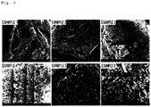
- pores were formed in the surface of the porous silicon-based particle of Example 1 in which the etching was performed for 3 hours, and the formation degree and diameter of the pores, which were formed in the particle, tended to increase as the etching time increased to 6 hours, 9 hours, 12 hours, 18 hours, and 24 hours as in Examples 2 to 6.
- Example 6 With respect to Example 6 in which the etching was performed for about 24 hours, it may be confirmed that the nonlinear pores included in the porous silicon particles were almost connected to one another, and it was also confirmed that a depth of the pore was the largest in Example 6 in which the etching was performed for about 24 hours.
- the depth of the nonlinear pore of the particle was increased because the size of copper, as a metal catalyst, deposited on the surface of silicon was increased by hydrogen fluoride as the etching time increased.
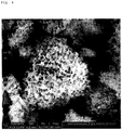
- FIG. 5 is an electron microscope image showing an internal cross-section of the porous silicon particle obtained in Example 7 after sectioning.
- the porous silicon particle was cross-sectioned using an argon (Ar)-ion milling apparatus and the internal cross-section was then analyzed with an electron microscope.
- pores of the porous silicon particle prepared in Example 7 were formed up to the inside of the particle, and it may be confirmed that the nonlinear pores having no directionality were connected to one another in the porous silicon particle.
- the average diameter of the internal pores tended to be gradually decreased in the direction of the center of the particle in comparison to the surface of the porous silicon particle due to the additional pore formation and the active connection between the pores by the phosphite.
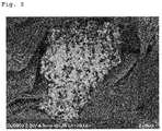
- FIG. 6 illustrating an internal cross-section of the silicon-based particle prepared in Example 1, it may be confirmed that since the etching occurred in a direction perpendicular to the surface of the silicon, pores may be linearly formed.
- porous silicon-based particles obtained in Examples 1 to 6 were respectively charged into a container and, as the tap density of the particles, an apparent density of the particles was measured by vibrating under a predetermined condition.
- the total mercury intrusion volumes (mL/g) were measured by using a mercury porosimeter (AutoPore VI 9500, Micromerities, USA).
- the mercury porosimetry uses a capillary phenomenon by which a liquid infiltrates into a fine pore.
- a non-wetting liquid such as mercury, can infiltrate when a pressure is applied from the outside, and the smaller the size of the pore is, the higher the pressure is required.
- the measurement results may be represented by a function of a cumulative volume of mercury intruded according to the pressure (or size of the pore).
- Porous silicon particles were put in a penetrometer and sealed, and a vacuum was then applied and mercury was filled.
- the pressure was applied to the penetrometer, the mercury infiltrated into the pores of the porous silicon particles to reduce the height of the mercury of the penetrometer.
- the reduction was measured as a function of the pressure, the volume of the mercury infiltrated into the pores may be obtained.
- the mercury intrusion results may be represented by a pore radius or intrusion pressure and a cumulative intrusion volume per sample weight.
- a cumulative intrusion curve may be a bimodal curve due to these pores.
- the bulk density of the porous silicon-based particles may be obtained by using a total intrusion volume when the pressure was maximum during the mercury porosimetry, i.e., when the mercury intrusion did not occur anymore.
- porosities of the porous silicon-based particles of Examples 1 to 6, in which nonlinear pores were formed by etching for 3 hours to 24 hours were in a range of about 11% to about 39%.
- the porosity was close to about 40% in comparison to pure Si particles in which a treatment for forming pores was not performed.
- the Si particles had a tap density of 1.02 (g/cc) and a bulk density of 0.85 (g/cc).
- the porous silicon-based particles of Examples 1 to 6 had lower tap densities and bulk densities than the above tap density and bulk density.
- a total mercury intrusion volume of the Si particles was 0.53 g/cc and total mercury intrusion volumes of the porous silicon-based particles of Examples 1 to 6 were in a range of 0.64 g/cc to 1.19 g/cc.
- the total mercury intrusion volumes of the porous silicon-based particles of Examples 1 to 6 were significantly increased in comparison to that of the Si particles.
- the total mercury intrusion volumes were respectively 1.05 g/cc and 1.19 g/cc.
- the total mercury intrusion volumes were increased by 2 times or more in comparison to that of the Si particles.
- Example 7 In order to identify physical properties of the porous silicon particles obtained in Example 7 in which the etching was performed by using the weak oxidant, tap density (g/cc), BET specific surface area (m 2 /g), and particle size distribution were measured, and the results thereof are presented in Table 2 below.
- the tap density measurement was performed in the same manner as in the porous silicon-based particles of Examples 1 to 6.
- the specific surface area of the porous silicon-based particles of Example 7 may be measured by a BET method.
- the specific surface area was measured by a 6-point BET method according to a nitrogen gas adsorption-flow method using a porosimetry analyzer (Belsorp-II mini by Bell Japan Inc.).
- D min , D 10 , D 50 , D 90 , and D max were measured as an average particle size distribution of the porous silicon-based particles for the particle size distribution of the porous silicon-based particles of Example 7, and D min , D 10 , D 50 , D 90 , and D max were denoted as particle diameters at less than 10%, 10%, 50%, 90%, and greater than 90% in a cumulative particle diameter distribution, respectively.
- the particle size distribution of the porous silicon-based particles of Example 7 was measured by using a laser diffraction method (Microtrac MT 3000).
- Example 7 0.61 20.87 2.312 3.55 4.63 6.14 10.09 Si particles 1.02 1.56 2.312 3.57 4.65 6.15 10.09
- tap density of the porous silicon particles obtained in Example 7 was 0.61 g/cc and tap density of the Si particles was 1.02 g/cc. Thus, it may be confirmed that the tap density of the porous silicon particles of Example 7 was decreased by about 0.41 g/cc in comparison to that of the Si particles.
- a BET specific surface area of the porous silicon particles obtained in Example 7 was 20.87 m 2 /g, and a BET specific surface area of the Si particles was 1.56 m 2 /g.
- the BET specific surface area of the porous silicon particles prepared in Example 7 was increased by about 13 times in comparison to that of the Si particles.
- Example 7 and the Si particles exhibited the same particle size distribution, it was considered that the increase in the specific surface area was due to the formation of the pores.
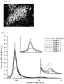
- FIG. 7 illustrates pore distributions of the porous silicon-based particles prepared in Examples 1 to 6 through mercury porosimetry analysis.
- a rate of change in volume of mercury intruded into the pore which was measured by mercury porosimetry of the porous silicon-based particles, had peaks in an average pore diameter range of about 30 nm to about 2,500 nm.
- the peaks respectively appeared in average pore diameter ranges of 800 nm to 2,000 nm and 50 nm to 600 nm.
- the peak in an average pore diameter range of 800 nm to 2,000 nm was a peak corresponding to pores between the porous silicon particles and the peak in an average pore diameter range of 50 nm to 600 nm was a peak corresponding to the nonlinear pores included in the porous silicon particles.
- a total mercury intrusion volume in the average pore diameter range of 50 nm to 600 nm was in a range of 0.5 mL/g to 1.2 mL/g.
- the pore volume was increased as the etching time was increased to 3 hours, 6 hours, 9 hours, 12 hours, 18 hours, and 24 hours as in Examples 1 to 6.
- the porous silicon particles of Example 6, in which the etching was performed for 24 hours exhibited the largest pore volume.
- the average diameter distribution of the pores was in a form in which mesopores having an average diameter of 20 nm to 100 nm and macropores coexisted until the etching time was in a range of 3 hours to 18 hours, and the distribution of macropores having an average diameter of 50 nm or more was increased as the etching time increased. This was considered due to the fact that the formed pores were connected to one another as the etching time increased.
- the porous silicon particles of Example 5 which were etched for 18 hours, had a pore distribution in which macropores having an average diameter of 50 nm or more were mostly formed.
- porous silicon particles of Example 6 which were etched for 24 hours, had a pore shape in which pores were almost combined and connected to one another.
- Life characteristics of each secondary battery were measured by performing charge and discharge at 0.1 C in a first cycle and performing charge and discharge at 0.5 C in subsequent cycles. The life characteristics were represented as a ratio of discharge capacity in a 49th cycle to the first cycle discharge capacity. Each secondary battery was disassembled in a charge state of a 50th cycle and a thickness of an electrode was measured. Then, a thickness change rate was obtained by comparing the above thickness with a thickness of the electrode before the first cycle.
- Table 3 presents life characteristics and thickness change rates of the secondary batteries prepared in Examples 8 to 15 and Comparative Examples 5 to 10.
- Example 8 when particularly comparing Example 8 and Comparative Example 6 in which the etching was performed for 3 hours, it may be confirmed that the thickness change rate of Example 8 using the copper sulfate aqueous solution as a metal catalyst was decreased in comparison to that of Comparative Example 6 using silver nitrate.
- Example 14 when comparing Example 14 and Comparative Example 7 in which the etching was performed for 21 hours, it may be confirmed that both the life characteristics and the thickness change rate of Example 14 using phosphite as a weak oxidant were better than those of Comparative Example 7 using iron nitrate as a strong oxidant.
- the thickness change rate was 300%, and thus, it may be confirmed that the volume expansion was not reduced due to the insufficient formation of the pores.
- Porous silicon-based particles according to an embodiment of the present invention may be more easily dispersed in an anode active material slurry, may minimize side reactions with an electrolyte, and may reduce volume expansion during charge and discharge by including Si or SiO x (0 ⁇ x ⁇ 2) particles having a plurality of nonlinear pores.
- the porous silicon-based particles may be suitable for a secondary battery.
Claims (39)
- Particule à base de silicium poreux comprenant une particule de silicium (Si) ou de SiOx(O<x<2),
dans laquelle la particule comprend une pluralité de pores non linéaires, et
les pores non linéaires sont formés comme des pores ouverts dans une surface de la particule. - Particule à base de silicium poreux selon la revendication 1, dans laquelle au moins deux des pores non linéaires ou plus sont reliés les uns aux autres.
- Particule à base de silicium poreux selon la revendication 1, dans laquelle un diamètre moyen des pores non linéaires diminue progressivement dans une direction d'un centre de la particule.
- Particule à base de silicium poreux selon la revendication 1, dans laquelle un diamètre moyen des pores ouverts à la surface est dans une plage d'environ 30 nm à environ 500 nm.
- Particule à base de silicium poreux selon la revendication 1, dans laquelle un taux de changement de volume de mercure introduit dans le pore, qui est mesuré par porosimétrie au mercure des particules à base de silicium poreux, présente un pic dans une plage de diamètre de pore moyen de 30 nm à 2500 nm.
- Particule à base de silicium poreux selon la revendication 5, dans laquelle le taux de changement de volume de mercure présente un pic dans une plage de diamètre de pore moyen de 50 nm à 600 nm.
- Particule à base de silicium poreux selon la revendication 5, dans laquelle un volume d'intrusion de mercure total au pic est dans une plage de 0,5 mL/g à 1,2 mL/g.
- Particule à base de silicium poreux selon la revendication 1, dans laquelle une surface spécifique (SSA-BET (Brunauer-Emmett-Teller)) des particules à base de silicium poreux est dans une plage de 5 m2/g à 50 m2/g.
- Particule à base de silicium poreux selon la revendication 1, dans laquelle une profondeur du pore non linéaire est dans une plage de 0,1 µm à 5 µm.
- Particule à base de silicium poreux selon la revendication 1, dans laquelle un diamètre de particule moyen (D50) des particules à base de silicium poreux est dans la plage de 1 µm à 20 µm.
- Particule à base de silicium poreux comprenant :une partie de coeur incluant du silicium (Si) ou SiOx(0<x<2) ; etune partie d'enveloppe en Si ou SiOx incluant une pluralité de pores non linéaires sur la partie de coeur,dans laquelle une surface de la partie d'enveloppe présente des pores ouverts.
- Particule à base de silicium poreux selon la revendication 11, dans laquelle un rapport d'une longueur de la partie de coeur sur une longueur de la partie d'enveloppe est dans une plage de 1:9 à 9:1.
- Particule à base de silicium poreux selon la revendication 11, dans laquelle au moins deux des pores non linéaires ou plus sont reliés les uns aux autres.
- Particule à base de silicium poreux selon la revendication 11, dans laquelle un diamètre moyen du pore diminue progressivement dans une direction d'un centre de la particule.
- Particule à base de silicium poreux selon la revendication 11, dans laquelle un diamètre moyen des pores ouverts est dans une plage d'environ 30 nm à environ 500 nm.
- Particule à base de silicium poreux selon la revendication 1 ou 11, comprenant en outre une couche de revêtement de carbone sur la particule à base de silicium poreux.
- Particule à base de silicium poreux selon la revendication 1 ou 11, dans laquelle une porosité de la particule à base de silicium poreux est dans une plage de 5 % à 90 % sur la base d'un volume total de la particule à base de silicium poreux.
- Particule à base de silicium poreux selon la revendication 1 ou 11, dans laquelle une porosité de la particule à base de silicium poreux est dans une plage de 10 % à 70 % sur la base d'un volume total de la particule à base de silicium poreux.
- Matériau actif d'anode comprenant les particules à base de silicium poreux selon la revendication 1 ou 11.
- Matériau actif d'anode selon la revendication 19, comprenant en outre un matériau à base de carbone.
- Matériau actif d'anode selon la revendication 20, dans lequel le matériau à base de carbone comprend au moins un matériau choisi dans le groupe constitué de graphite naturel, de graphite artificiel, de microbilles de mésocarbone (MBMC), de fibres de carbone et de noir de carbone.
- Matériau actif d'anode selon la revendication 20, dans lequel le matériau à base de carbone est inclus dans une quantité de 0 partie en poids à 90 parties en poids sur la base de 100 parties en poids des particules à base de silicium poreux.
- Procédé de préparation des particules à base de silicium poreux selon la revendication 1, le procédé comprenant les étapes suivantes :(i) élimination d'une couche d'oxyde présente sur les surfaces de particules de silicium (Si) ou de SiOx(0<x<2) à l'aide d'une solution d'attaque ; et(ii) formation de pores non linéaires dans les particules de Si ou de SiOx(0<x<2) par attaque des particules de Si ou de SiOx(0<x<2) par ajout d'un catalyseur métallique à la solution d'attaque incluant les particules de Si ou SiOx(0<x<2) dont la couche d'oxyde a été éliminée, et mélange et agitation de la solution.
- Procédé selon la revendication 23, dans lequel le catalyseur métallique comprend l'un quelconque choisi dans le groupe constitué de cuivre (Cu), platine (Pt) et nickel (Ni), ou deux éléments ou plus de celui-ci.
- Procédé selon la revendication 23, dans lequel l'élimination de la couche d'oxyde est effectuée dans une plage de température de 20 °C à 90 °C pendant 30 minutes à 3 heures.
- Procédé selon la revendication 23, dans lequel la solution d'attaque comprend au moins une solution choisie dans le groupe constitué du fluorure d'hydrogène (HF), de l'acide hydrofluorosilicique (H2SiF6) et du fluorure d'ammonium (NH4F).
- Procédé selon la revendication 23, dans lequel une concentration de la solution d'attaque est dans une plage de 5 M à 20 M.
- Procédé selon la revendication 23, dans lequel une concentration du catalyseur métallique est dans une plage de 5 mM à 100 mM.
- Procédé selon la revendication 28, dans lequel un dépôt du catalyseur métallique est effectué pendant 1 heure à 12 heures.
- Procédé selon la revendication 23, comprenant en outre l'ajout d'un oxydant faible à l'étape (ii).
- Procédé selon la revendication 30, dans lequel l'oxydant faible comprend l'un quelconque choisi dans le groupe constitué de phosphite, sulfite et phosphate, ou d'un mélange de deux ou plus de ceux-ci.
- Procédé selon la revendication 30, dans lequel une concentration de l'oxydant faible est dans une plage de 0,25 M à 1,0 M.
- Procédé selon la revendication 23, dans lequel l'attaque est effectuée pendant 3 heures à 24 heures.
- Procédé selon la revendication 23, comprenant en outre le revêtement de surfaces externes des particules à base de silicium poreux avec du carbone en mélangeant les particules à base de silicium poreux avec un précurseur de carbone et en effectuant un traitement thermique, après l'attaque.
- Procédé selon la revendication 34, dans lequel le précurseur de carbone comprend du brai ou un matériau à base d'hydrocarbure.
- Procédé selon la revendication 34, dans lequel le précurseur de carbone est utilisé dans une quantité de 10 % en poids à 40 % en poids sur la base d'un poids total des particules à base de silicium poreux.
- Procédé selon la revendication 34, dans lequel le traitement thermique est effectué dans une plage de température de 300 °C à 1400 °C.
- Anode comprenant le matériau actif d'anode selon la revendication 19.
- Batterie secondaire au lithium comprenant l'anode selon la revendication 38.
Priority Applications (1)
| Application Number | Priority Date | Filing Date | Title |
|---|---|---|---|
| PL14814680T PL2873646T3 (pl) | 2013-09-02 | 2014-08-29 | Porowate cząstki na bazie krzemu, sposób ich wytwarzania i zawierający je materiał czynny anody |
Applications Claiming Priority (3)
| Application Number | Priority Date | Filing Date | Title |
|---|---|---|---|
| KR20130104877 | 2013-09-02 | ||
| KR1020140112617A KR101636143B1 (ko) | 2013-09-02 | 2014-08-27 | 다공성 실리콘계 입자, 이의 제조 방법, 및 이를 포함하는 음극 활물질 |
| PCT/KR2014/008093 WO2015030531A1 (fr) | 2013-09-02 | 2014-08-29 | Particules à base de silicium poreux, leur procédé de préparation et substance active d'anode les comprenant |
Publications (3)
| Publication Number | Publication Date |
|---|---|
| EP2873646A1 EP2873646A1 (fr) | 2015-05-20 |
| EP2873646A4 EP2873646A4 (fr) | 2015-10-14 |
| EP2873646B1 true EP2873646B1 (fr) | 2019-04-03 |
Family
ID=52586982
Family Applications (1)
| Application Number | Title | Priority Date | Filing Date |
|---|---|---|---|
| EP14814680.6A Active EP2873646B1 (fr) | 2013-09-02 | 2014-08-29 | Particules à base de silicium poreux, leur procédé de préparation et substance active d'anode les comprenant |
Country Status (4)
| Country | Link |
|---|---|
| US (1) | US9947922B2 (fr) |
| EP (1) | EP2873646B1 (fr) |
| PL (1) | PL2873646T3 (fr) |
| WO (1) | WO2015030531A1 (fr) |
Families Citing this family (33)
| Publication number | Priority date | Publication date | Assignee | Title |
|---|---|---|---|---|
| GB2492167C (en) | 2011-06-24 | 2018-12-05 | Nexeon Ltd | Structured particles |
| WO2013114094A1 (fr) | 2012-01-30 | 2013-08-08 | Nexeon Limited | Composition de matière électroactive à base de si/c |
| GB2499984B (en) | 2012-02-28 | 2014-08-06 | Nexeon Ltd | Composite particles comprising a removable filler |
| GB2502625B (en) | 2012-06-06 | 2015-07-29 | Nexeon Ltd | Method of forming silicon |
| GB2507535B (en) | 2012-11-02 | 2015-07-15 | Nexeon Ltd | Multilayer electrode |
| WO2015045316A1 (fr) * | 2013-09-24 | 2015-04-02 | 三洋電機株式会社 | Matériau actif d'électrode négative pour batteries rechargeables à électrolyte non aqueux et batterie rechargeable à électrolyte non aqueux utilisant ce dernier |
| KR101567203B1 (ko) | 2014-04-09 | 2015-11-09 | (주)오렌지파워 | 이차 전지용 음극 활물질 및 이의 방법 |
| KR101604352B1 (ko) | 2014-04-22 | 2016-03-18 | (주)오렌지파워 | 음극 활물질 및 이를 포함하는 리튬 이차 전지 |
| GB2529410A (en) * | 2014-08-18 | 2016-02-24 | Nexeon Ltd | Electroactive materials for metal-ion batteries |
| GB2533161C (en) | 2014-12-12 | 2019-07-24 | Nexeon Ltd | Electrodes for metal-ion batteries |
| KR101726037B1 (ko) | 2015-03-26 | 2017-04-11 | (주)오렌지파워 | 실리콘계 음극 활물질 및 이의 제조 방법 |
| KR101826391B1 (ko) | 2015-03-31 | 2018-02-06 | 주식회사 엘지화학 | 다공성 실리콘-실리콘옥사이드-탄소 복합체, 및 이의 제조방법 |
| KR102573163B1 (ko) | 2015-08-21 | 2023-08-30 | 삼성전자주식회사 | 이미지 센서 및 이를 포함하는 전자 장치 |
| KR101997746B1 (ko) | 2015-09-24 | 2019-07-08 | 삼성전자주식회사 | 전지 팩 및 이의 충/방전 제어 방법 |
| KR101981609B1 (ko) * | 2015-09-24 | 2019-05-24 | 주식회사 엘지화학 | 리튬 이차전지용 음극활물질 및 그 제조방법 |
| KR102048343B1 (ko) * | 2016-05-27 | 2019-11-25 | 주식회사 엘지화학 | 음극활물질 및 이를 포함하는 리튬 이차전지 |
| ES2953371T3 (es) | 2016-06-02 | 2023-11-10 | Lg Energy Solution Ltd | Material activo de cátodo, cátodo que comprende el mismo, y batería secundaria de litio que comprende el mismo |
| EP4167312A3 (fr) * | 2016-06-14 | 2023-05-03 | Nexeon Limited | Électrodes pour batteries métal-ion |
| KR101918815B1 (ko) | 2016-08-23 | 2018-11-15 | 넥시온 엘티디. | 이차 전지용 음극 활물질 및 이의 제조 방법 |
| KR101773719B1 (ko) | 2016-08-23 | 2017-09-01 | (주)오렌지파워 | 2 차 전지용 실리콘계 활물질 입자 및 이의 제조 방법 |
| US20180076458A1 (en) * | 2016-09-09 | 2018-03-15 | Bayerische Motoren Werke Aktiengesellschaft | Porous Silicon Materials and Conductive Polymer Binder Electrodes |
| US10930933B2 (en) | 2016-09-09 | 2021-02-23 | Bayerische Motoren Werke Aktiengesellschaft | Conductive polymer binder for a novel silicon/graphene anode in lithium ion batteries |
| GB201803983D0 (en) | 2017-09-13 | 2018-04-25 | Unifrax I Llc | Materials |
| CN110867576A (zh) * | 2018-08-28 | 2020-03-06 | 比亚迪股份有限公司 | 三元正极材料及其制备方法、锂离子电池和电动汽车 |
| KR102439129B1 (ko) * | 2018-09-05 | 2022-09-02 | 주식회사 엘지에너지솔루션 | 음극 및 이를 포함하는 이차전지 |
| JP7396009B2 (ja) * | 2019-12-10 | 2023-12-12 | 三菱マテリアル株式会社 | シリコン微粒子及びその製造方法 |
| WO2022140952A1 (fr) * | 2020-12-28 | 2022-07-07 | 宁德新能源科技有限公司 | Particule composite silicium-carbone, matériau actif d'électrode négative et électrode négative contenant celle-ci, dispositif électrochimique et dispositif électronique |
| NL2027980B1 (en) | 2021-04-15 | 2022-10-25 | E Magy B V | Nano-structured carbon coated silicon material and manufacturing method for use in lithium ion based secondary batteries |
| CN113502407B (zh) * | 2021-07-13 | 2022-04-26 | 湖南金天铝业高科技股份有限公司 | 碳化硅颗粒的预处理方法及铝基复合材料的制备方法 |
| CN113839027B (zh) * | 2021-08-31 | 2023-10-13 | 湖南宸宇富基新能源科技有限公司 | 一种碳包覆的氧-孔双渐变氧化亚硅材料及其制备和应用 |
| CN113851621B (zh) * | 2021-08-31 | 2023-10-13 | 湖南宸宇富基新能源科技有限公司 | 一种氧-孔双渐变氧化亚硅@碳复合材料及其制备和应用 |
| CN113851639B (zh) * | 2021-08-31 | 2023-07-25 | 湖南宸宇富基新能源科技有限公司 | 一种杂原子掺杂的氧-孔双渐变氧化亚硅材料及其制备和应用 |
| CN113793929B (zh) * | 2021-09-16 | 2024-03-01 | 金川集团股份有限公司 | 一种多孔Si/SiOx复合材料的制备及应用 |
Family Cites Families (14)
| Publication number | Priority date | Publication date | Assignee | Title |
|---|---|---|---|---|
| JPH0689891A (ja) * | 1992-09-08 | 1994-03-29 | Fujitsu Ltd | 多孔質シリコン層の加工方法 |
| US7244513B2 (en) * | 2003-02-21 | 2007-07-17 | Nano-Proprietary, Inc. | Stain-etched silicon powder |
| WO2006121870A2 (fr) * | 2005-05-09 | 2006-11-16 | Vesta Research, Ltd. | Particules de nanoeponges de silicium |
| KR20080096106A (ko) * | 2007-04-27 | 2008-10-30 | 연세대학교 산학협력단 | 홀이 개방된 다공성 실리콘막의 제조방법 |
| KR101375328B1 (ko) * | 2007-07-27 | 2014-03-19 | 삼성에스디아이 주식회사 | Si/C 복합물, 이를 포함하는 음극활물질 및 리튬전지 |
| KR101103841B1 (ko) * | 2009-05-27 | 2012-01-06 | 한국과학기술연구원 | 금속이온 이용 무전해 에칭법에 의한 다발구조의 실리콘 나노로드 제조방법 및 이를 함유하는 리튬이차전지용 음극 활물질 |
| TW201133983A (en) | 2009-11-03 | 2011-10-01 | Envia Systems Inc | High capacity anode materials for lithium ion batteries |
| GB0922063D0 (en) | 2009-12-17 | 2010-02-03 | Intrinsiq Materials Global Ltd | Porous silicon |
| GB201005979D0 (en) | 2010-04-09 | 2010-05-26 | Nexeon Ltd | A method of fabricating structured particles composed of silicon or a silicon-based material and their use in lithium rechargeable batteries |
| JP5877025B2 (ja) | 2010-09-17 | 2016-03-02 | 古河電気工業株式会社 | 多孔質シリコン複合体粒子及びその製造方法 |
| JP5809897B2 (ja) | 2010-09-17 | 2015-11-11 | 古河電気工業株式会社 | 多孔質シリコン粒子及びその製造方法、並びにリチウムイオン二次電池用負極及びリチウムイオン二次電池 |
| KR101920942B1 (ko) | 2010-09-17 | 2018-11-21 | 후루카와 덴키 고교 가부시키가이샤 | 다공질 실리콘 입자 및 다공질 실리콘 복합체 입자 및 이들의 제조방법 |
| KR101256067B1 (ko) | 2011-03-24 | 2013-04-18 | 삼성에스디아이 주식회사 | 리튬 이차 전지용 음극, 이의 제조 방법 및 이를 포함하는 리튬 이차 전지 |
| CN102330142B (zh) | 2011-09-05 | 2013-10-30 | 华北电力大学 | 一种硅表面纳米多孔减反射结构的制备方法 |
-
2014
- 2014-08-29 WO PCT/KR2014/008093 patent/WO2015030531A1/fr active Application Filing
- 2014-08-29 EP EP14814680.6A patent/EP2873646B1/fr active Active
- 2014-08-29 PL PL14814680T patent/PL2873646T3/pl unknown
- 2014-11-14 US US14/541,856 patent/US9947922B2/en active Active
Non-Patent Citations (1)
| Title |
|---|
| None * |
Also Published As
| Publication number | Publication date |
|---|---|
| PL2873646T3 (pl) | 2019-08-30 |
| WO2015030531A1 (fr) | 2015-03-05 |
| US9947922B2 (en) | 2018-04-17 |
| EP2873646A1 (fr) | 2015-05-20 |
| EP2873646A4 (fr) | 2015-10-14 |
| US20150072240A1 (en) | 2015-03-12 |
Similar Documents
| Publication | Publication Date | Title |
|---|---|---|
| EP2873646B1 (fr) | Particules à base de silicium poreux, leur procédé de préparation et substance active d'anode les comprenant | |
| US20210313568A1 (en) | Porous Silicon-Based Active Material For Negative Electrode And Lithium Secondary Battery Including The Same | |
| EP2863455B1 (fr) | Matériau actif d'électrode négative à base de silicium poreux, son procédé de préparation et batterie secondaire au lithium le comprenant | |
| KR101636143B1 (ko) | 다공성 실리콘계 입자, 이의 제조 방법, 및 이를 포함하는 음극 활물질 | |
| EP3370279B1 (fr) | Cathode pour batterie secondaire et batterie secondaire comprenant celle-ci | |
| EP3312915B1 (fr) | Matériau actif d'anode et accumulateur au lithium le comprenant | |
| EP2903062B1 (fr) | Matériau actif d'anode à base de silicium poreux et procédé destiné à sa préparation et batterie secondaire au lithium associée | |
| US9512523B2 (en) | Porous electrode active material and secondary battery including the same | |
| EP3203550B1 (fr) | Matière active d'électrode négative pour batterie rechargeable au lithium, son procédé de préparation, et batterie rechargeable au lithium la comprenant | |
| KR20150050167A (ko) | 다공성 실리콘계 음극 활물질, 이의 제조 방법 | |
| EP4109593A1 (fr) | Anode et batterie secondaire la comprenant | |
| EP4084131A1 (fr) | Procédé de fabrication d'anode | |
| KR101716611B1 (ko) | 리튬 이차전지 | |
| EP3975305A1 (fr) | Procédé de fabrication de batterie secondaire | |
| EP4033570A2 (fr) | Matériau actif d'électrode négative, son procédé de production, et batterie secondaire au lithium ayant une électrode négative le comprenant | |
| EP3863082A1 (fr) | Procédé de fabrication de matériau d'électrode négative pour batterie secondaire, électrode négative pour batterie secondaire, et batterie secondaire au lithium la comprenant | |
| KR20140134433A (ko) | 리튬 이차전지 |
Legal Events
| Date | Code | Title | Description |
|---|---|---|---|
| PUAI | Public reference made under article 153(3) epc to a published international application that has entered the european phase |
Free format text: ORIGINAL CODE: 0009012 |
|
| 17P | Request for examination filed |
Effective date: 20150105 |
|
| AK | Designated contracting states |
Kind code of ref document: A1 Designated state(s): AL AT BE BG CH CY CZ DE DK EE ES FI FR GB GR HR HU IE IS IT LI LT LU LV MC MK MT NL NO PL PT RO RS SE SI SK SM TR |
|
| AX | Request for extension of the european patent |
Extension state: BA ME |
|
| RAP1 | Party data changed (applicant data changed or rights of an application transferred) |
Owner name: LG CHEM, LTD. Owner name: SJ MATERIALS CO., LTD |
|
| RA4 | Supplementary search report drawn up and despatched (corrected) |
Effective date: 20150911 |
|
| RIC1 | Information provided on ipc code assigned before grant |
Ipc: H01M 4/48 20100101ALI20150907BHEP Ipc: C01B 33/113 20060101AFI20150907BHEP Ipc: H01M 4/38 20060101ALI20150907BHEP Ipc: C01B 33/02 20060101ALI20150907BHEP Ipc: H01M 4/134 20100101ALI20150907BHEP Ipc: H01M 10/052 20100101ALI20150907BHEP Ipc: H01M 4/36 20060101ALI20150907BHEP Ipc: H01M 4/62 20060101ALI20150907BHEP |
|
| DAX | Request for extension of the european patent (deleted) | ||
| RIN1 | Information on inventor provided before grant (corrected) |
Inventor name: LEE, MI KYEONG Inventor name: BANG, BYOUNG MAN Inventor name: YOON, JI HYUN Inventor name: LEE, HAN HO Inventor name: YOO, JUNG WOO Inventor name: JEONG, IL KYO Inventor name: LEE, CHANG RAE Inventor name: LEE, YONG JU Inventor name: KIM, EUN KYUNG Inventor name: LEE, MI RIM |
|
| STAA | Information on the status of an ep patent application or granted ep patent |
Free format text: STATUS: EXAMINATION IS IN PROGRESS |
|
| 17Q | First examination report despatched |
Effective date: 20180430 |
|
| GRAP | Despatch of communication of intention to grant a patent |
Free format text: ORIGINAL CODE: EPIDOSNIGR1 |
|
| STAA | Information on the status of an ep patent application or granted ep patent |
Free format text: STATUS: GRANT OF PATENT IS INTENDED |
|
| RIC1 | Information provided on ipc code assigned before grant |
Ipc: H01M 4/38 20060101ALI20181026BHEP Ipc: H01M 4/62 20060101ALI20181026BHEP Ipc: C01B 33/113 20060101AFI20181026BHEP Ipc: C01B 33/02 20060101ALI20181026BHEP Ipc: H01M 4/36 20060101ALI20181026BHEP Ipc: C01B 33/037 20060101ALI20181026BHEP Ipc: H01M 10/052 20100101ALI20181026BHEP Ipc: H01M 4/48 20100101ALI20181026BHEP Ipc: H01M 4/134 20100101ALI20181026BHEP |
|
| INTG | Intention to grant announced |
Effective date: 20181127 |
|
| RAP1 | Party data changed (applicant data changed or rights of an application transferred) |
Owner name: SJ MATERIALS CO., LTD. Owner name: LG CHEM, LTD. |
|
| GRAS | Grant fee paid |
Free format text: ORIGINAL CODE: EPIDOSNIGR3 |
|
| GRAA | (expected) grant |
Free format text: ORIGINAL CODE: 0009210 |
|
| STAA | Information on the status of an ep patent application or granted ep patent |
Free format text: STATUS: THE PATENT HAS BEEN GRANTED |
|
| AK | Designated contracting states |
Kind code of ref document: B1 Designated state(s): AL AT BE BG CH CY CZ DE DK EE ES FI FR GB GR HR HU IE IS IT LI LT LU LV MC MK MT NL NO PL PT RO RS SE SI SK SM TR |
|
| REG | Reference to a national code |
Ref country code: GB Ref legal event code: FG4D |
|
| REG | Reference to a national code |
Ref country code: CH Ref legal event code: EP Ref country code: AT Ref legal event code: REF Ref document number: 1115498 Country of ref document: AT Kind code of ref document: T Effective date: 20190415 |
|
| REG | Reference to a national code |
Ref country code: DE Ref legal event code: R096 Ref document number: 602014044115 Country of ref document: DE |
|
| REG | Reference to a national code |
Ref country code: IE Ref legal event code: FG4D |
|
| REG | Reference to a national code |
Ref country code: NL Ref legal event code: MP Effective date: 20190403 |
|
| REG | Reference to a national code |
Ref country code: LT Ref legal event code: MG4D |
|
| REG | Reference to a national code |
Ref country code: AT Ref legal event code: MK05 Ref document number: 1115498 Country of ref document: AT Kind code of ref document: T Effective date: 20190403 |
|
| PG25 | Lapsed in a contracting state [announced via postgrant information from national office to epo] |
Ref country code: NL Free format text: LAPSE BECAUSE OF FAILURE TO SUBMIT A TRANSLATION OF THE DESCRIPTION OR TO PAY THE FEE WITHIN THE PRESCRIBED TIME-LIMIT Effective date: 20190403 |
|
| PG25 | Lapsed in a contracting state [announced via postgrant information from national office to epo] |
Ref country code: NO Free format text: LAPSE BECAUSE OF FAILURE TO SUBMIT A TRANSLATION OF THE DESCRIPTION OR TO PAY THE FEE WITHIN THE PRESCRIBED TIME-LIMIT Effective date: 20190703 Ref country code: LT Free format text: LAPSE BECAUSE OF FAILURE TO SUBMIT A TRANSLATION OF THE DESCRIPTION OR TO PAY THE FEE WITHIN THE PRESCRIBED TIME-LIMIT Effective date: 20190403 Ref country code: FI Free format text: LAPSE BECAUSE OF FAILURE TO SUBMIT A TRANSLATION OF THE DESCRIPTION OR TO PAY THE FEE WITHIN THE PRESCRIBED TIME-LIMIT Effective date: 20190403 Ref country code: AL Free format text: LAPSE BECAUSE OF FAILURE TO SUBMIT A TRANSLATION OF THE DESCRIPTION OR TO PAY THE FEE WITHIN THE PRESCRIBED TIME-LIMIT Effective date: 20190403 Ref country code: PT Free format text: LAPSE BECAUSE OF FAILURE TO SUBMIT A TRANSLATION OF THE DESCRIPTION OR TO PAY THE FEE WITHIN THE PRESCRIBED TIME-LIMIT Effective date: 20190803 Ref country code: ES Free format text: LAPSE BECAUSE OF FAILURE TO SUBMIT A TRANSLATION OF THE DESCRIPTION OR TO PAY THE FEE WITHIN THE PRESCRIBED TIME-LIMIT Effective date: 20190403 Ref country code: CZ Free format text: LAPSE BECAUSE OF FAILURE TO SUBMIT A TRANSLATION OF THE DESCRIPTION OR TO PAY THE FEE WITHIN THE PRESCRIBED TIME-LIMIT Effective date: 20190403 Ref country code: SE Free format text: LAPSE BECAUSE OF FAILURE TO SUBMIT A TRANSLATION OF THE DESCRIPTION OR TO PAY THE FEE WITHIN THE PRESCRIBED TIME-LIMIT Effective date: 20190403 Ref country code: HR Free format text: LAPSE BECAUSE OF FAILURE TO SUBMIT A TRANSLATION OF THE DESCRIPTION OR TO PAY THE FEE WITHIN THE PRESCRIBED TIME-LIMIT Effective date: 20190403 |
|
| PG25 | Lapsed in a contracting state [announced via postgrant information from national office to epo] |
Ref country code: GR Free format text: LAPSE BECAUSE OF FAILURE TO SUBMIT A TRANSLATION OF THE DESCRIPTION OR TO PAY THE FEE WITHIN THE PRESCRIBED TIME-LIMIT Effective date: 20190704 Ref country code: RS Free format text: LAPSE BECAUSE OF FAILURE TO SUBMIT A TRANSLATION OF THE DESCRIPTION OR TO PAY THE FEE WITHIN THE PRESCRIBED TIME-LIMIT Effective date: 20190403 Ref country code: LV Free format text: LAPSE BECAUSE OF FAILURE TO SUBMIT A TRANSLATION OF THE DESCRIPTION OR TO PAY THE FEE WITHIN THE PRESCRIBED TIME-LIMIT Effective date: 20190403 Ref country code: BG Free format text: LAPSE BECAUSE OF FAILURE TO SUBMIT A TRANSLATION OF THE DESCRIPTION OR TO PAY THE FEE WITHIN THE PRESCRIBED TIME-LIMIT Effective date: 20190703 |
|
| PG25 | Lapsed in a contracting state [announced via postgrant information from national office to epo] |
Ref country code: AT Free format text: LAPSE BECAUSE OF FAILURE TO SUBMIT A TRANSLATION OF THE DESCRIPTION OR TO PAY THE FEE WITHIN THE PRESCRIBED TIME-LIMIT Effective date: 20190403 Ref country code: IS Free format text: LAPSE BECAUSE OF FAILURE TO SUBMIT A TRANSLATION OF THE DESCRIPTION OR TO PAY THE FEE WITHIN THE PRESCRIBED TIME-LIMIT Effective date: 20190803 |
|
| REG | Reference to a national code |
Ref country code: DE Ref legal event code: R097 Ref document number: 602014044115 Country of ref document: DE |
|
| PG25 | Lapsed in a contracting state [announced via postgrant information from national office to epo] |
Ref country code: EE Free format text: LAPSE BECAUSE OF FAILURE TO SUBMIT A TRANSLATION OF THE DESCRIPTION OR TO PAY THE FEE WITHIN THE PRESCRIBED TIME-LIMIT Effective date: 20190403 Ref country code: RO Free format text: LAPSE BECAUSE OF FAILURE TO SUBMIT A TRANSLATION OF THE DESCRIPTION OR TO PAY THE FEE WITHIN THE PRESCRIBED TIME-LIMIT Effective date: 20190403 Ref country code: DK Free format text: LAPSE BECAUSE OF FAILURE TO SUBMIT A TRANSLATION OF THE DESCRIPTION OR TO PAY THE FEE WITHIN THE PRESCRIBED TIME-LIMIT Effective date: 20190403 Ref country code: SK Free format text: LAPSE BECAUSE OF FAILURE TO SUBMIT A TRANSLATION OF THE DESCRIPTION OR TO PAY THE FEE WITHIN THE PRESCRIBED TIME-LIMIT Effective date: 20190403 |
|
| PLBE | No opposition filed within time limit |
Free format text: ORIGINAL CODE: 0009261 |
|
| STAA | Information on the status of an ep patent application or granted ep patent |
Free format text: STATUS: NO OPPOSITION FILED WITHIN TIME LIMIT |
|
| PG25 | Lapsed in a contracting state [announced via postgrant information from national office to epo] |
Ref country code: SM Free format text: LAPSE BECAUSE OF FAILURE TO SUBMIT A TRANSLATION OF THE DESCRIPTION OR TO PAY THE FEE WITHIN THE PRESCRIBED TIME-LIMIT Effective date: 20190403 Ref country code: IT Free format text: LAPSE BECAUSE OF FAILURE TO SUBMIT A TRANSLATION OF THE DESCRIPTION OR TO PAY THE FEE WITHIN THE PRESCRIBED TIME-LIMIT Effective date: 20190403 |
|
| 26N | No opposition filed |
Effective date: 20200106 |
|
| PG25 | Lapsed in a contracting state [announced via postgrant information from national office to epo] |
Ref country code: TR Free format text: LAPSE BECAUSE OF FAILURE TO SUBMIT A TRANSLATION OF THE DESCRIPTION OR TO PAY THE FEE WITHIN THE PRESCRIBED TIME-LIMIT Effective date: 20190403 |
|
| PG25 | Lapsed in a contracting state [announced via postgrant information from national office to epo] |
Ref country code: LU Free format text: LAPSE BECAUSE OF NON-PAYMENT OF DUE FEES Effective date: 20190829 Ref country code: CH Free format text: LAPSE BECAUSE OF NON-PAYMENT OF DUE FEES Effective date: 20190831 Ref country code: SI Free format text: LAPSE BECAUSE OF FAILURE TO SUBMIT A TRANSLATION OF THE DESCRIPTION OR TO PAY THE FEE WITHIN THE PRESCRIBED TIME-LIMIT Effective date: 20190403 Ref country code: MC Free format text: LAPSE BECAUSE OF FAILURE TO SUBMIT A TRANSLATION OF THE DESCRIPTION OR TO PAY THE FEE WITHIN THE PRESCRIBED TIME-LIMIT Effective date: 20190403 Ref country code: LI Free format text: LAPSE BECAUSE OF NON-PAYMENT OF DUE FEES Effective date: 20190831 |
|
| REG | Reference to a national code |
Ref country code: BE Ref legal event code: MM Effective date: 20190831 |
|
| PG25 | Lapsed in a contracting state [announced via postgrant information from national office to epo] |
Ref country code: IE Free format text: LAPSE BECAUSE OF NON-PAYMENT OF DUE FEES Effective date: 20190829 |
|
| PG25 | Lapsed in a contracting state [announced via postgrant information from national office to epo] |
Ref country code: BE Free format text: LAPSE BECAUSE OF NON-PAYMENT OF DUE FEES Effective date: 20190831 |
|
| PG25 | Lapsed in a contracting state [announced via postgrant information from national office to epo] |
Ref country code: CY Free format text: LAPSE BECAUSE OF FAILURE TO SUBMIT A TRANSLATION OF THE DESCRIPTION OR TO PAY THE FEE WITHIN THE PRESCRIBED TIME-LIMIT Effective date: 20190403 |
|
| PG25 | Lapsed in a contracting state [announced via postgrant information from national office to epo] |
Ref country code: HU Free format text: LAPSE BECAUSE OF FAILURE TO SUBMIT A TRANSLATION OF THE DESCRIPTION OR TO PAY THE FEE WITHIN THE PRESCRIBED TIME-LIMIT; INVALID AB INITIO Effective date: 20140829 Ref country code: MT Free format text: LAPSE BECAUSE OF FAILURE TO SUBMIT A TRANSLATION OF THE DESCRIPTION OR TO PAY THE FEE WITHIN THE PRESCRIBED TIME-LIMIT Effective date: 20190403 |
|
| PG25 | Lapsed in a contracting state [announced via postgrant information from national office to epo] |
Ref country code: MK Free format text: LAPSE BECAUSE OF FAILURE TO SUBMIT A TRANSLATION OF THE DESCRIPTION OR TO PAY THE FEE WITHIN THE PRESCRIBED TIME-LIMIT Effective date: 20190403 |
|
| P01 | Opt-out of the competence of the unified patent court (upc) registered |
Effective date: 20230420 |
|
| REG | Reference to a national code |
Ref country code: GB Ref legal event code: 732E Free format text: REGISTERED BETWEEN 20230817 AND 20230823 |
|
| PGFP | Annual fee paid to national office [announced via postgrant information from national office to epo] |
Ref country code: GB Payment date: 20230720 Year of fee payment: 10 |
|
| REG | Reference to a national code |
Ref country code: DE Ref legal event code: R081 Ref document number: 602014044115 Country of ref document: DE Owner name: SJ MATERIALS CO., LTD., ULSAN, KR Free format text: FORMER OWNERS: LG CHEM, LTD., SEOUL, KR; SJ MATERIALS CO., LTD., ULSAN, BUK-GU, KR Ref country code: DE Ref legal event code: R081 Ref document number: 602014044115 Country of ref document: DE Owner name: LG ENERGY SOLUTION, LTD., KR Free format text: FORMER OWNERS: LG CHEM, LTD., SEOUL, KR; SJ MATERIALS CO., LTD., ULSAN, BUK-GU, KR |
|
| PGFP | Annual fee paid to national office [announced via postgrant information from national office to epo] |
Ref country code: PL Payment date: 20230724 Year of fee payment: 10 Ref country code: FR Payment date: 20230725 Year of fee payment: 10 Ref country code: DE Payment date: 20230720 Year of fee payment: 10 |