EP2873618B1 - Chauffage de protection contre givrage pour un composant d'avion - Google Patents
Chauffage de protection contre givrage pour un composant d'avion Download PDFInfo
- Publication number
- EP2873618B1 EP2873618B1 EP14198096.1A EP14198096A EP2873618B1 EP 2873618 B1 EP2873618 B1 EP 2873618B1 EP 14198096 A EP14198096 A EP 14198096A EP 2873618 B1 EP2873618 B1 EP 2873618B1
- Authority
- EP
- European Patent Office
- Prior art keywords
- heater
- conductive
- layers
- composite
- aircraft
- Prior art date
- Legal status (The legal status is an assumption and is not a legal conclusion. Google has not performed a legal analysis and makes no representation as to the accuracy of the status listed.)
- Active
Links
Images


Classifications
-
- B—PERFORMING OPERATIONS; TRANSPORTING
- B64—AIRCRAFT; AVIATION; COSMONAUTICS
- B64D—EQUIPMENT FOR FITTING IN OR TO AIRCRAFT; FLIGHT SUITS; PARACHUTES; ARRANGEMENTS OR MOUNTING OF POWER PLANTS OR PROPULSION TRANSMISSIONS IN AIRCRAFT
- B64D15/00—De-icing or preventing icing on exterior surfaces of aircraft
- B64D15/12—De-icing or preventing icing on exterior surfaces of aircraft by electric heating
-
- H—ELECTRICITY
- H05—ELECTRIC TECHNIQUES NOT OTHERWISE PROVIDED FOR
- H05B—ELECTRIC HEATING; ELECTRIC LIGHT SOURCES NOT OTHERWISE PROVIDED FOR; CIRCUIT ARRANGEMENTS FOR ELECTRIC LIGHT SOURCES, IN GENERAL
- H05B3/00—Ohmic-resistance heating
- H05B3/20—Heating elements having extended surface area substantially in a two-dimensional plane, e.g. plate-heater
- H05B3/22—Heating elements having extended surface area substantially in a two-dimensional plane, e.g. plate-heater non-flexible
- H05B3/26—Heating elements having extended surface area substantially in a two-dimensional plane, e.g. plate-heater non-flexible heating conductor mounted on insulating base
- H05B3/262—Heating elements having extended surface area substantially in a two-dimensional plane, e.g. plate-heater non-flexible heating conductor mounted on insulating base the insulating base being an insulated metal plate
-
- B—PERFORMING OPERATIONS; TRANSPORTING
- B64—AIRCRAFT; AVIATION; COSMONAUTICS
- B64D—EQUIPMENT FOR FITTING IN OR TO AIRCRAFT; FLIGHT SUITS; PARACHUTES; ARRANGEMENTS OR MOUNTING OF POWER PLANTS OR PROPULSION TRANSMISSIONS IN AIRCRAFT
- B64D33/00—Arrangements in aircraft of power plant parts or auxiliaries not otherwise provided for
- B64D33/02—Arrangements in aircraft of power plant parts or auxiliaries not otherwise provided for of combustion air intakes
- B64D2033/0206—Arrangements in aircraft of power plant parts or auxiliaries not otherwise provided for of combustion air intakes comprising noise reduction means, e.g. acoustic liners
-
- B—PERFORMING OPERATIONS; TRANSPORTING
- B64—AIRCRAFT; AVIATION; COSMONAUTICS
- B64D—EQUIPMENT FOR FITTING IN OR TO AIRCRAFT; FLIGHT SUITS; PARACHUTES; ARRANGEMENTS OR MOUNTING OF POWER PLANTS OR PROPULSION TRANSMISSIONS IN AIRCRAFT
- B64D33/00—Arrangements in aircraft of power plant parts or auxiliaries not otherwise provided for
- B64D33/02—Arrangements in aircraft of power plant parts or auxiliaries not otherwise provided for of combustion air intakes
- B64D2033/0233—Arrangements in aircraft of power plant parts or auxiliaries not otherwise provided for of combustion air intakes comprising de-icing means
-
- H—ELECTRICITY
- H05—ELECTRIC TECHNIQUES NOT OTHERWISE PROVIDED FOR
- H05B—ELECTRIC HEATING; ELECTRIC LIGHT SOURCES NOT OTHERWISE PROVIDED FOR; CIRCUIT ARRANGEMENTS FOR ELECTRIC LIGHT SOURCES, IN GENERAL
- H05B2214/00—Aspects relating to resistive heating, induction heating and heating using microwaves, covered by groups H05B3/00, H05B6/00
- H05B2214/02—Heaters specially designed for de-icing or protection against icing
Definitions
- the invention relates to anti-icing/de-icing systems for aircraft, and more particularly relates to a moldable composite ice protection heater that can include noise attenuating perforations, and a method of producing such a heater.
- Leading edges of wings and engine nacelles can be particularly susceptible to ice formation, and require active ice protection in many aircraft designs.
- accumulated ice can break away from the lip of the nacelle inlet, and enter the engine. Ice entering an engine can damage an engine's fan blades, or other critical engine components. Ice formation and accumulation on a nacelle inlet lip also can restrict airflow, thereby hindering engine performance. Accordingly, ice protection systems are needed for wing leading edges and engine nacelles in general, and for nacelle inlet lips in particular.
- Another method of preventing and/or eliminating ice from aircraft leading edges employs resistance-heating elements positioned along an aircraft's leading edges.
- Such electrothermal systems use various types of electric heating elements that are affixed on a surface structure of an aircraft.
- the heating elements may include metallic electrodes arranged in a serpentine pattern, and affixed to a substrate that is attached to a surface structure of an aircraft.
- Other similar systems use ribbons or sheets of electrically conductive material as heating elements.
- Such systems commonly include heating elements that are intermittently spaced along an aircraft surface in a manner such that individual heaters can be selectively energized. Because most aircraft have limited available electrical power, the individual heating elements or sets of heating elements can be sequentially energized to conserve the amount of power consumed at any one time during a heating cycle.
- US 3 349 359A discloses a heating element which consists of a fabric that is made up, at least partially of electrically conductive fibers in the form of graphite.
- a flexible heater is disclosed in US 2005/0067402 A1 .
- An airplane's airframe and engines produce varying amounts of audible noise during takeoffs and landings.
- an aircraft's engines typically operate at or near maximum thrust as the aircraft departs from or approaches an airport.
- Aircraft engine fan noise can be at least partially suppressed at the engine nacelle inlet by a noise absorbing liner.
- Such liners are provided inside of and proximate to the nacelle inlet. These liners can convert acoustic energy into heat, and typically consist of a porous skin supported by an open-cell honeycomb matrix. The open-cell matrix provides separation between the porous skin and a non-perforated backskin.
- the partially open cells of the liner create a Helmholtz resonant effect that absorbs sonic energy, and thereby effectively suppresses at least a portion of the generated engine noise.
- Government regulators often mandate aircraft engines with reduced noise signatures, and as a result, aircraft manufacturers, airline companies, and airport communities frequently demand such engines on aircraft.
- electrothermal systems can be effective in preventing ice formation or shedding ice from various sensitive areas of aircraft, such systems generally do not provide for noise attenuation, such as is beneficial at the lip of an engine nacelle inlet.
- prior art noise attenuation systems for aircraft generally do not provide ice protection for leading edges of the aircraft.
- an electrothermal ice protection system for the leading edges of aircraft that also includes noise attenuation capability.
- an electrothermal ice protection apparatus for a nacelle inlet noselip that is capable of attenuating at least some engine fan noise.
- the invention provides an ice protection heater as described in claim 1.
- the present disclosure describes a method of producing a composite heater for the inlet lip of an aircraft engine nacelle.
- the method includes enveloping at least a first electrically conductive sheet layer between at least first and second electrically insulating layers, and bonding the layers together.
- the method further includes introducing a plurality of spaced openings through the first and second insulating layers and the first electrically conductive sheet layer.
- opening means a hole, slit, perforation or the like that extends through an otherwise substantially continuous element.
- the heater includes at least one electrically insulating layer, and at least one electric heater element comprising an electrically conductive layer bonded to the insulating layer.
- the electrically conductive layer may include electrically conductive graphite, for example.
- the electrically conductive layer and insulating layer include a plurality of noise attenuating spaced openings therethrough.
- a noise-attenuating ice protection system for a leading edge of an aircraft, such as the leading edge of an engine nacelle inlet noselip.
- the system includes a laminated composite skin structure forming at least a portion of the leading edge, and at least one conductive sheet embedded within the laminated composite skin structure.
- the laminated composite skin structure and embedded conductive sheet include a plurality of spaced noise-attenuating openings therethrough.
- the lip includes a contoured skin structure comprising a plurality of composite layers, and at least one electrically conductive sheet bonded between at least two of the composite layers.
- a spaced array of openings extend through the plurality of composite layers and the electrically conductive sheet, and are configured to dissipate at least some acoustic energy at the inlet of the aircraft engine nacelle.
- the heater includes a sheet of electrically conductive woven composite fabric.
- the woven fabric includes a plurality of threads that include an electrically conductive carbon-based material, such as graphite fibers.
- a pair of opposed bus strips are disposed in electrical contact with at least some of the electrically conductive threads.
- the woven fabric may include a plurality of openings, perforations, slits, or the like that create discontinuities in at least some of the electrically conductive threads, and provide the fabric with a desired electrical resistance.
- the electrically conductive threads may be woven in the fabric in a single direction, or in both a warp and fill direction.
- the electrically conductive threads may be intermittently woven within the fabric together with other non-conductive threads.
- the conductive threads may be variously spaced apart within the woven fabric.
- an ice protection heater for an aircraft that includes heating means for selectively dissipating thermal energy proximate to a portion of a surface of an aircraft.
- the heater also includes electrical insulating means for electrically insulating the heating means from electrically conductive objects.
- the heating and insulating means include noise attenuating means for dissipating at least some acoustic energy proximate to the portion of the surface of the aircraft.
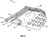
- Figure 1 shows a composite surface structure 200, 300 for the leading edge of an aircraft.
- the composite surface structure 200, 300 is a segment of an aircraft engine nacelle inlet lip.
- the surface structure 200, 300 includes a composite ice protection heater portion 10, 100.
- the composite heater portion 10, 100 is integrally incorporated into the composite surface structure 200, 300.
- the heater portion 10, 100 may include a plurality of spaced electrical heater elements 18A-18F. The heater elements 18A-18F may be collectively or individually energized to prevent and/or eliminate ice formation on the leading edge of the structure 200, 300 during service.
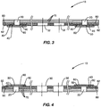
- Fig. 2 shows one embodiment of a moldable composite electrothermal heating apparatus 10, 100.
- the generally thin and generally flexible heater apparatus 10, 100 forms a moldable sheet capable of conforming to at least a portion of a surface contour of an external surface of an aircraft.
- the composite heater apparatus 10, 100 can be constructed such that the heater 10, 100 is substantially flat in an unrestrained state.
- the heater apparatus 10, 100 can be constructed such that the heater 10, 100 has a desired three-dimensional, non-flat shape in an unrestrained state (like that shown in Figure 2 , for example).
- the composite heater apparatus 10, 100 is capable of conforming to an underlying aircraft support surface or structure, such as an inlet lip of an aircraft engine nacelle.
- the composite heater apparatus 10, 100 can include a plurality of spaced openings 30 that extend through the entire thickness of the heater.
- the composite heater 10, 100 may also include at least some openings 32 that extend only partially through the thickness of the heater 10, 100.
- the spaced openings 30, 32 can serve two functions. First, the spaced openings 30, 32 may provide each heater element 18A-18F with a desired degree of electrical resistance, such that when energized, each heater element imparts a desired level of resistance heating to an associated surface of an aircraft.
- the spaced openings 30, 32 may act to attenuate at least some aircraft noise by absorbing or dissipating at least some acoustic energy at or near the surface of the heater 10.
- the spaced openings 30, 32 may have any desired size or shape, and may be arranged in any desired array or pattern in the composite heater apparatus 10, 100.
- the openings 30, 32 may be spaced over substantially the entire extent of the heater 10, 100, or may be provided in only select portions of the heater apparatus 10, 100.
- the heater apparatus 10, 100 includes six span-wise heating elements 18A-18F (indicated by dashed lines).
- the full openings 30 are spaced over substantially all of heating elements 18A-18D, and the partial openings 32 are provided in heating elements 18E and 18F.
- the full openings 30 can be provided in those heater elements 18 that are located in surface regions of the heater structure 10, 100 where at least some noise attenuation is desired.
- partial openings 32 can be provided in those heater elements that are located in surface regions where noise attenuation is either unnecessary or less desirable.
- the openings 30, 32 are holes that are about 0.1 inch (0.3 cm) in diameter, and are substantially equally spaced on about 0.15 inch (0.38 cm) centers. Accordingly, in this embodiment, the openings 30, 32 consume slightly less than about 30 percent of the total surface area of the heater assembly 10, 100. In other words, the openings 30, 32 define a percent of open area (POA) of nearly 30 percent. Smaller or larger hole diameters and center spacings, as well as percentages of POA also may be used, as desired.
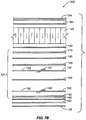
- Figures 3-5 show enlarged details of one representative laminated composite construction of a heater apparatus 10 like that shown in Fig. 2 .
- the heater apparatus 10 includes at least one outermost electrically insulating layer 60 covering at least one underlying electrically conductive layer 50.
- the outermost insulating layer 60 may include one or more plies of low dielectric glass cloth that are pre-impregnated with a suitable curable resin.
- Suitable resins include, but are not limited to, epoxy resins, cynate esters, phenolic resins, bismaleimide (BMI) resins, polyimide resins, and the like.
- the type of curable resin used may be based upon the maximum anticipated service temperature of the heater apparatus 10.
- phenolic resins may be used for maximum service temperatures up to about 225°F. (107°C), cynate esters for temperatures up to about 250°F. (120°C), epoxy resins for temperatures up to about 300°F. (150°C), BMI resins for temperatures up to about 400°F. (200°C), and polyimide resins for temperatures up to about 550-650°F. (290-340°C).
- the insulating layer 60 may include one or more plies of Style 120 pre-impregnated woven E-glass fabric of a type that is well known in the art.
- the insulating layer 60 may include one or more plies of Style 7781 E-glass woven fabric prepreg, of a type that is well known in the art.
- the electrically insulating layer 60 may be constructed of any other suitable electrically insulating material. Suitable electrically insulating layers 60 preferably have a dielectric constant less than or equal to about 7, and a dielectric tangent less than or equal to about 12x10 4 at a frequency of about 1 MHz at room temperature.
- the electrically conductive layer 50 is a sheet that includes a carbon-based material such as graphite fibers.
- the sheet 50 may be a single layer of an electrically conductive woven or unidirectional graphite fabric or tape impregnated with a suitable curable resin.
- suitable resins include, but are not limited to, epoxy resins, cynate esters, phenolic resins, bismaleimide (BMI) resins, polyimide resins, and the like. The type of resin used may be selected based upon the maximum anticipated service temperature of the heater 10, as described above regarding the insulating layers 60.
- the electrically conductive layer 50 may include plural layers of electrically conductive woven and/or unidirectional graphite fabrics or tapes.
- the electrically conductive layer 50 may be any substantially continuous conductive material that is capable of conducting an electric current when subjected to an electric potential, and that is capable of receiving a plurality of spaced openings therethrough without adversely affecting the material's ability to conduct an electric current.
- Other materials with these characteristics are known to persons skilled in the art.
- At least one first electrically conductive bus strip 40 is positioned in electrical contact with at least a portion of the electrically conductive sheet 50 proximate to one edge of the sheet 50.
- at least one second electrically conductive bus strip 40 is in electrical contact with an opposed portion of the electrically conductive sheet 50 proximate to an opposed edge of the sheet 50.
- the first and second bus strips 40 preferably are placed in electrical contact with opposed edges that correspond to opposed ends of the unidirectional threads.
- the bus strips 40 extend along substantially the full length of the respective opposed edges of the conductive sheet 50.
- the opposed bus strips 40 permit an electric potential to be substantially uniformly established across the electrically conductive sheet 50 by connecting the bus strips 40, 42 to a suitable power source.
- the bus strips 40 are highly conductive metal strips, such as thin strips of copper or the like.
- at least one second electrically insulating layer 62 underlies the conductive sheet layer 50 and the bus strips 40.
- the second insulating layer 62 may be a layer of pre-impregnated low-dielectric glass fabric such as a single ply of Style 120 or Style 7781 E-glass/epoxy fabric, or any other suitable electrically insulating material. Accordingly, the conductive sheet 50 and bus strips 40 are encapsulated between the insulating layers 60, 62. As shown in Figures 3-6A , and in order to minimize the possibility of delamination during service, strips of adhesive material 82 may be disposed between the bus strips 40 and the second insulating layer 62. The strips of adhesive material 82 enhance bonding between the bus strips 40 and the insulating layer 62 after curing.
- the strips of adhesive material 82 may be strips of FM-300 epoxy adhesive film, available from Cytec Industries, Inc.
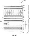
- the combination of the insulating layers 60, 62, conductive layer 50, bus strips 40, and adhesive strips 82 are collectively referred to as the heater element layers 14 (as shown in Figs. 6A , 7A and 8 ).
- the electrically conductive layer 50 may include a plurality of spaced conductive sheets 50.
- Each of the spaced conductive sheets 50 may form one of a plurality of separate heating elements, such as heating elements 18A-18F as shown in Figs. 1 and 2 .
- adjacent edges of adjacent conductive sheets 50 are sufficiently spaced apart to prevent electrical current from passing between adjacent conductive sheets 50 during service.
- inter-heater insulating strips 65 may be positioned between adjacent edges of adjacent conductive sheets 50 to electrically isolate adjacent conductive sheets 50 from each other. As shown in Fig.
- each inter-heater insulating strip 65 may extend beneath an edge of a first conductive sheet 50, and an opposed second edge of each insulating strip 65 may extend over an adjacent edge of an adjacent conductive sheet 50.
- the inter-heater insulating strips 65 preferably are strips of low dielectric glass prepreg fabric, such as Style 120 or Style 7781 fabric. Alternatively, other electrically insulating materials may be used for the insulating strips 65.
- the composite heater apparatus 10 may further include one or more structural layers 70 beneath the heating element layers 14.
- the structural layers 70 support and reinforce the heating element layers 14, and help to maintain the heater apparatus 10 in a desired contour or shape.
- the structural layers 70 may be a plurality of stacked pre-impregnated glass/epoxy fabric layers, for example.
- the structural layers 70 may be adhered to the heating element layers 14 by a suitable layer or film of adhesive material 80.
- One suitable low-flow adhesive that may be used to form the adhesive layer 80 is a nitrile phenolic adhesive available from 3M Co., for example.
- the structural layers 70 may be adhered to the heating element layers 14 by bonding together pre-impregnated resins within the insulating layer 62 and within at least one of the structural layers 70 during an elevated-temperature curing cycle.
- the heater apparatus 10 further includes a plurality of spaced openings 30 that extend through the first insulating layer 60, the conductive sheet layer 50, the second insulating layer 62, and the structural layers 70.
- openings also can be provided through the bus strips 40, the bus strips 40 preferably are non-perforated.
- the openings 30 may provide the conductive layer 50 with a desired degree of electrical resistance, such that when an electrical potential is established across the opposed bus strips 40, a desired degree of thermal energy is emitted from the conductive sheet 50.
- the openings 30 can provide the heater apparatus 10 and an aircraft surface structure 200 incorporating the heating device 10 with desirable noise attenuation characteristics.
- one or more attachment openings 20 may be provided to permit electrical connection of the bus strips 40 to a power source in a conventional fashion.
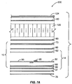
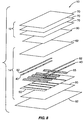
- a method of producing the heater apparatus 10 described above includes assembling the layers of the composite heater structure 10 as shown in Fig. 8 , for example.
- the composite layup and curing steps and processes generally described herein are well known in the art.
- the first insulating layer 60 can be laid over a layer of suitable peel ply material 92.
- the peel ply material 92 may be Code 60001 Peel Ply by Richmond Aircraft Products, Inc., for example.
- At least one sheet of conductive material 50 can be laid on the first insulating layer 60.
- the first insulating layer 60 is oversized, such that excess material extends beyond the outer edges of the conductive sheets 50.
- the sheets 50 should be sized and spaced such that adjacent conductive sheets 50 do not contact each other.
- pairs of opposed bus strips 40 can be placed along edges of the conductive sheets 50 as shown in Fig. 8 .
- the bus strips 40 are sized such that they extend along substantially the full lengths of the opposed edges of their respective conductive sheets 50.
- four separate bus strips 40 may arranged such that one bus strip forms a common ground on a first edge of a conductive sheet 50, and the other three "hot" bus strips 40 are spaced along an opposed second edge of the conductive sheet 50.
- the bus strips 40 may be overlaid with adhesive strips 82 to enhance bonding with adjacent layers.
- a second insulating layer 62 can be laid over the conductive sheets 50, bus strips 40, and adhesive strips 82, thus completing lay-up of the heater element layers 14.
- a release layer 90 can be laid over the second insulating layer 62.
- the release layer 90 may be a layer of porous ArmalonTM by Du Pont, for example.
- structural layers 12 comprising one or more reinforcement layers 70 can be laid over the heating element layers 14 and the release layer 90.
- the stacked layers 12, 14 then can be prepared for curing at an elevated temperature using methods known in the art.
- the stacked layers 12, 24 are placed inside a vacuum bag to extract entrapped air from the lamination. Once the air has been excluded, pressure is applied to compress the stack, and the stack is subjected to elevated temperatures to cause the pre-impregnated epoxy resins to meld and cure.
- the heater apparatus 10 may be generally flat in shape, or may have a desired three-dimensional contoured shape like that shown in Fig. 2 .
- the stacked layers may be compressed between substantially flat platens during curing, for example.
- the stack may be laid up and pressed within a suitably shaped mold to impart the desired three-dimensional shape to the lamination during curing.
- the cured composite can be removed from the mold and vacuum bag, and prepared for perforating.
- sheets of perforated maskant 94 can be selectively placed over those portions of the stacked layers that are to be perforated, as shown in Fig. 10 .
- Non-perforated sheets of maskant 96 and non-perforated strips of maskant 98 can be applied to those portions of the stacked layers that do not receive openings.
- the maskant sheets 94, 96 and maskant strips 98 may be a vinyl masking material available from Diamond Manufacturing, Co., or any other suitable masking material.
- the masked surface is blasted with conventional techniques using an erosive media such as metal or ceramic particles, or another suitable erosive media.
- the erosive blasting is continued until the openings 30 extend through the full thickness of the stack at all exposed, non-masked locations.
- erosive blasting is a preferred method of forming the openings 30 in the stacked layers, other suitable perforation processes also may be used.
- the openings 30 may be formed by mechanical drilling, laser drilling, electron beam drilling, chemical etching, or the like.
- the maskant 94, 96, 98 is removed, and the edges of the stacked layers can be trimmed to remove any excess material.
- a release layer 90 is included between the heater element layers 14 and the support layers 12, the release layer 90 is removed.
- Those portions of the heater element layers 14 protected by the non-perforated maskant 96 remain non-perforated after erosive blasting.
- a non-perforated region of the heater element layers 14 may be separately masked with a perforated maskant and blasted with an erosive material to perforate that region only with partial openings 32. In this way, at least some portions of the heater element layers 14 may include partial openings 32 that have no corresponding openings in matching portions of underlying support layers 12.
- partial openings 32 may be desirable to modify the electrical resistivity of the conductive heating layer 50, without affecting the noise attenuation aspects of the heater. As shown in Figure 2 , such partial openings 32 may be provided in portions of a composite heater 10 where electrical resistance modification is required, but sound attenuation is less important or not required. For example, in the heater apparatus 10 shown in Fig. 2 for use in the nacelle noselip segment 200 shown in Fig. 1 , partial openings 32 may be provided in outermost heater elements 18E and 18F, since these outermost heater elements correspond to portions of the nacelle inlet lip that are relatively distant from the noise-generating turbine blades of an associated aircraft engine.
- a layer of adhesive material 80 can be applied between the heater element layers 14 and the support layers 12 in such a manner that the adhesive material 80 does not substantially block the full openings 30.
- Corresponding openings 30 in the heating element layers 14 and support layers 12 are re-aligned with each other when the two sets of layers 12, 14 are bonded together by the adhesive 80.
- the layers 12, 14 are again placed in a suitable vacuum bag, and the adhesive 80 is cured at an elevated temperature to form a unitary heater structure 10. After the adhesive 80 is cured, the heater device 10 is finally trimmed of any remaining excess material.
- the heater device 10 can be finally trimmed after the assembly has been perforated, thereby completing the heater device 10.
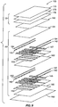
- the heater apparatus 100 includes plural layers of electrically conductive sheets 150, 152 separated by one or more electrically insulating layers 160, 162. Though only two layers of conductive sheet layers 150, 152 are shown in Figs. 6B , 7B and 9 , the heater device 100 may include two or more layers of conductive sheets 150, 152, each separated by one or more insulating layers 160, 162 as desired. The overlapping conductive sheet layers 150, 152 may form redundant heating elements to provide backup heaters in the event one or more of the heating elements formed by one of the conductive sheets 150, 152 becomes inoperative.
- the heating elements formed by overlapping conductive sheet layers 150, 152 may be selectively energized in any desired combination to generate a desired level of heating from a particular region of the device 100.
- the overlapping conductive heater layers 150, 152 may be identically sized and positioned within the heater structure 10 as shown in Figure 9 , or may have different sizes and positions in the structure 10.
- the heater apparatus 100 otherwise may be substantially similar to the heater apparatus 10 having a single conductive layer 50 as described above.
- electrically conductive bus strips 140, 142 are placed in contact with opposed portions of the conductive layers 150, 152 and permit an electrical voltage to be induced across the conductive heater layers 150, 152.
- inter-heater insulating strips 165, 167 may be provided between adjacent edges of adjacent conductive sheets 150, 152 to minimize the possibility of an electric current passing between adjacent conductive sheets 150, 152 when the sheets are energized.
- strips of adhesive material 182, 184 may be disposed between the bus strips 140, 142 and the adjacent insulating layers 162, 164.
- the strips of adhesive material 182, 184 enhance bonding between the bus strips 40 and the insulating layer 62 during curing.
- the combination of the insulating layers 160, 162, and 164, conductive sheet layers 150, 152, bus strips 140, 142, and adhesive strips 182, 184 are collectively referred to as the heater element layers 16 (as shown in Fig. 9 ).
- the composite heater assembly 100 includes a plurality of spaced full openings 30 therethrough like those described above for heater apparatus 10.
- the composite heater assembly 100 also may include a plurality of spaced partial openings 32 like those described above for heater apparatus 10.
- one or more attachment openings 20 may be provided in composite heater assembly 100 to permit electrical connection of the bus strips 140, 142 to a power source.
- a method of producing the multi-layer heater apparatus 100 described above includes assembling the layers of the composite heater structure 100 as shown in Fig. 9 .
- a first insulating layer 160 can be laid over a layer of peel ply material 192.
- At least one sheet of conductive material 150 can be laid over the first insulating layer 160.
- the first insulating layer 160 can be sized such that excess material extends beyond the outer edges of the conductive sheets 150.
- the heater apparatus 100 includes plural conductive sheets 150 forming separate heater elements, the sheets 150 can be sized and spaced such that the conductive sheets 150 do not contact each other.
- inter-heater insulating strips 165 can be placed between adjacent conductive sheets 150 as shown in Figure 7B .
- the inter-heater insulation strips 165 may be strips of pre-impregnated dielectric glass fabric, or any other suitable electrically insulating material. Pairs of opposed bus strips 140 can be placed along opposed edges of the conductive sheets 150 as shown in Fig. 9 , for example. Preferably, the bus strips 140 are sized such that they extend along substantially the full lengths of the opposed edges of their respective conductive sheets 150. In order to enhance the bond between the bus strips 140 and an overlaid adjacent layer 162, adhesive strips 182, 184 may be placed over the bus strips 140, 142 as shown in Figs. 6B and 9 . Next, a second electrically insulating layer 162 can be laid over the layers of conductive sheets 150, bus strips 140, and adhesive strips 182.
- the lay-up process is continued by adding one or more additional insulating layers 162, one or more additional layers of conductive sheet layers 152, one or additional layers of inter-heater insulating strips 167, one or more additional layers of bus strips 142, one or additional layers of adhesive strips 184, one or more additional insulating layers 164, and so on.
- a release layer 190 and one or more structural support layers 170 can be laid over the final insulating layer 164.
- the stacked layers are placed inside a vacuum bag, and compressed and cured at an elevated temperature in the manner described above.
- the composite structure is masked and perforated as described above regarding the single-layer heating device 10.
- the release layer 190 is removed from the lamination, and the separate portions of the structure are adhered together by a suitable adhesive 180 as described above.
- the release layer 190 may be omitted during lay-up, thereby eliminating the need for adhesive.
- the heater assembly 100 is finally trimmed to remove excess material.
- the multi-layer heater assembly 100 may be formed in a substantially flat state, or may be laid up and cured in a suitable mold to impart a desired three-dimensional shape to the heater device 100.
- the heater device 100 may be molded to have a curved shape that conforms to a nacelle inlet lip, as shown in Fig. 2 .
- a heater apparatus 10, 100 may be incorporated into a surface structure of an aircraft to provide ice protection, or to provide noise attenuation in addition to ice protection.
- the heater device 10, 100 can be embedded in an aircraft engine nacelle inlet noselip segment, as shown in Fig. 1 .
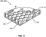
- the heater device 10, 100 is mounted over an open-cell matrix 120 with a suitable adhesive 80, 180 as shown in Figs. 6A-7B and 11 .
- the open-cell matrix 120 may be an open-cell honeycomb structure, any other suitable open-cell structure, or any combination thereof.
- the open-cell matrix layer 120 may include a layer of HexWeb(R) HRP Flex-Core(R) available from Hexcel Corporation.
- One or more non-perforated layers 124 may be attached on the rear surface of the open-cell matrix 120 by a suitable adhesive or adhesive layer 80, 180.
- the full openings 30 in the heater assembly 10, 100 provide passageways between the exterior of the heater device 10, 100 and the cells 122 of the open-cell matrix 120.
- Such a construction can provide substantial absorption of acoustic energy by creating Helmholtz resonance. Accordingly, such a structure 200, 300 is particularly suited for use on a nacelle inlet lip to attenuate engine fan noise, and to provide ice protection at the nacelle inlet.
- the bus strips 40, 140, 142 of the heater 10, 100 are connected to a suitable power source, and operation of each resistance heating element 50, 150, 152 or combination of heating elements 50, 150, 152 is controlled by a suitable control device as is known in the art.
- Heat dissipated from the conductive layers 50, 150, 152 of the composite heater 10, 100 can effectively minimize ice accumulation on the associated surface of the aircraft, or can melt or cause the delamination of ice that accumulates on the aircraft surface.
- the outermost surface of an aircraft surface structure that incorporates a composite heater 10, 100 may include a durable, acoustically permeable erosion layer 35, 135.
- the erosion layer 35, 135 is a micro-perforated titanium foil.
- the erosion layer 35, 135 may be a .008-inch (0.2 mm) thick titanium alloy foil having a plurality of spaced openings that are about 0.01 inch (0.3 mm) in diameter, and are spaced apart by about 0.02 inch (0.5 mm).
- the erosion shield 35, 135 shields the composite structure 200, 300 from erosion and damage during service, and provides a substantially smooth aerodynamic outer surface to the structure.
- the micro-perforations in the erosion layer 35, 135 permit at least some sound waves to pass through the outer surface structure 200, 300, travel through the openings 30 in the underlying composite heater 10, 100, and to enter the open cells 122 of the open-cell layer 120.
- the erosion shield may include a perforated portion or portions that coincide with an acoustically treated section or sections of the aircraft surface structure, and a non-perforated portion or portions that coincide with a non-acoustically treated section or sections of the structure.
- a layer of non-woven scrim cloth 37, 137 may be sandwiched between the composite heater 10, 100 and the erosion layer 35, 135 as shown in Figs. 6A-7B to further enhance the noise attenuation properties of the structure 200, 300.
- the conductive layers forming the resistance heating elements 50, 150, 152 may be constructed of a woven or unidirectional pre-impregnated fabric or tape including threads containing electrically conductive graphite fibers or another suitable conductive component.
- the electrical resistance of a sheet of electrically conductive fabric 450 can be increased by introducing a plurality of spaced openings 430 through the fabric 450.
- the spaced openings 430 create discontinuities in at least some of the woven threads, thereby interrupting the flow of electrical current through the affected threads when a voltage is applied between the bus strips 440. This interruption of current flow forces an electrical current to seek a more circuitous, less direct conductive path between the bus strips 440, thereby generating resistance heating in the conductive fabric 450.
- Spaced, open perforations 430 are desirable when a composite heater 10, 100 is incorporated into a composite aircraft surface structure 200, 300 like that shown in Fig. 1 that attenuates aircraft noise.
- Other types of discontinuities in an electrically conductive woven composite fabric also may be used to provide a desired rate of resistance heating from the fabric.
- a plurality of spaced slits 530 may be provided in a woven conductive sheet 550. Like the spaced perforations 430 discussed above, the slits 530 increase the effective electrical resistance to current flow between opposed bus strips 540 when an electric potential is applied between the bus strips 540. As shown Fig.
- the spacing of slits 530 in woven fabric 550 can be varied to provide varying local electrical resistances across the extent of the woven fabric 550.
- parallel slits 530 may be closely grouped together in a local region 532 to create an area of relatively high electrical resistivity.
- This region 532 forms a "hot spot" where the rate of dissipated resistance heating is greater than other areas of the fabric having more widely spaced slits 530.
- Such a "hot spot" 532 may be desirable along a forward-most portion of a leading edge of an aircraft surface structure, for example, which is susceptible to ice accumulation. Accordingly, the unevenly spaced slits 530 create at least one locally discontinuous property in the weave pattern.
- a composite heater structure may include a fabric having a plurality of conductive threads, but without openings such as holes, perforations, slits, or other such discontinuities.
- a composite heater structure 600 can include a woven fabric 650 wherein the conductive threads 652 essentially extend in a single direction.
- the balance of threads forming the woven fabric structure 650 are non-conductive threads, such as low dielectric glass threads, for example.
- conductive threads 652 extend in a warp direction between two opposed bus strips 640.
- the parallel conductive threads 652 may be equally spaced, or the thread spacing may be closer in one or more regions 632 of the fabric 650 to create different effective local electrical resistances in different portions of the fabric 650.
- the effective electrical resistance in that portion 632 of the woven fabric 650 having more closely spaced conductive threads 652 is less than the local electrical resistance in that portion of the fabric 650 having more widely spaced conductive threads 652. Accordingly, when an electrical voltage is applied across opposed bus strips 640, the resistance heating generated from region 632 is less than the heating produced where the conductive threads 632 are more widely spaced. Accordingly, the arrangement of the conductive threads 632 creates at least one locally discontinuous property in the weave pattern.
- a composite heater apparatus 700 is shown in Fig. 15 .
- the heater 700 includes a sheet of woven fabric 750 including a first plurality of conductive threads 752 extending in a warp direction, for example, and a second plurality of conductive threads 754 extending in a fill direction.
- the spacing (threads per inch) of warp conductive threads 752 in the weave pattern is greater than the spacing (threads per inch) of conductive threads 754 extending in the fill direction.
- the balance of the weave pattern of the woven fabric 750 includes non-conductive threads, such as glass threads, for example.
- the fabric 750 includes fewer possible conductive paths for current than a composite fabric sheet woven entirely of conductive warp and fill threads 752, 754, the effective electrical resistance of the woven fabric sheet 750 is greater than the resistance of a composite fabric sheet woven entirely of conductive threads 752, 754. Accordingly, when an electric voltage is applied across the opposed bus strips 740, a greater amount of heat is dissipated from the woven sheet 750 than would result if the woven sheet was constructed entirely of conductive threads 752, 754.
- a person of ordinary skill in the art will recognize that certain modifications can be made to the described embodiments without departing from the scope of the invention as defined by the claims.
- a heater according to the invention also can be used on other portions of an aircraft where ice protection and/or a perforated or composite heater construction provide beneficial results, such as a wing or other control surface of an aircraft.
- a composite ice protection heater according to the invention may be used in combination with any structure or surface that requires heating, such as an aircraft floor panel, or the like.
- a composite ice protection heater according the invention may include at least some openings that extend through the entire thickness of the heater, may include at least some openings that extend only partially through the thickness of the heater, or both.
- a composite ice protection heater according to the invention may include a non-woven unidirectional composite fabric or tape including at least some electrically conductive threads, and no openings.
- the composite construction of each of the variously described embodiments of the invention may include additional layers or elements not specifically described or shown herein.
Claims (2)
- Chauffage de protection contre givrage (700) pour un composant d'avion comprenant :une feuille de toile tissée (750) comprenant une pluralité de fils de chaîne et de remplissage agencés selon un motif de tissage, dans lequel au moins une partie des fils de chaîne (752) et au moins une partie des fils de remplissage (754) sont électroconducteurs et espacés les uns des autres ; etdeux bandes omnibus opposées (740) ;dans lequel l'espacement des fils conducteurs de chaîne (752) selon le motif de tissage est supérieur à l'espacement des fils conducteurs de remplissage (754) ; etdans lequel le reste du motif de tissage de la toile tissée (750) comporte des fils non conducteurs et les fils conducteurs s'étendent dans une direction de chaîne entre les deux bandes omnibus opposées (740) ; caractérisé en ce que les deux bandes omnibus opposées (740) sont des bandes métalliques conductrices qui s'étendent sensiblement dans le sens de la longueur totale des bords opposés respectifs de la feuille de toile tissée (750).
- Chauffage de protection contre givrage selon la revendication 1, dans lequel le motif de tissage comporte une pluralité de fils sensiblement non conducteurs entrelacés avec les fils conducteurs (752, 754).
Applications Claiming Priority (3)
| Application Number | Priority Date | Filing Date | Title |
|---|---|---|---|
| US11/276,344 US7291815B2 (en) | 2006-02-24 | 2006-02-24 | Composite ice protection heater and method of producing same |
| EP11000623.6A EP2330034B1 (fr) | 2006-02-24 | 2007-02-23 | Chauffage de protection contre givrage pour un composant d'un aéronef |
| EP07003782A EP1826119B1 (fr) | 2006-02-24 | 2007-02-23 | Chauffage de protection composite contre le givre et son procédé de production |
Related Parent Applications (3)
| Application Number | Title | Priority Date | Filing Date |
|---|---|---|---|
| EP11000623.6A Division EP2330034B1 (fr) | 2006-02-24 | 2007-02-23 | Chauffage de protection contre givrage pour un composant d'un aéronef |
| EP11000623.6A Division-Into EP2330034B1 (fr) | 2006-02-24 | 2007-02-23 | Chauffage de protection contre givrage pour un composant d'un aéronef |
| EP07003782A Division EP1826119B1 (fr) | 2006-02-24 | 2007-02-23 | Chauffage de protection composite contre le givre et son procédé de production |
Publications (2)
| Publication Number | Publication Date |
|---|---|
| EP2873618A1 EP2873618A1 (fr) | 2015-05-20 |
| EP2873618B1 true EP2873618B1 (fr) | 2020-04-22 |
Family
ID=38117208
Family Applications (3)
| Application Number | Title | Priority Date | Filing Date |
|---|---|---|---|
| EP11000623.6A Active EP2330034B1 (fr) | 2006-02-24 | 2007-02-23 | Chauffage de protection contre givrage pour un composant d'un aéronef |
| EP07003782A Active EP1826119B1 (fr) | 2006-02-24 | 2007-02-23 | Chauffage de protection composite contre le givre et son procédé de production |
| EP14198096.1A Active EP2873618B1 (fr) | 2006-02-24 | 2007-02-23 | Chauffage de protection contre givrage pour un composant d'avion |
Family Applications Before (2)
| Application Number | Title | Priority Date | Filing Date |
|---|---|---|---|
| EP11000623.6A Active EP2330034B1 (fr) | 2006-02-24 | 2007-02-23 | Chauffage de protection contre givrage pour un composant d'un aéronef |
| EP07003782A Active EP1826119B1 (fr) | 2006-02-24 | 2007-02-23 | Chauffage de protection composite contre le givre et son procédé de production |
Country Status (2)
| Country | Link |
|---|---|
| US (1) | US7291815B2 (fr) |
| EP (3) | EP2330034B1 (fr) |
Families Citing this family (103)
| Publication number | Priority date | Publication date | Assignee | Title |
|---|---|---|---|---|
| US7763833B2 (en) * | 2004-03-12 | 2010-07-27 | Goodrich Corp. | Foil heating element for an electrothermal deicer |
| US7923668B2 (en) * | 2006-02-24 | 2011-04-12 | Rohr, Inc. | Acoustic nacelle inlet lip having composite construction and an integral electric ice protection heater disposed therein |
| FR2898868B1 (fr) * | 2006-03-24 | 2008-12-12 | Aircelle Sa | Structure pour levre d'entree d'air de nacelle a degivrage electrique |
| US8405561B2 (en) * | 2007-02-01 | 2013-03-26 | Si2 Technologies, Inc. | Arbitrarily-shaped multifunctional structures and method of making |
| US9581033B2 (en) * | 2007-02-06 | 2017-02-28 | United Technologies Corp0Ration | Surface mounted flexible heater for gas turbine engine application |
| EP2155470B1 (fr) * | 2007-05-31 | 2011-01-12 | Airbus Operations GmbH | Procédé de production d'un revêtement composite dans le domaine aéronautique et astronautique |
| US20090020521A1 (en) * | 2007-07-18 | 2009-01-22 | Thomas Blaszczykiewicz | Heating Pad System For Orthopedic Braces And The Like |
| GB0721547D0 (en) * | 2007-11-01 | 2007-12-12 | Heat Trace Ltd | Self-regulating electrical heating cable |
| US7837150B2 (en) * | 2007-12-21 | 2010-11-23 | Rohr, Inc. | Ice protection system for a multi-segment aircraft component |
| US8049147B2 (en) | 2008-03-28 | 2011-11-01 | United Technologies Corporation | Engine inlet ice protection system with power control by zone |
| US8006934B2 (en) * | 2008-03-31 | 2011-08-30 | United Technologies Corporation | Heating architecture for a composite fairing |
| US20090260341A1 (en) * | 2008-04-16 | 2009-10-22 | United Technologies Corporation | Distributed zoning for engine inlet ice protection |
| CN102301122B (zh) * | 2008-07-30 | 2014-05-14 | 埃尔塞乐公司 | 用于飞行器发动机机舱的声衰减板 |
| FR2935357B1 (fr) * | 2008-09-03 | 2010-08-27 | Aircelle Sa | Procede de fabrication d'un element de nacelle |
| FR2935356B1 (fr) | 2008-09-03 | 2010-08-27 | Aircelle Sa | Procede de fabrication d'un panneau acoustique d'une levre d'entree d'air d'une nacelle |
| EP2202151B1 (fr) * | 2008-11-17 | 2016-09-14 | Goodrich Corporation | Aéronef avec un système de protection contre le givre |
| US9004407B2 (en) | 2008-12-24 | 2015-04-14 | Middle River Aircraft Systems | Anti-icing system and method for preventing ice accumulation |
| FR2941439B1 (fr) * | 2009-01-28 | 2011-01-14 | Aircelle Sa | Dispositif de degivrage electrique et systeme de controle associe |
| FR2942616B1 (fr) * | 2009-03-02 | 2011-03-11 | Aerazur | Procede d'assemblage d'un tapis degivreur sur une piece de voilure |
| FR2943038B1 (fr) * | 2009-03-13 | 2012-07-27 | Aircelle Sa | Dispositif de degivrage,notamment pour nacelle d'aeronef |
| US20120186433A1 (en) * | 2009-04-06 | 2012-07-26 | Scapa North America | Protective shield material |
| DE102009052535C5 (de) * | 2009-11-11 | 2023-06-01 | Nbhx Trim Gmbh | Innenraumverkleidung |
| BR112012017396A2 (pt) * | 2010-01-14 | 2016-04-19 | Saab Ab | sistema multifuncional de descongelamento / anticongelamento |
| BR112012017304A2 (pt) * | 2010-01-14 | 2016-04-19 | Saab Ab | artigo com função de degelo/antigelo |
| US8446330B1 (en) * | 2010-01-26 | 2013-05-21 | The Boeing Company | Antenna fabrication |
| US20110233340A1 (en) * | 2010-03-29 | 2011-09-29 | Christy Daniel P | Aircraft ice protection system |
| US10293947B2 (en) | 2010-05-27 | 2019-05-21 | Goodrich Corporation | Aircraft heating system |
| US8927910B2 (en) * | 2011-04-29 | 2015-01-06 | Board Of Regents Of The Nevada System Of Higher Education, On Behalf Of The University Of Nevada, Reno | High power-density plane-surface heating element |
| JP5436491B2 (ja) * | 2011-05-20 | 2014-03-05 | 北陸エステアール協同組合 | 面状発熱体 |
| DE102011119844A1 (de) | 2011-05-26 | 2012-12-13 | Eads Deutschland Gmbh | Verbundstruktur mit Eisschutzvorrichtung sowie Herstellverfahren |
| FI20115536L (fi) * | 2011-05-31 | 2013-03-25 | Teknologian Tutkimuskeskus Vtt Oy | Tuuliturbiinin siipi ja tähän liittyvä valmistusmenetelmä |
| DE102011109696A1 (de) * | 2011-08-06 | 2013-02-07 | Daimler Ag | Funktionalisiertes Innenraumverkleidungsbauteil und Verfahren zu dessen Herstellung sowie Kraftfahrzeug mit dem Innenraumverkleidungsbauteil |
| US9221544B2 (en) | 2011-09-20 | 2015-12-29 | The Boeing Company | Integrated surface thermal management system |
| US9067679B2 (en) | 2011-12-30 | 2015-06-30 | Aerospace Filtration Systems, Inc. | Heated screen for air intake of aircraft engines |
| US10201039B2 (en) * | 2012-01-20 | 2019-02-05 | Gentherm Gmbh | Felt heater and method of making |
| BE1020543A3 (fr) * | 2012-02-24 | 2013-12-03 | Sonaca Sa | Procede de fabrication d'une peau de bord d'attaque par cuisson d'un empilement integrant des elements chauffants et des couches de fibres preimpregnees. |
| CA2867892A1 (fr) * | 2012-03-23 | 2013-09-26 | Soleno Textiles Techniques Inc. | Systeme panneau de chauffage faconnable |
| US9193466B2 (en) * | 2012-07-13 | 2015-11-24 | Mra Systems, Inc. | Aircraft ice protection system and method |
| US20140014776A1 (en) * | 2012-07-13 | 2014-01-16 | Kelly Aerospace Thermal Systems Llc | System containing an electric heating element and method for installation and use thereof |
| US8919494B2 (en) * | 2012-07-31 | 2014-12-30 | Rohr, Inc. | Electric heater for integration into an aircraft acoustic panel |
| US9603196B2 (en) * | 2012-12-14 | 2017-03-21 | Tech Design Llc | Self-regulating semi-conductive flexible heating element |
| ITTO20121152A1 (it) | 2012-12-27 | 2014-06-28 | Alenia Aermacchi Spa | Gondola motore per un aeromobile, dotata di un sistema integrato di protezione antighiaccio ed assorbimento acustico. |
| US20140263277A1 (en) * | 2013-03-13 | 2014-09-18 | Shui-Po Lee | Heating plate |
| US9321536B2 (en) | 2013-03-15 | 2016-04-26 | Unmanned Aerospace Technologies Ltd. | Methods and system for deicing a surface |
| GB2513652A (en) * | 2013-05-03 | 2014-11-05 | Rolls Royce Plc | Vehicle composite structure |
| US9868536B2 (en) * | 2013-10-30 | 2018-01-16 | Goodrich Corporation | Electrical interconnects for ice protection systems |
| WO2015095019A1 (fr) * | 2013-12-17 | 2015-06-25 | E. I. Du Pont De Nemours And Company | Tissu non-tissé présentant une faible adhérence de la glace |
| WO2015199785A2 (fr) * | 2014-04-10 | 2015-12-30 | Metis Design Corporation | Ensembles multifonctionnels |
| US20160076450A1 (en) * | 2014-04-21 | 2016-03-17 | Bob Burkett | Solar Jet Turbofan Aircraft Engine |
| US9708072B2 (en) | 2014-04-30 | 2017-07-18 | The Boeing Company | Aircraft engine nacelle bulkheads and methods of assembling the same |
| US9604438B2 (en) | 2014-04-30 | 2017-03-28 | The Boeing Company | Methods and apparatus for noise attenuation in an engine nacelle |
| US9656761B2 (en) | 2014-04-30 | 2017-05-23 | The Boeing Company | Lipskin for a nacelle and methods of making the same |
| US9938852B2 (en) * | 2014-04-30 | 2018-04-10 | The Boeing Company | Noise attenuating lipskin assembly and methods of assembling the same |
| US9251778B2 (en) | 2014-06-06 | 2016-02-02 | Industrial Technology Research Institute | Metal foil with microcracks, method of manufacturing the same, and sound-absorbing structure having the same |
| FR3024124B1 (fr) * | 2014-07-22 | 2018-03-02 | Safran Nacelles | Procede de mise en place d’un systeme de degivrage sur un aeronef, comportant le depot de couches de materiaux a l’etat solide et/ou fluide |
| GB201416012D0 (en) * | 2014-09-10 | 2014-10-22 | Rolls Royce Plc | Electrical panel |
| GB2531808A (en) | 2014-11-03 | 2016-05-04 | Short Brothers Plc | Methods and precursors for manufacturing a perforated composite part |
| US10563578B2 (en) * | 2015-02-18 | 2020-02-18 | Mra Systems, Llc | Acoustic liners and method of shaping an inlet of an acoustic liner |
| EP3366080A1 (fr) | 2015-10-19 | 2018-08-29 | LaminaHeat Holding Ltd. | Éléments de chauffage stratifiés ayant une résistance personnalisée ou non uniforme et/ou des formes irrégulières et procédés de fabrication |
| GB2547049B (en) * | 2016-02-08 | 2019-12-25 | Gkn Aerospace Services Ltd | Integrated heater |
| DE102016107908A1 (de) * | 2016-04-28 | 2017-11-02 | Jenoptik Advanced Systems Gmbh | Heizvorrichtung und Verfahren zum Herstellen derselben |
| US10392810B1 (en) * | 2016-06-22 | 2019-08-27 | James Demirkan | Universal lightweight and portable deicing mat |
| WO2018001435A1 (fr) * | 2016-06-30 | 2018-01-04 | Vestas Wind Systems A/S | Barres omnibus dans un agencement d'empilage |
| US10708979B2 (en) | 2016-10-07 | 2020-07-07 | De-Ice Technologies | Heating a bulk medium |
| US20180160481A1 (en) * | 2016-12-02 | 2018-06-07 | Goodrich Corporation | Method to join nano technology carbon allotrope heaters |
| US11382181B2 (en) * | 2016-12-02 | 2022-07-05 | Goodrich Corporation | Method to create carbon nanotube heaters with varying resistance |
| US10264627B2 (en) | 2016-12-08 | 2019-04-16 | Goodrich Corporation | Adjusting CNT resistance using perforated CNT sheets |
| US10494107B2 (en) * | 2017-01-03 | 2019-12-03 | Goodrich Corporation | Additive manufacturing of conformal deicing and boundary layer control surface for aircraft |
| US10458275B2 (en) | 2017-01-06 | 2019-10-29 | Rohr, Inc. | Nacelle inner lip skin with heat transfer augmentation features |
| EP3577340B1 (fr) * | 2017-02-06 | 2022-06-22 | Kjell Lindskog | Procédé et agencement concernant le chauffage d'ailes dans des parcs éoliens |
| CN108691704B (zh) * | 2017-04-10 | 2019-10-18 | 清华大学 | 发动机进气口结冰检测系统及除冰系统 |
| US11242767B2 (en) * | 2017-05-01 | 2022-02-08 | General Electric Company | Additively manufactured component including an impingement structure |
| US10787267B2 (en) * | 2017-05-30 | 2020-09-29 | Bell Helicopter Textron Inc. | Electrical bus arrangement for ice protection systems |
| CN107084100B (zh) * | 2017-06-19 | 2023-04-18 | 东方电气风电股份有限公司 | 一种基于石墨烯加热膜的风电叶片加热融冰系统及该叶片的制作方法 |
| US20180370637A1 (en) * | 2017-06-22 | 2018-12-27 | Goodrich Corporation | Electrothermal ice protection systems with carbon additive loaded thermoplastic heating elements |
| US20190016466A1 (en) * | 2017-07-13 | 2019-01-17 | Goodrich Coporation | Redundant heating of surfaces of an aircraft skin for controlling ice accretion |
| US10960983B2 (en) * | 2017-09-01 | 2021-03-30 | Textron Innovations Inc. | Tailored rotor-blade ice-protection system |
| GB2566550B (en) | 2017-09-19 | 2022-07-13 | Gkn Aerospace Services Ltd | Electrothermal heater mat and method of manufacture thereof |
| US10785831B2 (en) * | 2017-10-20 | 2020-09-22 | Goodrich Corporation | Micro-perforations for CNT heaters |
| US20190118929A1 (en) * | 2017-10-24 | 2019-04-25 | Goodrich Corporation | Method for reinforcing a composite sandwich panel |
| US10435134B2 (en) * | 2017-12-12 | 2019-10-08 | The Boeing Company | Core structures for composite panels of an aircraft, composite panels and aircraft including the core structures, and methods of manufacturing the composite panels |
| JP7223386B2 (ja) | 2017-12-15 | 2023-02-16 | 国立研究開発法人宇宙航空研究開発機構 | ファンブレード及びエンジン |
| US10541065B2 (en) | 2017-12-21 | 2020-01-21 | The Boeing Company | Multilayer stack with enhanced conductivity and stability |
| CN110198574B (zh) * | 2018-02-27 | 2022-08-09 | 新疆金风科技股份有限公司 | 防雷电热融冰装置及其制造方法、叶片和风力发电机组 |
| EP3546364A1 (fr) * | 2018-03-28 | 2019-10-02 | Ratier-Figeac SAS | Appareil de dégivrage |
| GB2574184B (en) * | 2018-03-29 | 2020-12-02 | Gkn Aerospace Services Ltd | Ice removal system |
| US11136131B2 (en) * | 2018-07-11 | 2021-10-05 | Goodrich Corporation | Ice protection system for a component of an aerodynamic system |
| US11130559B2 (en) * | 2018-08-20 | 2021-09-28 | Goodrich Corporation | Heated panels with ballistic structures |
| CA3110343A1 (fr) * | 2018-08-27 | 2020-03-05 | De-Ice Technologies, Inc. | Systemes de degivrage |
| FR3085437B1 (fr) * | 2018-09-05 | 2020-11-20 | Airbus Operations Sas | Structure d’entree d’air d’une nacelle d’aeronef |
| US11002188B2 (en) | 2018-09-14 | 2021-05-11 | Rohr, Inc. | Nozzle for an aircraft propulsion system |
| CN114555940A (zh) * | 2019-08-05 | 2022-05-27 | 维斯塔斯风力系统集团公司 | 带有电热加热元件的风力涡轮机叶片 |
| CN110481795B (zh) * | 2019-09-11 | 2021-04-09 | 山东大学 | 一种石墨烯复合材料直升机旋翼防除冰装置及制作方法 |
| USD911038S1 (en) | 2019-10-11 | 2021-02-23 | Laminaheat Holding Ltd. | Heating element sheet having perforations |
| US11613373B2 (en) | 2020-03-13 | 2023-03-28 | Rohr, Inc. | Nozzle for a thermal anti-icing system |
| DE102020206087A1 (de) | 2020-05-14 | 2021-11-18 | Fraunhofer-Gesellschaft zur Förderung der angewandten Forschung eingetragener Verein | Selbst-desinfizierender Gegenstand |
| JP2021183832A (ja) * | 2020-05-22 | 2021-12-02 | 三菱重工業株式会社 | 風車翼、風車、及び、風車翼の製造方法 |
| US20230124999A1 (en) * | 2021-10-14 | 2023-04-20 | Goodrich Corporation | Aircraft heating system for thermally disadvantaged zones |
| FR3130755A1 (fr) * | 2021-12-20 | 2023-06-23 | Airbus Operations | Dispositif de chauffage à matelas chauffant pour un système de protection contre le givre d’un aéronef. |
| FR3123049A1 (fr) * | 2021-12-20 | 2022-11-25 | Airbus Operations | Système de protection électrique contre le givre d’une nacelle d’aéronef. |
| CN114524080B (zh) * | 2022-02-18 | 2024-04-09 | 中国航发北京航空材料研究院 | 碳纳米管膜电热防除冰的复合材料蒙皮结构及其制备方法 |
| CN116056269A (zh) * | 2023-03-14 | 2023-05-02 | 芜湖市安瑞电热带制造有限公司 | 一种管道电伴热用电热带 |
| CN116931507B (zh) * | 2023-09-18 | 2024-01-12 | 成都飞机工业(集团)有限责任公司 | 一种群孔穿孔控制方法、装置、存储介质及电子设备 |
Family Cites Families (64)
| Publication number | Priority date | Publication date | Assignee | Title |
|---|---|---|---|---|
| US2108041A (en) * | 1934-08-21 | 1938-02-15 | Paul Gayne | Aeroplane |
| US2496279A (en) * | 1945-02-10 | 1950-02-07 | Safeway Heat Elements Inc | Flexible electric heater for deicing airfoils |
| US2678993A (en) * | 1952-03-13 | 1954-05-18 | Boer Gerard W De | Woven resistance or heater device |
| GB885131A (en) * | 1958-04-24 | 1961-12-20 | Goodrich Co B F | Apparatus for and method of making a heating structure |
| GB926025A (en) * | 1960-11-18 | 1963-05-15 | Dowty Rotol Ltd | Electrical de-icing devices |
| US3349359A (en) * | 1964-12-18 | 1967-10-24 | Templeton Coal Company | Electrical heating elment |
| GB1386792A (en) | 1971-04-08 | 1975-03-12 | Rotax Ltd | Electrical heating apparatus for reducing or preventing the formation of ice on aircraft parts |
| US3935422A (en) * | 1974-02-12 | 1976-01-27 | Burlington Industries, Inc. | Electrically heated laminate with a glass heating fabric |
| US4021008A (en) * | 1974-05-22 | 1977-05-03 | Fritz Eichenauer | Device for preventing ice formation on parts of aircraft |
| DE2443224C3 (de) | 1974-09-10 | 1979-02-22 | Licentia Patent-Verwaltungs-Gmbh, 6000 Frankfurt | Verfahren zum Enteisen von Triebwerks-, Flügel- und Leitwerksystemen an Flugkörpern |
| US4062917A (en) | 1976-11-05 | 1977-12-13 | Burlington Industries, Inc. | Method of molding resin-impregnated fabric layer using release sheet and absorbent sheet inside evacuated bag |
| US4291079A (en) | 1979-12-12 | 1981-09-22 | Rohr Industries, Inc. | Method of manufacturing a honeycomb noise attenuation structure and the structure resulting therefrom |
| US4514619A (en) | 1982-09-30 | 1985-04-30 | The B. F. Goodrich Company | Indirect current monitoring via voltage and impedance monitoring |
| FR2578377B1 (fr) | 1984-12-26 | 1988-07-01 | Aerospatiale | Element chauffant de dispositif de degivrage d'une structure alaire, dispositif et son procede d'obtention |
| US4743740A (en) | 1985-10-07 | 1988-05-10 | Rohr Industries, Inc. | Buried element deicer |
| JPH082106B2 (ja) * | 1986-11-10 | 1996-01-10 | 国際電信電話株式会社 | 動画像信号のハイブリツド符号化方式 |
| US4972197A (en) | 1987-09-03 | 1990-11-20 | Ford Aerospace Corporation | Integral heater for composite structure |
| US4942078A (en) | 1988-09-30 | 1990-07-17 | Rockwell International Corporation | Electrically heated structural composite and method of its manufacture |
| ATE104493T1 (de) * | 1990-01-24 | 1994-04-15 | Hastings Otis | Elektrisch leitendes laminat fuer temperaturregelung von oberflaechen. |
| EP0459216A3 (en) | 1990-06-01 | 1993-03-17 | The Bfgoodrich Company | Electrical heater de-icer |
| RU2027320C1 (ru) * | 1991-02-27 | 1995-01-20 | Киевский завод "Электробытприбор" | Тканый электронагреватель |
| US5192605A (en) | 1991-10-01 | 1993-03-09 | Ucar Carbon Technology Corporation | Epoxy resin bonded flexible graphite laminate and method |
| EP0551596B1 (fr) * | 1991-12-03 | 1996-05-15 | Mitsubishi Chemical Corporation | Procédé de préparation d'acide naphtalène dicarboxylique |
| US5584450A (en) | 1992-07-21 | 1996-12-17 | The B. F. Goodrich Company | Metal clad electro-expulsive deicer with segmented elements |
| US5356096A (en) * | 1992-12-30 | 1994-10-18 | The B. F. Goodrich Company | Skin for a deicer |
| US5361183A (en) * | 1993-06-30 | 1994-11-01 | Alliedsignal Inc. | Ground fault protection for electrothermal de-icing applications |
| US5427332A (en) * | 1993-11-10 | 1995-06-27 | The B. F. Goodrich Company | Modular ice protection assembly |
| CA2176359C (fr) * | 1993-11-30 | 2004-01-27 | David Charles Lawson | Dispositif de chauffage composite electriquement conducteur et procede de fabrication de ce dispositif |
| GB9502905D0 (en) * | 1995-02-15 | 1995-04-05 | Dunlop Ltd | Ice protection device |
| FR2733871B1 (fr) * | 1995-05-04 | 1997-06-06 | Norton Pampus Gmbh | Element chauffant, procede de fabrication et application |
| US5657951A (en) | 1995-06-23 | 1997-08-19 | The B.F. Goodrich Company | Electrothermal de-icing system |
| US5653836A (en) | 1995-07-28 | 1997-08-05 | Rohr, Inc. | Method of repairing sound attenuation structure used for aircraft applications |
| DE19530984A1 (de) * | 1995-08-23 | 1997-02-27 | Frank Manfred Dipl Ing | Heizelement aus Komposit-Werkstoffen |
| FR2744872B1 (fr) * | 1996-02-08 | 1998-04-10 | Eurocopter France | Dispositif de chauffage d'un profil aerodynamique |
| US5932124A (en) | 1996-04-19 | 1999-08-03 | Thermion Systems International | Method for heating a solid surface such as a floor, wall, or countertop surface |
| US6094907A (en) | 1996-06-05 | 2000-08-01 | The Boeing Company | Jet engine and method for reducing jet engine noise by reducing nacelle boundary layer thickness |
| US5824996A (en) * | 1997-05-13 | 1998-10-20 | Thermosoft International Corp | Electroconductive textile heating element and method of manufacture |
| FR2756254B1 (fr) * | 1996-11-27 | 1999-01-29 | Eurocopter France | Dispositif de chauffage d'un profil aerodynamique |
| FR2756253B1 (fr) * | 1996-11-27 | 1999-01-29 | Eurocopter France | Elements resistifs pour le chauffage d'un profil aerodynamique, et dispositif de chauffage d'un profil aerodynamique incorporant de tels elements |
| CA2290386C (fr) | 1997-05-20 | 2007-01-02 | Thermion Systems International | Dispositif et procede de chauffage et degivrage d'aubes d'eolienne |
| US6279856B1 (en) * | 1997-09-22 | 2001-08-28 | Northcoast Technologies | Aircraft de-icing system |
| US5934617A (en) * | 1997-09-22 | 1999-08-10 | Northcoast Technologies | De-ice and anti-ice system and method for aircraft surfaces |
| AU9361198A (en) * | 1997-11-28 | 1999-06-16 | Gravutex Eschmann International Limited | Etching methods |
| FR2779314B1 (fr) * | 1998-05-27 | 2000-08-04 | Eurocopter France | Dispositif de chauffage a elements resistifs d'un profil aerodynamique |
| GB9909581D0 (en) | 1999-04-26 | 1999-06-23 | Short Brothers Plc | Noise attenuation panel |
| US6403935B2 (en) * | 1999-05-11 | 2002-06-11 | Thermosoft International Corporation | Soft heating element and method of its electrical termination |
| US20040069772A1 (en) * | 1999-07-22 | 2004-04-15 | Teruhisa Kondo | Heat generator |
| US6483087B2 (en) * | 1999-12-10 | 2002-11-19 | Thermion Systems International | Thermoplastic laminate fabric heater and methods for making same |
| US20020096506A1 (en) * | 2000-10-12 | 2002-07-25 | Moreland Thomas R. | Electrically heated aircraft deicer panel |
| US7268320B2 (en) * | 2002-01-14 | 2007-09-11 | Mmi-Ipco, Llc | Electric heating/warming fabric articles |
| US6521873B1 (en) * | 2002-01-15 | 2003-02-18 | Likely Medical International Inc. | Heating substrate |
| WO2003069955A1 (fr) * | 2002-02-11 | 2003-08-21 | The Trustees Of Dartmouth College | Systemes et procedes de modification d'une interface glace-objet |
| UA89470C2 (uk) | 2002-04-18 | 2010-02-10 | Эйрбас Дойчланд Гмбх | Пристрій керування ламінарною течією і літальний апарат, який використовує такий пристрій |
| JP2003332028A (ja) * | 2002-05-09 | 2003-11-21 | Mitsubishi Pencil Co Ltd | 抵抗発熱体とその製造方法 |
| GB0211800D0 (en) * | 2002-05-22 | 2002-07-03 | Short Brothers Plc | An ice protection system for aircraft structures |
| JP3963788B2 (ja) * | 2002-06-20 | 2007-08-22 | 信越化学工業株式会社 | 静電吸着機能を有する加熱装置 |
| US20040065659A1 (en) * | 2002-10-03 | 2004-04-08 | Heat Station International Co. Ltd. | Heating pad |
| US20040074898A1 (en) * | 2002-10-21 | 2004-04-22 | Mariner John T. | Encapsulated graphite heater and process |
| US7047725B2 (en) | 2003-05-28 | 2006-05-23 | Rohr, Inc. | Assembly and method for aircraft engine noise reduction |
| US20050006377A1 (en) * | 2003-07-07 | 2005-01-13 | Chen Thomas Tsung-Chia | Woven electric heating element and process of making the same |
| US7588212B2 (en) | 2003-07-08 | 2009-09-15 | Rohr Inc. | Method and apparatus for noise abatement and ice protection of an aircraft engine nacelle inlet lip |
| US7064299B2 (en) * | 2003-09-30 | 2006-06-20 | Milliken & Company | Electrical connection of flexible conductive strands in a flexible body |
| FR2866000B1 (fr) * | 2004-02-11 | 2007-04-06 | Eurocopter France | Tapis chauffant compose de fibres electriquement conductrices. |
| US20060032983A1 (en) * | 2004-07-19 | 2006-02-16 | Brand Joseph H | Foreign object damage tolerant nacelle anti-icing system |
-
2006
- 2006-02-24 US US11/276,344 patent/US7291815B2/en active Active
-
2007
- 2007-02-23 EP EP11000623.6A patent/EP2330034B1/fr active Active
- 2007-02-23 EP EP07003782A patent/EP1826119B1/fr active Active
- 2007-02-23 EP EP14198096.1A patent/EP2873618B1/fr active Active
Non-Patent Citations (1)
| Title |
|---|
| None * |
Also Published As
| Publication number | Publication date |
|---|---|
| EP1826119A2 (fr) | 2007-08-29 |
| EP1826119A3 (fr) | 2010-02-10 |
| EP2873618A1 (fr) | 2015-05-20 |
| US20070210073A1 (en) | 2007-09-13 |
| US7291815B2 (en) | 2007-11-06 |
| EP2330034A3 (fr) | 2012-03-07 |
| EP1826119B1 (fr) | 2012-07-11 |
| EP2330034B1 (fr) | 2016-04-20 |
| EP2330034A2 (fr) | 2011-06-08 |
Similar Documents
| Publication | Publication Date | Title |
|---|---|---|
| EP2873618B1 (fr) | Chauffage de protection contre givrage pour un composant d'avion | |
| US7923668B2 (en) | Acoustic nacelle inlet lip having composite construction and an integral electric ice protection heater disposed therein | |
| US4743740A (en) | Buried element deicer | |
| US9469408B1 (en) | Ice protection system and method | |
| EP1495963B1 (fr) | Procédé et dispositif pour l'atténuation du bruit et pour la protection contre le givre d'un bord d'entrée d'air d'une nacelle de réacteur | |
| EP3135587B1 (fr) | Absorption de bruit et antigivrage synergique pour aéronefs | |
| US11338933B2 (en) | Acoustic honeycomb panel with integrated electrical heater | |
| EP0586000B1 (fr) | Panneau intérieur d'un dispositif d'inversion de poussée avec un nid d'abeilles thermiquement conducteur non-métallique | |
| EP2292514B1 (fr) | Système de protection contre le givre et procédé | |
| US8240982B2 (en) | Structure for an air inlet lip of an electric de-icing pod comprising an acoustic attenuation zone | |
| EP2354469B1 (fr) | Nacelle et système d'antigivrage de turbomachine et son procédé | |
| US9004407B2 (en) | Anti-icing system and method for preventing ice accumulation | |
| EP2528813B1 (fr) | Nappe chauffante électrothermique | |
| US20110155855A1 (en) | Method for making an acoustic panel for the air intake lip of a nacelle | |
| CA2628670C (fr) | Levre acoustique d'entree d'air de nacelle de fabrication composite et degivreur electrique integre associe | |
| WO1996003316A1 (fr) | Element chauffant |
Legal Events
| Date | Code | Title | Description |
|---|---|---|---|
| PUAI | Public reference made under article 153(3) epc to a published international application that has entered the european phase |
Free format text: ORIGINAL CODE: 0009012 |
|
| 17P | Request for examination filed |
Effective date: 20141216 |
|
| AC | Divisional application: reference to earlier application |
Ref document number: 2330034 Country of ref document: EP Kind code of ref document: P Ref document number: 1826119 Country of ref document: EP Kind code of ref document: P |
|
| AK | Designated contracting states |
Kind code of ref document: A1 Designated state(s): DE FR GB IT |
|
| R17P | Request for examination filed (corrected) |
Effective date: 20151118 |
|
| RBV | Designated contracting states (corrected) |
Designated state(s): DE FR GB IT |
|
| 17Q | First examination report despatched |
Effective date: 20170215 |
|
| GRAP | Despatch of communication of intention to grant a patent |
Free format text: ORIGINAL CODE: EPIDOSNIGR1 |
|
| INTG | Intention to grant announced |
Effective date: 20191113 |
|
| RIN1 | Information on inventor provided before grant (corrected) |
Inventor name: CHRISTY, DANIEL P. Inventor name: HUBERT, CLAUDE M. |
|
| GRAS | Grant fee paid |
Free format text: ORIGINAL CODE: EPIDOSNIGR3 |
|
| GRAA | (expected) grant |
Free format text: ORIGINAL CODE: 0009210 |
|
| STAA | Information on the status of an ep patent application or granted ep patent |
Free format text: STATUS: THE PATENT HAS BEEN GRANTED |
|
| AC | Divisional application: reference to earlier application |
Ref document number: 2330034 Country of ref document: EP Kind code of ref document: P Ref document number: 1826119 Country of ref document: EP Kind code of ref document: P |
|
| AK | Designated contracting states |
Kind code of ref document: B1 Designated state(s): DE FR GB IT |
|
| REG | Reference to a national code |
Ref country code: GB Ref legal event code: FG4D |
|
| REG | Reference to a national code |
Ref country code: DE Ref legal event code: R096 Ref document number: 602007060140 Country of ref document: DE |
|
| REG | Reference to a national code |
Ref country code: DE Ref legal event code: R097 Ref document number: 602007060140 Country of ref document: DE |
|
| PLBE | No opposition filed within time limit |
Free format text: ORIGINAL CODE: 0009261 |
|
| STAA | Information on the status of an ep patent application or granted ep patent |
Free format text: STATUS: NO OPPOSITION FILED WITHIN TIME LIMIT |
|
| 26N | No opposition filed |
Effective date: 20210125 |
|
| PGFP | Annual fee paid to national office [announced via postgrant information from national office to epo] |
Ref country code: FR Payment date: 20230119 Year of fee payment: 17 |
|
| PGFP | Annual fee paid to national office [announced via postgrant information from national office to epo] |
Ref country code: IT Payment date: 20230120 Year of fee payment: 17 Ref country code: GB Payment date: 20230121 Year of fee payment: 17 Ref country code: DE Payment date: 20230119 Year of fee payment: 17 |