EP2872341B1 - Foldable pop-up article - Google Patents
Foldable pop-up article Download PDFInfo
- Publication number
- EP2872341B1 EP2872341B1 EP13817565.8A EP13817565A EP2872341B1 EP 2872341 B1 EP2872341 B1 EP 2872341B1 EP 13817565 A EP13817565 A EP 13817565A EP 2872341 B1 EP2872341 B1 EP 2872341B1
- Authority
- EP
- European Patent Office
- Prior art keywords
- article
- backing
- folding axis
- major
- primary
- Prior art date
- Legal status (The legal status is an assumption and is not a legal conclusion. Google has not performed a legal analysis and makes no representation as to the accuracy of the status listed.)
- Not-in-force
Links
- 239000011087 paperboard Substances 0.000 claims description 22
- 239000000463 material Substances 0.000 claims description 14
- 125000006850 spacer group Chemical group 0.000 claims description 13
- 150000001875 compounds Chemical class 0.000 claims description 12
- 229930000044 secondary metabolite Natural products 0.000 claims description 6
- 238000013461 design Methods 0.000 description 10
- 239000000853 adhesive Substances 0.000 description 6
- 230000001070 adhesive effect Effects 0.000 description 6
- 239000002184 metal Substances 0.000 description 6
- 229910052751 metal Inorganic materials 0.000 description 6
- 230000005484 gravity Effects 0.000 description 5
- 230000007246 mechanism Effects 0.000 description 5
- 238000000034 method Methods 0.000 description 5
- 239000000123 paper Substances 0.000 description 5
- 239000004033 plastic Substances 0.000 description 3
- 229920003023 plastic Polymers 0.000 description 3
- 230000000284 resting effect Effects 0.000 description 3
- 239000002390 adhesive tape Substances 0.000 description 2
- 239000013536 elastomeric material Substances 0.000 description 2
- 238000012360 testing method Methods 0.000 description 2
- 229910001369 Brass Inorganic materials 0.000 description 1
- 241000149788 Pseudophryne major Species 0.000 description 1
- 229910000831 Steel Inorganic materials 0.000 description 1
- 238000013459 approach Methods 0.000 description 1
- 239000011230 binding agent Substances 0.000 description 1
- 239000010951 brass Substances 0.000 description 1
- 239000011248 coating agent Substances 0.000 description 1
- 238000000576 coating method Methods 0.000 description 1
- 230000000694 effects Effects 0.000 description 1
- 239000013013 elastic material Substances 0.000 description 1
- 239000004744 fabric Substances 0.000 description 1
- 230000003993 interaction Effects 0.000 description 1
- 239000010985 leather Substances 0.000 description 1
- 239000007788 liquid Substances 0.000 description 1
- 150000002739 metals Chemical class 0.000 description 1
- 238000012986 modification Methods 0.000 description 1
- 230000004048 modification Effects 0.000 description 1
- 239000003607 modifier Substances 0.000 description 1
- 238000000465 moulding Methods 0.000 description 1
- 230000008569 process Effects 0.000 description 1
- 230000001681 protective effect Effects 0.000 description 1
- 229910000679 solder Inorganic materials 0.000 description 1
- 239000007787 solid Substances 0.000 description 1
- 230000002269 spontaneous effect Effects 0.000 description 1
- 239000010959 steel Substances 0.000 description 1
- 239000000126 substance Substances 0.000 description 1
- 238000012956 testing procedure Methods 0.000 description 1
- 125000000391 vinyl group Chemical group [H]C([*])=C([H])[H] 0.000 description 1
- 229920002554 vinyl polymer Polymers 0.000 description 1
Images


Classifications
-
- A—HUMAN NECESSITIES
- A45—HAND OR TRAVELLING ARTICLES
- A45C—PURSES; LUGGAGE; HAND CARRIED BAGS
- A45C11/00—Receptacles for purposes not provided for in groups A45C1/00-A45C9/00
- A45C11/18—Ticket-holders or the like
-
- A—HUMAN NECESSITIES
- A45—HAND OR TRAVELLING ARTICLES
- A45C—PURSES; LUGGAGE; HAND CARRIED BAGS
- A45C13/00—Details; Accessories
- A45C13/005—Hinges
-
- A—HUMAN NECESSITIES
- A45—HAND OR TRAVELLING ARTICLES
- A45C—PURSES; LUGGAGE; HAND CARRIED BAGS
- A45C13/00—Details; Accessories
- A45C13/02—Interior fittings; Means, e.g. inserts, for holding and packing articles
-
- B—PERFORMING OPERATIONS; TRANSPORTING
- B42—BOOKBINDING; ALBUMS; FILES; SPECIAL PRINTED MATTER
- B42D—BOOKS; BOOK COVERS; LOOSE LEAVES; PRINTED MATTER CHARACTERISED BY IDENTIFICATION OR SECURITY FEATURES; PRINTED MATTER OF SPECIAL FORMAT OR STYLE NOT OTHERWISE PROVIDED FOR; DEVICES FOR USE THEREWITH AND NOT OTHERWISE PROVIDED FOR; MOVABLE-STRIP WRITING OR READING APPARATUS
- B42D15/00—Printed matter of special format or style not otherwise provided for
- B42D15/0073—Printed matter of special format or style not otherwise provided for characterised by shape or material of the sheets
- B42D15/008—Foldable or folded sheets
-
- B—PERFORMING OPERATIONS; TRANSPORTING
- B42—BOOKBINDING; ALBUMS; FILES; SPECIAL PRINTED MATTER
- B42D—BOOKS; BOOK COVERS; LOOSE LEAVES; PRINTED MATTER CHARACTERISED BY IDENTIFICATION OR SECURITY FEATURES; PRINTED MATTER OF SPECIAL FORMAT OR STYLE NOT OTHERWISE PROVIDED FOR; DEVICES FOR USE THEREWITH AND NOT OTHERWISE PROVIDED FOR; MOVABLE-STRIP WRITING OR READING APPARATUS
- B42D5/00—Sheets united without binding to form pads or blocks
- B42D5/003—Note-pads
- B42D5/005—Supports for note-pads
-
- B—PERFORMING OPERATIONS; TRANSPORTING
- B42—BOOKBINDING; ALBUMS; FILES; SPECIAL PRINTED MATTER
- B42F—SHEETS TEMPORARILY ATTACHED TOGETHER; FILING APPLIANCES; FILE CARDS; INDEXING
- B42F7/00—Filing appliances without fastening means
-
- A—HUMAN NECESSITIES
- A45—HAND OR TRAVELLING ARTICLES
- A45C—PURSES; LUGGAGE; HAND CARRIED BAGS
- A45C1/00—Purses; Money-bags; Wallets
- A45C1/06—Wallets; Notecases
- A45C2001/065—Wallets; Notecases combined with card holders
-
- A—HUMAN NECESSITIES
- A45—HAND OR TRAVELLING ARTICLES
- A45C—PURSES; LUGGAGE; HAND CARRIED BAGS
- A45C1/00—Purses; Money-bags; Wallets
- A45C1/08—Combinations of purses and wallets
- A45C2001/083—Combinations of purses and wallets combined with card holders
-
- A—HUMAN NECESSITIES
- A45—HAND OR TRAVELLING ARTICLES
- A45C—PURSES; LUGGAGE; HAND CARRIED BAGS
- A45C2200/00—Details not otherwise provided for in A45C
- A45C2200/15—Articles convertible into a stand, e.g. for displaying purposes
-
- B—PERFORMING OPERATIONS; TRANSPORTING
- B42—BOOKBINDING; ALBUMS; FILES; SPECIAL PRINTED MATTER
- B42P—INDEXING SCHEME RELATING TO BOOKS, FILING APPLIANCES OR THE LIKE
- B42P2241/00—Parts, details or accessories for books or filing appliances
- B42P2241/12—Means for enabling the device to be positioned upright
Definitions
- Dispensers for presenting notepads from which individual sheets of notepaper can be removed are commonly used e.g. in home and office environments around the world.
- a foldable and unfoldable pop-up article as illustrated in various exemplary embodiments in Figs. 1-7 .
- certain features and properties of such articles will be described with reference to the article when in a first, open position (even though the article may not necessarily be supplied to a user in this position, as will be evident herein), as shown in Figs. 1 , 4 , 6 and 7 .
- side 40 from which an article (e.g., 1 or 101) is viewed in these Figures will be referred to as the front side of the article, comprising major front surface 41, with the opposite side 44 of the article being referred to as the rear side, comprising major rear surface 45.
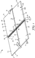
- a foldable and unfoldable pop-up article as disclosed herein comprises a primary folding axis 10, and at least one secondary folding axis 20, which is oriented at an angle (e.g., an included angle alpha ( ⁇ ) as shown in Fig. 1 ) that is at least about 30 degrees away from primary folding axis 10.
- the angle between a secondary folding axis 20 and a primary folding axis 10 may be at least about 50 or 70 degrees.
- a secondary folding axis 20 may be oriented within plus or minus 10, 5, or 2 degrees of orthogonal (perpendicular) to primary folding axis 10, noting that an orthogonal relationship (i.e., with an angle ⁇ of approximately 90 degrees) is shown in Fig. 1 .
- only a single secondary folding axis 20 may be present (as in Fig. 1 ).
- the dimension of a foldable and unfoldable pop-up article that is at least generally orthogonal to primary folding axis 10 (which dimension, in some embodiments, may be at least generally parallel to a secondary folding axis 20) will be referred to as the length of the article, and the dimension of the article that is generally parallel to axis 10 will be referred to as the width of the article. It will be appreciated, however, that these designations are arbitrary and that the length and width of such an article could be similar or identical; or, in some cases, the width dimension could be longer than the length dimension. Yet again for convenience of description, certain portions, edges, etc.
- article 1 comprises a backing 2 as described herein, and comprises primary folding axis 10 that extends the width of backing 2, from first major horizontal edge 24 of backing 2 to second major horizontal edge 25 of backing 2.
- primary folding axis 10 may be provided by way of one or more hinged connections 31 in backing 2 (noting that such a hinged connection does not necessarily have to extend the width of backing 2 to provide a folding axis that extends the width of backing 2).
- a folding axis is meant an axis about which two portions of backing 2 of article 1, which portions are hingedly connected generally along at least portions of the axis, can be rotated relative to each other.
- folding axis 10 and hinged connection 31 thereof may divide backing 2 e.g. into first and second major vertical portions 11 and 12 that are rotatable relative to each other about primary folding axis 10.
- article 1 further comprises secondary folding axis 20 that is orthogonal to primary folding axis 10 and that extends the length of backing 2, from first major vertical edge 14 to second major vertical edge 15 (noting that such a hinged connection does not necessarily have to extend the length of backing 2 to provide a folding axis that extends the length of backing 2).
- Secondary folding axis 20 may be provided by way of one or more hinged connections 32 in backing 2, and may divide backing 2 e.g. into first and second major horizontal portions 21 and 22 that are rotatable relative to each other about secondary folding axis 20. Folding axes 10 and 20 may thus collectively divide backing 2 into four major quadrants, designated in Fig.
- Quadrants 111, 112, 221, and 222 collectively provide first major horizontal portion 21; quadrants 111 and 221 collectively provide first major vertical portion 11, quadrants 221 and 222 collectively provide second major horizontal portion 22, and quadrants 112 and 222 collectively provide second major vertical portion 12. While in the exemplary embodiment of Fig. 1 , all of these quadrants are depicted as approximately equal in size, this does not necessarily have to be true in all embodiments. Likewise, first and second major vertical portions 11 and 12 may be, but do not have to be, generally, substantially, or strictly equal to each other in size. Likewise, first and second major horizontal portions 21 and 22 may, but do not have to be, generally, substantially, or strictly equal to each other in size.
- Backing 2 of such an article may be made of any suitable material, e.g. paperboard, plastic, etc. Often, backing 2 may be made of paperboard, e.g. in a thickness range of about 0.3 mm to about 5 mm. In some embodiments, backing 2 may be made of a rigid material. By this it is not meant that backing 2 must be absolutely unbendable; rather, it is meant that backing 2 is made of a material that is sufficiently stiff that portions of backing 2 will not be significantly rotated relative to each other during ordinary use (i.e., while being manipulated by hand by a user), except as provided by the herein-described hinged connections.
- quadrant 111 and quadrant 112 of first major horizontal portion 21 will each remain in a generally planar (flat) configuration, even as the quadrants may be rotated relative to each other about folding axis 10/hinged connection 31.
- a level of stiffness/rigidity may be achieved e.g. by making backing 2 of paperboard of thickness at least about 1 mm. In further embodiments, backing 2 may be made of paperboard of thickness at least about 2 mm.
- Hinged connections may be provided in backing 2 in any suitable manner.
- backing 2 may comprise a molded polymeric sheet (e.g., a rigid sheet) having various portions with living hinges provided (e.g. as formed during molding of the sheet) therebetween so as to hingedly connect the various portions.
- backing 2 may comprise portions of sheet material that are hingedly connected by way of flexible films (e.g., adhesive tapes) that hingedly connect the various portions.
- backing 2 may comprise portions of sheet material that are hingedly connected by spiral-bound connections (akin to that found in spiral notebooks).
- such hinged connections may be provided by scoring a sheet material so as to provide score lines between portions of the material.
- Such scoring may comprise e.g. crush scoring, partial cutting, etc., in any suitable manner that can provide a score line that penetrates partially through the thickness of backing 2.
- a score line may penetrate into backing 2 from only one side, as shown in Fig. 1 ; or, it may penetrate into backing 2 from the other side, e.g. to enable a higher amount of rotation relative thereto).
- Any combination of the above-listed connections may be used.
- a hinged connection as described herein may be provided by any suitable method of forming or otherwise providing a line of weakness in backing 2, that permits portions, e.g.
- hinged connections Regardless of the specific type and design of the hinged connections, they should be configured so that at any intersection (crossing point) of e.g. a hinged connection of a primary folding axis and a hinged connection of a secondary folding axis, a hinged connection of a first secondary folding axis and a hinged connection of a second secondary folding axis (as discussed later herein), and so on, the presence of a former hinged connection should not unduly interfere with the ability to fold the backing about the latter hinged connection, and vice versa.
- a foldable and unfoldable pop-up article as disclosed herein comprises at least one tensioning member 50 that is provided on the rear side of backing 2.
- Tensioning member 50 comprises an elongated length with a long axis that is oriented at least 30 degrees away from the above-mentioned at least one secondary folding axis 20. (Such an orientation may be most easily ascertained when the article is in the first, open position).
- the long axis of member 50 may be oriented at least 50 or 70 degrees away from the at least one secondary folding axis 20.
- such an axis of member 50 may be oriented within plus or minus 10, 5, or 2 degrees of orthogonal (perpendicular) to a secondary folding axis 20, noting that an orthogonal relationship (i.e., with an angle ⁇ of approximately 90 degrees) is shown in Fig. 1 .
- the long axis of tensioning member 50 is oriented within 10, or 5 degrees of primary folding axis 10.
- tensioning member 50 may be strictly parallel to (i.e., within about two degrees of) primary folding axis 10.
- the tensioning member 50 is substantially aligned with primary folding axis 10 (i.e., rather than being displaced or offset from folding axis 10 along the length dimension of article 1).
- the tensioning member 50 is substantially or strictly aligned with primary folding axis 10 (with an at least substantially parallel and aligned relationship of tensioning member 50 and primary folding axis 10 being depicted in Fig. 1 ).
- one or more tensioning members may be provided that are displaced (along the length dimension of article 1) away from primary folding axis 10, so that such a tensioning member or members, while being at least generally parallel to primary folding axis 10, are not aligned therewith.
- tensioning member 50 is tensionably engaged with backing 2 at least at two spaced-apart locations (e.g., locations 51 and 52 as shown in Fig. 1 ), with an axis connecting the locations to each other being oriented at least 30 degrees away from at least one secondary folding axis 20.
- an axis connecting engagement locations 51 and 52 will often be aligned with the long axis of tensioning member 50.
- such an axis may be oriented at least 50, 60, or 70 degrees away from at least one secondary folding axis 20.
- such an axis may be oriented within plus or minus 10, 5, or 2 degrees of orthogonal (perpendicular) to a secondary folding axis 20.
- Engagement locations 51 and 52 may advantageously be, but do not necessarily have to be, respectively located proximal to (e.g., with 1 cm of) first and second horizontal edges 24 and 25 of backing 2. All that is necessary is that at locations 51 and 52, tensioning member 50 is configured to engage with (e.g., contact) backing 2 in order to satisfactorily apply tension to backing 2 to promote the folding of backing 2 into a popped-up position as explained in detail herein.
- tensioning member 50 With article 1 in a first, open position, tensioning member 50 will thus be in a tensioned (e.g., stretched) condition so as to apply a pulling force to backing 2 at locations 51 and 52, which pulling force will motivate these locations of backing 2 to be brought closer together toward each other and will promote the folding of article 1 into a popped-up position as discussed herein.
- tensioned e.g., stretched
- first and second major vertical portions 11 and 12 form an included angle to each other (angle theta ( ⁇ ) as shown in Fig. 2 ) that is from about 130 degrees to about 0 degrees (the vertex of such an included angle may often, but does not necessarily have to, fall at or near folding axis 10).
- angle theta ⁇
- the first, open position in which portions 11 and 12 are substantially parallel to each other so that such an "included angle" theta will be in the range of 180 degrees.
- the second position may be a substantially closed position, in which the included angle theta between first and second major vertical portions 11 and 12 is from about 20 to about 0 degrees. (The included angle of Fig. 2 appears to be less than 20 degrees, so that strictly speaking this particular generally closed position is a substantially closed position).
- the closing of article 1 from a first, open position to a second, generally or substantially closed position can be likened to the closing of an open book (with folding axis 10 generally corresponding to the spine of the book).
- tensioning member 50 being substantially aligned with primary folding axis 10 about which the rotational movement of first and second vertical portions 11 and 12 relative to each other takes place, often may not affect (that is, may neither impede nor promote) the closing of article 1 from an open position to a closed position nor the opening of article 1 from a closed position to an open position.
- the closing of article 1 in this manner may cause an area of major front surface 41 that is on first major vertical portion 11 of article 1 to be brought into an at least generally facing relationship with an area of major front surface 41 that is on second major vertical portion 12 of article 1.
- a generally facing relationship is meant that an axis extended normal to an area of front surface 41 of first major vertical portion 11 (in a direction that does not pass through backing 2 within portion 11) will eventually contact second major vertical portion 12, and vice versa.
- An article as disclosed herein may be folded from the first, open position, into a third, popped-up position.
- this may be done by rotating first and second major horizontal portions 21 and 22 relative to each other about secondary folding axis 20.
- First horizontal portion 21 may be moved as illustrated by arrow 23; second horizontal portion 22 may be moved as illustrated by arrow 26; or some combination of both may occur.
- An exemplary popped-up position is depicted in Fig. 3 (which is a perspective view from a similar vantage point as Fig. 1 ).
- first and second major horizontal portions 21 and 22 form an included angle to each other (angle beta ( ⁇ ) as shown in Fig. 3 ) that is from about 130 degrees to about 30 degrees (the vertex of such an included angle may often, but does not necessarily have to, fall at or near folding axis 20).
- angle beta ⁇
- the vertex of such an included angle may often, but does not necessarily have to, fall at or near folding axis 20.
- first and second major horizontal portions may form an included angle of from about 70 degrees to about 110 degrees, which may optimally enhance the stability of article 1 when resting on a gravitationally-horizontal surface in the third, popped-up position, as discussed later herein.
- the folding of article 1 in this manner may cause an area of major rear surface 45 that is on first major horizontal portion 21 of article 1 to be brought into an at least generally facing relationship with an area of major rear surface 45 that is on second major horizontal portion 22 of article 1.
- a generally facing relationship is meant that an axis extended normal to an area of rear surface 45 of first major horizontal portion 21 (in a direction that does not pass through backing 2 within portion 21) will eventually contact second major horizontal portion 12, and vice versa.
- tensioning member 50 may merely provide a slight assist to the act of manually (i.e., by hand by a user) folding the article from the first, open position to the third, popped up position.
- tensioning member 50 may be to maintain the article in its popped-up position.
- tensioning member 50 may exert sufficient tensioning force on backing 2 to bias the article toward the third, popped-up position so that when the article is in the first, open position, the article will spontaneously (that is, without assistance from a user) fold into the third, popped-up position unless an outside force (e.g., applied by the user) is exerted on the article to prevent it from folding into the third, popped-up position.
- the article may comprise one or more protrusions that extend rearwardly (away from backing 2) from rear surface 45 of backing 2 at a location at or near folding axis 20.
- Such a protrusion may extend e.g. a few mm, so that when the article is placed into the first, open position on a horizontal surface, the protrusion may cause gravitational force to slightly fold the article toward the third, popped-up position (e.g., rather than being strictly planar), which may make it easier for the article to be urged into the third, popped-up position by the tensioning force of member 50.
- tensioning member 50 may be tensioned sufficiently to prevent the article from collapsing (unfolding) from the third, popped-up position, into the first, open position, under the force of the Earth's gravity.
- Such an article may be supplied to a user, e.g. with the article in a second, generally or substantially closed condition (e.g., in "brook” form).
- the user may e.g. transport or store the article in that position.
- backing 2 may serve to protect any contents of the article that may be present on first (front) major side 40 of the article.
- a user can unfold the article from the second position, into the above-described first (open) position.
- the article can then be folded from the first position into the third, popped-up position (which process might be spontaneously performed by the article without outside help, or may be facilitated by the user).
- first major (front) side 40 of the article When desired, the article can be unfolded from the third, popped-up position (by manually overcoming the tensioning force exerted by tensioning member 50) into the first, open position, and can then be folded into the second, closed position as desired.
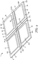
- FIG. 4 is depicted another exemplary article 1 in a first, open position, which article 1 is generally similar in design and function to that shown in Figs. 1-3 , but with certain features and functions that may be advantageous in some circumstances (in Fig. 4 , tensioning member 50 is omitted for ease of presentation).
- first, second, third and fourth notepads 113, 114, 223, and 224 are provided respectively in first, second, third and fourth quadrants 111, 112, 221, and 222 of article 1.
- Primary and secondary folding axes 10 and 20, and hinged connections thereof, are arranged to pass in between the notepads of neighboring quadrants, so that the presence of the notepads does not interfere with folding and unfolding of the various major portions of the article about the various folding axes.
- primary folding axis 10 is a compound folding axis.
- hinged connection 31 that provides primary folding axis 10 is a compound hinged connection comprised of two parallel hinged sub-connections 31a and 31b.
- a vertical spacer strip 33 is provided between sub-connections 31a and 31b.
- Such sub-connections may be provided in the same manner as described elsewhere herein, e.g. by the use of score lines that penetrate partway through the thickness of backing 2).
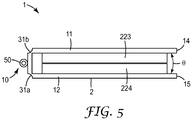
- the providing of such a compound folding axis/compound hinged connection with a vertical spacer strip therebetween may allow article 1 to be folded about folding axis 10 into a second, substantially closed position as shown in Fig. 5 . From Fig.
- first, vertical spacer strip 33 may comprise a width between parallel hinged sub-connections 31a and 31b that is from about 80% to about 150% of the combined thickness of first and second notepads that are mounted on the front side of article 1 and that are brought into a generally face-to-face configuration when article 1 is folded into a second, substantially closed position. It will be appreciated that the front surfaces of two such notepads may contact each other in such a case.
- secondary folding axis 20 may be a compound folding axis, as shown in Fig. 4 .
- secondary hinged connection 32 that provides secondary folding axis 20 may be a compound hinged connection that is comprised of two parallel hinged sub-connections 32a and 32b with a horizontal spacer strip 34 provided therebetween.
- article 1 when article 1 is folded into the third, popped-up position, it may form a modified A-frame shape, e.g. with horizontal spacer strip 34 forming an apex of the A-frame (which apex may comprise a more flat-topped or truncated appearance than the apex shown in Fig. 3 ).
- either, neither, or both of primary and secondary folding axes 10 and 20 may be a compound folding axis.
- Article 1 may comprise (e.g., mounted on first, front side 40 of backing 2) any content, such as e.g. a component, item, indicia, decorative pattern, etc., that it might be desired to present when article 1 is folded into the third, popped-up position.
- any content such as e.g. a component, item, indicia, decorative pattern, etc.
- Such a notepad (which can be mounted to front side 40 of backing 2 in any suitable manner) may comprise e.g. a stack of releasably bound paper sheets that are bound to each other at one end so that individual sheets can be removed from the stack.
- each paper sheet may comprise an area that is backed by adhesive, e.g.
- article 1 may thus be used to display and/or dispense paper notes of any type. Similarly, article 1 may be used to present, display and/or dispense various flags, tabs, markers, etc., as are often used to mark pages, documents and the like.
- article 1 may be used to present, display and/or dispense any item(s) that can be provided in a suitable holder on the front side of article 1.
- a suitable holder on the front side of article 1.
- one or more holders (which might be as simple as an envelope or sleeve, or which might be a more complex dispensing container holding e.g. z-folded or fan-folded sheets of paper, flags, etc.) may be mounted on the front side of article 1, e.g. in one of the aforementioned quadrants.
- Such a holder might contain e.g. business cards, coupons, advertisements, novelty items, and so on, which may be removed from the holder if desired.
- such a holder may be opaque, or may be transparent if visibility of the held items is desired.
- article 1 might contain an actuator such that folding article 1 into a popped-up position causes an item to be partially ejected its holder so as to more easily be displayed or removed.
- at least some portion of front side 40 of article 1 may comprise an informational indicia and/or a decorative display rather than presenting an item or items that can be removed therefrom.
- one or more quadrants of front side 40 of article 1 may have printed upon the front surface 41 thereof, various informational indicia, decorative patterns, and so on.
- a first side of an article 1 (e.g., the near side of article 1 as viewed in Fig. 3 ) might have one or more notepads etc. mounted thereupon, while a second side of an article (e.g., the far surface of major portion 21 of article 1 as viewed in Fig. 3 ) might have a user's name presented thereon.
- Such an article might serve e.g. as an identifying placard of the type often used in meetings, classes, seminars, and the like, and so might bear the user's name (and, optionally, the user's affiliation or other information) on the second side so as to be visible by others, and might also bear one or more notepads, business card holders, etc., on the first side.
- the second side of such an article might comprise one or more holders (e.g., transparent sleeves) into which a placard (e.g., a printed placard bearing the name of the user) might be inserted.
- a placard e.g., a printed placard bearing the name of the user
- Such a holder or holder may of course be configured so as to not interfere with the aforementioned closing of article 1 into the second, closed position.
- Article 1 may be configured so that any such dispensable items may be refilled; or, article 1 may be designed to be disposed once such dispensable items are exhausted.
- Tensioning member 50 can be made of any material that can be placed and held under tension in the required manner.
- such a tensioning member may be made of a material (e.g., certain metals or plastics) that is not inherently elastic but with elasticity being achieved by the mechanical design of the structure (e.g., by forming metal into a coil spring configuration).
- tensioning member 50 may be comprised of a spring (e.g., a coil spring) as exemplified in Fig. 1 .
- Such a spring might be made of any suitable plastic or metal (e.g., steel, brass, and so on), with the parameters of the spring (e.g., length, coil pitch, coil diameter, spring constant, and so on), being chosen for the design of a particular article 1.
- suitable plastic or metal e.g., steel, brass, and so on
- the parameters of the spring e.g., length, coil pitch, coil diameter, spring constant, and so on
- tensioning member 50 may be comprised of an intrinsically elastic material such as e.g. an elastomeric polymeric material (e.g., a rubber strip, rubber band, bungee, or the like). Combinations of the two approaches may be used, of course.
- the tensioning force provided by tensioning member 50 may set as desired e.g. by the choice of the elastomeric material from which member 50 is made, and/or by the design parameters of tensioning member 50 (e.g., diameter of the member, and so on).
- such an elastomeric material be chosen to have a low creep (e.g., so that tensioning member 50 retains the desired tensioning ability even if article 1 is stored for long periods of time with member 50 in a stretched condition (e.g., if article 1 is kept in the second, closed position for extended periods of time)).
- Tensioning member 50 may be, but does not necessarily have to be, attached to backing 2 at locations 51 and 52 at which tensioning member 50 is tensionably engaged with backing. All that is necessary is that tensioning member 50 is tensionably engaged with (i.e., is in contact with so as to be able to exert a pulling force on) to backing 2 in those locations so as to be able to promote the folding of backing 2 into a popped-up position.
- tensioning member 50 e.g., terminal ends of member 50
- Such attachment might be achieved by any suitable attachment mechanism, whether by mechanical attachment (e.g., by one or more staples, rivets, clips, or the like, or by tying, etc.), or by chemical/adhesive attachment (e.g., by use of an adhesive tape, a liquid adhesive, solder, etc.)
- tensioning member 50 may not necessarily need to be attached (e.g., bonded or mechanically fastened) to backing 2 at locations 51 and 52 is shown in Fig. 6 .
- This example is also one in which tensioning member 50 is provided in the form of a continuous elastic band or loop (e.g., a rubber band type material) that is tensionably engaged with backing 2 at locations 51 and 52 with two (generally parallel) elongated portions of loop 50 extending therebetween (so that, in effect, two separate tensioning members 50a and 50b are provided).
- Backing 2 of exemplary article 1 of Fig. 6 is of generally similar overall design to that of Fig.
- Continuous loop tensioning member 50 can be extended along the rearward side of backing 2 as shown in Fig. 6 , and portion 53a of loop member 50 can be passed forwardly through notches 35a and 35b so that portion 53a of tensioning loop 50 is positioned on the frontward side of backing 2 e.g. in a location generally proximal to first horizontal edge 24.
- Portion 53b of loop member 50 can similarly be passed through notches 37a and 37b and positioned on the frontward side of backing 2 e.g.
- notches 35a and 37a are shown as aligned with hinged connection 31a; likewise notches 35b and 37b are shown as aligned with hinged connection 31b. However, such notches do not necessarily have to be aligned with a hinged connection.
- continuous loop tensioning member 50 can be mounted on backing 2, with member 50 tensionably engaging backing 2 at locations 51 and 52 (which locations may be defined e.g. by the terminal, closed ends of the notches). Moreover, this may be done without any attachment mechanism (e.g., adhesive or mechanical attachment) necessarily being used to attach member 50 to backing 2, whether at locations 51 and 52 or anywhere along the extent of member 50. In other words, in some embodiments tensioning member 50 may be held in position on backing 2 by the contractive force of the tensioning member itself; however, an attachment mechanism may be used to augment this if desired.
- attachment mechanism e.g., adhesive or mechanical attachment
- a tensioning member 50 may not necessarily be a continuous loop but may rather comprise a linear segment with a loop at each end thereof, each loop being designed e.g. to fit over a stanchion that is located proximal a horizontal edge of the backing.
- a tensioning member may be an elastic member an end of which is wrapped around an edge (e.g., edge 24 or 25) of backing 2 and then attached to the front side of the backing, with the location at which the member wraps around the edge thus forming an engaging location without the member necessarily being attached to the backing at that location.
- a tensioning member 50 may be contained within a cover or sleeve (which may serve a function that is protective, decorative, or both).
- a tensioning member 50 e.g., one or both ends thereof, if such ends exist; or, a portion of a continuous loop member
- backing 2 may be removably engaged with (e.g., attached to) backing 2 so as to be removable from, and/or re-engagable with, backing 2 as desired.
- multiple engagement locations and/or attachment points may be provided so that the tensioning of member 50 (i.e., the amount to which it is stretched when article 1 is placed in the first, open position) may be altered as desired.
- no portion of tensioning member that lies between engagement locations 51 and 52 is attached to backing 2.
- a foldable and unfoldable pop-up article 1 as disclosed herein comprises at least a primary folding axis, and further comprises at least one secondary folding axis that is oriented at an angle that is at least about 30 degrees away from the primary folding axis.
- the above-discussed illustrative embodiment of Figs. 1-6 depicts a general type of article 1 comprising a primary folding axis 10 and a single secondary folding axis 20 that is oriented at least generally orthogonally to primary folding axis 10.
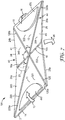
- Fig. 7 depicts in exemplary embodiment another general type of a foldable and unfoldable pop-up article 101 (in perspective view, from the front side, with the article in a first, open position).
- a tensioning member 50 is omitted from Fig. 7 for ease of presentation of other components and relationships, but it will be understood that any of the above-described tensioning members (e.g. member 50 of Fig. 1 , or member 50 of Fig. 6 , similarly positioned as in those Figures) could be used.
- Article 101 of Fig. 7 comprises a primary folding axis 10, and further comprises two (i.e., first and second) secondary folding axes 120 and 220.
- the (included) angle between first secondary folding axis 120 and primary folding axis 10 may be at least about 30, 40, or 50 degrees. In further embodiments, this angle may be at most about 80, 70 or 60 degrees.
- the angle between second secondary folding axis 220 and primary folding axis 10 e.g. angle epsilon ( ⁇ ) of Fig. 7
- the included angle between the first and second secondary folding axes e.g. angle delta ( ⁇ ) of Fig.
- First and second secondary folding axes 120 and 220 may be, but do not necessarily have to be, present in a symmetrical pattern (i.e., with angles gamma and epsilon being similar or equal to each other and/or with axes 120 and 220 intersecting each other at a common intersection with primary folding axis 10, e.g. as depicted in the exemplary embodiment of Fig. 7 ).
- First and second secondary folding axes may, but do not necessarily have to, terminate in corners of backing 2 of article 1 (as in Fig. 7 ).
- Article 101 of Fig. 7 can be folded about primary folding axis 10 into a second, closed position, in generally similar manner as described previously herein (in which closed position it may comprise a shape similar an isosceles trapezoid).
- exemplary article 101 may comprise several differences from exemplary article 1 which may be most evident when article 101 is in the third, popped-up position.
- first secondary folding axis 120 of article 101 may comprise two linear segments 120a and 120b that, when article 101 is in the third, popped-up position, are not co-linear with each other, but rather meet at an angle (e.g. at their intersection with primary folding axis 10).
- segments 220a and 220b of second secondary folding axis 220 This may be contrasted with secondary folding axis 20 of article 1 of Fig. 1 , which folding axis may remain generally linear along its entire extent when the article is in the third, popped-up position.
- horizontal edges 24 and 25 of article 101 may each comprise two segments (e.g., 24a and 24b, and 25a and 25b) that are each generally linear and that meet at or near primary folding axis 10, in similar manner to the corresponding horizontal edges of article 1.
- the two segments of each horizontal edge are angled with respect to each other so that article 101 (when in the first position) comprises a generally "bow-tie" shape as seen in Fig. 7 (i.e., rather than the rectangular shape of article 1 in Fig. 1 ).
- folding article 1 about first and second secondary folding axes 120 and 220 will draw the centermost portion of horizontal edge 24 and the centermost portion of horizontal edge 25 closer together to each other, while leaving the outermost portions of these horizontal edges (i.e., those portions proximal to vertical edges 14 and 15) less drawn together.
- the two major vertical edges 14 and 15 may not necessarily be placed into an A-frame configuration as happens with article 1 of Fig. 1 . Rather, major edges 14 and 15 of article 101 may each remain generally, or strictly, linear.
- folding article 101 into a third, popped-up position may result in the preferential drawingtogether of the horizontally centermost portions of edges 24 and 25 of the article (e.g., along a direction generally parallel to primary folding axis 10), causing the article to assume a more pronounced bow-tie shape (e.g. when viewed from above front side 40 of the article).
- article 101 when in the third, popped-up position, article 101 may present two major front-side faces 321 and 322, each of which may be generally triangular in shape and which may face generally along the length dimension of article 101 (that is, such faces may comprise a normal axis that is oriented generally parallel to the length dimension of article 101 when viewed from above).
- This arrangement may be contrasted to the embodiment of Figs. 1-3 , in which no such length-dimension-facing faces, of any shape, are present when article 1 is in the third, popped-up position.
- article 101 may also comprise first and second minor faces 333 and 334 (the first being defined by folding axis segments 10b and 120a, and edge segment 25a; the second being defined by folding axis segments 10b and 220b, and edge segment 25b).
- article 101 may comprise third and fourth minor faces 345 and 346, the first being defined by folding axis segments 10a and 220a, and edge segment 24a; the second being defined by folding axis segments 10a and 120b, and edge segment 24b. All of these minor faces may be generally triangular in shape and may, but do not have to be, generally similar in shape and/or size with each other.
- any of the faces of article 101 may comprise any desired item mounted thereon.
- faces 321 and 322 each comprise a notepad stack (numbered 447 and 478 respectively) which may optionally be shaped so as to optimally fit within area 321 or 322, e.g. as shown in Fig. 7 .
- a foldable and unfoldable pop-up article as disclosed herein may be of any suitable size.
- such an article may be of nominal 25 cm x 15 cm size when in the first, open position.
- primary folding axis 10 and/or secondary folding axis 20 may fall, but do not necessarily have to fall, on an axis of symmetry of article 1 when it is in the first, open position.
- Such an article may or may not be configured so that vertical portions 11 and 12 can be rotated about primary folding axis 10, from the first, open position, in a retrograde direction away from the second, closed position (that is, in a direction opposite that indicated by arrows 13 and 16 of Fig. 1 ).
- such an article may or may not be configured to prevent retrograde rotation of horizontal portions 21 and 22 about secondary folding axis 20 past the first, open position in a direction away from the third, popped-up position.
- a stop feature may be provided in article 1 to limit the rotation of the horizontal portions 21 and 22 about secondary folding axis 20 toward the third, popped-up position (as motivated by tensioning member 50) to a desired angle. Any of these features may likewise be provided on article 101 with respect to rotation about primary folding axis 10 and/or first and second secondary folding axes 120 and 220.
- such an article may comprise a locking mechanism (exemplified by snap/strap 17 and socket 18 of Fig. 1 ) that may secure the article in the second, generally closed position.
- An analogous locking mechanism (not shown in any Figure) may likewise be used to secure the article in the third, popped-up position if desired.
- Rear surface 44 of backing 2 may be a decorative surface, which may comprise any desired solid color, decorative pattern or patterns, informational indicia, or combination thereof.
- rear surface 44 may be provided by a cover (e.g., a vinyl, cloth or leather cover of the type often used on books and the like) that may at least partially wrap around onto at least an edge (perimeter) portion of front surface 41.
- front surface 41 e.g., at least areas thereof that are not obscured by items mounted to front side 40 of article 1 may thus bear any desired decorative pattern, informational indicia, etc.
- horizontal edges 24 and 25 may comprise any suitable treatment, coating or the like, which may increase the frictional interaction of edges 24 and 25 with a gravitationally-horizontal surface 27 and thus which may enhance the stability of the article when resting upon such a surface in the third, popped-up position.
- a treatment might comprise a directionally-oriented treatment which might preferentially allow the motion of edges 24 and 25 across such a surface in a direction toward the third, popped-up position, but which might preferentially resist the motion of edges 24 and 25 across such a surface in an opposite direction.
- major portions of horizontal edges 24 and 25, and/or of vertical edges 14 and 15, may be strictly linear (except as interrupted e.g. by notches which, as discussed earlier, may serve e.g. to accept and seat portions of a tensioning member).
- any or all of such edges may comprise non-linear (e.g., scalloped, arcuate, etc.) portions.
- a foldable and unfoldable pop-up article as disclosed herein may comprise a "signpost" item exemplified by component 225 of Fig. 6 .
- a signpost item When the article is in the first, open position, such a signpost item may extend across a single secondary folding axis (e.g., axis 20 of Fig. 6 ); or, if multiple secondary folding axes are present, such an item may extend across one or both of the secondary folding axes.
- a signpost item When the article is folded into the third, popped-up position, such a signpost item may extend generally upward (e.g., with respect to article 1 of Fig.
- Such an item might be e.g. a tab or flap (as exemplified by item 225 of Fig. 6 , of any suitable shape or form); might be, or might contain, one or more removable items; might be a notepad, and so on, as desired.
- a signpost item might bear any suitable informational indicia, decorative pattern, and so on.
- the dimension of such a signpost item or items across a portion of the backing upon which the signpost item is mounted may be greater than the distance from the horizontal edge of the backing to the secondary folding axis of the backing, without necessitating that the item be folded during storage or use of the article (e.g., as with item 225 of Fig. 6 ).
- a product was obtained from 3M Company, St. Paul, MN under the trade designation POST-IT 4" X 6" Flower Burst Hard Cover Book.
- the product resembled a conventional hard-cover book (of size approximately 25 cm x 16.5 cm inches when fully opened, and approximately 16.5 cm x 11.5 cm when fully closed).
- the cover of the book was a rigid paperboard backing of thickness approximately 2 mm, with a decorative flower pattern on the outside of the cover.
- First and second parallel hinged sub-connections (of the general type exemplified by hinged sub-connections 31a and 31b of Fig. 4 , except that they penetrated into the rigid paperboard from both sides) were present in the product as obtained.
- the first and second hinged sub-connections were spaced at a distance of approximately 16 mm apart with a spacer strip therebetween, which formed the spine of the book.
- the product contained a single notepad (of nominal dimension 10 cm x 15 cm, and of nominal thickness 11 mm) attached to the inside of one leaf of the cover.
- the single notepad was detached from the product and removed.
- Four notepads (obtained from 3M Company under the trade designation POST-IT) were obtained, each comprising a stack of paper sheets of total thickness about 5 mm and each measuring approximately 10 cm x 7.5 cm.
- the four notepads were attached to the inside cover of the book (two on each leaf), with the short axis of each notepad being aligned with the first and hinged sub-connections.
- a gap of about 8 mm was left between each hinged sub-connection and the closest terminal edge of a notepad.
- a gap of about 14 mm was left between the upper and lower notepads of each leaf.
- Two parallel score lines as formed by cutting through approximately 90 % of the thickness of the rigid paperboard backing (cover) with a blade, were formed in the rigid paperboard backing, extending from one major edge of the backing to the other major edge, in a direction approximately orthogonal to the existing hinged sub-connections and passing between the upper and lower pairs of notepads.
- the score lines were approximately 13 mm apart and served to provide hinged sub-connections of a secondary folding axis of the finished article, akin to hinged sub-connections 32a and 32b of Fig. 4 . (The above-mentioned first and second hinged sub-connections served to provide a primary folding axis of the finished article.)
- a metal spring was obtained, of coil diameter approximately 2 mm and of a resting (untensioned) length estimated to be in the range of approximately 3-4 inches. Each end of the spring was attached to a straight metal cotter of length approximately 15 mm and of diameter approximately 1.5 mm.
- a second, corresponding hole was drilled at the other end of the spine of the book.
- the metal cotters were then passed endwise through the holes and rotated so that they could not pass back therethrough, so as to secure the coil spring to the cover, with the spring being on the rear side of the cover (i.e., on the side opposite the four notepads).
- a finished article was produced that was generally similar to that shown in Fig. 4 (except that Fig. 4 does not show the tensioning member or the hole/cotter method of attaching the member to the backing that was used in the Representative Working Example).
- the finished article could be carried, stored, etc., while in the second, closed position (that is, in a book format). When desired, it could be opened (i.e., unfolded about the primary folding axis) into a flat, first position.
- the article Upon this being done (with the article e.g. lying on a surface such as a desktop), the article would, under the motivating force of the spring, spontaneously fold about the secondary folding axis into a popped-up position of the general type shown in Fig. 3 .
- the spring served to maintain the article in this popped-up position (that is, the article did not collapse back into the first, open position under the influence of gravity).
- the thus-produced article comprised a continuous loop tensioning member arranged in the general manner depicted in Fig. 6 .
- the article comprised a bow-tie design of the general type depicted in Fig. 7 .
- two springs were arranged in series and connected end-to-end to collectively provide a suitable tensioning member.
- the article comprised a rearwardly-protruding bump on the spine of the article, which served to further promote the spontaneous folding of the article into the third, popped-up position when the article was placed on a surface in the first, open position.
- the article comprised a non-rigid backing rather than a the above-described rigid backing (that is, the article was more akin to a soft-cover, paperback book or pamphlet than to a hard-cover book).
Landscapes
- Purses, Travelling Bags, Baskets, Or Suitcases (AREA)
- Credit Cards Or The Like (AREA)
- Toys (AREA)
- Cartons (AREA)
- Sheet Holders (AREA)
Applications Claiming Priority (2)
| Application Number | Priority Date | Filing Date | Title |
|---|---|---|---|
| US13/545,121 US8985633B2 (en) | 2012-07-10 | 2012-07-10 | Foldable pop-up article |
| PCT/US2013/045310 WO2014011342A1 (en) | 2012-07-10 | 2013-06-12 | Foldable pop-up article |
Publications (3)
| Publication Number | Publication Date |
|---|---|
| EP2872341A1 EP2872341A1 (en) | 2015-05-20 |
| EP2872341A4 EP2872341A4 (en) | 2016-02-24 |
| EP2872341B1 true EP2872341B1 (en) | 2017-04-26 |
Family
ID=49913040
Family Applications (1)
| Application Number | Title | Priority Date | Filing Date |
|---|---|---|---|
| EP13817565.8A Not-in-force EP2872341B1 (en) | 2012-07-10 | 2013-06-12 | Foldable pop-up article |
Country Status (5)
| Country | Link |
|---|---|
| US (1) | US8985633B2 (enExample) |
| EP (1) | EP2872341B1 (enExample) |
| JP (1) | JP6320377B2 (enExample) |
| MX (1) | MX358150B (enExample) |
| WO (1) | WO2014011342A1 (enExample) |
Families Citing this family (3)
| Publication number | Priority date | Publication date | Assignee | Title |
|---|---|---|---|---|
| US9451818B2 (en) * | 2014-04-17 | 2016-09-27 | Rakuten Kobo, Inc. | Portable computing device case convertible to upright stand |
| KR20170004387U (ko) * | 2016-06-20 | 2017-12-28 | (주)라이브워크 | 물품 거치 장치 |
| FR3141043A1 (fr) * | 2022-10-20 | 2024-04-26 | fabrice frerot | Etui à lunettes repliable |
Family Cites Families (20)
| Publication number | Priority date | Publication date | Assignee | Title |
|---|---|---|---|---|
| US2831279A (en) * | 1956-08-17 | 1958-04-22 | Brown & Bigelow | Calendar handbook |
| JPS60127968U (ja) * | 1984-02-06 | 1985-08-28 | 蓮沼 珠真子 | 英語学習用カ−ド入れ |
| JPS63178940A (ja) * | 1987-01-14 | 1988-07-23 | 大和紙工株式会社 | 折畳箱及びそれを利用した整理システム |
| US4787653A (en) * | 1987-06-22 | 1988-11-29 | Stewart Jr Robert B | Non-buckling newspaper and device for the production thereof |
| US4861073A (en) * | 1988-04-26 | 1989-08-29 | Leonid Poretsky | Newspaper holder |
| US5407231A (en) | 1990-04-09 | 1995-04-18 | Productive Environments, Inc. | Windowing leaf structure |
| US5295089A (en) * | 1992-05-28 | 1994-03-15 | Emilio Ambasz | Soft, foldable consumer electronic products |
| US5332265A (en) * | 1993-01-22 | 1994-07-26 | Minnesota Mining And Manufacturing Company | Advertising assembly |
| US5375885A (en) * | 1994-04-29 | 1994-12-27 | Abercrombie; Robert N. | Combination bookmark and page prop device |
| US5868429A (en) * | 1995-02-03 | 1999-02-09 | Rand Mcnally & Company | Multidirectional multiple fold laminated product and method of making |
| US6629800B1 (en) * | 2001-02-02 | 2003-10-07 | Streetwise Maps Inc. | Foldable map book |
| TW510306U (en) * | 2001-08-29 | 2002-11-11 | Chiun-Chau Lin | Improved jacket board structure for notebook and files folder capable of adjusting inclination stand |
| US6749084B2 (en) | 2002-03-11 | 2004-06-15 | 3M Innovative Properties Company | Plate spring for pop-up sheet material dispenser |
| US6702330B2 (en) | 2002-06-18 | 2004-03-09 | Robert John Roca | Book with hidden spine |
| JP2005199675A (ja) * | 2004-01-14 | 2005-07-28 | Kiyohara:Kk | カード収納体 |
| US20050258060A1 (en) | 2004-05-06 | 2005-11-24 | Jonathan Katz | Pop-up package assembly for a flat product and method of packaging |
| US7726695B2 (en) | 2004-10-26 | 2010-06-01 | Meadwestvaco Corporation | Wire concealing cover for wirebound books |
| US20080073897A1 (en) | 2006-09-22 | 2008-03-27 | Umbra Llc | Pop-up photo album |
| US8359078B2 (en) * | 2009-05-29 | 2013-01-22 | Belkin International, Inc. | Mobile media device enclosure, method of use of mobile media device enclosure, and method of providing mobile media device enclosure |
| KR100942784B1 (ko) | 2009-11-04 | 2010-02-18 | (주)명지문화 | 더블형 합지판을 통한 눈높이 조절이 가능한 탁상용 양면 칼렌더 및 그 제작방법 |
-
2012
- 2012-07-10 US US13/545,121 patent/US8985633B2/en not_active Expired - Fee Related
-
2013
- 2013-06-12 MX MX2015000384A patent/MX358150B/es active IP Right Grant
- 2013-06-12 EP EP13817565.8A patent/EP2872341B1/en not_active Not-in-force
- 2013-06-12 JP JP2015521623A patent/JP6320377B2/ja active Active
- 2013-06-12 WO PCT/US2013/045310 patent/WO2014011342A1/en not_active Ceased
Also Published As
| Publication number | Publication date |
|---|---|
| MX358150B (es) | 2018-08-07 |
| EP2872341A1 (en) | 2015-05-20 |
| US8985633B2 (en) | 2015-03-24 |
| CN104428141A (zh) | 2015-03-18 |
| EP2872341A4 (en) | 2016-02-24 |
| US20140014554A1 (en) | 2014-01-16 |
| JP6320377B2 (ja) | 2018-05-09 |
| JP2015530937A (ja) | 2015-10-29 |
| MX2015000384A (es) | 2015-04-10 |
| WO2014011342A1 (en) | 2014-01-16 |
Similar Documents
| Publication | Publication Date | Title |
|---|---|---|
| US12377676B2 (en) | Folder folder | |
| US8499478B1 (en) | Gift card presenter | |
| US5683111A (en) | Binder system and kit | |
| US5996881A (en) | Convertible folder | |
| EP1912197A1 (en) | Self-standing flat plate-like article and methods of exhibiting and manufacturing the same | |
| US6244627B1 (en) | Folder with overlapping windows | |
| US10486456B2 (en) | Component with selectively deployable tabs | |
| EP2872341B1 (en) | Foldable pop-up article | |
| US8104795B2 (en) | Expandable card form | |
| US6749228B2 (en) | Robust supported display folder | |
| US5575505A (en) | Pamphlet with enhanced spine | |
| US20060272185A1 (en) | Greeting card holder | |
| US20050253371A1 (en) | Scrapbooking supplies system | |
| US6499767B1 (en) | Presentation device with automatic extending support | |
| US7703808B2 (en) | Expandable business card | |
| KR20140041398A (ko) | 리프 인쇄물, 철 리프, 리프 제공 방법, 절첩 리프 인쇄물, 및 책 | |
| CN104428141B (zh) | 可折叠弹出式制品 | |
| US20070120360A1 (en) | Bound component with sticker sheets | |
| JP4602057B2 (ja) | ブックカバー | |
| JP2008265039A (ja) | 組立式卓上カレンダー立てシート及びカレンダーシート | |
| AU2006100007A4 (en) | A notebook | |
| GB2295357A (en) | A document file | |
| EP1139319A1 (en) | Foldable information and/or graphic sheet, and assembly obtained therefrom | |
| GB2392706A (en) | Fasteners | |
| WO2007099366A1 (en) | An information product |
Legal Events
| Date | Code | Title | Description |
|---|---|---|---|
| PUAI | Public reference made under article 153(3) epc to a published international application that has entered the european phase |
Free format text: ORIGINAL CODE: 0009012 |
|
| 17P | Request for examination filed |
Effective date: 20150119 |
|
| AK | Designated contracting states |
Kind code of ref document: A1 Designated state(s): AL AT BE BG CH CY CZ DE DK EE ES FI FR GB GR HR HU IE IS IT LI LT LU LV MC MK MT NL NO PL PT RO RS SE SI SK SM TR |
|
| AX | Request for extension of the european patent |
Extension state: BA ME |
|
| DAX | Request for extension of the european patent (deleted) | ||
| RA4 | Supplementary search report drawn up and despatched (corrected) |
Effective date: 20160125 |
|
| RIC1 | Information provided on ipc code assigned before grant |
Ipc: B42F 7/04 20060101AFI20160119BHEP Ipc: B42F 5/00 20060101ALI20160119BHEP Ipc: A45C 11/18 20060101ALI20160119BHEP Ipc: A63H 33/38 20060101ALI20160119BHEP Ipc: B42D 5/00 20060101ALI20160119BHEP |
|
| REG | Reference to a national code |
Ref country code: DE Ref legal event code: R079 Ref document number: 602013020415 Country of ref document: DE Free format text: PREVIOUS MAIN CLASS: B42F0007040000 Ipc: A45C0013000000 |
|
| GRAP | Despatch of communication of intention to grant a patent |
Free format text: ORIGINAL CODE: EPIDOSNIGR1 |
|
| STAA | Information on the status of an ep patent application or granted ep patent |
Free format text: STATUS: GRANT OF PATENT IS INTENDED |
|
| RIC1 | Information provided on ipc code assigned before grant |
Ipc: B42D 5/00 20060101ALI20161012BHEP Ipc: A45C 11/18 20060101ALI20161012BHEP Ipc: A45C 1/06 20060101ALI20161012BHEP Ipc: A45C 13/02 20060101ALI20161012BHEP Ipc: B42F 7/00 20060101ALI20161012BHEP Ipc: B42F 5/00 20060101ALI20161012BHEP Ipc: A45C 1/08 20060101ALI20161012BHEP Ipc: A45C 13/00 20060101AFI20161012BHEP Ipc: B42D 15/00 20060101ALI20161012BHEP |
|
| INTG | Intention to grant announced |
Effective date: 20161107 |
|
| GRAS | Grant fee paid |
Free format text: ORIGINAL CODE: EPIDOSNIGR3 |
|
| GRAA | (expected) grant |
Free format text: ORIGINAL CODE: 0009210 |
|
| STAA | Information on the status of an ep patent application or granted ep patent |
Free format text: STATUS: THE PATENT HAS BEEN GRANTED |
|
| AK | Designated contracting states |
Kind code of ref document: B1 Designated state(s): AL AT BE BG CH CY CZ DE DK EE ES FI FR GB GR HR HU IE IS IT LI LT LU LV MC MK MT NL NO PL PT RO RS SE SI SK SM TR |
|
| REG | Reference to a national code |
Ref country code: GB Ref legal event code: FG4D |
|
| REG | Reference to a national code |
Ref country code: CH Ref legal event code: EP |
|
| REG | Reference to a national code |
Ref country code: AT Ref legal event code: REF Ref document number: 887123 Country of ref document: AT Kind code of ref document: T Effective date: 20170515 |
|
| REG | Reference to a national code |
Ref country code: IE Ref legal event code: FG4D |
|
| REG | Reference to a national code |
Ref country code: DE Ref legal event code: R096 Ref document number: 602013020415 Country of ref document: DE |
|
| REG | Reference to a national code |
Ref country code: NL Ref legal event code: MP Effective date: 20170426 |
|
| REG | Reference to a national code |
Ref country code: LT Ref legal event code: MG4D |
|
| REG | Reference to a national code |
Ref country code: AT Ref legal event code: MK05 Ref document number: 887123 Country of ref document: AT Kind code of ref document: T Effective date: 20170426 |
|
| PG25 | Lapsed in a contracting state [announced via postgrant information from national office to epo] |
Ref country code: NL Free format text: LAPSE BECAUSE OF FAILURE TO SUBMIT A TRANSLATION OF THE DESCRIPTION OR TO PAY THE FEE WITHIN THE PRESCRIBED TIME-LIMIT Effective date: 20170426 |
|
| PG25 | Lapsed in a contracting state [announced via postgrant information from national office to epo] |
Ref country code: FI Free format text: LAPSE BECAUSE OF FAILURE TO SUBMIT A TRANSLATION OF THE DESCRIPTION OR TO PAY THE FEE WITHIN THE PRESCRIBED TIME-LIMIT Effective date: 20170426 Ref country code: HR Free format text: LAPSE BECAUSE OF FAILURE TO SUBMIT A TRANSLATION OF THE DESCRIPTION OR TO PAY THE FEE WITHIN THE PRESCRIBED TIME-LIMIT Effective date: 20170426 Ref country code: GR Free format text: LAPSE BECAUSE OF FAILURE TO SUBMIT A TRANSLATION OF THE DESCRIPTION OR TO PAY THE FEE WITHIN THE PRESCRIBED TIME-LIMIT Effective date: 20170727 Ref country code: LT Free format text: LAPSE BECAUSE OF FAILURE TO SUBMIT A TRANSLATION OF THE DESCRIPTION OR TO PAY THE FEE WITHIN THE PRESCRIBED TIME-LIMIT Effective date: 20170426 Ref country code: AT Free format text: LAPSE BECAUSE OF FAILURE TO SUBMIT A TRANSLATION OF THE DESCRIPTION OR TO PAY THE FEE WITHIN THE PRESCRIBED TIME-LIMIT Effective date: 20170426 Ref country code: NO Free format text: LAPSE BECAUSE OF FAILURE TO SUBMIT A TRANSLATION OF THE DESCRIPTION OR TO PAY THE FEE WITHIN THE PRESCRIBED TIME-LIMIT Effective date: 20170726 Ref country code: ES Free format text: LAPSE BECAUSE OF FAILURE TO SUBMIT A TRANSLATION OF THE DESCRIPTION OR TO PAY THE FEE WITHIN THE PRESCRIBED TIME-LIMIT Effective date: 20170426 |
|
| PG25 | Lapsed in a contracting state [announced via postgrant information from national office to epo] |
Ref country code: RS Free format text: LAPSE BECAUSE OF FAILURE TO SUBMIT A TRANSLATION OF THE DESCRIPTION OR TO PAY THE FEE WITHIN THE PRESCRIBED TIME-LIMIT Effective date: 20170426 Ref country code: PL Free format text: LAPSE BECAUSE OF FAILURE TO SUBMIT A TRANSLATION OF THE DESCRIPTION OR TO PAY THE FEE WITHIN THE PRESCRIBED TIME-LIMIT Effective date: 20170426 Ref country code: LV Free format text: LAPSE BECAUSE OF FAILURE TO SUBMIT A TRANSLATION OF THE DESCRIPTION OR TO PAY THE FEE WITHIN THE PRESCRIBED TIME-LIMIT Effective date: 20170426 Ref country code: IS Free format text: LAPSE BECAUSE OF FAILURE TO SUBMIT A TRANSLATION OF THE DESCRIPTION OR TO PAY THE FEE WITHIN THE PRESCRIBED TIME-LIMIT Effective date: 20170826 Ref country code: SE Free format text: LAPSE BECAUSE OF FAILURE TO SUBMIT A TRANSLATION OF THE DESCRIPTION OR TO PAY THE FEE WITHIN THE PRESCRIBED TIME-LIMIT Effective date: 20170426 Ref country code: BG Free format text: LAPSE BECAUSE OF FAILURE TO SUBMIT A TRANSLATION OF THE DESCRIPTION OR TO PAY THE FEE WITHIN THE PRESCRIBED TIME-LIMIT Effective date: 20170726 |
|
| REG | Reference to a national code |
Ref country code: DE Ref legal event code: R097 Ref document number: 602013020415 Country of ref document: DE |
|
| PG25 | Lapsed in a contracting state [announced via postgrant information from national office to epo] |
Ref country code: EE Free format text: LAPSE BECAUSE OF FAILURE TO SUBMIT A TRANSLATION OF THE DESCRIPTION OR TO PAY THE FEE WITHIN THE PRESCRIBED TIME-LIMIT Effective date: 20170426 Ref country code: DK Free format text: LAPSE BECAUSE OF FAILURE TO SUBMIT A TRANSLATION OF THE DESCRIPTION OR TO PAY THE FEE WITHIN THE PRESCRIBED TIME-LIMIT Effective date: 20170426 Ref country code: SK Free format text: LAPSE BECAUSE OF FAILURE TO SUBMIT A TRANSLATION OF THE DESCRIPTION OR TO PAY THE FEE WITHIN THE PRESCRIBED TIME-LIMIT Effective date: 20170426 Ref country code: CZ Free format text: LAPSE BECAUSE OF FAILURE TO SUBMIT A TRANSLATION OF THE DESCRIPTION OR TO PAY THE FEE WITHIN THE PRESCRIBED TIME-LIMIT Effective date: 20170426 Ref country code: RO Free format text: LAPSE BECAUSE OF FAILURE TO SUBMIT A TRANSLATION OF THE DESCRIPTION OR TO PAY THE FEE WITHIN THE PRESCRIBED TIME-LIMIT Effective date: 20170426 Ref country code: MC Free format text: LAPSE BECAUSE OF FAILURE TO SUBMIT A TRANSLATION OF THE DESCRIPTION OR TO PAY THE FEE WITHIN THE PRESCRIBED TIME-LIMIT Effective date: 20170426 |
|
| REG | Reference to a national code |
Ref country code: CH Ref legal event code: PL |
|
| PG25 | Lapsed in a contracting state [announced via postgrant information from national office to epo] |
Ref country code: IT Free format text: LAPSE BECAUSE OF FAILURE TO SUBMIT A TRANSLATION OF THE DESCRIPTION OR TO PAY THE FEE WITHIN THE PRESCRIBED TIME-LIMIT Effective date: 20170426 Ref country code: SM Free format text: LAPSE BECAUSE OF FAILURE TO SUBMIT A TRANSLATION OF THE DESCRIPTION OR TO PAY THE FEE WITHIN THE PRESCRIBED TIME-LIMIT Effective date: 20170426 |
|
| PLBE | No opposition filed within time limit |
Free format text: ORIGINAL CODE: 0009261 |
|
| STAA | Information on the status of an ep patent application or granted ep patent |
Free format text: STATUS: NO OPPOSITION FILED WITHIN TIME LIMIT |
|
| REG | Reference to a national code |
Ref country code: IE Ref legal event code: MM4A |
|
| GBPC | Gb: european patent ceased through non-payment of renewal fee |
Effective date: 20170726 |
|
| REG | Reference to a national code |
Ref country code: FR Ref legal event code: ST Effective date: 20180228 |
|
| 26N | No opposition filed |
Effective date: 20180129 |
|
| PG25 | Lapsed in a contracting state [announced via postgrant information from national office to epo] |
Ref country code: CH Free format text: LAPSE BECAUSE OF NON-PAYMENT OF DUE FEES Effective date: 20170630 Ref country code: IE Free format text: LAPSE BECAUSE OF NON-PAYMENT OF DUE FEES Effective date: 20170612 Ref country code: GB Free format text: LAPSE BECAUSE OF NON-PAYMENT OF DUE FEES Effective date: 20170726 Ref country code: LU Free format text: LAPSE BECAUSE OF NON-PAYMENT OF DUE FEES Effective date: 20170612 Ref country code: LI Free format text: LAPSE BECAUSE OF NON-PAYMENT OF DUE FEES Effective date: 20170630 |
|
| PG25 | Lapsed in a contracting state [announced via postgrant information from national office to epo] |
Ref country code: SI Free format text: LAPSE BECAUSE OF FAILURE TO SUBMIT A TRANSLATION OF THE DESCRIPTION OR TO PAY THE FEE WITHIN THE PRESCRIBED TIME-LIMIT Effective date: 20170426 Ref country code: FR Free format text: LAPSE BECAUSE OF NON-PAYMENT OF DUE FEES Effective date: 20170630 |
|
| REG | Reference to a national code |
Ref country code: BE Ref legal event code: MM Effective date: 20170630 |
|
| PGFP | Annual fee paid to national office [announced via postgrant information from national office to epo] |
Ref country code: DE Payment date: 20180530 Year of fee payment: 6 |
|
| PG25 | Lapsed in a contracting state [announced via postgrant information from national office to epo] |
Ref country code: BE Free format text: LAPSE BECAUSE OF NON-PAYMENT OF DUE FEES Effective date: 20170630 |
|
| PG25 | Lapsed in a contracting state [announced via postgrant information from national office to epo] |
Ref country code: MT Free format text: LAPSE BECAUSE OF NON-PAYMENT OF DUE FEES Effective date: 20170612 |
|
| PG25 | Lapsed in a contracting state [announced via postgrant information from national office to epo] |
Ref country code: HU Free format text: LAPSE BECAUSE OF FAILURE TO SUBMIT A TRANSLATION OF THE DESCRIPTION OR TO PAY THE FEE WITHIN THE PRESCRIBED TIME-LIMIT; INVALID AB INITIO Effective date: 20130612 |
|
| PG25 | Lapsed in a contracting state [announced via postgrant information from national office to epo] |
Ref country code: CY Free format text: LAPSE BECAUSE OF FAILURE TO SUBMIT A TRANSLATION OF THE DESCRIPTION OR TO PAY THE FEE WITHIN THE PRESCRIBED TIME-LIMIT Effective date: 20170426 |
|
| PG25 | Lapsed in a contracting state [announced via postgrant information from national office to epo] |
Ref country code: MK Free format text: LAPSE BECAUSE OF FAILURE TO SUBMIT A TRANSLATION OF THE DESCRIPTION OR TO PAY THE FEE WITHIN THE PRESCRIBED TIME-LIMIT Effective date: 20170426 |
|
| REG | Reference to a national code |
Ref country code: DE Ref legal event code: R119 Ref document number: 602013020415 Country of ref document: DE |
|
| PG25 | Lapsed in a contracting state [announced via postgrant information from national office to epo] |
Ref country code: TR Free format text: LAPSE BECAUSE OF FAILURE TO SUBMIT A TRANSLATION OF THE DESCRIPTION OR TO PAY THE FEE WITHIN THE PRESCRIBED TIME-LIMIT Effective date: 20170426 |
|
| PG25 | Lapsed in a contracting state [announced via postgrant information from national office to epo] |
Ref country code: DE Free format text: LAPSE BECAUSE OF NON-PAYMENT OF DUE FEES Effective date: 20200101 |
|
| PG25 | Lapsed in a contracting state [announced via postgrant information from national office to epo] |
Ref country code: PT Free format text: LAPSE BECAUSE OF FAILURE TO SUBMIT A TRANSLATION OF THE DESCRIPTION OR TO PAY THE FEE WITHIN THE PRESCRIBED TIME-LIMIT Effective date: 20170426 |
|
| PG25 | Lapsed in a contracting state [announced via postgrant information from national office to epo] |
Ref country code: AL Free format text: LAPSE BECAUSE OF FAILURE TO SUBMIT A TRANSLATION OF THE DESCRIPTION OR TO PAY THE FEE WITHIN THE PRESCRIBED TIME-LIMIT Effective date: 20170426 |