EP2872063B1 - Instrument zum schneiden von körpergewebe - Google Patents
Instrument zum schneiden von körpergewebe Download PDFInfo
- Publication number
- EP2872063B1 EP2872063B1 EP13744454.3A EP13744454A EP2872063B1 EP 2872063 B1 EP2872063 B1 EP 2872063B1 EP 13744454 A EP13744454 A EP 13744454A EP 2872063 B1 EP2872063 B1 EP 2872063B1
- Authority
- EP
- European Patent Office
- Prior art keywords
- instrument
- blade
- distal end
- shaft tube
- instrument according
- Prior art date
- Legal status (The legal status is an assumption and is not a legal conclusion. Google has not performed a legal analysis and makes no representation as to the accuracy of the status listed.)
- Active
Links
- 229910001285 shape-memory alloy Inorganic materials 0.000 claims description 6
- 210000001519 tissue Anatomy 0.000 description 45
- 241000985128 Cladium mariscus Species 0.000 description 7
- 229910001000 nickel titanium Inorganic materials 0.000 description 5
- -1 copper-zinc-aluminum Chemical compound 0.000 description 3
- 238000006073 displacement reaction Methods 0.000 description 3
- 229910002535 CuZn Inorganic materials 0.000 description 2
- 230000015572 biosynthetic process Effects 0.000 description 2
- 210000003679 cervix uteri Anatomy 0.000 description 2
- 238000009802 hysterectomy Methods 0.000 description 2
- 230000007935 neutral effect Effects 0.000 description 2
- HLXZNVUGXRDIFK-UHFFFAOYSA-N nickel titanium Chemical compound [Ti].[Ti].[Ti].[Ti].[Ti].[Ti].[Ti].[Ti].[Ti].[Ti].[Ti].[Ni].[Ni].[Ni].[Ni].[Ni].[Ni].[Ni].[Ni].[Ni].[Ni].[Ni].[Ni].[Ni].[Ni] HLXZNVUGXRDIFK-UHFFFAOYSA-N 0.000 description 2
- HZEWFHLRYVTOIW-UHFFFAOYSA-N [Ti].[Ni] Chemical compound [Ti].[Ni] HZEWFHLRYVTOIW-UHFFFAOYSA-N 0.000 description 1
- 230000003213 activating effect Effects 0.000 description 1
- 239000004411 aluminium Substances 0.000 description 1
- 229910052782 aluminium Inorganic materials 0.000 description 1
- 238000004140 cleaning Methods 0.000 description 1
- 230000001112 coagulating effect Effects 0.000 description 1
- 230000015271 coagulation Effects 0.000 description 1
- 238000005345 coagulation Methods 0.000 description 1
- TVZPLCNGKSPOJA-UHFFFAOYSA-N copper zinc Chemical compound [Cu].[Zn] TVZPLCNGKSPOJA-UHFFFAOYSA-N 0.000 description 1
- 238000001514 detection method Methods 0.000 description 1
- 230000005611 electricity Effects 0.000 description 1
- 210000005168 endometrial cell Anatomy 0.000 description 1
- 239000004744 fabric Substances 0.000 description 1
- 239000000463 material Substances 0.000 description 1
- 229910052751 metal Inorganic materials 0.000 description 1
- 239000002184 metal Substances 0.000 description 1
- 150000002739 metals Chemical class 0.000 description 1
- 238000000034 method Methods 0.000 description 1
- 210000004877 mucosa Anatomy 0.000 description 1
- 238000002604 ultrasonography Methods 0.000 description 1
Images

Classifications
-
- A—HUMAN NECESSITIES
- A61—MEDICAL OR VETERINARY SCIENCE; HYGIENE
- A61B—DIAGNOSIS; SURGERY; IDENTIFICATION
- A61B18/00—Surgical instruments, devices or methods for transferring non-mechanical forms of energy to or from the body
- A61B18/04—Surgical instruments, devices or methods for transferring non-mechanical forms of energy to or from the body by heating
- A61B18/12—Surgical instruments, devices or methods for transferring non-mechanical forms of energy to or from the body by heating by passing a current through the tissue to be heated, e.g. high-frequency current
- A61B18/14—Probes or electrodes therefor
- A61B18/1485—Probes or electrodes therefor having a short rigid shaft for accessing the inner body through natural openings
-
- A—HUMAN NECESSITIES
- A61—MEDICAL OR VETERINARY SCIENCE; HYGIENE
- A61B—DIAGNOSIS; SURGERY; IDENTIFICATION
- A61B17/00—Surgical instruments, devices or methods, e.g. tourniquets
- A61B17/42—Gynaecological or obstetrical instruments or methods
-
- A—HUMAN NECESSITIES
- A61—MEDICAL OR VETERINARY SCIENCE; HYGIENE
- A61B—DIAGNOSIS; SURGERY; IDENTIFICATION
- A61B17/00—Surgical instruments, devices or methods, e.g. tourniquets
- A61B17/42—Gynaecological or obstetrical instruments or methods
- A61B2017/4216—Operations on uterus, e.g. endometrium
- A61B2017/4225—Cervix uteri
-
- A—HUMAN NECESSITIES
- A61—MEDICAL OR VETERINARY SCIENCE; HYGIENE
- A61B—DIAGNOSIS; SURGERY; IDENTIFICATION
- A61B18/00—Surgical instruments, devices or methods for transferring non-mechanical forms of energy to or from the body
- A61B2018/00315—Surgical instruments, devices or methods for transferring non-mechanical forms of energy to or from the body for treatment of particular body parts
- A61B2018/00559—Female reproductive organs
-
- A—HUMAN NECESSITIES
- A61—MEDICAL OR VETERINARY SCIENCE; HYGIENE
- A61B—DIAGNOSIS; SURGERY; IDENTIFICATION
- A61B18/00—Surgical instruments, devices or methods for transferring non-mechanical forms of energy to or from the body
- A61B2018/00571—Surgical instruments, devices or methods for transferring non-mechanical forms of energy to or from the body for achieving a particular surgical effect
- A61B2018/00601—Cutting
-
- A—HUMAN NECESSITIES
- A61—MEDICAL OR VETERINARY SCIENCE; HYGIENE
- A61B—DIAGNOSIS; SURGERY; IDENTIFICATION
- A61B18/00—Surgical instruments, devices or methods for transferring non-mechanical forms of energy to or from the body
- A61B18/04—Surgical instruments, devices or methods for transferring non-mechanical forms of energy to or from the body by heating
- A61B18/12—Surgical instruments, devices or methods for transferring non-mechanical forms of energy to or from the body by heating by passing a current through the tissue to be heated, e.g. high-frequency current
- A61B18/14—Probes or electrodes therefor
- A61B2018/1405—Electrodes having a specific shape
- A61B2018/1412—Blade
-
- A—HUMAN NECESSITIES
- A61—MEDICAL OR VETERINARY SCIENCE; HYGIENE
- A61B—DIAGNOSIS; SURGERY; IDENTIFICATION
- A61B18/00—Surgical instruments, devices or methods for transferring non-mechanical forms of energy to or from the body
- A61B18/04—Surgical instruments, devices or methods for transferring non-mechanical forms of energy to or from the body by heating
- A61B18/12—Surgical instruments, devices or methods for transferring non-mechanical forms of energy to or from the body by heating by passing a current through the tissue to be heated, e.g. high-frequency current
- A61B18/14—Probes or electrodes therefor
- A61B2018/1475—Electrodes retractable in or deployable from a housing
-
- A—HUMAN NECESSITIES
- A61—MEDICAL OR VETERINARY SCIENCE; HYGIENE
- A61B—DIAGNOSIS; SURGERY; IDENTIFICATION
- A61B90/00—Instruments, implements or accessories specially adapted for surgery or diagnosis and not covered by any of the groups A61B1/00 - A61B50/00, e.g. for luxation treatment or for protecting wound edges
- A61B90/08—Accessories or related features not otherwise provided for
- A61B2090/0801—Prevention of accidental cutting or pricking
Definitions
- the known instrument for cutting body tissue comprises an instrument shaft, a blade which is arranged adjacent to the distal ends of the instrument shaft and which can be folded out or swung relative to a longitudinal axis of the shaft and rotatable about the longitudinal axis, and also a control part arranged on the proximal end of the instrument shaft.
- an instrument for cutting body tissue which has an instrument shaft, protruding at the distal end of a longitudinally displaceable and rotatable electrode carrier on the distal End laterally a bent arm is arranged laterally projecting, which spans a cutting electrode.
- the distal end of the instrument shaft or the electrode carrier is not suitable because of the rigid laterally projecting arm to be inserted through a trocar sleeve into a body cavity with tissue to be cut.
- this instrument has no tissue stop.
- the object of the present invention is to provide an instrument which is particularly suitable for hollowing out the cervix in a cone shape and allowing suprapubic access to the cervix via a laparoscope or trocar sleeve.
- the tissue stop By the swing out laterally or foldable (ausschwappbar and be used in the following synonymously used) cutting edge, which may be formed, for example, as a kind of knife or as a (high frequency) cutting electrode, and the tissue stop can be brought into an operative position with a predetermined fixed distance to Anlenkstelle can in a not in operative position, for example, not unfolded tissue stop, located basic position of the instrument shaft, ie its distal end, easily via a suitable standard trocar sleeve into a body cavity with tissue to be cut, For example, a cervical canal, are introduced.
- the tissue stop for example, can be folded laterally into its operative position and fix the instrument in its position.
- the intended cutting position of the cutting edge can be fixed or ensured by the tissue stop.
- the cutting edge can be folded out or swung out of the lateral opening of the rotatable outer sleeve into an intended position and rotated by rotation of the cutting edge about the longitudinal axis of the instrument shaft, so that the surrounding tissue is cut out conically.
- the fixed distance between the stop surface of the tissue stop in its operative position (for example, on the postage wall) to the point of articulation of the cutting edge is more than 1.5 mm. This ensures, for example, in the so-called LASH conization safe removal of the mucosa in the cervical canal.
- a fixed distance of approximately 4 to 20 mm and preferably 12 mm has proven useful. To adapt to anatomical conditions, larger or smaller distances are possible.
- the tissue stop can be folded into its operative position about a first transverse axis arranged at the distal end of the instrument shaft.
- the tissue stop can in this case from a basic position arranged in the longitudinal direction in his Active position can be folded out of the longitudinal axis.
- the rearward, ie proximally directed abutment surface may have an angle of preferably 90 degrees relative to the longitudinal axis. But also intermediate positions and angles over 90 degrees are possible.
- the cutting edge has a cutting edge on at least one of its two longitudinal sides running parallel to the longitudinal axis.
- the cutting edge forms a knife which can be rotated about the longitudinal axis, with which a tissue cone can be mechanically cut out.
- the clipped tissue surface can be coagulated with the aid of a coagulation electrode or by laser irradiation.
- the instrument shaft has an outer shaft tube whose distal end is connected to the outer sleeve, and wherein an inner shaft tube is arranged in the outer shaft tube. Between outer sleeves and inner shaft tube, an inner sleeve which has the cutting edge on its proximal end side is arranged. The inner sleeve is rotatable together with the outer sleeve and the outer shaft tube to the inner shaft tube.
- the outer shaft tube with the outer sleeve relative to the inner shaft tube and the inner sleeve is longitudinally displaceable.
- the cutting edge is resilient at its distally hinged end
- the lateral opening of the outer sleeve are brought into coincidence with the proximal end of the cutting edge, so that its proximal end folds out or swings out of the lateral opening due to the spring action.
- the hinged end of the blade is covered and the blade folded into the opening again.
- the proximal end of the cutting edge is preferably formed as a free end, but in principle may also be connected to a longitudinally displaceable joint arrangement or the like.
- the inner sleeve and the cutting edge are formed at least in the region of their articulation point of a shape memory alloy.
- the shape memory alloy is designed so that a predetermined maximum unfolded position represents the preferred position, the free end of the blade is "collapsed" by covering with the outer sleeve and upon release, the free end folds out into its predetermined Ausklappenstein.
- a longitudinally displaceable first operating element is arranged on the operating part, wherein the outer shaft tube with the outer sleeve for actuating the cutting edge, ie for folding out and folding of the cutting edge, is displaceable.
- the control element can be latched in different locking positions. By locking the first operating element, the cutting edge can be folded between a folded and a maximum unfolded position at different angles relative to the longitudinal axis.
- a second rotatable operating element is arranged on the operating part, with which the outer shaft tube is rotatable about the longitudinal axis of the instrument shaft with the blade folded out of the outer sleeve.
- the cutting edge is formed as an electrode.
- an electrosurgical incision can be made with the blade.
- the flat side of the cutting edge also allows the contacted tissue to coagulate.
- tissue stop may be formed as an electrode which is connected to the high frequency generator, wherein the cutting edge and the tissue stop form a bipolar electrode pair.
- the tissue stop at the distal end of the instrument shaft two in a U-shaped, ie fork-shaped receptacle arranged jaws with mirror-symmetrical guide grooves.
- the jaws are opposite with their guide grooves to each other about a transversely to the longitudinal axis in the receptacle arranged first transverse axis pivotable, wherein the jaws are connected at their proximal ends via a parallel to the first transverse axis arranged second transverse axis with a distal end of a longitudinally displaceable in the inner shaft tube stroke rod.
- the lifting rod is at its distal end facing away from the proximal end in the operating part with a third operating element in an operative connection.
- the tissue stop on the third control element in different locking positions can be locked.
- the inventive instrument for cutting body tissue is particularly suitable as a laparoscopic instrument for cutting and / or coagulating the inner Portio.
- the instrument can be inserted with a folded blade and folded tissue stop, so in a basic position, via a trocar sleeve in the cervical canal and further through the portio.
- the tissue stop can be folded out and pulled against the portio.
- cutting takes place with rotation the outer shaft tube together with the outer sleeve and the inner sleeve, wherein the tissue stop with the inner shaft tube does not rotate.
- the instrument can be pulled out of the trocar sleeve.
- the cutting edge can be swiveled by an angle between 0 and 45 °.
- An instrument 1 for cutting body tissue consists essentially of an instrument shaft 2, a blade 3, a tissue stop 4 and a control panel 5.
- the instrument shaft 2 At a remote from the surgeon distal end 6 of the instrument shaft 2 a rotatable about a longitudinal axis 7 of the instrument shaft 2 outer sleeve 8 is arranged, the transverse to its longitudinal axis a lateral opening, i. a right-angled breakthrough, so a kind of window has.
- the instrument shaft 2 Towards the surgeon, the instrument shaft 2 has the operating part 5 at its proximal end 10.
- the instrument shaft 2 consists of an outer shaft tube 11 and an inner shaft tube 12, which is movable (longitudinally displaceable and rotatable) in the outer shaft tube 11.
- the distal end 6 of the outer shaft tube 11 is detachably connected to the proximal end 6 of the outer sleeve 8 via a thread for cleaning purposes.
- an inner sleeve 13 is arranged, which merges at its proximal end face in the cutting edge 3.
- the cutting edge 3 which is articulated with its distal end to the inner sleeve 13, works with its proximal free end 14 through the lateral opening 9 and forms opposite to the longitudinal axis 7 a maximum Ausschwenkwinkel 15, for example, 45 °.
- the inner sleeve 13 is rotatable about the inner shaft tube 12 together with the outer sleeve 8 and the outer shaft tube 11.
- the outer shaft tube 11 with the outer sleeve 8 is longitudinally displaceable relative to the inner shaft tube 12 and the inner sleeve 13. Due to the longitudinal displacement between the outer sleeve 8 and inner sleeve 13 follows the folding or unfolding of the cutting edge 3 from the lateral opening 9 of the outer sleeve. 8
- the outer sleeve 8 can be displaced longitudinally relative to the inner sleeve 13 with the cutting edge 3 so that the cutting edge 3 is covered at its articulation point 19 and is folded in / swung in or released and thus unfolded / swung out.
- the operating part 5 has a second operating element 22 which is mounted rotatably about the longitudinal axis 7 on a main body 23 of the operating part 5 fixedly connected to the inner shaft tube 12.
- the first operating element 20 is longitudinally displaceable and over a Locking device 24 locked in different locking positions.
- the outer shaft tube 11 with the outer sleeve 8 and the first operating element 20 can be rotated about the inner shaft tube 12. If the first operating element 20 is retracted in the proximal direction, the cutting edge 3 is folded in. If the first operating element 20 is displaced in the distal direction, the cutting edge is unfolded / swung out with the cutting edge, depending on the degree of coverage of the lateral opening. Different locking positions of the first control element 20 thus lead to different Ausschwenkwinkeln 15 of the cutting edge. 3
- the tissue stop 4 is arranged at its distal end 6.
- the tissue stop 4 consists of two oppositely pivotable jaws 25, 26, which are arranged in a U-shaped receptacle 27.
- the jaws 25, 26 each have a guide groove 28, 29.
- the two guide grooves 28, 29 are mirror-symmetrical to each other.
- the jaws 25, 26 with their guide grooves 28, 29 are thus opposite to each other about a transversely to the longitudinal axis 7 in the receptacle 27 arranged first transverse axis 30 pivotally.
- the jaws 25, 26 are connected at their proximal ends via a second transverse axis 31 to a distal end 32 of a lifting rod 33 guided longitudinally displaceably in the inner shaft tube 12.
- the lifting rod is at its proximal end 34 in the control panel 5 with a third control element 35 in an operative connection.
- the third operating element 35 is designed as a wheel 37, which is rotatable about a third transverse axis 36, which is arranged parallel to the first transverse axis 30 and the second transverse axis 31, with a radially arranged operating lever 38.
- the wheel 37 is connected via a laterally and transversely extending formation 39 with the proximal end 34 of the lifting rod 33.
- About a partial rotation of the wheel 37 can be on the lifting rod 33 of the tissue stop 4 between a basic position with folded jaws 25, 26 and a maximum unfolded position of the jaws 25, 26 adjust.
- End and intermediate positions can be fixed via an arranged between the third control element 35 and the control panel 5 second locking device 40.
- the wheel 37 on its periphery locking grooves 41 into which a resilient locking member 42 can engage.
- the tissue stop 4 can be locked in different detent positions or Sp
- the jaws 25, 26 form with their outer edges in Aufklapaufichtung the stop surfaces 47, 48, which have in their operative position relative to the longitudinal axis 7 a Ausklappwinkel 49 of for example 90 ° and the articulation point 19 a fixed distance 50 of> 1.5 mm.
- the fixed distance 50 is about 12 mm.
- the cutting edge 3 is formed as an electrode, which is electrically conductively connected to a plug contact 43 on the operating part 5.
- the plug contact 43 is connected to a socket 44 of an electrode cable 45, which is not to a shown electrosurgical unit, a high frequency generator leads.
- the tissue stop 4 which is designed to be electrically insulated from the cutting edge 3, can be used as a second electrode, so that the tissue stop 4 and the cutting edge 3 form a bipolar electrode pair that can be connected to the high-frequency generator or electrosurgical device (not shown) ,
Description
- Die Erfindung betrifft ein Instrument zum Schneiden von Körpergewebe umfassend
- einen Instrumentenschaft,
- eine dem distalen Ende des Instrumentenschaftes benachbart angeordnete, gegenüber einer Längsachse des Schaftes ausklappbare und um die Längsachse drehbare Schneide, und
- ein am proximalen Ende des Instrumentenschaftes angeordnetes Bedienteil.
- Aus Banerjee C., Kaiser N., Hatzmann W., Reiss G., Schmitz J., Hellmich M., Noé G. "Reduktion der Spottingrate nach laparoskopischer suprazervikaler Hysterektomie" Geburtsh Frauenheilk 2010; 70: 798-802 ist es bekannt, den Zervikalkanal endoskopisch tief konusförmig auszuschneiden und den verbleibenden Zervikalkanalanteil zusätzlich mit Strom zu veröden. Durch das konusförmig endoskopische Aushöhlen des Zervixstumpfes können endometroide Zellen im isthmischen und zervikalen Bereich besser erfasst werden als beim alleinigen Veröden. Dabei weist ein suprapubischer Zugang zum Zervikalkanal über einen Trokar bzw. eine Trokarhülse gegenüber einem vaginalen Zugang zum Zervikalkanal gewisse Vorteile, beispielsweise eine geringe Spottingrate, auf.
- Aus der
US 2012/0143209 A1 (Basis für den Oberbegriff des Anspruchs 1) ist ein medizinisches Instrument für eine laparoskopische suprazervikale Hysterektomie (LASH) bekannt. Das bekannte Instrument zum Schneiden von Körpergewebe umfasst dabei einen Instrumentenschaft, eine dem distalen Enden des Instrumentenschaftes benachbart angeordnete und gegenüber einer Längsachse des Schaftes ausklappbare bzw. ausschwenkbare und um die Längsachse drehbare Schneide sowie ein am proximalen Ende des Instrumentenschaftes angeordnetes Bedienteil. - Nachteilig dabei ist, dass dieses Instrument nicht für einen suprapubischen Zugang über einen bekannten Laparoskoptrokar bzw. eine Trokarhülse zum Zervixkanal geeignet ist. Weiterhin ist aus der
US 2006/09490083 A1 - Aus der
US 6 641 581 B2 ist ein Instrument zum Schneiden von Körpergewebe bekannt, das einen Instrumentenschaft aufweist, an dessen distalem Ende ein längsverschieblich und rotierbarer Elektrodenträger herausragt, an dessen distalem Ende seitlich ein gebogener Arm seitlich abstehend angeordnet ist, der eine Schneidelektrode aufspannt. - Nachteilig dabei ist, dass das distale Ende des Instrumentenschaftes bzw. des Elektrodenträgers wegen des starren seitlich herausragenden Armes nicht geeignet ist, durch eine Trokarhülse in eine Körperhöhle mit zu schneidendem Gewebe eingeführt zu werden. Weiterhin nachteilig ist, dass dieses Instrument keinen Gewebeanschlag aufweist.
- Aus der
US 2004/002701 A1 ist ein Schaftende mit zwei seitlich ausklappbaren Backen bekannt. Diese Backen sind als ein Ultraschallgerät ausgebildet, dass in die distale Richtung strahlt. Insofern würde der Fachmann die Ersetzung des mechanischen Gewebeanschlages aus der D1 mit aus der D4 bekannten Backen nicht als übliche Vorgehensweise ansehen. - Aufgabe der vorliegenden Erfindung ist es, ein Instrument zur Verfügung zu stellen, das insbesondere geeignet ist, den Gebärmutterhals konusförmig auszuhöhlen und mit dem ein suprapubischer Zugang zum Gebärmutterhals über eine Laparoskop- bzw. Trokarhülse erfolgen kann.
- Diese Aufgabe wird in Verbindung mit dem Oberbegriff des Anspruches 1 dadurch gelöst, dass am distalen Ende des Instrumentenschaftes eine um die Längsachse drehbare Außenhülse angeordnet ist, die quer zu ihrer Längsrichtung eine seitliche Öffnung aufweist, aus der die Schneide ausschwenkbar ist.
- Durch die seitlich ausschwenkbare bzw. ausklappbare (ausschwenkbar und ausklappbar werden im Folgendem synonym benutzt) Schneide, die beispielsweise als eine Art Messer oder als eine (Hochfrequenz-) Schneidelektrode ausgebildet sein kann, und den in eine Wirkposition bringbaren Gewebeanschlag mit einem vorgegebenen fixen Abstand zur Anlenkstelle kann in einer nicht in Wirkposition, beispielsweise bei nicht ausgeklapptem Gewebeanschlag, befindlichen Grundstellung der Instrumentenschaft, d.h. sein distales Ende, problemlos über eine geeignete übliche Trokarhülse in eine Körperhöhle mit zu schneidendem Gewebe, beispielsweise einen Zervixkanal, eingeführt werden. Dabei lässt sich der Gewebeanschlag beispielsweise seitlich in seine Wirkposition ausklappen und das Instrument in seiner Position fixieren.
- Durch den Gewebeanschlag lässt sich somit die vorgesehene Schneidposition der Schneide Fixieren bzw. Sicherstellen.
- Die Schneide lässt sich aus der seitlichen Öffnung der drehbaren Außenhülse in eine vorgesehene Stellung herausklappen bzw. herausschwenken und durch Rotation der Schneide um die Längsachse des Instrumentenschaftes drehen, so dass das umliegende Gewebe kegelförmig ausgeschnitten wird.
- Gemäß einer bevorzugten Ausführungsform der Erfindung beträgt der fixe Abstand zwischen der Anschlagfläche des Gewebeanschlages in seiner Wirkposition (beispielsweise an der Portiowand) zur Anlenkstelle der Schneide mehr als 1,5 mm. Dadurch lässt sich beispielsweise bei der sogenannten LASH-Konisation ein sicheres Abtragen der Mucosa im Zervixkanal gewährleisten. Bewährt hat sich insbesondere ein fixer Abstand von etwa 4 bis 20 mm und bevorzugt 12 mm. Zur Anpassung an anatomische Gegebenheiten sind auch größere oder kleinere Abstände möglich.
- Nach einer weiteren bevorzugten Ausführungsform der Erfindung ist der Gewebeanschlag um eine am distalen Ende des Instrumentenschaftes angeordnete erste Querachse in seine Wirkposition ausklappbar. Der Gewebeanschlag kann dabei aus einer in Längsrichtung angeordneten Grundstellung in seine Wirkposition aus der Längsachse herausgeklappt werden. In der Wirkposition kann die rückwärtige, d. h. proximal gerichtete Anschlagfläche gegenüber der Längsachse einen Winkel von bevorzugt 90 Grad aufweisen. Aber auch Zwischenstellungen und Winkel über 90 Grad sind möglich.
- Gemäß einer bevorzugten Ausführungsform der Erfindung weist die Schneide an mindestens einer ihrer beiden parallel zur Längsachse verlaufenden Längsseiten eine Schneidkante auf.
- Durch die scharfe Schneidkante bildet die Schneide ein um die Längsachse drehbares Messer, mit dem sich ein Gewebekegel mechanisch ausschneiden lässt. Mit Hilfe einer Koagulationselektrode oder durch eine Laserbestrahlung kann die beschnittene Gewebeoberfläche koaguliert werden.
- Nach einer weiteren bevorzugten Ausführungsform der Erfindung weist der Instrumentenschaft ein Außenschaftrohr auf, dessen distales Ende mit der Außenhülse verbunden ist, und wobei in dem Außenschaftrohr ein Innenschaftrohr angeordnet ist. Zwischen Außenhülsen und Innenschaftrohr ist eine an ihrer proximalen Stirnseite die Schneide aufweisende Innenhülse angeordnet. Die Innenhülse ist dabei zusammen mit der Außenhülse und dem Außenschaftrohr um das Innenschaftrohr drehbar. Zudem ist das Außenschaftrohr mit der Außenhülse gegenüber dem Innenschaftrohr und der Innenhülse längsverschieblich ausgebildet.
- Soweit die Schneide an ihrem distal angelenkten Ende federnd ausgebildet ist, kann durch Verschieben des Außenschaftrohres mit der Außenhülse die seitliche Öffnung der Außenhülse mit dem proximalen Ende der Schneide in Deckung gebracht werden, so dass deren proximales Ende aufgrund der Federwirkung aus der seitlichen Öffnung herausklappt bzw. herausschwenkt. Durch Zurückziehen des Außenschaftrohres mit der Außenhülse wird das angelenkte Ende der Schneide abgedeckt und die Schneide in die Öffnung wieder eingeklappt. Das proximale Ende der Schneide ist bevorzugt als ein freies Ende ausgebildet, kann grundsätzlich aber auch mit einer längsverschieblichen Gelenkanordnung oder Ähnlichem verbunden sein.
- Gemäß einer weiteren bevorzugten Ausführungsform der Erfindung sind die Innenhülse und die Schneide mindestens im Bereich ihrer Anlenkstelle aus einer Formgedächtnislegierung ausgebildet. Dabei ist die Formgedächtnislegierung so ausgelegt, dass eine vorgegebene maximale ausgeklappte Stellung die Vorzugslage darstellt, wobei das freie Ende der Schneide durch Abdecken mit der Außenhülse "eingeklappt" wird und bei Freigabe das freie Ende in seine vorgegebene Ausklappstellung ausklappt.
- Nach einer weiteren bevorzugten Ausführungsform der Erfindung ist am Bedienteil ein längsverschiebliches erstes Bedienelement angeordnet, wobei das Außenschaftrohr mit der Außenhülse zum Betätigen der Schneide, d.h. zum aus- und einklappen der Schneide, verschiebbar ist. Das Bedienelement ist dabei in unterschiedlichen Raststellungen verrastbar. Durch die Verrastung des ersten Bedienelementes lässt sich die Schneide zwischen einer eingeklappten und maximal ausgeklappten Stellung in verschiedenen Winkeln gegenüber der Längsachse fixieren.
- Nach einer weiteren Ausführungsform der Erfindung ist am Bedienteil ein zweites drehbares Bedienelement angeordnet, mit dem das Außenschaftrohr mit der aus der Außenhülse ausgeklappten Schneide um die Längsachse des Instrumentenschaftes drehbar ist. Durch Drehen der Schneide um die Längsachse kann somit auf einfache Weise ein kegel- bzw. konusförmiger Gewebekegel ausgeschnitten werden.
- Gemäß einer weiteren bevorzugten Ausführungsform der Erfindung ist die Schneide als eine Elektrode ausgebildet. Durch Verbinden der Schneide mit einem aktiven Pol eines Hochfrequenzgenerators, wobei der Patient mit einer großflächigen Neutralelektrode verbunden wird, kann mit der Schneide ein elektrochirurgischer Schnitt gelegt werden. Über die flache Seite der Schneide lässt sich zudem das kontaktierte Gewebe koagulieren.
- Anstelle einer großflächigen Neutralelektrode kann auch der Gewebeanschlag als eine Elektrode ausgebildet sein, die mit dem Hochfrequenzgenerator verbunden ist, wobei die Schneide und der Gewebeanschlag ein bipolares Elektrodenpaar bilden.
- Nach einer weiteren bevorzugten Ausführungsform der Erfindung weist der Gewebeanschlag am distalen Ende des Instrumentenschaftes zwei in einer u-förmigen, d.h. gabelförmigen Aufnahme angeordnete Backen mit spiegelsymmetrisch ausgebildeten Führungsnuten auf. Dabei sind die Backen mit ihren Führungsnuten entgegengesetzt zueinander um eine quer zur Längsachse in der Aufnahme angeordnete erste Querachse verschwenkbar, wobei die Backen an ihren proximalen Enden über eine parallel zur ersten Querachse angeordnete zweite Querachse mit einem distalen Ende einer in dem Innenschaftrohr längsverschieblich geführten Hubstange verbunden sind. Durch eine Längsverschiebung der Hubstange in distaler Richtung wird somit die zweite Querachse in Richtung der fixen ersten Querachse bewegt, so dass sich die Backen ähnlich einem Zangenmaul in radialer Richtung nach auswärts aufklappen und durch Verschiebung der Hubstange in proximaler Richtung schließen.
- Nach einer weiteren bevorzugten Ausführungsform der Erfindung steht die Hubstange an ihrem dem distalen Ende abgewandten proximalen Ende im Bedienteil mit einem dritten Bedienelement in einer Wirkverbindung. Dabei ist der Gewebeanschlag über das dritte Bedienelement in unterschiedlichen Raststellungen verrastbar.
- Das erfindungsgemäße Instrument zum Schneiden von Körpergewebe ist insbesondere als laparoskopisches Instrument zum Schneiden und/oder Koagulieren der inneren Portio geeignet.
- Das Instrument lässt sich bei eingeklappter Schneide und eingeklappten Gewebeanschlag, also in einer Grundstellung, über eine Trokarhülse in den Zervixkanal und weiter durch die Portio einführen. Der Gewebeanschlag lässt sich ausklappen und gegen die Portio ziehen. Nach Ausklappen der Schneide und Aktivieren des Stromes erfolgt ein Schneiden unter Drehung des Außenschaftrohres zusammen mit der Außenhülse und der Innenhülse, wobei der Gewebeanschlag mit dem Innenschaftrohr sich nicht mitdreht. Nach Einklappen/Einschwenken der Schneide und des Gewebeanschlages kann das Instrument aus der Trokarhülse herausgezogen werden. Die Schneide lässt sich beispielsweise um einen Winkel zwischen 0 und 45° ausschwenken. Dadurch ist eine präzise Einstellbarkeit des Gewebeabtrages gegeben. Die präzise Positionierung wird durch den rückseitigen Anschlag des Gewebeanschlages am Portio-Eingang unterstützt.
- Es zeigen:
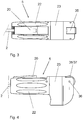
- Figur 1:
- eine räumliche Darstellung eines Instrumentes zum Schneiden von Körpergewebe mit eingeschwenkter Schneide und eingeklapptem Gewebeanschlag, d.h. Schneide und Gewebeanschlag befinden sich in einer Grundstellung;
- Figur 2:
- eine räumliche Darstellung des Instrumentes von
Figur 1 mit ausgeschwenkter Schneide und ausgeklapptem Gewebeanschlag; - Figur 3:
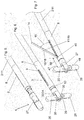
- eine Draufsicht auf das Bedienteil von
Figur 1 ; - Figur 4:
- eine Seitenansicht des Bedienteils von
Figur 3 ; - Figur 5:
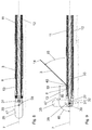
- eine räumliche Darstellung des distalen Endes von
Figur 1 mit eingeklapptem Gewebeanschlag (Grundstellung) und eingeschwenkter Schneide; - Figur 6:
- eine räumliche Darstellung des distalen Endes von
Figur 5 mit ausgeklapptem Gewebeanschlag (Wirkposition) und eingeschwenkter Schneide; - Figur 7:
- eine räumliche Darstellung des distalen Endes von
Figur 5 mit ausgeklapptem Gewebeanschlag (Wirkposition) und ausgeschwenkter Schneide; - Figur 8:
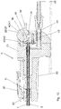
- eine Seitenansicht im Schnitt des distalen Endes von
Figur 5 ; - Figur 9:
- eine Seitenansicht im Schnitt des distalen Endes von
Figur 7 ; - Figur 10:
- eine Seitenansicht des Bedienteils von
Figur 1 im Schnitt und vergrößerter Darstellung. - Gleiche Bezugszeichen in den Figuren deuten auf gleiche oder analoge Bauteile hin. Die nachfolgende Beschreibung bezieht sich, sofern kein ausschließlicher Bezug auf eine spezielle Figur gegeben ist, auf sämtliche Figuren.
- Ein Instrument 1 zum Schneiden von Körpergewebe besteht im Wesentlichen aus einem Instrumentenschaft 2, einer Schneide 3, einem Gewebeanschlag 4 und einem Bedienteil 5.
- An einem dem Operateur abgewandten distalen Ende 6 des Instrumentenschaftes 2 ist eine um eine Längsachse 7 des Instrumentenschaftes 2 drehbare Außenhülse 8 angeordnet, die quer zu ihrer Längsachse eine seitliche Öffnung, d.h. einen rechtwinkligen Durchbruch, also eine Art Fenster, aufweist. Zum Operateur hin weist der Instrumentenschaft 2 an seinem proximalen Ende 10 das Bedienteil 5 auf. Der Instrumentenschaft 2 besteht aus einem Außenschaftrohr 11 und einem in dem Außenschaftrohr 11 beweglich (längsverschieblich und drehbar) geführten Innenschaftrohr 12.
- Das distale Ende 6 des Außenschaftrohres 11 ist mit dem proximalen Ende 6 der Außenhülse 8 über ein Gewinde für Reinigungszwecke lösbar verbunden. Zwischen der Außenhülse 8 und dem Innenschaftrohr 12 ist eine Innenhülse 13 angeordnet, die an ihrer proximalen Stirnseite in die Schneide 3 übergeht. Soweit die seitliche Öffnung 9 mit der Schneide 3 in Deckung gebracht wird, klappt die Schneide 3, die mit ihrem distalen Ende an der Innenhülse 13 angelenkt ist, mit ihrem in proximaler Richtung freien Ende 14 durch die seitliche Öffnung 9 hindurch und bildet gegenüber der Längsachse 7 einen maximalen Ausschwenkwinkel 15 von beispielsweise 45°.
- Die Schneide 3 weist an ihren beiden parallel zur Längsachse 7 verlaufenden Längsseiten 16, 17 eine Schneidkante 18 auf. Die Innenhülse 13 und die mit ihr verbundene Schneide 3 sind aus einer Formgedächtnislegierung ausgebildet, wobei der Anlenkstelle 19 der maximale Ausschwenkwinkel 15 eingeprägt ist. Formgedächtnislegierungen (shape memory alloy, SMA) die auch als Memory-Metalle bezeichnet werden, sind dem Fachmann bekannt. Diese weisen das Phänomen auf, dass sie sich an eine frühere Formgebung trotz nachfolgender starker Verformung scheinbar "erinnern" können. Als Werkstoffe kommen infrage:
- NiTi (Nickel-Titan; Nitinol)
- CuZn (Kupfer-Zink)
- CuZnAl (Kupfer-Zink-Aluminium)
- CuAlNi (Kupfer-Aluminium-Nickel)
- FeNiAl (Eisen-Nickel-Alumnium).
- Die Innenhülse 13 ist zusammen mit der Außenhülse 8 und dem Außenschaftrohr 11 um das Innenschaftrohr 12 drehbar. Das Außenschaftrohr 11 mit der Außenhülse 8 ist gegenüber dem Innenschaftrohr 12 und der Innenhülse 13 längsverschieblich ausgebildet. Durch die Längsverschiebung zwischen Außenhülse 8 und Innenhülse 13 folgt das ein- bzw. Ausklappen der Schneide 3 aus der seitlichen Öffnung 9 der Außenhülse 8.
- Über ein am Bedienteil 5 angeordnetes längsverschiebliches erstes Bedienelement 20, das mit dem proximalen Ende 21 des Außenschaftrohres 11 verbunden ist, lässt sich die Außenhülse 8 gegenüber der Innenhülse 13 mit der Schneide 3 in Längsrichtung verschieben, so dass die Schneide 3 an ihrer Anlenkstelle 19 abgedeckt und damit eingeklappt/eingeschwenkt wird oder freigegeben und damit ausgeklappt/ausgeschwenkt wird.
- Das Bedienteil 5 weist ein zweites Bedienelement 22 auf, das um die Längsachse 7 drehbar an einem mit dem Innenschaftrohr 12 fest verbundenen Hauptkörper 23 des Bedienteils 5 gelagert ist. In dem zweiten Bedienelement 22 des Bedienteiles 5 ist das erste Bedienelement 20 längsverschieblich und über eine Rastvorrichtung 24 in unterschiedlichen Raststellungen verrastbar. Durch Drehen des zweiten Bedienelementes 22 lässt sich das Außenschaftrohr 11 mit Außenhülse 8 und dem ersten Bedienelement 20 um das Innenschaftrohr 12 drehen. Wird das erste Bedienelement 20 in proximaler Richtung zurückgezogen, wird die Schneide 3 eingeklappt. Wird das erste Bedienelement 20 in distaler Richtung verschoben, wird die Schneide, je nach Deckungsgrad der seitlichen Öffnung mit der Schneide ausgeklappt/ausgeschwenkt. Unterschiedliche Raststellungen des ersten Bedienelementes 20 führen somit zu unterschiedlichen Ausschwenkwinkeln 15 der Schneide 3.
- In Verlängerung des Instrumentenschaftes 2 ist an dessen distalem Ende 6 der Gewebeanschlag 4 angeordnet. Der Gewebeanschlag 4 besteht aus zwei entgegengesetzt zueinander verschwenkbaren Backen 25, 26, die in einer u-förmigen Aufnahme 27 angeordnet sind. Die Backen 25, 26 weisen jeweils eine Führungsnut 28, 29 auf. Die beiden Führungsnuten 28, 29 sind spiegelsymmetrisch zueinander ausgebildet. Die Backen 25, 26 mit ihren Führungsnuten 28, 29 sind damit entgegengesetzt zueinander um eine quer zur Längsachse 7 in der Aufnahme 27 angeordnete erste Querachse 30 verschwenkbar. Dabei sind die Backen 25, 26 an ihren proximalen Enden über eine zweite Querachse 31 mit einem distalen Ende 32 einer in dem Innenschaftrohr 12 längsverschieblich geführten Hubstange 33 verbunden. Die Hubstange steht an ihrem proximalen Ende 34 im Bedienteil 5 mit einem dritten Bedienelement 35 in einer Wirkverbindung.
- Das dritte Bedienelement 35 ist als ein um eine dritte Querachse 36, die parallel zur ersten Querachse 30 und zweiten Querachse 31 angeordnet ist, drehbares Rad 37 mit einem radial angeordneten Bedienhebel 38 ausgebildet. Das Rad 37 ist über eine seitlich und quer verlaufende Ausformung 39 mit dem proximalen Ende 34 der Hubstange 33 verbunden. Über eine Teildrehung des Rades 37 lässt sich über die Hubstange 33 der Gewebeanschlag 4 zwischen einer Grundstellung mit eingeklappten Backen 25, 26 und einer maximal ausgeklappten Stellung der Backen 25, 26 verstellen. End- und Zwischenstellungen sind dabei über eine zwischen dem dritten Bedienelement 35 und dem Bedienteil 5 angeordnete zweite Rastvorrichtung 40 fixierbar. Hierzu weist das Rad 37 an seinem Umfang Rastnuten 41 auf, in die ein federndes Rastteil 42 eingreifen kann. Damit ist der Gewebeanschlag 4 in unterschiedlichen Raststellungen bzw. Spreizstellungen verrastbar.
- Die Backen 25, 26 bilden mit ihren in Aufklapprichtung außenliegenden Kanten die Anschlagflächen 47, 48, die in ihrer Wirkposition gegenüber der Längsachse 7 einen Ausklappwinkel 49 von beispielsweise 90° aufweisen und zur Anlenkstelle 19 einen fixen Abstand 50 von > 1,5 mm aufweisen. In den Ausführungsbeispielen beträgt der fixe Abstand 50 etwa 12 mm.
- In den Ausführungsbeispielen ist die Schneide 3 als eine Elektrode ausgebildet, die mit einem Steckkontakt 43 am Bedienteil 5 elektrisch leitend verbunden ist. Der Steckkontakt 43 ist mit einer Steckerbuchse 44 eines Elektrodenkabels 45 verbindbar, das zu einem nicht dargestellten Elektrochirurgiegerät, einem Hochfrequenzgenerator, führt.
- Natürlich stellen die in der speziellen Beschreibung diskutierten und in den Figuren gezeigten Ausführungsformen nur illustrative Ausführungsbeispiele der vorliegenden Erfindung dar. Dem Fachmann ist im Lichte der hiesigen Offenbarung ein breites Spektrum von Variationsmöglichkeiten an die Hand gegeben.
- Insbesondere kann der Gewebeanschlag 4, der gegenüber der Schneide 3 elektrisch isoliert ausgebildet ist, als eine zweite Elektrode verwendet werden, so dass der Gewebeanschlag 4 und die Schneide 3 ein bipolares Elektrodenpaar bildet, das mit dem nicht dargestellten Hochfrequenzgenerator bzw. elektrochirurgischen Gerät verbunden werden kann.
-
- 1
- Instrument
- 2
- Instrumentenschaft
- 3
- Schneide
- 4
- Gewebeanschlag
- 5
- Bedienteil
- 6
- distales Ende von 2
- 7
- Längsachse von 2
- 8
- Außenhülse
- 9
- seitliche Öffnung von 8
- 10
- proximales Ende von 2
- 11
- Außenschaftrohr von 2
- 12
- Innenschaftrohr von 2
- 13
- Innenhülse
- 14
- freies Ende von 3
- 15
- Ausschwenkwinkel von 3
- 16
- erste Längsseite von 3
- 17
- zweite Längsseite von 3
- 18
- Schneidkante
- 19
- Anlenkstelle von 3
- 20
- erstes Bedienelement
- 21
- proximales Ende von 11
- 22
- zweites Bedienelement
- 23
- Hauptkörper von 5
- 24
- Rastvorrichtung von 20, 22
- 25
- erste Backe von 4
- 26
- zweite Backe von 4
- 27
- u-förmige Ausnahme
- 28
- erste Führungsnut
- 29
- zweite Führungsnut
- 30
- erste Querachse von 27
- 31
- zweite Querachse
- 32
- distales Ende von 33
- 33
- Hubstange
- 34
- proximales Ende von 33
- 35
- drittes Bedienelement
- 36
- dritte Querachse
- 37
- Rad von 35
- 38
- Bedienhebel von 35
- 39
- Ausformung
- 40
- zweite Rastvorrichtung von 35
- 41
- Rastnuten von 40
- 42
- Rastteil von 40
- 43
- Steckkontakt
- 44
- Steckerbuchse
- 45
- Elektrodenkabel
- 46
- distal angelenktes Ende von 3
- 47
- erste Anschlagfläche von 4
- 48
- zweite Anschlagfläche
- 49
- Ausklappwinkel von 47, 48
- 50
- Abstand
Claims (14)
- Instrument (1) zum Schneiden von Körpergewebe umfassend- einen Instrumentenschaft (2),- eine dem distalen Ende (6) des Instrumentenschaftes 82) benachbart angeordnete, gegenüber einer Längsachse (7) des Schaftes (2) ausklappbare und um die Längsachse (7) drehbare Schneide (3), und- ein am proximalen Ende (10) des Instrumentenschaftes (2) angeordnetes Bedienteil (5),wobei das distales Ende (6)des Instrumentenschaftes durch eine Trokarhülse in eine Körperhöhle mit zu schneidendem Gewebe einführbar ist,
wobei die Schneide (3) mit einem zum Bedienteil (5) hin gerichteten proximalen Ende (14) von der Längsachse weggerichtet um ihr dem proximalen Ende (14) abgewandtes und an einer Anlenkstelle (19) distal angelenktes Ende (46) seitlich ausschwenkbar ist,
und wobei am distalen Ende (6) des Instrumentenschaftes (2) ein Gewebeanschlag (4) angeordnet ist, und der Gewebeanschlag in eine Wirkposition bringbar ist, in der eine in proximaler Richtung zur Schneide (3) gewandte Anschlagfläche (47, 48) einen vorgegebenen fixen Abstand (50) zur Anlenkstelle (19) aufweist,
dadurch gekennzeichnet,
dass am distalen Ende (6) des Instrumentenschaftes (2) eine um die Längsachse (7) drehbare Außenhülse (8) angeordnet ist, die quer zu ihrer Längsrichtung eine seitliche Öffnung (9) aufweist, aus der die Schneide (3) ausschwenkbar ist. - Instrument nach Anspruch 1,
dadurch gekennzeichnet,
dass der fixe Abstand (50) größer als 1,5 mm ist. - Instrument nach Anspruch 1 oder 2,
dadurch gekennzeichnet,
dass der Gewebeanschlag (4) um eine am distalen Ende (6) des Instrumentenschaftes (2) angeordnete erste Querachse (30)in seine Wirkposition ausklappbar ist. - Instrument nach einem der Ansprüche 1 bis 3,
dadurch gekennzeichnet,
dass die Schneide (3) an mindestens einer ihrer beiden parallel zur Längsachse (7) verlaufenden Längsseiten (16, 17) eine Schneidkante (18) aufweist. - Instrument nach einem der Ansprüche 1 bis 4,
dadurch gekennzeichnet,
dass der Instrumentenschaft (2) ein Außenschaftrohr (11) aufweist, dessen distales Ende (6) mit der Außenhülse (8) verbunden ist,
dass in dem Außenschaftrohr (11) ein Innenschaftrohr (12) angeordnet ist,
dass zwischen Außenhülse (8) und Innenschaftrohr (12) eine an ihrer proximalen Stirnseite die Schneide (3) aufweisende Innenhülse (13) angeordnet ist,
dass die Innenhülse (13) zusammen mit der Außenhülse (8) und dem Außenschaftrohr (11) um das Innenschaftrohr (12) drehbar ist, und
dass das Außenschaftrohr (11) mit der Außenhülse (8) gegenüber dem Innenschaftrohr (12) und der Innenhülse (13) längsverschieblich ausgebildet sind. - Instrument nach Anspruch 5,
dadurch gekennzeichnet,
dass die Innenhülse (13) und die Schneide (3) mindestens im Bereich ihrer Anlenkstelle (19) aus einer Formgedächtnislegierung ausgebildet sind. - Instrument nach einem der Ansprüche 1 bis 6,
dadurch gekennzeichnet,
dass über ein am Bedienteil (5) angeordnetes längsverschiebliches erstes Bedienelement (20) die Außenhülse (8) über das Außenschaftrohr (11) zum Betätigen der Schneide (3) verschiebbar ist. - Instrument nach Anspruch 7,
dadurch gekennzeichnet,
dass das erste Bedienelement (20) in unterschiedlichen Raststellungen verrastbar ist. - Instrument nach Anspruch 7 oder 8,
dadurch gekennzeichnet,
dass über ein am Bedienteil (5) angeordnetes drehbares zweites Bedienelement (22) das Außenschaftrohr (11) mit der aus der Außenhülse (8) ausgeschwenkten Schneide (3) um die Längsachse (7) drehbar ist. - Instrument nach einem der Ansprüche 1 bis 9,
dadurch gekennzeichnet,
dass die Schneide (3) als eine Elektrode ausgebildet ist. - Instrument nach einem der Ansprüche 5 bis 10,
dadurch gekennzeichnet,
dass der Gewebeanschlag (4) am distalen Ende (6) des Instrumentenschaftes (2) zwei in einer u-förmigen Aufnahme (27) angeordnete Backen (25, 26) mit spiegelsymmetrisch ausgebildeten Führungsnuten (28, 29) aufweist,
dass die Backen (25, 26) mit ihren Führungsnuten (28, 29) entgegengesetzt zueinander um eine quer zur Längsachse (7) in der Aufnahme (27) angeordnete erste Querachse (30) verschwenkbar sind, und
dass die Backen (25, 26) an ihren proximalen Enden über eine zweite Querachse (31) mit einem distalen Ende (32) einer in dem Innenschaftrohr (12) längsverschieblich geführten Hubstange (33) verbunden sind. - Instrument nach Anspruch 11,
dadurch gekennzeichnet,
dass die Hubstange (33) an ihrem dem distalen Ende (32) abgewandten proximalen Ende (34) im Bedienteil (5) mit einem dritten Bedienelement (35) in Wirkverbindung steht. - Instrument nach Anspruch 12,
dadurch gekennzeichnet,
dass der Gewebeanschlag (4) über das dritte Bedienelement (35) in unterschiedlichen Raststellungen verrastbar ist. - Instrument nach einem der Ansprüche 1 bis 13,
dadurch gekennzeichnet,
dass der Gewebeanschlag (4) als eine Elektrode ausgebildet ist.
Priority Applications (1)
| Application Number | Priority Date | Filing Date | Title |
|---|---|---|---|
| PL13744454T PL2872063T3 (pl) | 2012-07-12 | 2013-07-10 | Instrument do cięcia tkanki |
Applications Claiming Priority (2)
| Application Number | Priority Date | Filing Date | Title |
|---|---|---|---|
| DE102012013738.9A DE102012013738B4 (de) | 2012-07-12 | 2012-07-12 | Instrument zum Schneiden von Körpergewebe |
| PCT/EP2013/064593 WO2014009420A1 (de) | 2012-07-12 | 2013-07-10 | Instrument zum schneiden von körpergewebe |
Publications (2)
| Publication Number | Publication Date |
|---|---|
| EP2872063A1 EP2872063A1 (de) | 2015-05-20 |
| EP2872063B1 true EP2872063B1 (de) | 2016-08-17 |
Family
ID=48914226
Family Applications (1)
| Application Number | Title | Priority Date | Filing Date |
|---|---|---|---|
| EP13744454.3A Active EP2872063B1 (de) | 2012-07-12 | 2013-07-10 | Instrument zum schneiden von körpergewebe |
Country Status (7)
| Country | Link |
|---|---|
| US (1) | US9855093B2 (de) |
| EP (1) | EP2872063B1 (de) |
| DE (1) | DE102012013738B4 (de) |
| DK (1) | DK2872063T3 (de) |
| ES (1) | ES2603753T3 (de) |
| PL (1) | PL2872063T3 (de) |
| WO (1) | WO2014009420A1 (de) |
Families Citing this family (1)
| Publication number | Priority date | Publication date | Assignee | Title |
|---|---|---|---|---|
| US10076315B2 (en) | 2014-09-18 | 2018-09-18 | Transmed7, Llc | Soft tissue biopsy or excisional devices and methods |
Family Cites Families (14)
| Publication number | Priority date | Publication date | Assignee | Title |
|---|---|---|---|---|
| DE2949278C2 (de) * | 1979-12-07 | 1982-05-27 | Rainer Dipl.-Ing. 8261 Neuötting Kortländer | Vorrichtung zur Messerkonisation des Gebärmutterhalses |
| DE3831967C1 (de) * | 1988-09-21 | 1990-02-08 | Michael Dr. 7400 Tuebingen De Menton | |
| US5047042A (en) * | 1990-02-09 | 1991-09-10 | Ravinder Jerath | Cervical conization method and instrument |
| US5554159A (en) * | 1994-02-04 | 1996-09-10 | Fischer; Nathan R. | Instrument for electro-surgical excisor for the transformation zone of the uterine cervix and method of using same |
| US5676663A (en) * | 1995-11-21 | 1997-10-14 | Kim; David S. | Cone biopsy instrument |
| US6540693B2 (en) * | 1998-03-03 | 2003-04-01 | Senorx, Inc. | Methods and apparatus for securing medical instruments to desired locations in a patients body |
| US5951550A (en) * | 1998-03-11 | 1999-09-14 | Utah Medical Products, Inc. | Endocervical conization electrode apparatus |
| GB2347083B (en) * | 1999-02-24 | 2001-06-27 | Samuel George | Surgical biopsy instrument |
| US6309388B1 (en) * | 1999-12-23 | 2001-10-30 | Mayo Foundation For Medical Education And Research | Symmetric conization electrocautery device |
| TW510788B (en) * | 2000-08-24 | 2002-11-21 | Surgical Connections Inc | Surgical stabilizer devices and methods |
| US20030109872A1 (en) * | 2001-12-11 | 2003-06-12 | Muzzammel Mohiuddin M. | Variable angle cervical excision electrode |
| US6641581B2 (en) * | 2001-12-11 | 2003-11-04 | Mohiuddin M. Muzzammel | Variable angle cervical excision electrode |
| US6793635B2 (en) * | 2002-06-28 | 2004-09-21 | Ethicon, Inc. | Devices having deployable ultrasound transducers and method of use of same |
| US8608738B2 (en) * | 2010-12-06 | 2013-12-17 | Soulor Surgical, Inc. | Apparatus for treating a portion of a reproductive system and related methods of use |
-
2012
- 2012-07-12 DE DE102012013738.9A patent/DE102012013738B4/de not_active Expired - Fee Related
-
2013
- 2013-07-10 DK DK13744454.3T patent/DK2872063T3/en active
- 2013-07-10 ES ES13744454.3T patent/ES2603753T3/es active Active
- 2013-07-10 PL PL13744454T patent/PL2872063T3/pl unknown
- 2013-07-10 EP EP13744454.3A patent/EP2872063B1/de active Active
- 2013-07-10 WO PCT/EP2013/064593 patent/WO2014009420A1/de active Application Filing
- 2013-07-10 US US14/410,250 patent/US9855093B2/en active Active
Also Published As
| Publication number | Publication date |
|---|---|
| WO2014009420A1 (de) | 2014-01-16 |
| US20150366606A1 (en) | 2015-12-24 |
| DE102012013738B4 (de) | 2016-03-03 |
| PL2872063T3 (pl) | 2017-04-28 |
| EP2872063A1 (de) | 2015-05-20 |
| DE102012013738A1 (de) | 2014-01-16 |
| ES2603753T3 (es) | 2017-03-01 |
| DK2872063T3 (en) | 2016-11-28 |
| US9855093B2 (en) | 2018-01-02 |
Similar Documents
| Publication | Publication Date | Title |
|---|---|---|
| EP1056401B1 (de) | Vorrichtung zur behandlung von körpergewebe mittels ultraschall | |
| DE19603981C2 (de) | Medizinisches Instrument zur Uterusmanipulation | |
| DE69636839T2 (de) | Endochirurgisches instrument mit einem radialbeweglichem griff | |
| DE112011101324B4 (de) | Chirurgisches Instrument | |
| DE19935478C1 (de) | Endoskopisch einsetzbares chirurgisches Instrument zur Koagulation mittels Hochfrequenz und zur Durchführung koagulierter Gewebebereiche | |
| EP2007293B1 (de) | Endoskopisches multifunktions-chirurgiegerät | |
| DE60030360T2 (de) | Laparoskopische gebogene Schere mit zwei Krümmungsbögen | |
| EP1051119B1 (de) | Instrument zum applizieren von licht, insbesondere laserlicht, im menschlichen oder tierischen körper | |
| EP2245990B1 (de) | Medizinisches Instrument zum Dilatieren von knöchernen Strukturen | |
| EP3629943B1 (de) | Vorrichtung zur retraktion von weichgewebe in einem patienten während einer arthroskopischen operation | |
| EP2769682A1 (de) | Endoskopisches Instrument sowie Schaft für ein endoskopisches Instrument | |
| DE4421822C1 (de) | Endoskopisches, bipolares HF-Koagulationsgerät mit integrierter Schneideeinrichtung | |
| EP1752107A1 (de) | Medizinisches Instrument | |
| EP2872063B1 (de) | Instrument zum schneiden von körpergewebe | |
| EP0918489B1 (de) | Trokarhülse für die endoskopie | |
| EP2725988B1 (de) | Trokarsystem | |
| WO1998037817A1 (de) | Medizinischer dissektionsspatel mit spreizbaren spatelmaulteilen | |
| DE112020005581T5 (de) | Kolpotomie-schalen-anordnung | |
| DE202017004226U1 (de) | Chirurgisches Instrument | |
| DE102017114449A1 (de) | Arbeitselement eines Resektoskops sowie Resektoskop | |
| EP2653119B1 (de) | Medizinisches Instrument und Verfahren zum Zusammensetzen eines medizinischen Instruments | |
| EP2653118B1 (de) | Mikroinvasives medizinisches Instrument | |
| DE202022102754U1 (de) | Elektrochirurgisches Skalpell | |
| DE10145107B4 (de) | Füllstab für Endoskope | |
| DE202017103690U1 (de) | Medizinisches Instrument |
Legal Events
| Date | Code | Title | Description |
|---|---|---|---|
| PUAI | Public reference made under article 153(3) epc to a published international application that has entered the european phase |
Free format text: ORIGINAL CODE: 0009012 |
|
| 17P | Request for examination filed |
Effective date: 20141202 |
|
| AK | Designated contracting states |
Kind code of ref document: A1 Designated state(s): AL AT BE BG CH CY CZ DE DK EE ES FI FR GB GR HR HU IE IS IT LI LT LU LV MC MK MT NL NO PL PT RO RS SE SI SK SM TR |
|
| AX | Request for extension of the european patent |
Extension state: BA ME |
|
| RIN1 | Information on inventor provided before grant (corrected) |
Inventor name: NOE, KARL-GUENTER Inventor name: DOPPELSTEIN, ALEXANDER Inventor name: GRAF, THOMAS Inventor name: SPUENTRUP, CAROLIN |
|
| DAX | Request for extension of the european patent (deleted) | ||
| GRAP | Despatch of communication of intention to grant a patent |
Free format text: ORIGINAL CODE: EPIDOSNIGR1 |
|
| INTG | Intention to grant announced |
Effective date: 20160115 |
|
| INTG | Intention to grant announced |
Effective date: 20160218 |
|
| GRAS | Grant fee paid |
Free format text: ORIGINAL CODE: EPIDOSNIGR3 |
|
| GRAA | (expected) grant |
Free format text: ORIGINAL CODE: 0009210 |
|
| AK | Designated contracting states |
Kind code of ref document: B1 Designated state(s): AL AT BE BG CH CY CZ DE DK EE ES FI FR GB GR HR HU IE IS IT LI LT LU LV MC MK MT NL NO PL PT RO RS SE SI SK SM TR |
|
| REG | Reference to a national code |
Ref country code: GB Ref legal event code: FG4D Free format text: NOT ENGLISH |
|
| REG | Reference to a national code |
Ref country code: CH Ref legal event code: EP |
|
| REG | Reference to a national code |
Ref country code: IE Ref legal event code: FG4D Free format text: LANGUAGE OF EP DOCUMENT: GERMAN |
|
| REG | Reference to a national code |
Ref country code: AT Ref legal event code: REF Ref document number: 820304 Country of ref document: AT Kind code of ref document: T Effective date: 20160915 |
|
| REG | Reference to a national code |
Ref country code: DE Ref legal event code: R096 Ref document number: 502013004087 Country of ref document: DE |
|
| REG | Reference to a national code |
Ref country code: CH Ref legal event code: NV Representative=s name: ROSENICH PAUL; KUENSCH JOACHIM PATENTBUERO PAU, LI |
|
| REG | Reference to a national code |
Ref country code: DK Ref legal event code: T3 Effective date: 20161125 |
|
| REG | Reference to a national code |
Ref country code: NL Ref legal event code: MP Effective date: 20160817 |
|
| REG | Reference to a national code |
Ref country code: LT Ref legal event code: MG4D |
|
| PG25 | Lapsed in a contracting state [announced via postgrant information from national office to epo] |
Ref country code: RS Free format text: LAPSE BECAUSE OF FAILURE TO SUBMIT A TRANSLATION OF THE DESCRIPTION OR TO PAY THE FEE WITHIN THE PRESCRIBED TIME-LIMIT Effective date: 20160817 Ref country code: HR Free format text: LAPSE BECAUSE OF FAILURE TO SUBMIT A TRANSLATION OF THE DESCRIPTION OR TO PAY THE FEE WITHIN THE PRESCRIBED TIME-LIMIT Effective date: 20160817 Ref country code: NO Free format text: LAPSE BECAUSE OF FAILURE TO SUBMIT A TRANSLATION OF THE DESCRIPTION OR TO PAY THE FEE WITHIN THE PRESCRIBED TIME-LIMIT Effective date: 20161117 Ref country code: LT Free format text: LAPSE BECAUSE OF FAILURE TO SUBMIT A TRANSLATION OF THE DESCRIPTION OR TO PAY THE FEE WITHIN THE PRESCRIBED TIME-LIMIT Effective date: 20160817 Ref country code: FI Free format text: LAPSE BECAUSE OF FAILURE TO SUBMIT A TRANSLATION OF THE DESCRIPTION OR TO PAY THE FEE WITHIN THE PRESCRIBED TIME-LIMIT Effective date: 20160817 Ref country code: NL Free format text: LAPSE BECAUSE OF FAILURE TO SUBMIT A TRANSLATION OF THE DESCRIPTION OR TO PAY THE FEE WITHIN THE PRESCRIBED TIME-LIMIT Effective date: 20160817 |
|
| PG25 | Lapsed in a contracting state [announced via postgrant information from national office to epo] |
Ref country code: LV Free format text: LAPSE BECAUSE OF FAILURE TO SUBMIT A TRANSLATION OF THE DESCRIPTION OR TO PAY THE FEE WITHIN THE PRESCRIBED TIME-LIMIT Effective date: 20160817 Ref country code: SE Free format text: LAPSE BECAUSE OF FAILURE TO SUBMIT A TRANSLATION OF THE DESCRIPTION OR TO PAY THE FEE WITHIN THE PRESCRIBED TIME-LIMIT Effective date: 20160817 Ref country code: GR Free format text: LAPSE BECAUSE OF FAILURE TO SUBMIT A TRANSLATION OF THE DESCRIPTION OR TO PAY THE FEE WITHIN THE PRESCRIBED TIME-LIMIT Effective date: 20161118 Ref country code: PT Free format text: LAPSE BECAUSE OF FAILURE TO SUBMIT A TRANSLATION OF THE DESCRIPTION OR TO PAY THE FEE WITHIN THE PRESCRIBED TIME-LIMIT Effective date: 20161219 |
|
| REG | Reference to a national code |
Ref country code: ES Ref legal event code: FG2A Ref document number: 2603753 Country of ref document: ES Kind code of ref document: T3 Effective date: 20170301 |
|
| PG25 | Lapsed in a contracting state [announced via postgrant information from national office to epo] |
Ref country code: RO Free format text: LAPSE BECAUSE OF FAILURE TO SUBMIT A TRANSLATION OF THE DESCRIPTION OR TO PAY THE FEE WITHIN THE PRESCRIBED TIME-LIMIT Effective date: 20160817 Ref country code: EE Free format text: LAPSE BECAUSE OF FAILURE TO SUBMIT A TRANSLATION OF THE DESCRIPTION OR TO PAY THE FEE WITHIN THE PRESCRIBED TIME-LIMIT Effective date: 20160817 |
|
| REG | Reference to a national code |
Ref country code: DE Ref legal event code: R097 Ref document number: 502013004087 Country of ref document: DE |
|
| PG25 | Lapsed in a contracting state [announced via postgrant information from national office to epo] |
Ref country code: SM Free format text: LAPSE BECAUSE OF FAILURE TO SUBMIT A TRANSLATION OF THE DESCRIPTION OR TO PAY THE FEE WITHIN THE PRESCRIBED TIME-LIMIT Effective date: 20160817 Ref country code: SK Free format text: LAPSE BECAUSE OF FAILURE TO SUBMIT A TRANSLATION OF THE DESCRIPTION OR TO PAY THE FEE WITHIN THE PRESCRIBED TIME-LIMIT Effective date: 20160817 Ref country code: BG Free format text: LAPSE BECAUSE OF FAILURE TO SUBMIT A TRANSLATION OF THE DESCRIPTION OR TO PAY THE FEE WITHIN THE PRESCRIBED TIME-LIMIT Effective date: 20161117 Ref country code: CZ Free format text: LAPSE BECAUSE OF FAILURE TO SUBMIT A TRANSLATION OF THE DESCRIPTION OR TO PAY THE FEE WITHIN THE PRESCRIBED TIME-LIMIT Effective date: 20160817 |
|
| PLBE | No opposition filed within time limit |
Free format text: ORIGINAL CODE: 0009261 |
|
| STAA | Information on the status of an ep patent application or granted ep patent |
Free format text: STATUS: NO OPPOSITION FILED WITHIN TIME LIMIT |
|
| REG | Reference to a national code |
Ref country code: FR Ref legal event code: PLFP Year of fee payment: 5 |
|
| 26N | No opposition filed |
Effective date: 20170518 |
|
| PG25 | Lapsed in a contracting state [announced via postgrant information from national office to epo] |
Ref country code: SI Free format text: LAPSE BECAUSE OF FAILURE TO SUBMIT A TRANSLATION OF THE DESCRIPTION OR TO PAY THE FEE WITHIN THE PRESCRIBED TIME-LIMIT Effective date: 20160817 |
|
| REG | Reference to a national code |
Ref country code: IE Ref legal event code: MM4A |
|
| PG25 | Lapsed in a contracting state [announced via postgrant information from national office to epo] |
Ref country code: IE Free format text: LAPSE BECAUSE OF NON-PAYMENT OF DUE FEES Effective date: 20170710 |
|
| REG | Reference to a national code |
Ref country code: BE Ref legal event code: MM Effective date: 20170731 |
|
| PG25 | Lapsed in a contracting state [announced via postgrant information from national office to epo] |
Ref country code: LU Free format text: LAPSE BECAUSE OF NON-PAYMENT OF DUE FEES Effective date: 20170710 |
|
| REG | Reference to a national code |
Ref country code: FR Ref legal event code: PLFP Year of fee payment: 6 |
|
| PG25 | Lapsed in a contracting state [announced via postgrant information from national office to epo] |
Ref country code: BE Free format text: LAPSE BECAUSE OF NON-PAYMENT OF DUE FEES Effective date: 20170731 |
|
| PG25 | Lapsed in a contracting state [announced via postgrant information from national office to epo] |
Ref country code: MT Free format text: LAPSE BECAUSE OF FAILURE TO SUBMIT A TRANSLATION OF THE DESCRIPTION OR TO PAY THE FEE WITHIN THE PRESCRIBED TIME-LIMIT Effective date: 20160817 |
|
| PG25 | Lapsed in a contracting state [announced via postgrant information from national office to epo] |
Ref country code: AL Free format text: LAPSE BECAUSE OF FAILURE TO SUBMIT A TRANSLATION OF THE DESCRIPTION OR TO PAY THE FEE WITHIN THE PRESCRIBED TIME-LIMIT Effective date: 20160817 |
|
| PG25 | Lapsed in a contracting state [announced via postgrant information from national office to epo] |
Ref country code: HU Free format text: LAPSE BECAUSE OF FAILURE TO SUBMIT A TRANSLATION OF THE DESCRIPTION OR TO PAY THE FEE WITHIN THE PRESCRIBED TIME-LIMIT; INVALID AB INITIO Effective date: 20130710 Ref country code: MC Free format text: LAPSE BECAUSE OF FAILURE TO SUBMIT A TRANSLATION OF THE DESCRIPTION OR TO PAY THE FEE WITHIN THE PRESCRIBED TIME-LIMIT Effective date: 20160817 |
|
| PG25 | Lapsed in a contracting state [announced via postgrant information from national office to epo] |
Ref country code: CY Free format text: LAPSE BECAUSE OF FAILURE TO SUBMIT A TRANSLATION OF THE DESCRIPTION OR TO PAY THE FEE WITHIN THE PRESCRIBED TIME-LIMIT Effective date: 20160817 |
|
| PG25 | Lapsed in a contracting state [announced via postgrant information from national office to epo] |
Ref country code: MK Free format text: LAPSE BECAUSE OF FAILURE TO SUBMIT A TRANSLATION OF THE DESCRIPTION OR TO PAY THE FEE WITHIN THE PRESCRIBED TIME-LIMIT Effective date: 20160817 |
|
| PG25 | Lapsed in a contracting state [announced via postgrant information from national office to epo] |
Ref country code: IS Free format text: LAPSE BECAUSE OF FAILURE TO SUBMIT A TRANSLATION OF THE DESCRIPTION OR TO PAY THE FEE WITHIN THE PRESCRIBED TIME-LIMIT Effective date: 20161217 |
|
| REG | Reference to a national code |
Ref country code: CH Ref legal event code: PCAR Free format text: NEW ADDRESS: ROTENBODENSTRASSE 12, 9497 TRIESENBERG (LI) |
|
| P01 | Opt-out of the competence of the unified patent court (upc) registered |
Effective date: 20230517 |
|
| PGFP | Annual fee paid to national office [announced via postgrant information from national office to epo] |
Ref country code: PL Payment date: 20230512 Year of fee payment: 11 |
|
| PGFP | Annual fee paid to national office [announced via postgrant information from national office to epo] |
Ref country code: TR Payment date: 20230706 Year of fee payment: 11 Ref country code: IT Payment date: 20230731 Year of fee payment: 11 Ref country code: GB Payment date: 20230724 Year of fee payment: 11 Ref country code: ES Payment date: 20230821 Year of fee payment: 11 Ref country code: CH Payment date: 20230801 Year of fee payment: 11 Ref country code: AT Payment date: 20230718 Year of fee payment: 11 |
|
| PGFP | Annual fee paid to national office [announced via postgrant information from national office to epo] |
Ref country code: FR Payment date: 20230724 Year of fee payment: 11 Ref country code: DK Payment date: 20230724 Year of fee payment: 11 Ref country code: DE Payment date: 20230512 Year of fee payment: 11 |